
Module i Lecture 2
21
NODAL AND MESH ANALYSIS Galgotias University
-
Upload
agnivesh-sharma -
Category
Documents
-
view
239 -
download
4
Transcript of Module i Lecture 2

NODAL AND MESH ANALYSIS
Galgotias University
Basic CircuitsNodal Analysis: The Concept.
• Every circuit has n nodes with one of the nodes beingdesignated as a reference node.
• We designate the remaining n – 1 nodes as voltage nodesand give each node a unique name, vi.
• At each node we write Kirchhoff’s current law in termsof the node voltages.
1Galgotias University
Basic CircuitsNodal Analysis: The Concept.
• We form n-1 linear equations at the n-1 nodesin terms of the node voltages.
• We solve the n-1 equations for the n-1 node voltages.
• From the node voltages we can calculate any branchcurrent or any voltage across any element.
2 Galgotias University
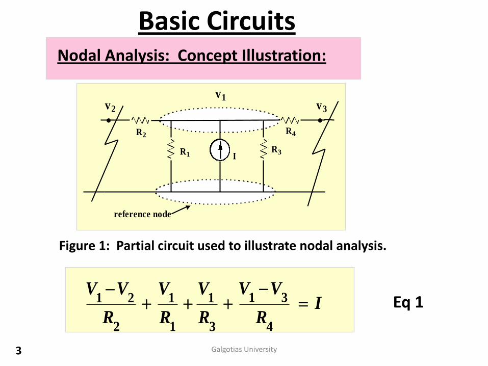
Basic CircuitsNodal Analysis: Concept Illustration:
reference node
v1v2 v3
R2
R1R3
R4
I
Figure 1: Partial circuit used to illustrate nodal analysis.
IR
VV
R
V
R
V
R
VV
4
31
3
1
1
1
2
21 Eq 1
3 Galgotias University
Basic Circuits
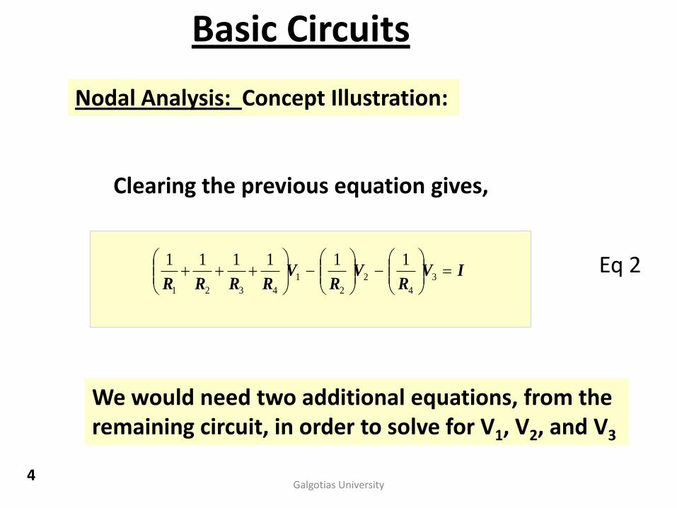
Nodal Analysis: Concept Illustration:
Clearing the previous equation gives,
IVR
VR
VRRRR
3
4
2
2
1
4321
111111 Eq 2
We would need two additional equations, from theremaining circuit, in order to solve for V1, V2, and V3
4Galgotias University
Basic Circuits
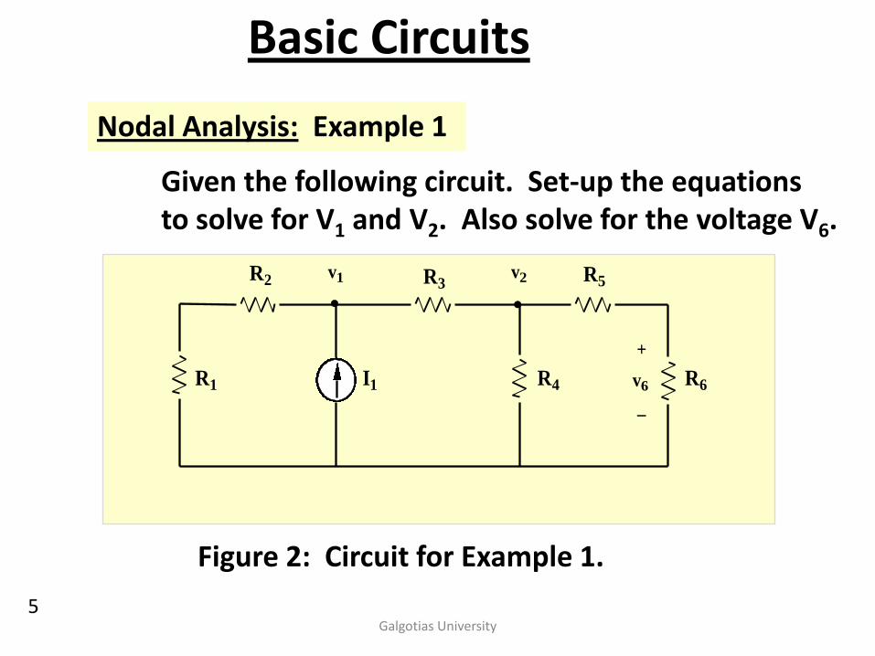
Nodal Analysis: Example 1
Given the following circuit. Set-up the equations to solve for V1 and V2. Also solve for the voltage V6.
R2 R3
R1 R4
R5
R6I1
v1 v2
+
_
v6
Figure 2: Circuit for Example 1.
5Galgotias University
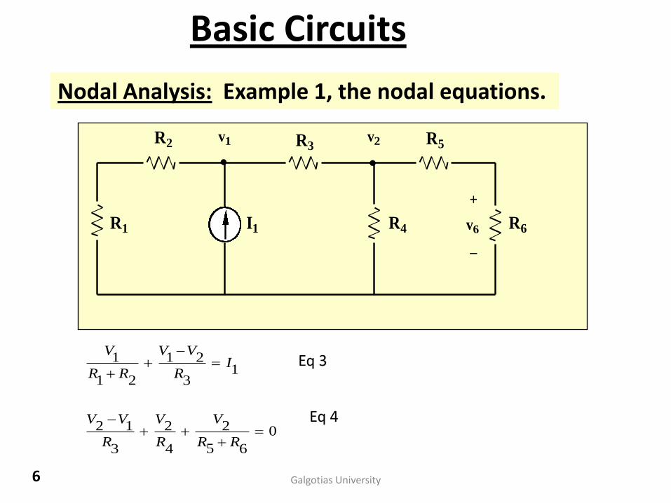
Basic Circuits
Nodal Analysis: Example 1, the nodal equations.
R2 R3
R1 R4
R5
R6I1
v1 v2
+
_
v6
0
65
2
4
2
3
12
13
21
21
1
RR
V
R
V
R
VV
IR
VV
RR
VEq 3
Eq 4
6 Galgotias University
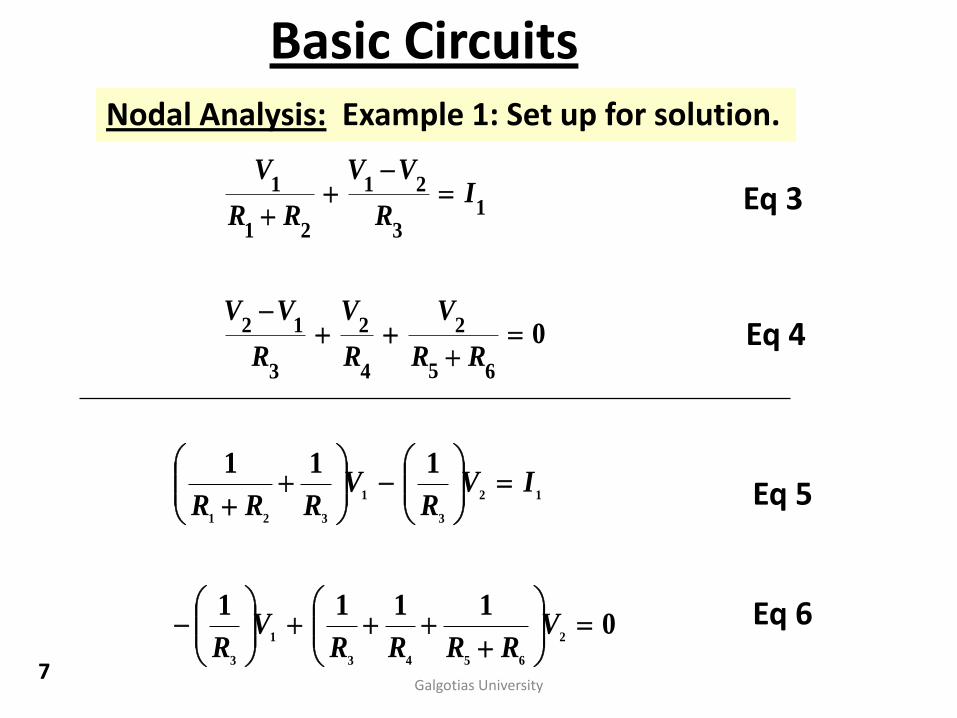
Basic CircuitsNodal Analysis: Example 1: Set up for solution.
0
65
2
4
2
3
12
13
21
21
1
RR
V
R
V
R
VV
IR
VV
RR
V
01111
111
2
6543
1
3
12
3
1
321
VRRRR
VR
IVR
VRRR
Eq 3
Eq 4
Eq 5
Eq 6
7Galgotias University
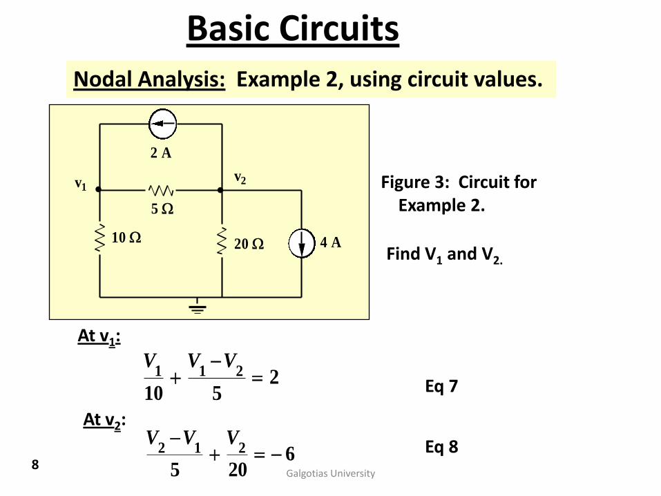
Nodal Analysis: Example 2, using circuit values.
v1v2
10
5
20 4 A
2 A
Figure 3: Circuit forExample 2.
Find V1 and V2.
At v1:
2510
211
VVV
At v2:
6205
212 VVV
Eq 7
Eq 8
Basic Circuits
8Galgotias University
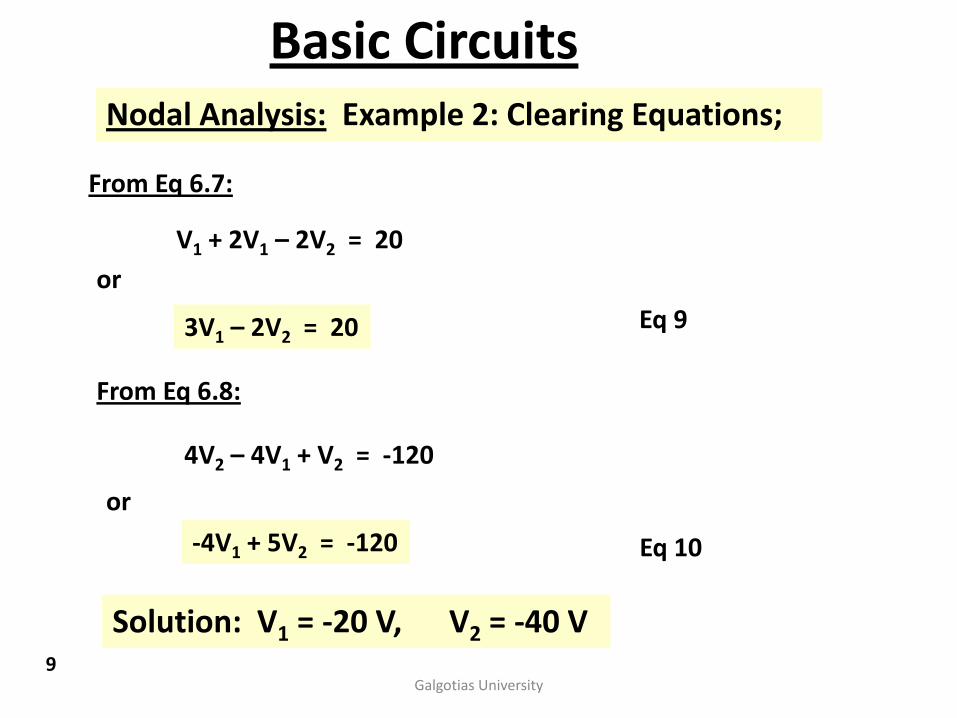
Nodal Analysis: Example 2: Clearing Equations;
From Eq 6.7:
V1 + 2V1 – 2V2 = 20
or
3V1 – 2V2 = 20
From Eq 6.8:
4V2 – 4V1 + V2 = -120
or
-4V1 + 5V2 = -120
Eq 9
Eq 10
Solution: V1 = -20 V, V2 = -40 V
Basic Circuits
9Galgotias University
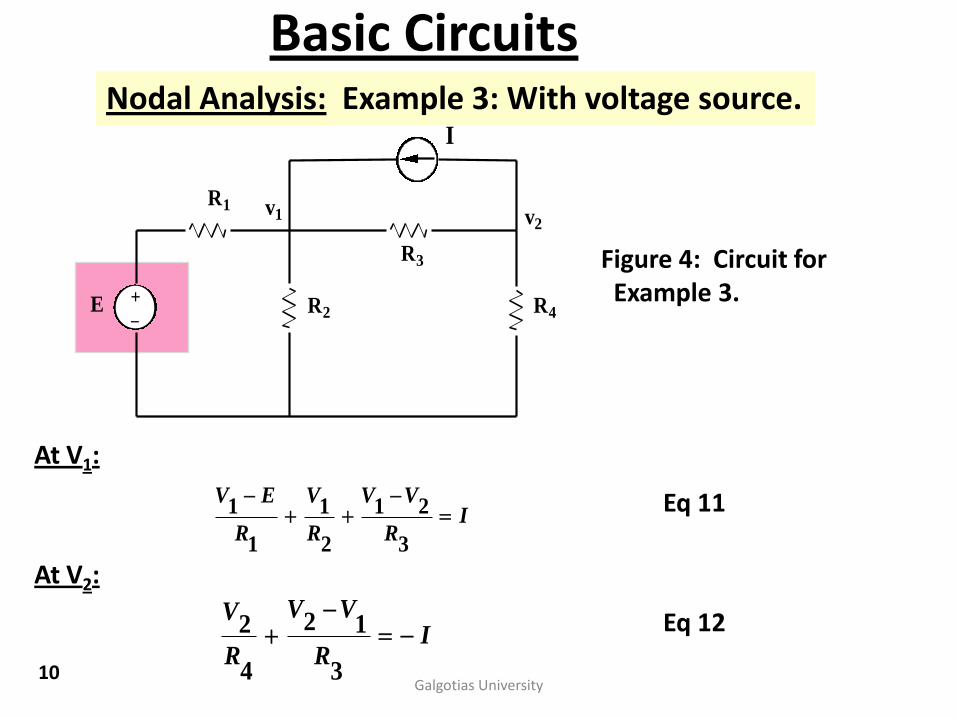
Basic CircuitsNodal Analysis: Example 3: With voltage source.
R1
R3
I
v2v1
+_ R2 R4E
Figure 4: Circuit forExample 3.
At V1:
IR
VV
R
V
R
EV
3
21
2
1
1
1
At V2:
IR
VV
R
V
3
12
4
2
Eq 11
Eq 12
10Galgotias University
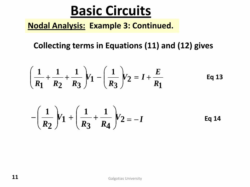
Basic CircuitsNodal Analysis: Example 3: Continued.
Collecting terms in Equations (11) and (12) gives
12
3
11
3
1
2
1
1
1
R
EIV
RV
RRR
IVRR
VR
2
4
1
3
11
2
1
Eq 13
Eq 14
11 Galgotias University
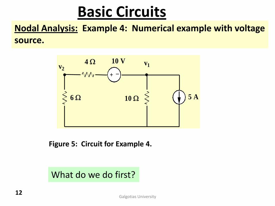
Basic CircuitsNodal Analysis: Example 4: Numerical example with voltagesource.
v2v1
6
4
10 5 A
+_
10 V
Figure 5: Circuit for Example 4.
What do we do first?
12Galgotias University
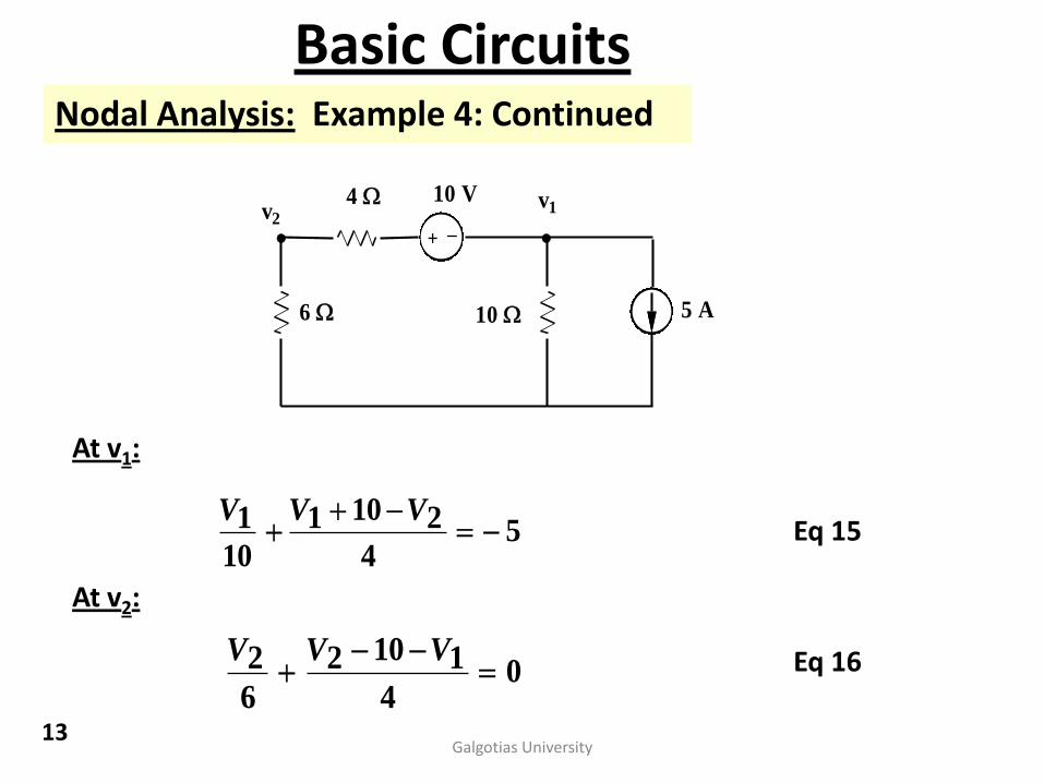
Basic CircuitsNodal Analysis: Example 4: Continued
v2v1
6
4
10 5 A
+_
10 V
At v1:
54
2101
10
1
VVV
At v2:
04
1102
6
2
VVV
Eq 15
Eq 16
13Galgotias University
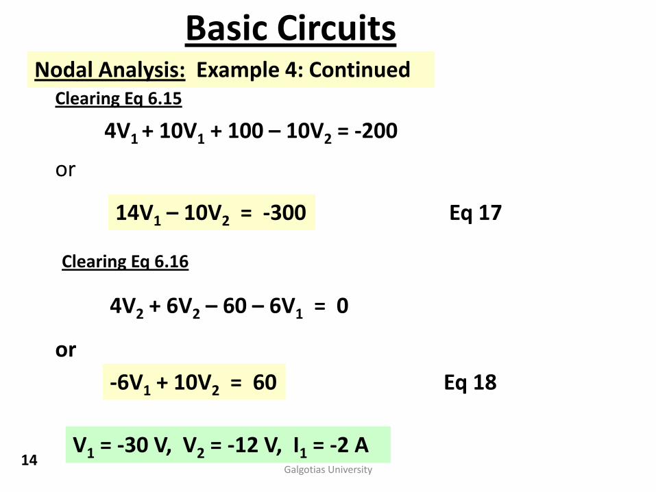
Basic CircuitsNodal Analysis: Example 4: Continued
Clearing Eq 6.15
4V1 + 10V1 + 100 – 10V2 = -200
or
14V1 – 10V2 = -300
Clearing Eq 6.16
4V2 + 6V2 – 60 – 6V1 = 0
or
-6V1 + 10V2 = 60
Eq 17
Eq 18
V1 = -30 V, V2 = -12 V, I1 = -2 A14
Galgotias University

Basic CircuitsNodal Analysis: Example 5: Voltage super node.
Given the following circuit. Solve for the indicated nodal voltages.
+_
6 A
5
4
2
10
v1v2 v3
10 V
x
x
xx
Figure 6: Circuit for Example 5.
When a voltage source appears between two nodes, an easy way to
handle this is to form a super node. The super node encircles the
voltage source and the tips of the branches connected to the nodes.
super node
15 Galgotias University

Basic CircuitsNodal Analysis: Example 5: Continued.
+_
6 A
5
4
2
10
v1v2 v3
10 V
At V1 62
31
5
21
VVVV
At super
node0
2
13
10
3
4
2
5
12
VVVVVV
Constraint Equation
V2 – V3 = -10 Eq 19
Eq 20
Eq 21
16 Galgotias University
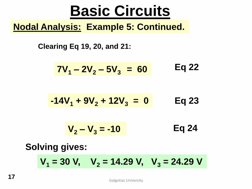
Basic CircuitsNodal Analysis: Example 5: Continued.
Clearing Eq 19, 20, and 21:
7V1 – 2V2 – 5V3 = 60
-14V1 + 9V2 + 12V3 = 0
V2 – V3 = -10
Eq 22
Eq 23
Eq 24
Solving gives:
V1 = 30 V, V2 = 14.29 V, V3 = 24.29 V
17Galgotias University
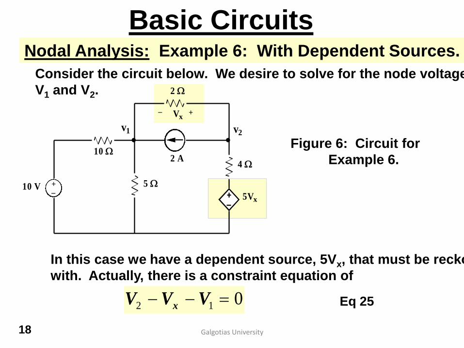
Basic CircuitsNodal Analysis: Example 6: With Dependent Sources.
Consider the circuit below. We desire to solve for the node voltages
V1 and V2.
10
2
4
5
2 A
+_10 V
5Vx
v1 v2
Vx+_
Figure 6: Circuit for
Example 6.
In this case we have a dependent source, 5Vx, that must be reckoned
with. Actually, there is a constraint equation of
012 VVV x Eq 25
18 Galgotias University

Basic CircuitsNodal Analysis: Example 6: With Dependent Sources.
10
2
4
5
2 A
+_10 V
5Vx
v1 v2
Vx+_
At node V1 22510
10 2111
VVVV
At node V2 24
5
2
212
xVVVV
The constraint equation: 21 VVVx 19
Galgotias University

Basic CircuitsNodal Analysis: Example 6: With Dependent Sources.
Clearing the previous equations and substituting
the constraint VX = V1 - V2 gives,
887
3058
21
21
VV
VV Eq 26
Eq 27
which yields,
VVVV 03.5,9.6 21
20Galgotias University


![Input/OUTPUT [ I/O Module structure ]. 2 Lecture Objectives I/O module External devices / Peripherals Structure of I/O I/O Techniques.](https://static.fdocuments.net/doc/165x107/56649e4e5503460f94b445d1/inputoutput-io-module-structure-2-lecture-objectives-io-module.jpg)


