Module 6: Solids Handling and...
69
Wastewater Treatment Plant Operator Certification Training Module 6: Solids Handling and Disposal This course includes content developed by the Pennsylvania Department of Environmental Protection (Pa. DEP) in cooperation with the following contractors, subcontractors, or grantees: The Pennsylvania State Association of Township Supervisors (PSATS) Gannett Fleming, Inc. Dering Consulting Group Penn State Harrisburg Environmental Training Center
Transcript of Module 6: Solids Handling and...
Wastewater Treatment Plant
Operator Certification Training
Module 6: Solids Handling and Disposal
This course includes content developed by the Pennsylvania Department of Environmental Protection (Pa. DEP) in cooperation with the following contractors, subcontractors, or grantees:
The Pennsylvania State Association of Township Supervisors (PSATS) Gannett Fleming, Inc.
Dering Consulting Group Penn State Harrisburg Environmental Training Center


MODULE 6: SOLIDS HANDLING AND DISPOSAL
Bureau of Water Supply and Wastewater Management, Department of Environmental Protection i Wastewater Treatment Plant Operator Training
Topical Outline
Unit 1 – Sludge Thickening I. Purpose of Sludge Thickening II. Gravity Thickeners III. Dissolved Air Flotation Thickeners IV. Centrifuge Thickeners V. Gravity Belt Thickeners Unit 2 – Anaerobic Digestion I. Purpose of Digestion
A. General Overview
B. How Digestion Works II. Components of an Anaerobic Digester System
A. Anaerobic Digester
B. Gas System III. Operations Overview of Anaerobic Digestion
A. Starting and Feeding a Digester
B. Mixing Tank Contents
C. Gas Production
D. Removing Tank Contents IV. Strategies for Maintaining an Anaerobic Digestion System
A. Test Interpretation and Controls
B. Checklists
C. Troubleshooting
D. Digester Cleaning
E. Cleaning Pipelines and Valves

MODULE 6: SOLIDS HANDLING AND DISPOSAL
Bureau of Water Supply and Wastewater Management, Department of Environmental Protection ii Wastewater Treatment Plant Operator Training
Unit 3 – Aerobic Digestion I. Aerobic Digestion
A. Overview
B. Comparisons between Anaerobic and Aerobic Digestion
C. Process Description
D. Operation
E. Records
F. Problems Unit 4 – Solids Management Planning I. Digested Sludge Handling
A. Overview
B. Drying Beds
C. Reed Beds
D. Lagoon
E. Mechanical Dewatering II. Sludge Disposal
A. Methods of Sludge Disposal
B. Regulations III. Review of Plans and Specifications
A. Items to Review
Bureau of Water Supply and Wastewater Management, Department of Environmental Protection 1-1 Wastewater Treatment Plant Operator Training
Unit 1 – Sludge Thickening
Learning Objectives
Describe the purpose of sludge thickening. List and describe the various methods used for sludge thickening.

PURPOSE OF SLUDGE THICKENING
Purpose of Sludge Thickening Solids from the primary clarifier (primary sludge) and secondary clarifier (secondary sludge) contain large volumes of water. This increased amount of water increases the overall volume of sludge that must be handled, increasing the size of the equipment, such as digesters, that must be installed. To decrease this volume, the sludge can be thickened. Essentially this results in an increase in the concentration of solids and a decrease in the total volume that must be handled in subsequent processes. There are several advantages to sludge thickening, including:
Improved digester performance due to a lower volume of sludge
Cost savings in the construction of new digestion facilities
Reduction in anaerobic digestion heating requirements since less water has to be heated Thickeners are installed prior to other solids handling processes such as anaerobic and aerobic digestion and dewatering. Caution should be taken to not thicken sludge to greater than 10% solids because it is difficult to pump sludges to the next treatment unit with a greater than 10% solids concentration.
Gravity Thickeners Gravity thickening of wastewater sludges uses gravity to separate solids from the sludges being treated. Solids that are heavier than water settle to the bottom of the thickener and are compacted by the weight of solids that continue to settle. The design of a gravity thickener is similar to a primary or secondary clarifier and consists primarily of:
Inlet and distribution assembly – introduces the sludge into the thickener
Sludge rake to move the sludge to a sludge hopper – slowly rotates to move the settled solids to the middle of the tank
Pickets or vertical steel members – provide gentle stirring or flocculation of the settled sludge and released trapped gas to prevent rising sludge
Effluent or overflow weir – collect and remove effluent or thickener overflow
Scum removal equipment – collect and remove floating debris
1-2 Bureau of Water Supply and Wastewater Management, Department of Environmental ProtectionWastewater Treatment Plant Operator Training

GRAVITY THICKENERS
Figure 1.1 Diagram of Gravity Thickener
The operation of gravity thickeners depends on the following factors:
Type of sludge
Age of the feed sludge
Sludge temperature
Sludge blanket depth
Solids and hydraulic detention times and loadings
Secondary sludges are not as well suited for gravity thickeners as primary sludges due to the large quantities of bound water that makes the sludge less dense than primary sludge solids. Bound Water is water contained within the cell mass of sludges or strongly held on the surface of colloidal particles, which is one of the causes of bulking sludge in the activated sludge process.
1-3 Bureau of Water Supply and Wastewater Management, Department of Environmental ProtectionWastewater Treatment Plant Operator Training

DISSOLVED AIR FLOTATION THICKENERS
Bureau of Water Supply and Wastewater Management, Department of Environmental Protection 1-4 Wastewater Treatment Plant Operator Training
The performance of a gravity thickener is controlled by:
The speed of the sludge collection mechanism
Adjusting the sludge withdrawal rate
Controlling the sludge blanket depth Typically the flow through a thickener is continuous and should be controlled as consistent as possible. Under normal operating conditions the surface water and effluent should be clear and free from solids and gas bubbles. The effluent is returned to the headworks of the plant for further treatment. The sludge blanket depth is usually kept around 5 to 8 feet and the speed of the sludge collectors should be fast enough to allow the settled solids to move toward the sludge collection sump, but not at a speed that will disrupt the settled solids. Typical loadings and output concentrations vary based on the sludge type and the operation of the thickener.
Sludge Type Solids Loading lbs/day/sq ft*
Thickened Sludge, %
Separate Primary 20 – 30 8 – 10 Activated Sludge 5 – 8 2 – 4 Trickling Filter 8 – 10 7 – 9 Combined Primary & Act Sl 6-12 4 – 9 Primary & Trickling
Filter 10 – 20 7 – 9
* lbs/day/sq ft X 4.883 = kg / day / sq m
Table 1.1 Operational and Performance Guidelines for Gravity Thickeners1 As with any wastewater treatment process, troubleshooting gravity thickeners starts with visual inspections as well as an understanding of the expected results by comparing design values with operating criteria. Performance can typically be determined by observing items such as liquid surface and effluent quality, as well as being aware of such things as uncharacteristic odors.
Dissolved Air Flotation Thickeners Air flotation thickeners separate solids by attaching air bubbles to suspended solids, causing the solids to move in an upward motion. This is accomplished using one of four methods: Dispersed air flotation using bubbles are generated by mixers or diffused air. Biological flotation where gases are formed by biological activity causing the solids to float. Dissolved air (vacuum) flotation where water is aerated at atmospheric pressure and released
under vacuum.

DISSOLVED AIR FLOTATION THICKENERS Dissolved air (pressure) flotation where air is put into solution under pressure and released at
atmospheric pressure. Dissolved air (pressure) flotation is the most common type of air floatation thickener.
Figure 1.2 Diagram of an air flotation thickener
The performance of these units depends on several factors, including:
Type of sludge
Age of the feed sludge
Solids and hydraulic loadings
Air to solids (A/S) ratio
Recycle rate
Sludge blanket depth
Primary sludges are not as easily thickened using air flotation thickeners, why?
_____________________________________________________________________________
If an air floatation thickener is used for primary sludges, some type of sludge collection device, such as a scraper (as shown in Figure 1.2), is typically located on the bottom of the tank to collect and periodically remove settled solids. As with the gravity thickener, troubleshooting air floatation thickeners starts with visual inspections as well as an understanding of the expected results by comparing design values with operating criteria. If problems are observed they may be related to the sludge blanket thickness, chemical conditioning, A/S ratio, recycle rate and/or solids or hydraulic loading.
Bureau of Water Supply and Wastewater Management, Department of Environmental Protection 1-5 Wastewater Treatment Plant Operator Training

CENTRIFUGE THICKENERS
Centrifuge Thickeners Centrifugal thickening results from sedimentation and high centrifugal forces. The sludge enters the centrifuge where the sludge is spun, separating the solids and liquid. The three basic types of centrifugal thickeners are: Basket centrifuges – a solid bowl that rotates along a vertical axis and operates in a batch manner. Scroll centrifuges – a solid bowl that rotates along a horizontal axis and operates in a continuous manner.
Figure 1.3 Diagram of a scroll centrifuge
Disc-nozzle type centrifuges – a solid bowl that rotates along a vertical axis and operates in a continuous manner. The use of the various centrifuges depends on costs, energy requirements, performance and alternative processes. The performance of centrifugal thickeners depends on several different factors:
Types of sludge – Primary sludges are not commonly thickened using centrifugal thickeners. Secondary sludges are more suited to centrifugal thickening because of their relative lack of stringy or bulky materials that may plug the centrifuge.
Age of the feed sludge
Solids and hydraulic loading
Bureau of Water Supply and Wastewater Management, Department of Environmental Protection 1-6 Wastewater Treatment Plant Operator Training

GRAVITY BELT FILTER THICKENERS
Bowl speed and resulting gravitational forces
Chemical conditioning When operating a centrifugal thickener, every attempt should be made to consistently feed fresh sludge into the thickener. The use of polymers may also enhance solids recovery when using a centrifugal thickener. In order to determine the correct polymer dosage, the operator may have to do some experimentation in order to get the best results and minimize chemical costs.
Gravity Belt Filter Thickeners The principle of a gravity belt filter thickener is similar to a gravity belt filter press, but does not incorporate any pressing action.
Figure 1.4 Diagram of a gravity belt thickener
Bureau of Water Supply and Wastewater Management, Department of Environmental Protection 1-7 Wastewater Treatment Plant Operator Training

GRAVITY BELT FILTER THICKENERS
Bureau of Water Supply and Wastewater Management, Department of Environmental Protection 1-8 Wastewater Treatment Plant Operator Training
Sludge that is to be thickened using a gravity belt filter thickener is first preconditioned, typically using polymer. The sludge is then applied to the gravity belt filter where free water drains through small openings in the belt filter as it travels the length of the belt. Once it is finished traveling along the length of the belt, it is removed and sent to the treatment plants next sludge treatment process or storage. Operators of gravity belt thickeners should be concerned with the filtrate quality and the dryness of the thickened sludge. The most frequent problem is washing out, which is when large volumes of water carry over with the thickened sludge due to improper belt drainage. Several items should be checked when washing out occurs:
Polymer dosage
Hydraulic loading
Solids loading
Belt speed
Belt washing equipment

KEY POINTS
Key Points for Unit 1 - Sludge Thickening
Sludge thickening removes some of the excess water from the influent resulting in better treatment efficiencies.
Care must be taken not to thicken the sludge to more than 10% solids which will create
difficulty in pumping sludge to the next treatment unit in the plant.
The primary types of sludge thickeners are: gravity thickeners, dissolved air flotation thickeners, centrifuge thickeners and gravity belt thickeners.
Gravity thickeners work well with primary sludge but secondary sludges are less dense and
do not work as well.
The three basic types of centrifugal thickeners are basket centrifuges, scroll centrifuges and disc-nozzle type centrifuges.
Centrifugal thickeners work well with secondary sludges because of their relative lack of
stringy or bulky materials that may plug the centrifuge.
The most frequent problem with gravity belt thickeners is washing out which is when large volumes of water carry over with the thickened sludge due to improper belt drainage.
Bureau of Water Supply and Wastewater Management, Department of Environmental Protection 1-9 Wastewater Treatment Plant Operator Training

EXERCISE
Exercise for Unit 1 – Solids Handling Matching – Match the gravity thickener parts (A-E) with their proper description (1-5): _____ 1. Collects and removes effluent or thickener overflow.
_____ 2. Slowly rotates to move the settled solids to the middle of the tank.
_____ 3. Introduces the sludge into the thickener.
_____ 4. Collects and removes floating debris.
_____ 5. Provides gentle stirring or flocculation of the settled sludge and releases trapped gas to prevent rising sludge.
A. Inlet and distribution assembly B. Scum removal equipment C. Effluent/Overflow weir D. Sludge rake to move the sludge to a hopper E. Pickets or vertical steel members
Multiple Choice – Choose the best answer unless otherwise noted: 6. Which of the following are advantages of sludge thickening? (Choose all that apply)
a. Cost savings in the construction of new digestion facilities b. Increased anaerobic digestion heating requirements, since more water has to be heated.
Improved digester performance due to a lower volume of sludge 7. The type of sludge that is commonly thickened using a centrifugal thickener is: (Choose one)
a. primary sludge b. secondary sludge
c. tertiary sludge
8. Sludge that is to be thickened using a gravity belt thickener is first preconditioned, typically using what? (Choose one)
a. chlorine b. lime
c. polymer d. soda ash
9. The sludge thickener diagrams that were viewed in this unit include which of the following? (Choose all that apply)
a. air floatation thickener b. scroll centrifuge thickener c. gravity belt thickener d. basket centrifuge thickener
Bureau of Water Supply and Wastewater Management, Department of Environmental Protection 1-10 Wastewater Treatment Plant Operator Training

Unit 2 - Anaerobic Digestion
Learning Objectives
Describe the purpose of digestion and how the anaerobic digestion process works. List the major components of an anaerobic digester and anaerobic digestion gas system. Describe the operational procedures for an anaerobic digester. Maintain proper records and complete applicable calculations for an anaerobic digester. Perform proper maintenance on an anaerobic digestion system.
Bureau of Water Supply and Wastewater Management, Department of Environmental Protection 2- Wastewater Treatment Plant Operator Training
1

PURPOSE OF DIGESTION
Bureau of Water Supply and Wastewater Management, Department of Environmental Protection 2- Wastewater Treatment Plant Operator Training
2
General Overview
Anaerobic digestion is the breakdown of complex wasted sludge in the absence of oxygen. In wastewater treatment, waste sludge is collected in a tank and conditions are provided such that saprophytic bacteria and methane forming bacteria are fostered. The saprophytic bacteria transform the complex solids into volatile acids that the methane forming bacteria further process into gasses and water.1
The anaerobic digestion process serves the following purposes in the treatment of sludge: Volatiles solids are reduced by 35 – 50%. Total solids are reduced by 30 – 60%. Pathogens are reduced by 85 – 99%. Dewatering properties are enhanced. These are important characteristics that create a waste that is better for disposal or beneficial use (reduced volume through dewatering, reduced pathogens and a more stabilized product through the reduction of volatile solids).
25 Lbs
75 Lbs
Before digestion of 100 pounds of sludge: 75%
Volatile, 25% Fixed Solids.
After a 65% reduction in Volatile Solids there is less
sludge remaining to process.
25 Lbs
25 Lbs
50 Lbs of CH4, CO2, H2O
25 Lbs
75 Lbs
Before digestion of 100 pounds of sludge: 75%
Volatile, 25% Fixed Solids.
25 Lbs
75 Lbs
25 Lbs
75 Lbs
Before digestion of 100 pounds of sludge: 75%
Volatile, 25% Fixed Solids.
After a 65% reduction in Volatile Solids there is less
sludge remaining to process.
25 Lbs
25 Lbs
50 Lbs of CH4, CO2, H2O
After a 65% reduction in Volatile Solids there is less
sludge remaining to process.
25 Lbs
25 Lbs
50 Lbs of CH4, CO2, H2O
25 Lbs
25 Lbs
25 Lbs
25 Lbs
50 Lbs of CH4, CO2, H2O
50 Lbs of CH4, CO2, H2O
Figure 2.1 Diagram of solids reduction due to anaerobic digestion
Dewaterable is a physical property generally taken to be the ability of a liquid to separate from the surrounding solid with or without chemical conditioning. A material is considered dewaterable if water will readily drain from it.2

PURPOSE OF DIGESTION
Bureau of Water Supply and Wastewater Management, Department of Environmental Protection 2- Wastewater Treatment Plant Operator Training
3
How Digestion Works
Once sludge is fed into the digester, acid forming bacteria begin to break down the long-chain molecules (carbohydrates, fats, and proteins) into simpler compounds that are used as a food source by the methane forming bacteria. The methane formers break the material simpler compounds into a simpler form that can be disposed of safely. In addition, enzymes, which are a by-product of the bacteria in the sludge, help the bacteria break down the solids. Below is a diagram of the process. The top row is the acid forming reactions. The bottom row is the methane fermentation reactions.
Raw Sludge –Complex Substrate
CarbohydratesFats
Proteins
Microorganisms“A”
Principally Acid Formers
CO2 , H2O.Intermediate Degradation
Products
Organic Acids,Cellular and Other
Intermediate Degradation
Products
Organic Acids,Cellular and Other
Intermediate Degradation
Products
Microorganisms“B”
PrincipallyMethaneFormers
CH4
Methane
Other End Products –H2O, H2S
andDegradation
Products
CO2
CarbonDioxide
Figure 2.2 Diagram of reactions in a digester3 Digesters can be operated in three different temperature ranges. These can be thought of as the cold, warm and hot digesters. The cold digesters use psychrophilic (cold loving) bacteria. The warm digesters use mesophilic (medium temperature loving) bacteria. The hot digesters use thermophilic (hot loving) bacteria.

PURPOSE OF DIGESTION
Bureau of Water Supply and Wastewater Management, Department of Environmental Protection 2- Wastewater Treatment Plant Operator Training
4
Table 2.1 Temperature ranges and days for digestion
Bacteria Temperature Range (F) Days for Digestion Psychrophilic 50 - 68 50 - 180
Mesophilic 68 – 113 25 – 30 Thermophilic 113 – 140 5 - 12
Approximately ninety percent of anaerobic digesters use mesophilic bacteria. The optimum operating temperature for an anaerobic digester using mesophilic bacteria is 90 – 100 degrees. Acid Forming Reactions Acid forming reactions break down the complex “foods” in the sludge into simpler molecules. Of the two types of reactions, acid forming and methane fermentation, acid forming is the more robust. This means that acid forming bacteria will tolerate a wider range of environmental conditions such as temperature and pH. In addition, acid formers have the capacity to reproduce at a faster rate than methane formers. Saprophytic organisms do the majority of the digestion during acid forming reactions.
Saprophytic organisms live on dead or decaying organic matter. They are part of the natural decomposition of organic solids in wastewater4.

PURPOSE OF DIGESTION
Bureau of Water Supply and Wastewater Management, Department of Environmental Protection 2- Wastewater Treatment Plant Operator Training
5
Methane Fermentation Reactions Methane fermentation reactions finish digesting the simpler molecules produced by the acid forming reactions. Compared to acid formers, methane formers do not tolerate as wide a range of environmental conditions. In addition, methane formers do not reproduce as quickly as acid formers. This is important because acid formers and methane formers must be kept in balance for the digestion process to work properly. Methane fermentation reactions produce methane gas which that is used as an energy source for heating the digester.
Growth Rates
Acid Formers Methane Formers
pH
7
pH
77
Figure 2.3 Diagram of how bacteria growth rates are affected by pH

COMPONENTS OF AN ANAEROBIC DIGESTER SYSTEM
Anaerobic Digester
Tank Shapes There are three common types of Anaerobic Digester tanks: Rectangular. Low cost to build. Have “dead” areas within the tank that are difficult to mix. Cylindrical. Contain a conical bottom. Reduces the number of “dead” areas, or difficult areas to
mix, within the tanks that are difficult to mix. Egg-Shaped. More expensive to build than the other types of tanks. They have better heat
retention because there is more volume per surface area. Because of the design, a better suspension of solids is maintained during mixing. They have the least amount of “dead” area within the tank that is difficult to mix.
Figure 2.4 Photo of Egg-Shaped Digesters5
Draft Tube
Maximum Fill for Sludge
Gas Collection Area
Figure 2.5 Cross-Section of an Egg-Shaped Digester6
Bureau of Water Supply and Wastewater Management, Department of Environmental Protection 2- Wastewater Treatment Plant Operator Training
6

COMPONENTS OF AN ANAEROBIC DIGESTER SYSTEM
Bureau of Water Supply and Wastewater Management, Department of Environmental Protection 2- Wastewater Treatment Plant Operator Training
7
Fixed Cover Digesters Rectangular, cylindrical, and egg-shaped digesters may all have a fixed cover. Because a fixed cover can not adjust to positive or negative pressures within the tank, a fixed cover digester has a limited range of gas volume that it can store. This requires that the pressure inside a fixed cover digester be monitored to ensure that positive or negative pressures do not damage the tank.
Figure 2.6 Fixed Cover Digester
Part Purpose Sludge Feed Conveys sludge to digester for treatment Draft Tube Directs mixture of raw and digested sludge to heating region Gas Injectors Inject gas into sludge to mix sludge and increase heat transfer Hot Water Jacket Contains hot water that heats sludge Deflection Shield Deflects heated sludge throughout digester Gas Mixer Pumps gas from gas draw-off to gas injectors Gas Draw-Off Draws gas from top of digester to gas system Hot Water Piping Conveys hot water from heat exchanger to hot water jacket Sludge Draw-Off Removes digested sludge from bottom of digester Supernatant Draw-Off Tubes
Draw off supernatant from various levels in digester
Supernatant Box Collects supernatant for transport to headworks or primary clarifier influent The components listed may be installed differently in different types of digesters. As an example, a rectangular digester may have multiple draft tubes for mixing.

COMPONENTS OF AN ANAEROBIC DIGESTER SYSTEM
Bureau of Water Supply and Wastewater Management, Department of Environmental Protection 2- Wastewater Treatment Plant Operator Training
8
Floating Cover Digesters Cylindrical digesters may have a floating cover. Floating cover digesters are preferred for gas storage and safety. Because a floating cover can adjust to positive and negative pressures within the tank, a floating cover digester can accommodate a wider range of gas storage requirements. However, it is still important to monitor the pressure inside a floating cover digester to ensure that positive or negative pressures do not damage the tank. Floating cover digesters have the following advantages: Better scum blanket control Less likely to damage the digester under high rates of withdrawal Better gas storage Larger storage volume Better barrier between methane and atmosphere Better pressure control
COMPONENTS OF AN ANAEROBIC DIGESTER SYSTEM
Bureau of Water Supply and Wastewater Management, Department of Environmental Protection 2- Wastewater Treatment Plant Operator Training
9
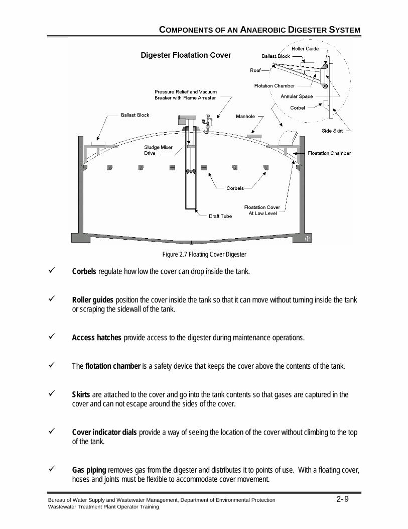
Figure 2.7 Floating Cover Digester
Corbels regulate how low the cover can drop inside the tank. Roller guides position the cover inside the tank so that it can move without turning inside the tank
or scraping the sidewall of the tank. Access hatches provide access to the digester during maintenance operations. The flotation chamber is a safety device that keeps the cover above the contents of the tank. Skirts are attached to the cover and go into the tank contents so that gases are captured in the
cover and can not escape around the sides of the cover. Cover indicator dials provide a way of seeing the location of the cover without climbing to the top
of the tank. Gas piping removes gas from the digester and distributes it to points of use. With a floating cover,
hoses and joints must be flexible to accommodate cover movement.

COMPONENTS OF AN ANAEROBIC DIGESTER SYSTEM
Bureau of Water Supply and Wastewater Management, Department of Environmental Protection 2- Wastewater Treatment Plant Operator Training
10
Water Seal The water seal creates a movable high point so that gases do not escape and pressure inside the tank can be moderated. Both fixed and floating cover tanks have a water seal, however, because a floating cover is movable, it can accommodate a wider range of gas volumes and pressure.
Figure 2.8 Water Seal on a Floating Cover Digester
Parts Purpose Water Seal Prevents air from entering digester or gas from escaping. Prevents development
of explosive conditions. Vacuum Relief Relieves excessive vacuums so digester cover will not collapse Pressure Relief Relieves excessive pressures in digester so water seal will not be blown out. Flame Arrester Prevents spark or flame from entering digester Sediment Trap Traps sediment in digester gas Condensate Drain Drains condensate removed from digester gas Gas Piping Conveys digester gas from digester to heaters, mixers or waste gas burners

COMPONENTS OF AN ANAEROBIC DIGESTER SYSTEM
Bureau of Water Supply and Wastewater Management, Department of Environmental Protection 2- Wastewater Treatment Plant Operator Training
11
Digester Mixing Mixing the contents of the digester keeps the particles within the sludge from settling. It also keeps the sludge at a uniform temperature. There are two types of digester mixing: Gas Mixing. Refer to Figure 1.6. When gas mixing is utilized, gas is pulled from the tank,
compressed, and discharged through gas outlets within the digester. As the gas rises to the surface, it carries sludge with it, creating a rolling action inside the tank.
A large flat bottom digester may have a grid of six to eight air tubes injected with gas to mix a localized zone of the tank.
Mechanical Mixing. Mechanical mixers use propellers to mix the sludge. These are normally found
on fixed cover digesters. Mechanical mixing has the advantage of being less maintenance intensive and less dependent on liquid levels. However, if the propeller is located inside the draft tube, then liquid levels must be maintained so that sludge can be pulled in the top of the draft tube and forced out the bottom. Small units and egg digesters have one central mixer. Large units have a grid pattern of mixers.
Figure 2.9 Propeller Mixer Digester Heating The digester is heated because the time to digest the solids is shorter in a warm environment. Most digesters are heated with methane, electric strip heaters, natural gas, or fuel oil. The digester heater is located close to the digester to minimize heat loss. The most cost effective method for heating the digester is to use methane produced by the methane fermentation reactions inside the digester. Heat from the methane can be transferred to the sludge inside the digester through sidewall pipes, a heat exchanger, or direct steam.

COMPONENTS OF AN ANAEROBIC DIGESTER SYSTEM
Bureau of Water Supply and Wastewater Management, Department of Environmental Protection 2- Wastewater Treatment Plant Operator Training
12
Sampling Well The purpose of the sampling well is to allow quick access to the digester. This allows the operator to: Check the height of the liquid Check the depth of the scum layer Sample the mixed liquor The sampling well is located in the digester cover. It should only be opened for a short amount of time. It should be securely sealed when not in use.
Supernatant is the liquid removed from a system once the system has been allowed to have the heavier particles settle. In the process of digestion it is the liquid between the scum layer and the sludge solids. It is usually recycled to the head of the plant10.
Supernatant Tubes Supernatant tubes allow the operator to determine where clarified liquids should be withdrawn.
Figure 2.10 Supernatant Tubes and Box

COMPONENTS OF AN ANAEROBIC DIGESTER SYSTEM
Bureau of Water Supply and Wastewater Management, Department of Environmental Protection 2- Wastewater Treatment Plant Operator Training
13
Sludge Draw-Off Lines Sludge is removed from the digester through the draw-off lines for use “as-is” for land application, or for further processing through a drying bed, centrifuge, plate press or belt filter press. Sludge should not be left in the sludge draw-off lines and isolated by closing the valves on each end for several days since the production of gas can generate sufficient pressure to rupture the line.
Gas System The anaerobic digestion process produces twelve to eighteen cubic feet of gas for every pound of volatile matter destroyed. The gas system removes the gas from the digester. The following items are components of the gas system:
Figure 2.11 Single Digester Gas Handling System Gas Dome The gas dome is the collection point and storage area for gas before it is withdrawn from the digester. It is located on the top of the digester. Refer to Figure 2.8. Relief Valve The relief valve will provide pressure relief if pressure inside the digester is too high or too low. It helps protect the digester, digester cover, and downstream equipment. The relief valves are located near the gas dome, near the pressurized storage areas, and where the gas is burned or wasted. Refer to Figure 2.8. Flame Arrester If there is a fire in the piping system, the flame arrester will dissipate the heat and stop the flame. It is located at the plant flare and wherever gas is ignited. Refer to Figure 2.8.

COMPONENTS OF AN ANAEROBIC DIGESTER SYSTEM
Bureau of Water Supply and Wastewater Management, Department of Environmental Protection 2- Wastewater Treatment Plant Operator Training
14
Thermal Valve If there is a fire in the piping system, the thermal valve will stop the flow of gas. It is located near the flame source and near the gas dome. Flame Trap Assembly A flame trap assembly is a flame arrester and thermal valve in one unit. If there is a fire in the piping system, a flame trap assembly will stop the flame and cut the gas flow. The flame trap assembly is located near the flame source. Refer to Figure 2.11. Drip Trap A drip trap removes impurities from the methane gas flow. A drip trap must be checked on a routine basis. The drip trap is located out in the open where the pipe has had a chance to come to ambient temperature. Refer to Figure 2.11. Failure to check the drip trap could lead to damaged equipment, reduced BTU levels, and corrosive liquids in the pipes. Sediment Trap A sediment trap removes impurities from the methane gas flow. It should be drained frequently—twice a day during cold weather. Sediment traps should be placed near the sediment source, such as the gas dome. Refer to Figure 2.11. Failure to drain the sediment trap could lead to damaged equipment, reduced BTU levels, and corrosive liquids in the pipes. Gas (Flow) Meters A gas meter measures the volume of gas taken from the digester. The gas meters are located near the sites where the gas is utilized. If there is a decrease in gas production, the digester may be going sour. Refer to Figure 2.11.
Which types of meters have worked the best? _______________________________________________________________________________________________________________________________________________________________________________________________________________________________________________________________
What type of meters do people in the class use? _______________________________________________________________________________________________________________________________________________________________________________________________________________________________________________________________

COMPONENTS OF AN ANAEROBIC DIGESTER SYSTEM
Bureau of Water Supply and Wastewater Management, Department of Environmental Protection 2- Wastewater Treatment Plant Operator Training
15
Pressure Regulators A pressure regulator regulates gas pressure to provide a consistent and uniform feed pressure of methane gas to its various end uses. The pressure regulator is located near the end use of the gas. It should be protected by a thermal valve. Refer to Figure 2.11. Waste Gas Burner A waste gas burner burns excess methane gas. It should be located a safe distance from the digester. The actual distance will vary by facility, depending on site topography, normal wind directions, and plant design. Refer to Figure 2.11.
How do you check your waste gas burners? _______________________________________________________________________________________________________________________________________________________________________________________________________________________________________________________________
Does anyone have any tips for checking waste gas burners? _______________________________________________________________________________________________________________________________________________________________________________________________________________________________________________________________

OPERATIONS OVERVIEW OF ANAEROBIC DIGESTION
Bureau of Water Supply and Wastewater Management, Department of Environmental Protection 2- Wastewater Treatment Plant Operator Training
16
Starting and Feeding a Digester
Starting the Digester A digester can be started naturally by allowing the existing organisms in the sludge to grow, or a digester can be seeded (inoculation) with sludge from another digester. Using seed sludge speeds the process of starting a digester because the correct organisms are quickly introduced into the digester. During the startup the first reactions that have to occur are the breaking down of the complex substrates to acids, alcohols and similar simpler compounds. This is followed by an acid regression stage prior to reaching a stable balance between the acid formers and the methane producers.
To inoculate a digester is to introduce a seed culture into the system7.
Seed sludge is the contents from a viable digester that is transferred to a new or ailing digester to jump start the biological activity in the latter unit8.
The acid regression stage is a point in the process at which time the ammonia produced in the digester stops the pH from decreasing further and starts to raise the pH9.
Feeding the Digester The digester is fed from several locations throughout the plant. While feeding the digester, digester volume and pressure should be carefully monitored to ensure that both stay within the capacity of the digester. In addition, contents fed to the digester and the acid forming reactions within the digester affect the temperature, pH, and alkalinity of the sludge. If the temperature, pH, population of acid formers, or alkalinity of the sludge swings out of range, the acid forming reactions and the methane fermentation reactions may become out of balance, causing the digestion process to fail. A digester should be fed often—normally from two to twenty times per day. Frequent feeding and withdrawal will avoid overloading downstream processes.

OPERATIONS OVERVIEW OF ANAEROBIC DIGESTION
Bureau of Water Supply and Wastewater Management, Department of Environmental Protection 2- Wastewater Treatment Plant Operator Training
17
The three main items fed to the digester are as follows: Raw (Primary) sludge has had little or no treatment since it is from the primary clarifier. It is a good
food source, therefore, it has a high reduction potential. However, it also contains a large amount of non-digestible material such as grit and rags. Because of the amount of grit and other non-digestible material in the sludge, raw sludge can consume digester volume from the bottom up.
Scum is the floatable portion of the flow stream. It can be found in the preliminary or primary units.
Some plants remove scum from the primary clarifier and place it in a scum concentrator before sending it to the digester. Other plants may dispose of the scum through other methods. Scum can consume digester volume from the top down.
Waste activated sludge is drawn from the bottom of the secondary clarifier. This provides the sludge
used in feeding the digester. It can be pre-thickened, and has a high percentage of volatile solids; however, it has a lower percentage of volatile suspended solids reduction.
It is best to feed a digester thickened sludge because thickened sludge has the following benefits: Requires less heat. Increases the food per unit volume of sludge pumped. Lessens the impact of alkalinity swings. Reduces the return hydraulic load.

OPERATIONS OVERVIEW OF ANAEROBIC DIGESTION
Bureau of Water Supply and Wastewater Management, Department of Environmental Protection 2- Wastewater Treatment Plant Operator Training
18
Mixing Tank Contents
Digester contents are mixed by either mechanical or gas methods. Facilities that have primary and secondary digesters will normally keep the primary digester on at all times. This provides for an even distribution of raw sludge, organisms, alkalinity, and heat in the primary digester. It also prevents the buildup of a scum blanket and grit deposits. In the primary digester, the contents are mixed for seven to thirty days then pumped to the secondary digester for fourteen to forty-five days
Gas Production As the contents of the tank are mixed, the methane formers begin to create methane gas. Methane is the most useful gas that is produced and is often used to heat the digester. It should be 65% - 70% of the gas produced in the digester. To avoid damaging a digester, it is important to monitor the pressure inside a digester. In addition, methane gas inside a digester is very explosive, especially if mixed with air from the outside. Refer to page 164 of Chapter 12 in Operation of Wastewater Treatment Plants, Volume II.
Removing Tank Contents
Supernatant is the liquid removed from a system once the system has been allowed to have the heavier particles settle. In the process of digestion it is the liquid between the scum layer and the sludge solids. It is usually recycled to the head of the plant10.
Positive pressure is pressure that is greater than the local atmospheric pressure. Atmospheric pressure at sea level is about 14.7 psi or 760 torr. Hence any pressure above this would be a positive pressure. The atmospheric pressure will vary with the weather conditions and elevation11.
Supernatant should be removed on a daily basis. Sludge can be withdrawn before or after the supernatant. For facilities with primary and secondary digesters, the supernatant and sludge is removed from the secondary digester. It should be done at a slow enough rate that a positive pressure is maintained inside the tank. It usually requires that the mixer be shut off for six to twelve hours.

STRATEGIES FOR MAINTAINING AN ANAEROBIC DIGESTION SYSTEM
Test Interpretation and Controls
An anaerobic digester requires careful monitoring to ensure successful operation. Below is a list of items that should be checked. Temperature Temperature within the digester should be checked at least once a day. It should not fluctuate more than 1 degree per day. The temperature range should be 90–100 degrees. Acid-Alkalinity Relationship It is important to watch the alkalinity and match the alkalinity with acids. The acid-alkalinity relationship gives the first warning that there is a problem with the digester. The following chart outlines the effect of the volatile acids (V.A.) to alkalinity (ALK) ratio on the digester.
Optimum V.A./ALK = .05 - 0.1 Stress V.A./ALK = 0.3 - 0.4 Deep Trouble V.A./ALK = 0.5 - 0.7 Failure V.A./ALK = 0.8 and above
Digester Gas Once the digester is running, the gas produced will be 30% - 35% CO2, and the rest will be mostly methane. If the CO2 level exceeds 45%, the gas will not be burnable. pH Supernatant pH should be about neutral (7). The supernatant pH will be one of the last indicators that something is wrong.
Bureau of Water Supply and Wastewater Management, Department of Environmental Protection 2- Wastewater Treatment Plant Operator Training
19

STRATEGIES FOR MAINTAINING AN ANAEROBIC DIGESTION SYSTEM
Bureau of Water Supply and Wastewater Management, Department of Environmental Protection 2- Wastewater Treatment Plant Operator Training
20
Solids Test Samples should be collected of the raw sludge, recirculated sludge, and supernatant. Each sample should be tested for total solids and volatile solids. Among other things, this information is used to determine the reduction of volatile solids, and the amount of solids in the digester. Records During digester operation, the following information must be recorded12: Raw sludge and thickened waste activated sludge sent to digesters
Volume, gallons per day
pH
Total solids, %
Volatile solids, % Digester gas
Total production, cubic feet per day
Carbon dioxide, % Digested sludge (mixed digester contents)
Volatile acids, mg/L
Alkalinity, mg/L
Total solids, %
Volatile acids, %
pH

STRATEGIES FOR MAINTAINING AN ANAEROBIC DIGESTION SYSTEM
Bureau of Water Supply and Wastewater Management, Department of Environmental Protection 2- Wastewater Treatment Plant Operator Training
21
Sludge removed (mixed digester contents)
Volume, gallons per day
Total solids, %
Volatile solids, % On the next page is a sample digestion bench sheet. A bench sheet provides a central location to compile data specific to a process.

Bureau of Water Supply and Wastewater Management, Department of Environmental Protection 2-
STRATEGIES FOR MAINTAINING AN ANAEROBIC DIGESTION SYSTEM
Wastewater Treatment Plant Operator Training
22
Monthly Record July 2003
RemarksG
allo
ns p
er
Day
% S
olid
s
% V
ola
tile
pH Scu
m
Gal
/Da
y
Tem
p (F
)
% S
olid
s
pH Vol
. Aci
ds
mg
/l
Alk
alin
ity
mg
/l
Aci
ds to
A
lkal
inity
Mix
ing
hr.
Gas
Pro
d.
C
u.F
t./D
ay
Cu
.Ft/M
G
Flo
w
% C
O2
Gal
. To
Be
d
Bed
No.
% S
olid
s
% V
ola
tile
Lbs.
Dry
S
olid
s
Cu.
Yd.
Cak
e R
em
ove
d
1 Tue 12,850 2.4 80.7 5.9 91 1.3 6.9 103 1450 0.071 24 31080 17.442 Wed 12,280 1090 91 24 37170 15.843 Thu 11,990 91 24 26800 12.384 Fri 12,020 91 24 28900 14.365 Sat 11,460 3.1 73.5 6 1700 91 2.8 6.8 137 1400 0.098 24 28320 11.41 416 Sun 11,720 91 24 28710 12.037 Mon 11,990 91 24 25580 128 Tue 13,090 3.4 73.1 5.9 91 1.6 6.9 86 1690 0.051 24 24310 13.02 399 Wed 11,170 1190 92 24 24550 9.32
10 Thu 11,000 92 24 24550 10.6411 Fri 12,000 92 24 24550 11.1712 Sat 11,490 3.5 83.4 5.7 720 92 1.6 6.9 69 1700 0.041 24 25640 11.6413 Sun 12,000 92 24 25940 11.9114 Mon 11,760 740 93 24 28750 14.33 3915 Tue 12,460 3.8 79.2 5.9 93 1.6 6.8 86 1790 0.048 24 31450 16.1916 Wed 11,820 540 93 24 34150 13.8617 Thu 12,280 93 24 32550 14.0218 Fri 11,440 93 24 28400 10.8819 Sat 11,560 1.3 81.7 6.3 580 94 1.4 6.9 120 1610 0.075 24 27900 11.36 3920 Sun 12,070 94 24 31000 12.4121 Mon 11,960 94 24 32380 14.6322 Tue 12,510 850 94 24 34420 18.33 3223 Wed 12,180 1.9 75.3 94 1.3 86 1280 0.067 24 37810 13.03 pH probe not working24 Thu 10,560 94 24 37430 15.9525 Fri 11,870 94 24 37560 15.5126 Sat 11,430 2.9 70.6 94 1.4 24 37030 14.45 pH probe not working27 Sun 11,510 1150 94 24 35320 14.5528 Mon 11,840 2.9 73.2 6.1 94 1.5 6.8 120 1670 0.072 24 31150 14.5 3329 Tue 12,120 650 94 24 29520 15.8530 Wed 11,700 4.6 77.7 6.2 94 1.5 6.9 120 1400 0.086 24 32860 11.9731 Thu
356,130 29.8 768.4 48 9210 2781 16 55 927 13,990 0.608 720 915,780 405 22313,090 4.6 83.4 6.3 1700 94 2.8 6.9 137 1,790 0.098 24 37,810 18.33 4110,560 1.3 70.6 5.7 540 91 1.3 6.8 69 1,280 0.041 24 24,310 3211,871 2.98 76.84 6 921 92.7 1.6 6.9 103 1,554 0.068 24 30,526 13.06 37Avg
Operators:
Oakhills, PAWilliam Clinton PCF
Dat
e
Day
Raw Sludge Recirculated Sludge Gas Sludge Disposal
DIGESTION
TotalMaxMin
Figure 2.12 Digestion Bench Sheet

STRATEGIES FOR MAINTAINING AN ANAEROBIC DIGESTION SYSTEM
Bureau of Water Supply and Wastewater Management, Department of Environmental Protection 2- Wastewater Treatment Plant Operator Training
23
Total Sludge vs Volatile
300
400
500
600
all
on
s
70
72
74
76
78
80
82
84
% V
ola
tile
0
100
200
1 3 5 7 9 11 13 15 17 19 21 23 25 27 29 31
1,00
0 G
Sludge to Digesters
Volatile to Digesters
Volatile Acid to Alkalinity
0.05
0.055
0.06
0.065
0.07
0.075
0.08
0.085
0.09
0.095
0.1
1 2 3 4 5 6 7 8 9 10 11 12 13 14 15 16 17 18 19 20 21 22 23 24 25 26 27 28 29 30 31
Figure 2.13 Total Feed Sludge and Percent Volatile Solids13
Volatile Acid to Alkalinity
Figure 2.14 Volatile Acids to Alkalinity Ratio14

STRATEGIES FOR MAINTAINING AN ANAEROBIC DIGESTION SYSTEM
Bureau of Water Supply and Wastewater Management, Department of Environmental Protection 2- Wastewater Treatment Plant Operator Training
24
Volume of Sludge There is a requirement to track the volume of sludge pumped per day. It is tracked to calculate the amount of sludge going to downstream processes and to ultimate disposal. The volume of solids is calculated using the volume of suspended solids and the percent solids in the suspension. In rough numbers you can create for your facility an approximation of how much biomass will be created by removing a specified amount of BOD and Total Solids Suspension (TSS). The TSS would be a rougher estimate than the calculation of volume times the percent solids. Refer to page 196, Example 4 of Chapter 12 in Operation of Wastewater Treatment Plants, Volume II. Raw Sludge To track how much material is being fed to the digester, the amount of sludge and scum has to be added together. The sludge numbers provide an indication of gas production (the volatile fraction) and the volume of solids that will be remaining in the digester. These numbers have an impact on the retention time in the digester as well as the operating level in the tank. Refer to page 197, Example 5 of Chapter 12 in Operation of Wastewater Treatment Plants, Volume II. Computing Digester Loadings The return of supernatant to the wet side of the plant can cause disturbances in those processes if the treatment load is too high. Therefore, the amount of solids being returned should be tracked. This also serves as a guide as to when to adjust the withdrawal tubes so that the most clarified supernatant is being removed from the digester. Refer to page 198, “J. Digester Supernatant” of Chapter 12 in Operation of Wastewater Treatment Plants, Volume II. The first step in the process is to figure out how much good stuff you are sending to the unit. This is the food feeding ratio, or the amount of Volatile Matter to the current content volume of the tank. Refer to page 198, “K. Computing Digester Loadings” of Chapter 12 in Operation of Wastewater Treatment Plants, Volume II. Computing Gas Production The gas production is not really computed but is directly read from the meter. Unfortunately, that number by itself does not help in operating the facility. However, if it is related to other factors such as the amount of volatile matter destroyed or the amount fed, then it can be a reliable number. Refer to page 199, “L. Computing Gas Production” of Chapter 12 in Operation of Wastewater Treatment Plants, Volume II.

STRATEGIES FOR MAINTAINING AN ANAEROBIC DIGESTION SYSTEM
Bureau of Water Supply and Wastewater Management, Department of Environmental Protection 2- Wastewater Treatment Plant Operator Training
25
Solids Balance You need to track where the solids are going. Some will remain as a solid (all of the fixed portion and some of the volatile), some will be converted to liquid and some with will leave as a gas. If you can match up your total pounds in to the total pounds out of the digestion system you have a good handle on the operation of the system. Refer to page 197, “G. Raw Sludge” of Chapter 12 in Operation of Wastewater Treatment Plants, Volume II. Refer to page 198, “I. Secondary Digester Sludge” of Chapter 12 in Operation of Wastewater Treatment Plants, Volume II. Refer to page 199, “M. Solids Balance” of Chapter 12 in Operation of Wastewater Treatment Plants, Volume II. Other Calculations Refer to page 197, “H. Recirculated Sludge” of Chapter 12 in Operation of Wastewater Treatment Plants, Volume II. Refer to page 199, “N. Other Computations” of Chapter 12 in Operation of Wastewater Treatment Plants, Volume II.
Checklists Checklists serve as reminders. They can and should be modified to reflect the conditions and situations at each plant. For sampling and other data collection the bench sheets sometimes constitute the checklist or the checklist is used to develop the bench sheets. Refer to pages 204 – 206 of Chapter 12 in Operation of Wastewater Treatment Plants, Volume II. On these three pages are two checklists to use on a daily, weekly, monthly, or six month basis. These checklists are: Operation and Maintenance Checklists Sampling and Data Checklists

STRATEGIES FOR MAINTAINING AN ANAEROBIC DIGESTION SYSTEM
Bureau of Water Supply and Wastewater Management, Department of Environmental Protection 2- Wastewater Treatment Plant Operator Training
26
Troubleshooting Using the information gathered from the analysis of the samples and the daily rounds, an operator can note changes in the normal operation of the facility. Once a problem has been identified, the appropriate action must be taken. Refer to pages 209 – 215 of Chapter 12 in Operation of Wastewater Treatment Plants, Volume II. These pages provide a troubleshooting guide that can be used when a problem has been detected. Foaming Foaming is caused when the gas produced by the acid formers gets caught in a surfactant or a soluble compound such as soap and detergent that reduces the surface tension of liquids, and creates bubbles or foam. If foaming occurs in the piping system, the pipes may need to be flushed. Foam often occurs around the water seal in a floating cover. A small amount around the seal is OK, but if the water is too fouled, the water seal may need to be drained and refilled. Neutralizing a Sour Digester A sour digester is usually the result of acid formers growing faster than methane formers. As the acid formers outpace the methane formers, the pH in the digester drops to the point where the methane formers will not grow. To cure a sour digester: Add lime (Ca(OH)2). Adding lime is the most common method of curing a sour digester. The
addition of lime will create alkalinity within the digester. This will give the digester the capacity to neutralize the acid buildup and the volatile acids concentration should decrease. The pH in the digester should return to acceptable ranges, and there may be an increase of gas production.
Add sodium bicarbonate. Sodium bicarbonate is more expensive than lime and has the same
result. Add anhydrous ammonia. Anhydrous ammonia is more expensive than lime and has a higher
safety training requirement. It is more dangerous than lime.
STRATEGIES FOR MAINTAINING AN ANAEROBIC DIGESTION SYSTEM
Bureau of Water Supply and Wastewater Management, Department of Environmental Protection 2- Wastewater Treatment Plant Operator Training
27
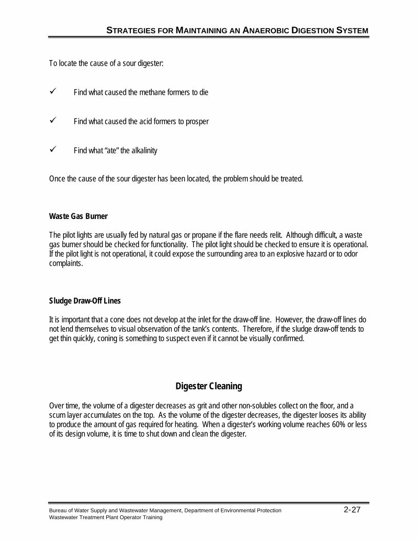
To locate the cause of a sour digester: Find what caused the methane formers to die Find what caused the acid formers to prosper Find what “ate” the alkalinity Once the cause of the sour digester has been located, the problem should be treated. Waste Gas Burner The pilot lights are usually fed by natural gas or propane if the flare needs relit. Although difficult, a waste gas burner should be checked for functionality. The pilot light should be checked to ensure it is operational. If the pilot light is not operational, it could expose the surrounding area to an explosive hazard or to odor complaints. Sludge Draw-Off Lines It is important that a cone does not develop at the inlet for the draw-off line. However, the draw-off lines do not lend themselves to visual observation of the tank’s contents. Therefore, if the sludge draw-off tends to get thin quickly, coning is something to suspect even if it cannot be visually confirmed.
Digester Cleaning Over time, the volume of a digester decreases as grit and other non-solubles collect on the floor, and a scum layer accumulates on the top. As the volume of the digester decreases, the digester looses its ability to produce the amount of gas required for heating. When a digester’s working volume reaches 60% or less of its design volume, it is time to shut down and clean the digester.

STRATEGIES FOR MAINTAINING AN ANAEROBIC DIGESTION SYSTEM
Bureau of Water Supply and Wastewater Management, Department of Environmental Protection 2- Wastewater Treatment Plant Operator Training
28
Pre-Cleaning If the plant has only one digester, or, if it has two digesters in a series, plans must be made to handle the incoming sludge streams while the digester is being cleaned. If the plant has a multiple train of digesters, the incoming sludge can be diverted to working digesters. When deciding whether plant or contract personnel should clean the digester, it is important to consider whether plant personnel have the time and ability to properly clean the digester. Cleaning Methods and Equipment There are a variety of ways to clean a digester. They vary from almost emptying the digester of sludge on a routine basis, to taking the digester off-line, draining it, and flushing out the accumulated deposits. If the unit is taken off-line, the contents flushed out of the digester may require non-routine disposal methods. The scum layer can be mixed into the sludge of solids for disposal. If clean, the deposits from the bottom of the digester can be disposed of with the screenings and grit from the headworks. Safety When cleaning a digester, it is important to follow all confined space entry procedures, including the following guidelines15: When emptying a tank that is practically or completely underground it is important to check the
groundwater level. If the groundwater level is above the based of the tank, the tank may “float” when emptied.
Make sure the gas collection system and sludge system have been isolated and be sure to provide
adequate ventilation through the access holes with the use of explosion-proof vent fans. Sludge lines should never be isolated, by closing the valves on both ends, for several days
because gas production can generate sufficient pressures to cause the line to fail. Test the atmosphere inside the digester for oxygen content, flammable and explosive gases, and
toxic gasses such as hydrogen sulfide. Use explosion-proof motors and electrical equipment. Rope off or barricade the area of the digester to prevent unauthorized personnel from entering the
digester. Lower tools and equipment into the digester, using a bucket or rope or some other means.

STRATEGIES FOR MAINTAINING AN ANAEROBIC DIGESTION SYSTEM
Bureau of Water Supply and Wastewater Management, Department of Environmental Protection 2- Wastewater Treatment Plant Operator Training
29
Cleaning Pipelines and Valves
Pipes may need cleaning if there is a high discharge pressure on the pumps. Frequency of pipe cleaning will be specific to each plant. To clean pipes, the following methods are often utilized: Rodding Pigging (go-devil) Flushing with cleaners or heated solutions Full port valves or plug valves should be used in the piping system. Turns should be made with “crosses” for ease of cleaning. Needle valves, gate valves, and butterfly valves have some of their parts in the flow path which may inhibit certain types of cleaning.
KEY POINTS
Key Points for Unit 2 – Anaerobic Digestion
The breakdown of complex wasted sludge in the absence of oxygen is called anaerobic digestion.
In an anaerobic digester, acid forming bacteria break long chain molecules into simpler
molecules that are acted on by methane forming bacteria.
Methane forming bacteria produce methane gas which can be used as an energy source for heating the digester.
Methane forming bacteria are not as robust as acid forming bacteria and care must be taken
to keep a proper ratio of the two types of bacteria. Fixed cover digesters must have a means of regulating gas pressure in the digester to ensure
proper operation and prevent damage to the cover. Floating cover digesters are often preferred for gas storage. Sludge should not be confined in closed pipe sections for several days because it will
become septic, release gas and possibly rupture pipes. Digester start-up can be done naturally by allowing the existing organisms in the sludge to
grow or it can be “seeded” by adding sludge from another operating digester. Supernatant should be removed on a daily basis. Typical digester gas is approximately 70% methane and 30% carbon dioxide. A sour digester (low pH) can be cured by adding lime, sodium bicarbonate or anhydrous
ammonia. When cleaning a digester, it is very important to follow all pertinent safety procedures
especially confined space entry procedures.
Bureau of Water Supply and Wastewater Management, Department of Environmental Protection 2- Wastewater Treatment Plant Operator Training
30

EXERCISE
Bureau of Water Supply and Wastewater Management, Department of Environmental Protection 2- Wastewater Treatment Plant Operator Training
31
Exercise for Unit 2 – Anaerobic Digestion Multiple Choice – Choose the best answer unless otherwise noted:
1. Anaerobic digestion reduces pathogens by what percentage? a. 50-65% b. 70-84% c. 85-99%
2. Psychrophilic bacteria would be used in which kind of digester? a. Cold digester b. Warm digester c. Hot digester
3. A sour digester occurs when: a. The gas produced by the acid formers gets caught in surfactant b. Acid formers grow faster than methane formers c. Soap and detergent reduce the surface tension of liquids
4. Which V.A./ALK (volatile acids/alkalinity) ratios would create problems in an anaerobic digester?
(Choose all that apply): a. 0.08 b. 0.1 c. 1.0
5. An acidic (low pH) digester can be cured by adding alkalinity to the digester. Which one of the
following compounds is the most cost effective in curing an acidic digester? a. Sodium Bicarbonate b. Anhydrous Ammonia c. Lime (Ca(OH)2) d. Sulphuric Acid
Fill in the blank with a correct response:
6. A material is considered _________________ if water will readily drain from it.
7. An anaerobic digester will produce twelve to eighteen cubic feet of gas for every _____________ of volatile matter destroyed.
8. Normally a digester should be fed often. This can be anywhere from two to ___________ times
per day.
9. Anaerobic digesters produce methane gas and carbon dioxide gas. If the amount of CO2 reaches _____________ % or more, the gas mixture will not be burnable.
10. When a digester’s working volume reaches ________ % or less of its design volume, it is time to
shut down and clean the digester.

REFERENCES
Bureau of Water Supply and Wastewater Management, Department of Environmental Protection 2- Wastewater Treatment Plant Operator Training
32
1 John Brady, William Garber and James F. Stahl, “Chapter 12: Sludge Digestion and Solids
Handling,” in Operation of Wastewater Treatment Plants, Volume II, (Sacramento, CA: California State University, Sacramento Foundation, 2001), p. 149.
2 Brady, p. 150.
3 Brady, p. 154.
4 Brady, p. 151.
5 http://www.sterlingfluidsystems.com/VoidPage23r24.html, (4/24/02).
6 http://www.sterlingfluidsystems.com/VoidPage23r24.html, (4/24/02).
7 Brady, p. 150.
8 Brady, p. 151.
9 Brady, p. 149.
10 Brady, p. 151.
11 Brady, p. 150.
12 Brady, p. 215.
13 Brady, p. 216.
14 Brady, p. 216. 15 Brady, p. 219.

Unit 3 - Aerobic Digestion
Learning Objectives
Identify the main differences between anaerobic and aerobic digestion. Provide an operational overview of the aerobic digestion process. Maintain proper records for an aerobic digester. Identify problems that may occur with an aerobic digester.
Bureau of Water Supply and Wastewater Management, Department of Environmental Protection 3- Wastewater Treatment Plant Operator Training
1
AEROBIC DIGESTION
Bureau of Water Supply and Wastewater Management, Department of Environmental Protection 3- Wastewater Treatment Plant Operator Training
2
Overview
Aerobic digestion uses aerobic microorganisms to decompose organic matter. These organisms live in the presence of oxygen1.
Aerobic digesters cost less to build than anaerobic digesters and are simpler to operate. Therefore, they are often installed at smaller facilities that have a limited staff and budget. In addition, aerobic digesters are used to avoid placing waste aerobic activated sludge with low solids content in an anaerobic digester. If waste aerobic activated sludge is placed in an anaerobic digester, oxygen (dissolved oxygen carryover) will be introduced into the anaerobic atmosphere, and low percent solids sludge will be introduced into the flow stream. Aerobic digesters are used to treat waste activated sludge, waste activated sludge from plants without primary sedimentation tanks, or a combination of waste activated sludge, trickling filter sludge and primary sludge.
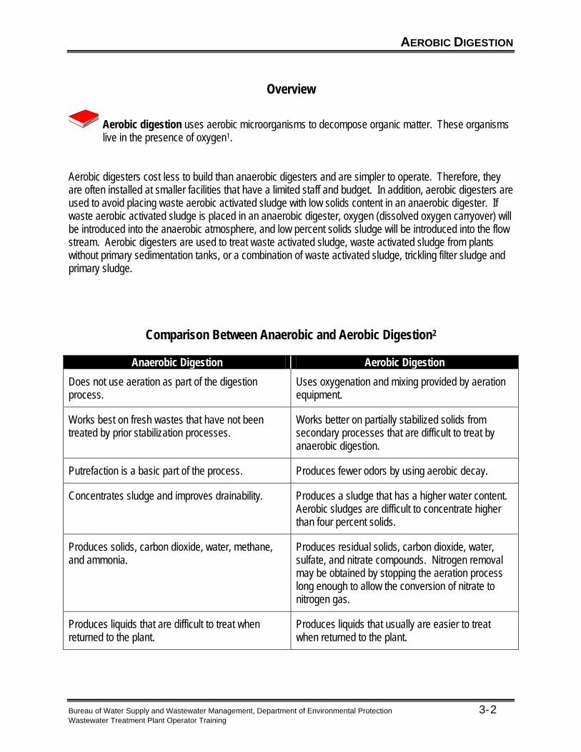
Comparison Between Anaerobic and Aerobic Digestion2
Anaerobic Digestion Aerobic Digestion
Does not use aeration as part of the digestion process.
Uses oxygenation and mixing provided by aeration equipment.
Works best on fresh wastes that have not been treated by prior stabilization processes.
Works better on partially stabilized solids from secondary processes that are difficult to treat by anaerobic digestion.
Putrefaction is a basic part of the process. Produces fewer odors by using aerobic decay.
Concentrates sludge and improves drainability. Produces a sludge that has a higher water content. Aerobic sludges are difficult to concentrate higher than four percent solids.
Produces solids, carbon dioxide, water, methane, and ammonia.
Produces residual solids, carbon dioxide, water, sulfate, and nitrate compounds. Nitrogen removal may be obtained by stopping the aeration process long enough to allow the conversion of nitrate to nitrogen gas.
Produces liquids that are difficult to treat when returned to the plant.
Produces liquids that usually are easier to treat when returned to the plant.

AEROBIC DIGESTION
Bureau of Water Supply and Wastewater Management, Department of Environmental Protection 3- Wastewater Treatment Plant Operator Training
3
Process Description During aerobic digestion, sludge is placed in a large tank and air is forced through the sludge. Unless there is a problem with freezing during the winter months, the tank will probably have an open top. The target of the dissolved oxygen levels is 1 milligram per liter (mg/l); aeration above 1 mg/l increases energy costs without significant benefit. Sludge is usually kept in the tank for at least twenty days, but is dependent on the amount of sludge being generated by the wastewater treatment process. Poor weather conditions may increase that time.
Operation During startup or after the emptying of the tank, fill the first digester to within three feet of the normal
water level and start the aeration process. Use aerobic sludge from the secondary clarifier as seed to start the process.
Continue to pump sludge to the digester as needed until tank contents have reached the normal water level. When adding primary sludge, small amounts should be added at frequent intervals.
Decant the digester by turning off the aeration equipment and allowing the solids to settle and concentrate. Remove enough water to accommodate another 24-hour flow of sludges.
Continue this process each day until the solids level has reached approximately fifty percent of the tank volume after settling.
If using a second tank, begin the same process with the second digester, but transfer a foot of sludge from the first digester to the second.
Once both digesters are in operation, new volume is added to the first tank and mixed flow from the first tank is pumped to the second tank.
Solids from the first tank are pumped to the second tank on a periodic basis, possibly once a week. The goal is to retain the total hydraulic retention time and not have some flow in the digester for a shorter time.
Solids are removed from the third tank for disposal.
Figure 3.1 Photo of an aerobic digester3

AEROBIC DIGESTION
Bureau of Water Supply and Wastewater Management, Department of Environmental Protection 3- Wastewater Treatment Plant Operator Training
4
This process will have a much lower food food-to to-microorganism ratio than what is found in the activated sludge process. During digestion, the organisms are stressed to endogenous respiration instead of using available foods for further cell growth.
During endogenous respiration, organisms use their own cellular makeup as part of the oxidation process4. The organisms use themselves for food when other food sources become scarce. This reduces the amount of material that has to be processed further in the process. It also can account for a reduction in the solids content of the digester.
Aerobic digestion creates a waste that is better for disposal or beneficial use (reduced volume through dewatering, reduced pathogens and a more stabilized product through the reduction of volatile solids).
Records5 Daily records may include: Volume of raw and secondary sludges transferred to the aerobic digesters. Pounds of solids transferred and volatile solids content. Volume of supernatant liquor withdrawn from the digestion tank. Weekly records may include: Supernatant solids and volatile solids content in the digesters. Records kept when the sludge is withdrawn may include: Volume of sludge withdrawn for dewatering. Pounds of solids dewatered and volatile solids content. Pounds of volatile solids destroyed during the digestion process.

AEROBIC DIGESTION
Bureau of Water Supply and Wastewater Management, Department of Environmental Protection 3- Wastewater Treatment Plant Operator Training
5
Problems
Scum problems are usually minimal because the scum is usually collected and disposed of by the time the sludge is placed in the aerobic digester. In addition, the aerobic digester tends to keep the contents mixed well. Odors are usually not a problem when the process is working properly. If odor problems do occur, the following items should be checked: Ensure that proper mixing is occurring in the tank. Ensure that proper dissolved oxygen levels are being maintained. Floating sludge may occur during quiescent settling periods prior to supernatant draw-off. Floating sludge should reincorporate back into the digester’s contents when mixing is resumed. A diffuser may need cleared if dissolved oxygen levels begin to drop or there is a reduction in the amount of mixing occurring in the tank. Diffusers can often be cleared by putting a surge of air into the headers. Aeration equipment such as surface aerators should be monitored for low oil levels and vibration problems. In diffused air systems, the compressor that pushes air into the diffusers is usually maintenance free. As with sludge lines in anaerobic digesters, sludge lines should not be isolated by closing valves on each end for several days because the pressure generated by the production of gas in the line may be sufficient to rupture the line.

KEY POINTS
Key Points for Unit 3 – Aerobic Digestion
Aerobic digesters are often preferred over anaerobic digesters for small systems because they cost less and are simpler to operate.
Aerobic digesters will generally have an open top unless freezing is a problem during the
winter months.
Aerobic digesters generally have fewer odor problems than anaerobic digesters.
Aeration equipment is used to introduce oxygen and mixing action.
During aerobic digestion processes microorganisms use themselves for food, resulting in a reduction of solids content.
Bureau of Water Supply and Wastewater Management, Department of Environmental Protection 3- Wastewater Treatment Plant Operator Training
6

EXERCISE
Bureau of Water Supply and Wastewater Management, Department of Environmental Protection 3- Wastewater Treatment Plant Operator Training
7
Exercise for Unit 3 – Aerobic Digestion
1. The target level of dissolved oxygen in an aerobic digestion tank is:
a. 6 mg/L b. 1 mg/L c. 0 mg/L
2. Sludge is usually kept in the aerobic digestion tank for at least: a. 1 day b. 5 days c. 10 days d. 20 days
3. Aerobic digestion creates a waste that is better for disposal or beneficial use (reduced volume through dewatering, reduced pathogens and a more stabilized product through the reduction of volatile solids). a. True b. False
4. Scum is typically the biggest problem when using aerobic digesters. a. True b. False
5. Odors are not generally a problem with aerobic digesters. If odors occur, what are two remedies that may correct the odor problem? a. ____________________________________________________________________ b. ____________________________________________________________________

REFERENCES
Bureau of Water Supply and Wastewater Management, Department of Environmental Protection 3- Wastewater Treatment Plant Operator Training
8
1 John Brady, William Garber and James F. Stahl, “Chapter 12: Sludge Digestion and Solids
Handling,” in Operation of Wastewater Treatment Plants, Volume II, (Sacramento, CA: California State University, Sacramento Foundation, 2001), p. 149.
2 Brady, p. 221.
3 www.walker-process.com, (4/30/02).
4 Brady, p. 150.
5 Brady, pp. 222 - 223.

Unit 4 – Solids Management Planning
Learning Objectives
Indicate and describe the various methods for processing, dewatering and disposing of sludge. Identify the laws that govern sludge disposal. List specifications, pertaining to solids management, to review during plant design.
Bureau of Water Supply and Wastewater Management, Department of Environmental Protection 4- Wastewater Treatment Plant Operator Training
1

DIGESTED SLUDGE HANDLING
Bureau of Water Supply and Wastewater Management, Department of Environmental Protection 4- Wastewater Treatment Plant Operator Training
2
Overview
Once sludge has been processed through an aerobic or anaerobic digestion system, it must be disposed of. To dewater the sludge for disposal, there are several options available. These include drying beds, reed beds, lagoons, and mechanical dewatering systems. Dewatering may also take place on sludge that has not undergone either aerobic or anaerobic digestion, such as primary sludge from the primary clarifier and secondary sludge from the secondary clarifier. When compared to secondary sludge, primary sludge dewaters more readily and requires less chemical conditioning than secondary sludge. It is important to remember that any water, or filtrate, that is collected from a sludge dewatering process must be sent back through the wastewater treatment process due to the elevated levels of BOD, suspended solids and other contaminants that may impact the environment if discharged directly.
Drying Beds Once solids are digested into a form that has a low pathogen content and is fairly stable, the sludge still has a high water content. One method for removing the water is a drying bed. Drying beds have been used for a number of years and have been proven to be very effective if the proper climate is available. Drying beds can produce a sludge cake that is 75% solids. However, drying beds have several disadvantages. Drying beds are: Labor intensive Land intensive Dependent on climate (can be moderated in some circumstances by enclosing the drying bed)

DIGESTED SLUDGE HANDLING
Bureau of Water Supply and Wastewater Management, Department of Environmental Protection 4- Wastewater Treatment Plant Operator Training
3
Components of a Drying Bed The components of a drying bed are: Underdrain Sand Containment Vehicle treads Distribution methods To apply sludge to a drying bed: 1. Uniformly put the sludge on the drying bed cell. 2. Spread the sludge ten to twelve inches thick. 3. Flush the sludge application line to remove residue. 4. Allow fourteen to twenty days of drying time.
Figure 4.1 Drying Bed

DIGESTED SLUDGE HANDLING
Bureau of Water Supply and Wastewater Management, Department of Environmental Protection 4- Wastewater Treatment Plant Operator Training
4
Reed Beds Reed beds are similar to drying beds, with the exception that reeds are grown in the bed of sludge. The sludge going to a reed bed must be well stabilized. The reeds utilize the moisture and nutrients from the sludge to grow. The root system of the reeds also creates a pathway for oxygen to get into the sludge bed, increasing the decomposition of the sludge by aerobic microorganisms. This accelerated decomposition leads to the decrease in the volume of sludge to be disposed as well as the release of essential plant nutrients, such as nitrogen. Reed beds can have an extended life, sometimes up to 10 years, due to the accelerated decomposition of the sludge and the use of the water and nutrients by the reeds. Once a reed bed is full, the sludge must be removed and disposed or land applied. Once emptied, the reed bed must be re-established with reeds to start the process over again. During its use cycle, the reeds are cut down on a routine basis, typically yearly. The harvested reeds must be disposed of in a landfill or composted.
Lagoon A lagoon is a holding pond for sludge that has no active underdrain system. A lagoon works by evaporation, but has a long drying time because there is no underdrain system. Once a lagoon has been inactive for a while, it can be emptied.
Figure 4.2 Picture of a lagoon1
Mechanical Dewatering Mechanical dewatering is quicker and less space intensive than drying beds, reed beds or lagoons. There are several methods of mechanical dewatering including belt filter presses, plate and frame filter presses and centrifuges.

DIGESTED SLUDGE HANDLING
Bureau of Water Supply and Wastewater Management, Department of Environmental Protection 4- Wastewater Treatment Plant Operator Training
5
A belt filter is compact in size and fairly reliable. With a belt filter there is a continuous feed of
sludge and a continuous discharge of sludge cake and filtrate. Belt filters usually start by allowing the sludge to rest on a porous belt for some draining using gravity prior to being pressed.
Before sludge can be placed in a belt filter, or other dewatering device, it typically requires chemical conditioning, such as the addition of polymer. Polymers act as a bridge that connects solids particles by creating larger particles that trap
additional solids within its mass. Polymers can be added directly to the feed line and mixed in the line using a Venturi-type
restriction in the line or be mixed in a separate mixing chamber. Dosages must be optimized to ensure proper dewatering. Improper dosages can lead to a
sludge cake that is too wet and also to washout, which is characterized by large volumes of water carrying into the dewatering zone and overrunning the sides of the belt.
Factors that are critical to polymer usage include pH and the type of sludge being dewatered (primary, secondary, digested primary and/or secondary or a mixture of any of these types).
Figure 4.3 Diagram of a belt filter2
Figure 4.4 Picture of a belt filter3
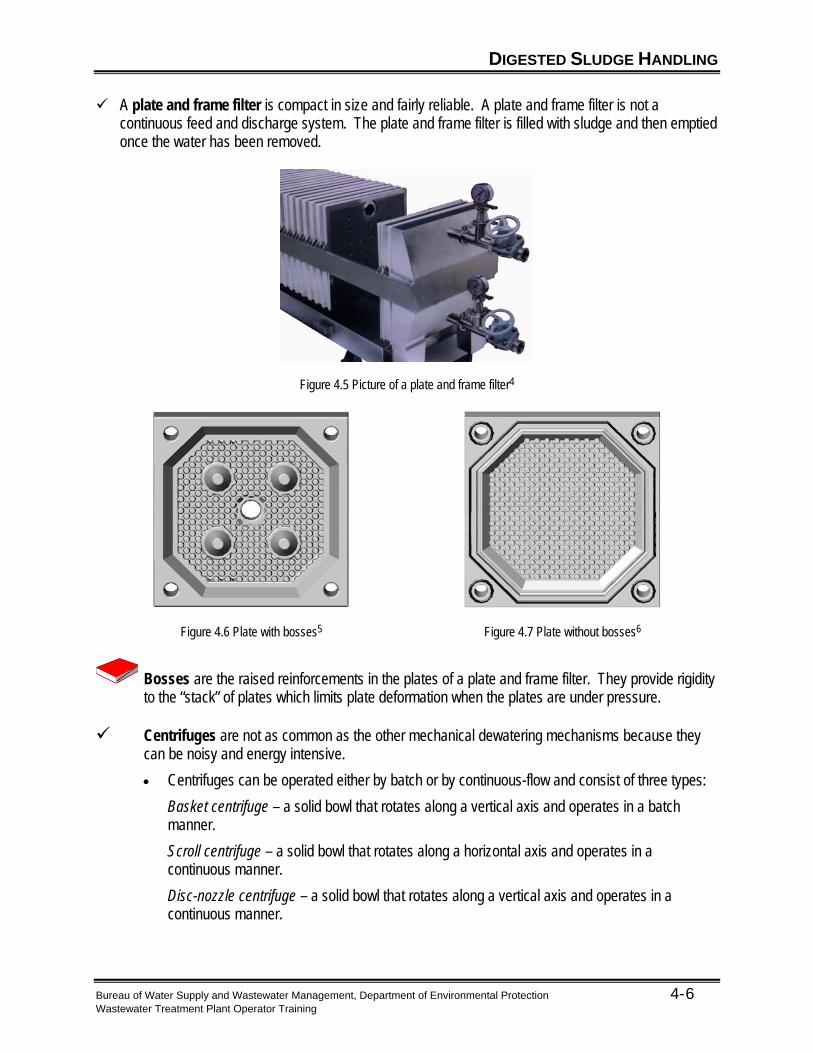
DIGESTED SLUDGE HANDLING
Bureau of Water Supply and Wastewater Management, Department of Environmental Protection 4- Wastewater Treatment Plant Operator Training
6
A plate and frame filter is compact in size and fairly reliable. A plate and frame filter is not a continuous feed and discharge system. The plate and frame filter is filled with sludge and then emptied once the water has been removed.
Figure 4.5 Picture of a plate and frame filter4
Figure 4.6 Plate with bosses5
Figure 4.7 Plate without bosses6
Bosses are the raised reinforcements in the plates of a plate and frame filter. They provide rigidity to the “stack” of plates which limits plate deformation when the plates are under pressure.
Centrifuges are not as common as the other mechanical dewatering mechanisms because they
can be noisy and energy intensive.
Centrifuges can be operated either by batch or by continuous-flow and consist of three types:
Basket centrifuge – a solid bowl that rotates along a vertical axis and operates in a batch manner.
Scroll centrifuge – a solid bowl that rotates along a horizontal axis and operates in a continuous manner.
Disc-nozzle centrifuge – a solid bowl that rotates along a vertical axis and operates in a continuous manner.

SLUDGE DISPOSAL
Bureau of Water Supply and Wastewater Management, Department of Environmental Protection 4- Wastewater Treatment Plant Operator Training
7
Factors that affect the performance of a centrifuge include:
o The type of sludge
o Age of the feed sludge
o Solids and hydraulic loading
o Bowl speed and resulting gravitational forces
o Chemical conditioning.
Methods of Sludge Disposal There are several options for disposing of sludge. Each has certain regulations that must be followed to protect public health and the environment. Methods for disposing of sludge are: Land application involves the application of sludge (biosolids) to agricultural lands or reclamation areas.
Application on agricultural lands or reclamation areas benefits both the sludge generator and the landowner because it provides the sludge generator with a disposal outlet for the sludge, and it provides the landowner with a source of nutrients and soil conditioning, often at no charge.
Distribution and marketing is the direct give away or sale of the sludge to the general public. With this
method of disposal, the sludge generator has little control over the end use of the sludge, therefore, this form of disposal has more restrictions than land application.
Land-disposal involves the disposal of sludge to a landfill. The landfill typical accepts other wastes, as
well as sludge, for disposal. Incineration refers to the burning of sludge until it has been reduced to inorganic ash. Incineration kills
pathogens, and greatly reduces the amount of solids that need to be handled and disposed of. Most regulations on incineration deal with the gasses produced and the visibility of smoke.

SLUDGE DISPOSAL
Bureau of Water Supply and Wastewater Management, Department of Environmental Protection 4- Wastewater Treatment Plant Operator Training
8
Regulations
Environmental Protection Agency (EPA) EPA has regulations that affect the disposal of wastes generated at a wastewater treatment facility. The wastes generated at a wastewater treatment facility will generally fall into one of two categories: Hazardous Waste Non-Hazardous Waste Most sewage sludges are classified as non-hazardous. The regulations for each type of waste will vary depending on the disposal method. In some cases, state regulations may be more restrictive than the regulations imposed by the EPA. Sewage Sludge Use and Disposal Regulation Federal guidelines for sewage sludge can be found in the Federal Register: Title 40: Protection of the Environment Chapter 1: Environmental Protection Agency Part 503: Standards for the Use or Disposal of Sewage Sludge The regulations can be found on-line at http://www.access.gpo.gov/nara/cfr. Select “Search or browse your choice of CFR titles and/or volumes.” Select the most recent “Title 40” link. Select “Part 503.”

SLUDGE DISPOSAL
Bureau of Water Supply and Wastewater Management, Department of Environmental Protection 4- Wastewater Treatment Plant Operator Training
9
Pennsylvania Code The breakdown of the Pennsylvania Code governing sewage sludge is: Commonwealth of Pennsylvania Code Title 25 Chapter 271, in conjunction with Chapters 273, 275,
277, 281, 284 and 285. These chapters can be reviewed at www.pacode.com. Select “Browse,” then select “25 Environmental Protection.”
Rules and procedures for operators of municipal waste management facilities (271.2).
Beneficial Use of Sewage Sludge by Land Application (271, Subchapter J).
Municipal waste landfills (273.1).
General Operating Requirements for the Land Application of Sewage Sludge (275.201).
Operating Requirements for General Composting Facilities (281.201).
Collection, Transportation and Storage of Municipal Waste (285.201).

REVIEW OF PLANS AND SPECIFICATIONS
Bureau of Water Supply and Wastewater Management, Department of Environmental Protection 4- Wastewater Treatment Plant Operator Training
10
Items to Review8
Input by plant operators into plant design may result in a better overall facility design. Listed below are items to review if you are given the opportunity to participate in facility design planning. Review the specifications with regard to design loading rates (peak and average) and check with any plant operational history. Check the following items: Equipment details regarding sizes, capacities, flow rates, pressure, horsepower, and efficiencies. Performance requirements or capabilities. Paints and protective coatings. Instrumentation—remote and local control board items and recorders provided. Equipment warranties and responsibility for acceptance testing. Adequate supply of equipment operation and maintenance manuals. Adequate number of operator and maintenance personnel training hours.

REVIEW OF PLANS AND SPECIFICATIONS
Bureau of Water Supply and Wastewater Management, Department of Environmental Protection 4- Wastewater Treatment Plant Operator Training
11
When examining the plans, emphasize those areas having a direct influence on plant operation and maintenance. For a digestion system, the following items are recommended for review. Examine the general site layout and make sure of adequate access for maintenance equipment
and personnel. If overhead electrical power and telephone lines are involved, note location and make sure of proper clearance for any boom crane.
Note location and sufficiency of power outlets and wash water faucets. Trace the piping flow scheme and examine valve placements and ability to route flow. Examine
operation under automatic and manual modes. Check for adequate access to all valves and piping for maintenance and repairs. Give particular
attention to pipeline cleaning. If pump or other heavy equipment is located in underground galleries, check for provisions for
removal. Check for adequate backup or standby raw sludge pumps. Examine the digester hopper configuration and suitability for cleaning. Note provisions for
adequate ventilation and access during cleaning. Determine how sludge is transferred from the hoppers. Note provisions for line cleaning.
Determine how the raw sludge flow is to be measured. Check if the sludge pump is to be
controlled by timers, sludge density, clarifier blanket level, or some combination thereof. Note how the digester gas is to be measured and check for adequate liquid traps and provisions for
cleaning. Check for location, size, and type of sampling ports.

REVIEW OF PLANS AND SPECIFICATIONS
Bureau of Water Supply and Wastewater Management, Department of Environmental Protection 4- Wastewater Treatment Plant Operator Training
12
Examine the digester heating system. If heat exchangers are used, check for cleaning access.
Note the boiler operation and provision for temperature control. Examine the mixing system. If a propeller mixer is used, note provisions for removing the gear box
or entire unit. Examine the supernatant line and its control. Determine the number of sludge draw-off points. Check for combustible gas analyzers and their location in galleries or closed areas. Carefully study the digester gas system and be sure the sediment and drip traps and flame traps
are properly located and that none are missing.

KEY POINTS
Key Points for Unit 4 – Solids Management Planning
Typically sludge from both aerobic and anaerobic digesters must be dewatered before disposal.
Sludge dewatering methods include drying beds, reed beds, lagoons and mechanical
dewatering systems.
A mechanical dewatering system may require chemical conditioning such as the addition of a polymer to the sludge.
Centrifuges are not often used for dewatering because they are expensive to install and
operate and they are noisy.
Typical options for sludge disposal include land application, distribution and marketing, landfill and incineration.
Sludge disposal methods must meet both EPA and Pennsylvania legal requirements.
Bureau of Water Supply and Wastewater Management, Department of Environmental Protection 4- Wastewater Treatment Plant Operator Training
13

EXERCISE
Bureau of Water Supply and Wastewater Management, Department of Environmental Protection 4- Wastewater Treatment Plant Operator Training
14
Exercise for Unit 4 – Solids Management Planning
1. In a drying bed the typical sludge thickness is ________ to _________ inches.
2. A drying bed requires about __________ days of drying time.
3. Reed beds can last up to ____________ years.
4. Most sewage sludges are classified as: a. hazardous waste b. non-hazardous waste c. radioactive waste d. none of the above
5. Sludge dewatering methods include drying beds, reed beds, lagoons and mechanical dewatering
systems. a. True b. False

REFERENCES
Bureau of Water Supply and Wastewater Management, Department of Environmental Protection 4- Wastewater Treatment Plant Operator Training
15
1 http://waterhome.brc.tamus.edu/texasyst/milkingcenterwaste/sld007.htm, (6/18/02).
2 www.ekotuotanto.fi, (5/15/02).
3 www.ae.iastate.edu/ae573_ast475/slides/belt-filter_press, (5/15/02).
4 http://www.alsopengineering.com/pffilter.htm, (5/15/02).
5 www.afiltration.com, (5/15/02).
6 www.afiltration.com, (5/15/02).
7 John Brady, William Garber and James F. Stahl, “Chapter 12: Sludge Digestion and Solids
Handling,” in Operation of Wastewater Treatment Plants, Volume II, (Sacramento, CA: California State University, Sacramento Foundation, 2001), p. 226. 8 Brady, p. 233 - 234.