
Module 4: Entity Relationship Modeling -...
94
Module 4: Entity Relationship Modeling OBJECTIVES: In this chapter, you will learn: • The main characteristics of entity relationship components • How relationships between entities are defined, refined, and incorporated into the database design process • How ERD components affect database design and implementation • That real-world database design often requires the reconciliation of conflicting goals
Transcript of Module 4: Entity Relationship Modeling -...

Module 4: Entity Relationship Modeling
OBJECTIVES:
In this chapter, you will learn:
• The main characteristics of entity relationshipcomponents
• How relationships between entities are defined,refined, and incorporated into the database designprocess
• How ERD components affect database design andimplementation
• That real-world database design often requires thereconciliation of conflicting goals

The Entity Relationship Model
• The ERM forms the basis of an ERD.
• The ERD represents the conceptual database asviewed by the end user.
• ERDs depict the database’s main components:entities, attributes, and relationships.
• There are various notations used with ERDs—the original Chen notation and the newerCrow’s Foot and UML notations.

• The first two notations are used at the beginningof this chapter to introduce some basic ERmodeling concepts.
• Some conceptual database modeling conceptscan be expressed only using the Chen notation.
• However, because the emphasis is on designand implementation of databases, theCrow’s Foot and UML class diagram notationsare used.

• Because of its implementation emphasis, theCrow’s Foot notation can represent only whatcould be implemented. In other words:
▫ The Chen notation favors conceptual modeling.
▫ The Crow’s Foot notation favors a moreimplementation-oriented approach.
▫ The UML notation can be used for bothconceptual and implementation modeling.

Entities
• Recall that an entity is an object of interest to theend user.
• An entity actually refers to the entity set and not toa single entity occurrence.
• In other words, the word entity in the ERMcorresponds to a table—not to a row—in therelational environment.
• The ERM refers to a table row as an entityinstance or entity occurrence

• In both the Chen and Crow’s Foot notations, anentity is represented by a rectanglecontaining the entity’s name.
• The entity name, a noun, is usually written in all capital letters.
STUDENT
Fig. 4.1 A representation of the STUDENT entity

Attributes• Attributes are characteristics of entities.
• For example,The STUDENT entity may include the attributes:STU_LNAME, STU_FNAME, STU_INITIAL, STU_EMAIL,STU_PHONE.
• In the original Chen notation, attributes are represented byovals and are connected to the entity rectangle with a line.Each oval contains the name of the attribute it represents.
• In the Crow’s Foot notation, the attributes are written in theattribute box below the entity rectangle.
• Because the Chen representation is rather space-consuming,software vendors have adopted the Crow’s Foot attributedisplay.

•
STUDENT
STU_FNAME
STU_LNAME
STU_INITIAL
STU_EMAIL
STU_PHONE
CHEN MODEL
STUDENT
STU_LNAMESTU_FNAMESTU_INITIALSTU_EMAILSTU_PHONE
CROW’S FOOT MODEL
Fig 4.2 The attributes of the STUDENT entity: Chen and Crow’s Foot

Required and Optional Attributes
• A required attribute is an attribute that musthave a value; in other words, it cannot be leftempty.
• In Fig. 4.2, there are two boldfaced attributes inthe Crow’s Foot notation. This indicates that adata entry will be required.
• In this example, STU_LNAME andSTU_FNAME require data entries because of theassumption that all students have a last nameand a first name.

• But students might not have a middle name, and perhaps they do not (yet) have a phone number and an e-mail address.
• Therefore, those attributes are not presented in boldface in the entity box.
• An optional attribute is an attribute thatdoes not require a value; therefore, it can beleft empty.

Domains
• Attributes have a domain.
• A domain is the set of possible values for a givenattribute.
• For example, the domain for the grade point average(GPA) attribute is written (1,5) because the highestpossible GPA value is 1 and the lowest possible valueis 5.
• The domain for the gender attribute consists of onlytwo possibilities: M or F (or some other equivalentcode)

• Attributes may share a domain.
• For instance, a student address and a professoraddress share the same domain of all possibleaddresses.
• In fact, the data dictionary may let a newly declaredattribute inherit the characteristics of an existingattribute if the same attribute name is used.
• For example, the PROFESSOR and STUDENTentities may each have an attribute namedADDRESS and could therefore share a domain.

Identifiers
• The ERM uses identifiers, that is, one or moreattributes that uniquely identify each entity instance.
• In the relational model, such identifiers are mapped toprimary keys (PKs) in tables.
• Identifiers are underlined in the ERD. Key attributesare also underlined in a frequently used table structureshorthand notation using the format:
TABLE NAME (KEY_ATTRIBUTE 1, ATTRIBUTE 2, ATTRIBUTE 3, . . . ATTRIBUTE K)

Fig. 4.3 The CLASS table (entity) components and contents

Composite Identifiers
• Ideally, an entity identifier is composed of only a singleattribute.
• However, it is possible to use a composite identifier, thatis, a primary key composed of more than one attribute.
• For instance, the Tiny College database administrator maydecide to identify each CLASS entity instance (occurrence) byusing a composite primary key composed of the combinationof CRS_CODE and CLASS_SECTION instead of usingCLASS_CODE.
• The combination of CRS_CODE and CLASS_SECTION isa proper candidate key.
• The candidate key (CRS_CODE and CLASS_SECTION) is an acceptable composite primary key.

• If the CLASS_CODE is used as the primary key, the CLASSentity may be represented in shorthand form by:
CLASS (CLASS_CODE, CRS_CODE, CLASS_SECTION, CLASS_TIME, ROOM_CODE, PROF_NUM)
• On the other hand, if CLASS_CODE is deleted, and thecomposite primary key is the combination of CRS_CODEand CLASS_SECTION, the CLASS entity may berepresented by:
CLASS (CRS_CODE, CLASS_SECTION, CLASS_TIME, ROOM_CODE, PROF_NUM)
• Note that both key attributes are underlined in the entitynotation.

Composite and Simple Attributes
• Attributes are classified as simple or composite.
• A composite attribute, not to be confused with a compositekey, is an attribute that can be further subdivided to yieldadditional attributes.
• For example, the attribute ADDRESS can be subdivided intostreet, city, state, and zip code. Similarly, the attributePHONE_NUMBER can be subdivided into area code andexchange number.
• A simple attribute is an attribute that cannot be subdivided.
• For example, age, sex, and marital status would be classified assimple attributes.
• To facilitate detailed queries, it is wise to change compositeattributes into a series of simple attributes.

Single-Valued Attributes
• A single-valued attribute is an attribute that can haveonly a single value.
• For example, a person can have only one Social Securitynumber, and a manufactured part can have only oneserial number.
• Keep in mind that a single-valued attribute is notnecessarily a simple attribute.
• For instance, a part’s serial number, such as SE-08-02-189935, is single-valued, but it is a composite attributebecause it can be subdivided into the region in which thepart was produced (SE), the plant within that region(08), the shift within the plant (02), and the part number(189935).

Multivalued Attributes
• Multivalued attributes are attributes that can have many values.
• For instance, a person may have several college degrees, and ahousehold may have several different phones, each with itsown number.
• Similarly, a car’s color may be subdivided into many colors(that is, colors for the roof, body, and trim).
• In the Chen ERM, the multivalued attributes are shown by adouble line connecting the attribute to the entity.
• The Crow’s Foot notation does not identify multivaluedattributes. The ERD in Figure 4.4 contains all of thecomponents introduced thus far. Note that CAR_VIN is theprimary key, and CAR_COLOR is a multivalued attribute ofthe CAR entity.

•
CAR
MOD_CODE
CAR_VIN
CAR_YEAR
CAR_COLOR
CHEN MODEL
CROW’S FOOT MODEL
Fig. 4.4 A multivalued attribute in an entity

Implementing multivalued attributes
• Although the conceptual model can handle M:Nrelationships and multivalued attributes, youshould not implement them in the RDBMS.
• Remember from Module 3 that in the relationaltable, each column/row intersection represents asingle data value.
• So if multivalued attributes exist, the designermust decide on one of two possible courses ofaction:

1. Within the original entity, create several new attributes, onefor each of the original multivalued attribute’s components.
For example, the CAR entity’s attribute CAR_COLOR can besplit to create the new attributes:
CAR_TOPCOLOR, CAR_BODYCOLOR, and CAR_TRIMCOLOR, which are then assigned to the CAR entity.
▫ Although this solution seems to work, its adoption can lead tomajor structural problems in the table.
▫ For example, if additional color components—such as a logo color—are added for some cars, the table structure must be modified toaccommodate the new color section.
▫ In short, although you have seen solution 1 applied, it is not anacceptable solution.

•
CAR
MOD_CODE
CAR_VIN
CAR_YEAR
CAR_TOPCOLOR
CAR_TOPCOLOR
CAR_TOPCOLOR
CHEN MODEL
CROW’S FOOT MODEL
Fig. 4.5 Splitting the multivalued attribute into new attributes

2. Create a new entity composed of the originalmultivalued attribute’s components.
▫ This new entity allows the designer to define color fordifferent sections of the car.
▫ Then, this new CAR_COLOR entity is related to theoriginal CAR entity in a 1:M relationship.
▫
Table 4.1 Components of the multivalued attribute
SECTION COLOR
Top White
Body Blue
Trim Gold
Interior Blue

• Using the approach illustrated in Table 4.1, youeven get a fringe benefit:
you are now able to assign as many colors asnecessary without having to change the tablestructure.
Fig. 4.6 A new entity set composed of a multivalued attribute’s components

• This is the preferred way to deal withmultivalued attributes.
• Creating a new entity in a 1:M relationship withthe original entity yields several benefits:
It is a more flexible, expandable solution, and itis compatible with the relational model!

Derived Attributes
• Finally, an attribute may be classified as aderived attribute.
• A derived attribute is an attribute whosevalue is calculated (derived) from otherattributes.
• The derived attribute need not be physicallystored within the database; instead, it can bederived by using an algorithm.

• For example, an employee’s age, EMP_AGE, may befound by computing the integer value of thedifference between the current date and theEMP_DOB.
• If you use Microsoft Access, you would use theformula INT((DATE() – EMP_DOB)/365).
• In Microsoft SQL Server, you would use SELECTDATEDIFF(―YEAR‖, EMP_DOB, GETDATE()),where DATEDIFF is a function that computes thedifference between dates. The first parameterindicates the measurement, in this case, years.

• A derived attribute is indicated in the Chen notation by a dashedline connecting the attribute and the entity.
• The Crow’s Foot notation does not have a method for distinguishingthe derived attribute from other attributes.
• Derived attributes are sometimes referred to as computedattributes.
• A derived attribute computation can be as simple as adding twoattribute values located on the same row, or it can be the result ofaggregating the sum of values located on many table rows (from thesame table or from a different table).
• The decision to store derived attributes in database tables dependson the processing requirements and the constraints placed on aparticular application.
• The designer should be able to balance the design in accordancewith such constraints.

•
EMPLOYEE
EMP_LNAME
EMP_NUM
EMP_FNAME EMP_INITIAL
EMP_DOB
EMP_AGE
CHEN MODEL
CROW’S FOOT MODEL
Fig. 4.6 Depiction of a derived attribute

•Table 4.2 Advantages and Disadvantages of Storing Derived Attributes
DERIVED ATTRIBUTE
STORED NOT STORED
Advantage Saves CPU processing cyclesSaves data access timeData value is readily availableCan be used to keep track of historical data
Saves storage spaceComputation always yields current value
Disadvantage Requires constant maintenance to ensure derived value is current, especially if any values used in the calculation change
Uses CPU processing cyclesIncreases data access timeAdds coding complexity to queries

Relationships
• A relationship is an association between entities.
• The entities that participate in a relationship arealso known as participants, and each relationshipis identified by a name that describes therelationship.
• The relationship name is an active or passive verb;
• For example, a STUDENT takes a CLASS, aPROFESSOR teaches a CLASS, a DEPARTMENTemploys a PROFESSOR.

• Relationships between entities always operate inboth directions.
• To define the relationship between the entitiesnamed CUSTOMER and INVOICE, you wouldspecify that:
▫ A CUSTOMER may generate many INVOICEs.▫ Each INVOICE is generated by one CUSTOMER.
• Because you know both directions of therelationship between CUSTOMER and INVOICE, itis easy to see that this relationship can be classifiedas 1:M.

• The relationship classification is difficult to establish if youknow only one side of the relationship.
• For example, if you specify that: ▫ A DIVISION is managed by one EMPLOYEE.
• You don’t know if the relationship is 1:1 or 1:M. Therefore, youshould ask the question ―Can an employee manage more thanone division?‖
• If the answer is yes, the relationship is 1:M, and the secondpart of the relationship is then written as:▫ An EMPLOYEE may manage many DIVISIONs.
• If an employee cannot manage more than one division, therelationship is 1:1, and the second part of the relationship isthen written as:▫ An EMPLOYEE may manage only one DIVISION.

Connectivity and Cardinality
• The term connectivity is used to describe therelationship classification.
• Cardinality expresses the minimum and maximumnumber of entity occurrences associated with oneoccurrence of the related entity.
• In the ERD, cardinality is indicated by placing theappropriate numbers beside the entities, using theformat (x,y).
• The first value represents the minimum number ofassociated entities, while the second value represents themaximum number of associated entities.

Fig. 4.7. Connectivity and Cardinality in ERDs
• Knowing the minimum and maximum number of entity occurrences isvery useful at the application software level.
• For example, Tiny College might want to ensure that a class is nottaught unless it has at least 10 students enrolled.
• Similarly, if the classroom can hold only 30 students, the applicationsoftware should use that cardinality to limit enrollment in the class.

• Cardinalities represent the number of occurrences in therelated entity.
• For example, the cardinality (1,4) written next to the CLASSentity in the ―PROFESSOR teaches CLASS‖ relationshipindicates that each professor teaches up to four classes, whichmeans that the PROFESSOR table’s primary key value occursat least once and no more than four times as foreign keyvalues in the CLASS table.
• If the cardinality had been written as (1,N), there would be noupper limit to the number of classes a professor might teach.
• Similarly, the cardinality (1,1) written next to thePROFESSOR entity indicates that each class is taught by oneand only one professor.
• That is, each CLASS entity occurrence is associated with oneand only one entity occurrence in PROFESSOR.

• Connectivities and cardinalities are established byvery concise statements known as business rules,which were introduced in Chapter 2.
• Such rules, derived from a precise and detaileddescription of an organization’s data environment,also establish the ERM’s entities, attributes,relationships, connectivities, cardinalities, andconstraints.
• Because business rules define the ERM’scomponents, making sure that all appropriatebusiness rules are identified is a very importantpart of a database designer’s job.

• The placement of the cardinalities in the ERdiagram is a matter of convention.
• The Chen notation places the cardinalities on the side of the related entity.
• The Crow’s Foot and UML diagrams place thecardinalities next to the entity to which thecardinalities apply.

Existence Dependence
• An entity is said to be existence-dependent if it can exist inthe database only when it is associated with another relatedentity occurrence.
• In implementation terms, an entity is existence-dependent ifit has a mandatory foreign key—that is, a foreign key attributethat cannot be null.
• For example, if an employee wants to claim one or moredependents for tax-withholding purposes, the relationship―EMPLOYEE claims DEPENDENT‖ would be appropriate.
• In that case, the DEPENDENT entity is clearly existence-dependent on the EMPLOYEE entity because it is impossiblefor the dependent to exist apart from the EMPLOYEE in thedatabase.

• If an entity can exist apart from all of its related entities(it is existence-independent), then that entity isreferred to as a strong entity or regular entity.
• For example, suppose that the XYZ Corporation usesparts to produce its products.
• Furthermore, suppose that some of those parts areproduced in-house and other parts are bought fromvendors.
• In that scenario, it is quite possible for a PART to existindependently from a VENDOR in the relationship―PART is supplied by VENDOR,‖ because at least someof the parts are not supplied by a vendor.
• Therefore, PART is existence-independent fromVENDOR.

Relationship Strength
• The concept of relationship strength is based onhow the primary key of a related entity isdefined.
• To implement a relationship, the primary key ofone entity appears as a foreign key in the relatedentity.

Weak (Non-identifying relationships)
• A weak relationship, also known as a non-identifying relationship, exists if the PK of therelated entity does not contain a PK componentof the parent entity.
• By default, relationships are established byhaving the PK of the parent entity appear as anFK on the related entity.

• For example, suppose that the COURSE and CLASS entitiesare defined as:
COURSE(CRS_CODE, DEPT_CODE, CRS_DESCRIPTION, CRS_CREDIT)
CLASS(CLASS_CODE, CRS_CODE, CLASS_SECTION, CLASS_TIME, ROOM_CODE, PROF_NUM)
• In this case, a weak relationship exists between COURSE andCLASS because the CLASS_CODE is the CLASS entity’s PK,while the CRS_CODE in CLASS is only an FK.
• In this example, the CLASS PK did not inherit the PKcomponent from the COURSE entity.
• Figure 4.8 shows how the Crow’s Foot notation depicts a weakrelationship by placing a dashed relationship line between theentities. The tables shown below the ERD illustrate how sucha relationship is implemented.

Table name: COURSE
Table name: CLASS
Fig. 4.8 A WeakRelationship betweenCOURSE and CLASS

Strong (Identifying) Relationship
• A strong relationship, also known as an identifyingrelationship, exists when the PK of the related entity containsa PK component of the parent entity.
• For example, the definitions of the COURSE and CLASSentities
COURSE(CRS_CODE, DEPT_CODE, CRS_DESCRIPTION, CRS_CREDIT)
CLASS(CRS_CODE, CLASS_SECTION, CLASS_TIME, ROOM_CODE, PROF_NUM)
indicate that a strong relationship exists between COURSEand CLASS, because the CLASS entity’s composite PK iscomposed of CRS_CODE + CLASS_SECTION. (Note that theCRS_CODE in CLASS is also the FK to the COURSE entity.)

Table name: COURSE
Table name: CLASS
Fig. 4.9 A strong (identifying) relationship between COURSE and CLASS

• The Crow’s Foot notation depicts the strong(identifying) relationship with a solid line betweenthe entities, shown in Figure 4.9.
• Whether the relationship between COURSE andCLASS is strong or weak depends on how the CLASSentity’s primary key is defined.
• Keep in mind that the order in which the tablesare created and loaded is very important.
• For example, in the ―COURSE generates CLASS‖relationship, the COURSE table must be createdbefore the CLASS table.
• After all, it would not be acceptable to have theCLASS table’s foreign key reference a COURSE tablethat did not yet exist.
• You must load the data of the ―1‖ side first in a 1:Mrelationship to avoid the possibility of referentialintegrity errors, regardless of whether therelationships are weak or strong.
• Remember that the nature of the relationship isoften determined by the database designer, whomust use professional judgment to determine whichrelationship type and strength best suit the databasetransaction, efficiency, and informationrequirements.

Weak Entities
• In contrast to the strong or regular entity, aweak entity is one that meets two conditions:
1. The entity is existence-dependent; that is, it cannot exist without the entity with which it has a relationship.
2. The entity has a primary key that is partially or totally derived from the parent entity in the relationship.

• For example, a company insurance policy insures anemployee and his/her dependents.
• For the purpose of describing an insurance policy,an EMPLOYEE might or might not have aDEPENDENT, but the DEPENDENT must beassociated with an EMPLOYEE.
• Moreover, the DEPENDENT cannot exist withoutthe EMPLOYEE; that is, a person cannot getinsurance coverage as a dependent unless s(he)happens to be a dependent of an employee.
• DEPENDENT is the weak entity in the relationship―EMPLOYEE has DEPENDENT.‖

EMPLOYEE has DEPENDENT1
(0,N)
M
(1,1)
EMP_NUMEMP_LNAMEEMP_FNAMEEMP_INITIALEMP_DOBEMP_HIREDATE
EMP_NUMDEP_NUMDEP_FNAMEDEP_DOB
CHEN MODEL
CROW FOOT’S MODEL
FIG 4.10 A Weak Entity in an ERD

• Figure 4.11 illustrates the implementation of therelationship between the weak entity(DEPENDENT) and its parent or strongcounterpart (EMPLOYEE).
• Note that DEPENDENT’s primary key iscomposed of two attributes, EMP_NUM andDEP_NUM, and that EMP_NUM was inheritedfrom EMPLOYEE.

Fig. 4.11 A Weak Entity in a Strong Relationship
Table Name: EMPLOYEE
Table Name: DEPENDENT

• Given this scenario, and with the help of thisrelationship, you can determine that:
• Jeanine J. Callifante claims two dependents,Annelise and Jorge.
• Keep in mind that the database designer usuallydetermines whether an entity can be describedas weak based on the business rules.

Relationship Participation• Participation in an entity relationship is either optional or
mandatory.
• Recall that relationships are bidirectional; that is, they operate inboth directions. If COURSE is related to CLASS, then by definition,CLASS is related to COURSE.
• Because of the bidirectional nature of relationships, it is necessaryto determine the connectivity of the relationship from COURSE toCLASS and the connectivity of the relationship from CLASS toCOURSE.
• Similarly, the specific maximum and minimum cardinalities mustbe determined in each direction for the relationship.
• Once again, you must consider the bidirectional nature of therelationship when determining participation.

• Optional participation means that one entity occurrence does notrequire a corresponding entity occurrence in a particular relationship.
• For example, in the ―COURSE generates CLASS‖ relationship, you notedthat at least some courses do not generate a class. In other words, anentity occurrence (row) in the COURSE table does not necessarilyrequire the existence of a corresponding entity occurrence in the CLASStable. (Remember that each entity is implemented as a table.)
• Therefore, the CLASS entity is considered to be optional to the COURSEentity. In Crow’s Foot notation, an optional relationship betweenentities is shown by drawing a small circle (O) on the side of the optionalentity.
• The existence of an optional entity indicates that the minimumcardinality is 0 for the optional entity. (The term optionality is used tolabel any condition in which one or more optional relationships exist.)
• Remember that the burden of establishing the relationship is alwaysplaced on the entity that contains the foreign key. In most cases, thatwill be the entity on the ―many‖ side of the relationship.

• Mandatory participation means that one entityoccurrence requires a corresponding entityoccurrence in a particular relationship.
• If no optionality symbol is depicted with theentity, the entity is assumed to exist in amandatory relationship with the related entity.
• If the mandatory participation is depictedgraphically, it is typically shown as a small hashmark across the relationship line, similar to theCrow’s Foot depiction of a connectivity of 1.
• The existence of a mandatory relationship indicatesthat the minimum cardinality is at least 1 forthe mandatory entity.

CROW’S FOOT SYMBOL CARDINALITY COMMENT
O (0,N) Zero or many. Many side is optional.
| (1,N) One or many. Many side is mandatory.
|| (1,1) One and only one. 1 side is mandatory.
O-| (0,1) Zero or one. 1 side is optional.
Table 4.3 Crow’s Foot Symbols

Crow’s Foot Example
• If you examine the ―PROFESSOR teaches CLASS‖relationship, it is quite possible for a PROFESSOR not toteach a CLASS. Therefore, CLASS is optional toPROFESSOR. On the other hand, a CLASS must be taught bya PROFESSOR. Therefore, PROFESSOR is mandatory toCLASS.
• Note that the ERD model in shows the cardinality next toCLASS to be (0,3), thus indicating that a professor may teachno classes at all or as many as three classes. And each CLASStable row will reference one and only one PROFESSOR row—assuming each class is taught by one and only one professor—represented by the (1,1) cardinality next to the PROFESSORtable.

• Failure to understand the distinction betweenmandatory and optional participation inrelationships might yield designs in whichawkward (and unnecessary) temporary rows(entity instances) must be created just toaccommodate the creation of required entities.
• Therefore, it is important that you clearlyunderstand the concepts of mandatory andoptional participation.

Relationship Degree
• A relationship degree indicates the number of entitiesor participants associated with a relationship.
• A unary relationship exists when an association ismaintained within a single entity.
• A binary relationship exists when two entities areassociated.
• A ternary relationship exists when three entities areassociated.
• Although higher degrees exist, they are rare and are notspecifically named.

Fig. 4.12 Three Types of Relationship Degree

Recursive Relationship
• A recursive relationship is one in which arelationship can exist between occurrences ofthe same entity set. (Naturally, such a conditionis found within a unary relationship.)
Fig.4.13 ER Representation of Recursive Relationships

Developing an ER Diagram• The process of database design is an iterative rather than a linear
or sequential process. The verb iterate means ―to do again orrepeatedly.‖
• An iterative process is, thus, one based on repetition ofprocesses and procedures.
• Building an ERD usually involves the following activities:1. Create a detailed narrative of the organization’s description of
operations.2. Identify the business rules based on the description of operations.3. Identify the main entities and relationships from the business rules4. Develop the initial ERD.5. Identify the attributes and primary keys that adequately describe
the entities.6. Revise and review the ERD.

• During the review process, it is likely that additionalobjects, attributes, and relationships will beuncovered.
• Therefore, the basic ERM will be modified toincorporate the newly discovered ER components.
• Subsequently, another round of reviews might yieldadditional components or clarification of theexisting diagram.
• The process is repeated until the end users anddesigners agree that the ERD is a fair representationof the organization’s activities and functions.

• During the design process, the database designerdoes not depend simply on interviews to helpdefine entities, attributes, and relationships.
• A surprising amount of information can begathered by examining the business forms andreports that an organization uses in its dailyoperations.
• To illustrate the use of the iterative process thatultimately yields a workable ERD, let’s start withan initial interview with the Tiny Collegeadministrators. The interview process yields thefollowing business rules:

1. Tiny College (TC) is divided into severalschools: a school of business, a school of artsand sciences, a school of education, and aschool of applied sciences. Each school isadministered by a dean who is a professor.Each professor can be the dean of only oneschool, and a professor is not required to bethe dean of any school.
Therefore, a 1:1 relationship exists betweenPROFESSOR and SCHOOL. Note that thecardinality can be expressed by writing (1,1)next to the entity PROFESSOR and (0,1) nextto the entity SCHOOL.

2. Each school comprises several departments.
For example, the school of business has anaccounting department, a management/marketingdepartment, an economics/finance department, anda computer information systems department.
Note again the cardinality rules: The smallestnumber of departments operated by a school is one,and the largest number of departments isindeterminate (N). On the other hand, eachdepartment belongs to only a single school;
Thus, the cardinality is expressed by (1,1). That is,the minimum number of schools that a departmentbelongs to is one, as is the maximum number.

First segment of Tiny College ERD

3. Each department may offer courses.
For example, the management/marketingdepartment offers courses such as Introduction toManagement, Principles of Marketing, andProduction Management.
Note that this relationship is based on the way TinyCollege operates.
If, for example, Tiny College had some departmentsthat were classified as ―research only,‖ thosedepartments would not offer courses; therefore, theCOURSE entity would be optional to theDEPARTMENT entity.

Second segment of Tiny College ERD

4. A CLASS is a section of a COURSE. That is, adepartment may offer several sections (classes)of the same database course. Each of thoseclasses is taught by a professor at a given time ina given place.
In short, a 1:M relationship exists betweenCOURSE and CLASS. However, because acourse may exist in Tiny College’s course catalogeven when it is not offered as a class in a currentclass schedule, CLASS is optional to COURSE.

Third segment of Tiny College ERD

5. Each department should have one or moreprofessors assigned to it. One and only one ofthose professors chairs the department, and noprofessor is required to accept the chair position.
Therefore, DEPARTMENT is optional toPROFESSOR in the ―chairs‖ relationship.
Fourth segmentof Tiny College ERD

6. Each professor may teach up to four classes;each class is a section of a course. A professormay also be on a research contract and teach noclasses at all.
Fifth segment of Tiny College ERD

7. A student may enroll in several classes but takes each class only onceduring any given enrollment period.
For example, during the current enrollment period, a student may decideto take five classes—Statistics, Accounting, English, Database, andHistory—but that student would not be enrolled in the same Statisticsclass five times during the enrollment period!
Each student may enroll in up to six classes, and each class may have upto 35 students, thus creating an M:N relationship between STUDENTand CLASS. Because a CLASS can initially exist (at the start of theenrollment period) even though no students have enrolled in it,STUDENT is optional to CLASS in the M:N relationship. This M:Nrelationship must be divided into two 1:M relationships through the useof the ENROLL entity, but note that the optional symbol is shown next toENROLL. If a class exists but has no students enrolled in it, that classdoesn’t occur in the ENROLL table. Note also that the ENROLL entity isweak: it is existence-dependent, and its (composite) PK is composed ofthe PKs of the STUDENT and CLASS entities. You can add thecardinalities (0,6) and (0,35) next to the ENROLL entity to reflect thebusiness rule constraints

Sixth segment of Tiny College ERD

8. Each department has several (or many) studentswhose major is offered by that department.However, each student has only a single major andis, therefore, associated with a single department.
However, in the Tiny College environment, it ispossible—at least for a while—for a student not todeclare a major field of study. Such a student wouldnot be associated with a department; therefore,DEPARTMENT is optional to STUDENT. It is worthrepeating that the relationships between entities andthe entities themselves reflect the organization’soperating environment. That is, the business rulesdefine the ERD components.

Seventh segment of Tiny College ERD

9. Each student has an advisor in his or herdepartment; each advisor counsels severalstudents. An advisor is also a professor, but notall professors advise students. Therefore,STUDENT is optional to PROFESSOR in the―PROFESSOR advises STUDENT‖ relationship.
Eight segment of the Tiny College ERD

10. The CLASS entity contains a ROOM_CODEattribute. Given the naming conventions, it isclear that ROOM_CODE is an FK to anotherentity. Clearly, because a class is taught in aroom, it is reasonable to assume that theROOM_CODE in CLASS is the FK to an entitynamed ROOM. In turn, each room is located in abuilding. So the last Tiny College ERD is createdby observing that a BUILDING can containmany ROOMs, but each ROOM is found in asingle BUILDING. In this ERD segment, it isclear that some buildings do not contain (class)rooms. For example, a storage building mightnot contain any named rooms at all.

Ninth segment of Tiny College ERD

• Using the preceding summary, you can identify the following entities:
SCHOOL COURSEDEPARTMENT CLASSPROFESSOR STUDENTBUILDING ROOMENROLL (the associative entity between STUDENT and CLASS)
• Once you have discovered the relevant entities, you can definethe initial set of relationships among them. Next, you describethe entity attributes. Identifying the attributes of the entitieshelps you to better understand the relationships amongentities.
• Table 4.4 summarizes the ERM’s components, and names theentities and their relations.
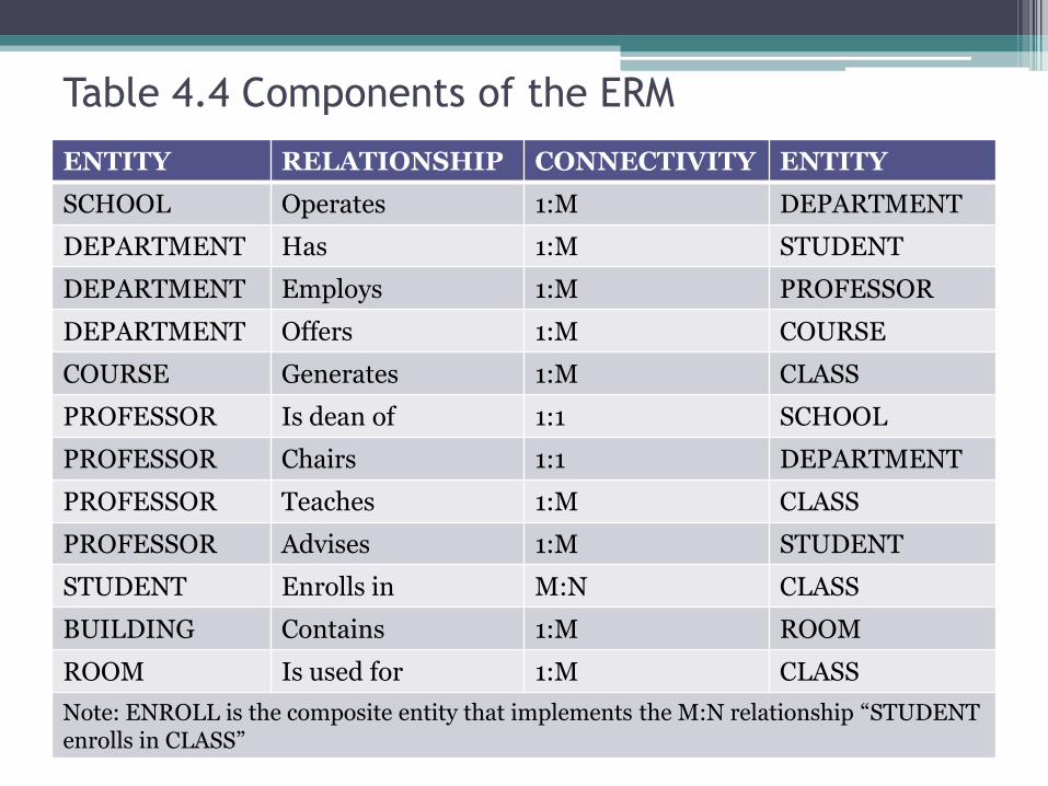
Table 4.4 Components of the ERM
ENTITY RELATIONSHIP CONNECTIVITY ENTITY
SCHOOL Operates 1:M DEPARTMENT
DEPARTMENT Has 1:M STUDENT
DEPARTMENT Employs 1:M PROFESSOR
DEPARTMENT Offers 1:M COURSE
COURSE Generates 1:M CLASS
PROFESSOR Is dean of 1:1 SCHOOL
PROFESSOR Chairs 1:1 DEPARTMENT
PROFESSOR Teaches 1:M CLASS
PROFESSOR Advises 1:M STUDENT
STUDENT Enrolls in M:N CLASS
BUILDING Contains 1:M ROOM
ROOM Is used for 1:M CLASS
Note: ENROLL is the composite entity that implements the M:N relationship ―STUDENT enrolls in CLASS‖

• You must also define the connectivity andcardinality for the just-discovered relationsbased on the business rules.
• However, to avoid crowding the diagram, thecardinalities are not shown. Figure 4.35 showsthe Crow’s Foot ERD for Tiny College.
• Note that this is an implementation-readymodel. Therefore it shows the ENROLLcomposite entity.

The completed ERD for Tiny College

Conceptual UML Class diagram for Tiny College

Database Design Challenges:
Conflicting Goals
• Database designers often must make designcompromises that are triggered by conflicting goals,such as adherence to design standards (designelegance), processing speed, and informationrequirements.
Design standards. The database design mustconform to design standards. Such standards haveguided you in developing logical structures thatminimize data redundancies, thereby minimizingthe likelihood that destructive data anomalies willoccur.

• Processing speed. In many organizations,particularly those generating large numbers oftransactions, high processing speeds are often a toppriority in database design. High processing speedmeans minimal access time, which may be achievedby minimizing the number and complexity oflogically desirable relationships.
• Information requirements. The quest for timelyinformation might be the focus of database design.Complex information requirements may dictate datatransformations, and they may expand the numberof entities and attributes within the design.Therefore, the database may have to sacrifice someof its ―clean‖ design structures and/or some of itshigh transaction speed to ensure maximuminformation generation.

Module 4: Summary
• The ERM uses ERDs to represent the conceptualdatabase as viewed by the end user.
• The ERM’s main components are entities,relationships, and attributes.
• The ERD also includes connectivity and cardinalitynotations.
• An ERD can also show relationship strength,relationship participation (optional or mandatory),and degree of relationship (unary, binary, ternary,etc.).

• Connectivity describes the relationship classification (1:1,1:M, or M:N).
• Cardinality expresses the specific number of entityoccurrences associated with an occurrence of a relatedentity.
• Connectivities and cardinalities are usually based onbusiness rules.
• In the ERM, an M:N relationship is valid at theconceptual level.
• However, when implementing the ERM in a relationaldatabase, the M:N relationship must be mapped to a setof 1:M relationships through a composite entity.

• ERDs may be based on many different ERMs.However, regardless of which model is selected, themodeling logic remains the same. Because no ERMcan accurately portray all real-world data and actionconstraints, application software must be used toaugment the implementation of at least some of thebusiness rules.
• Unified Modeling Language (UML) class diagramsare used to represent the static data structures in adata model. The symbols used in the UML class andER diagrams are very similar. The UML classdiagrams can be used to depict data models at theconceptual or implementation abstraction levels.

• Database designers, no matter how well they are able to produce designsthat conform to all applicable modeling conventions, are often forced tomake design compromises.
• Those compromises are required when end users have vital transaction-speed and/or information requirements that prevent the use of ―perfect‖modeling logic and adherence to all modeling conventions.
• Therefore, database designers must use their professional judgment todetermine how and to what extent the modeling conventions are subjectto modification.
• To ensure that their professional judgments are sound, databasedesigners must have detailed and in-depth knowledge of data-modelingconventions.
• It is also important to document the design process from beginning toend, which helps keep the design process on track and allows for easymodifications down the road.


