MODULATION AND DETECT LON OF OPTICAL SIGNALS … · f}rs-/&330 MODULATION AND DETECT LON OF OPTICAL...
25
f} rs - /&330 MODULATION AND DETECT LON OF OPTICAL SIGNALS F. E. Goodwin Notes for lecture XI, Course X449, Detection of Infrared Radiqtton Heterodyning in the IR llrAugust 1972 ! ! Q --- --------- . (NASA-CR-129181) MODULATION AND DETECTION N73-11460 !OF OPTICAL SIGNALS F.E. Goodwin (Hughes Research Labs.) 11 Aug. 1972 25 p CSCL 20E Unclas G3/16 16330- Reproduced ,bY NATiONAL TECHNiCAL INFORMATION SERVICE us Department of Commerce " VA. . https://ntrs.nasa.gov/search.jsp?R=19730002733 2018-07-07T21:18:10+00:00Z
Transcript of MODULATION AND DETECT LON OF OPTICAL SIGNALS … · f}rs-/&330 MODULATION AND DETECT LON OF OPTICAL...

f} rs - /&330
MODULATION AND DETECT LON OF OPTICAL SIGNALS
F. E. Goodwin
Notes for lecture XI, Course X449, Detection of Infrared RadiqttonHeterodyning in the IR
llrAugust 1972
!
!
Q
--- --------- -~---------------------
. (NASA-CR-129181) MODULATION AND DETECTION N73-11460!OF OPTICAL SIGNALS F.E. Goodwin (HughesResearch Labs.) 11 Aug. 1972 25 p CSCL
20E UnclasG3/16 16330-
Reproduced ,bY
NATiONAL TECHNiCALINFORMATION SERVICE
us Department of Commerce" Spri~gfi.ld: VA. ~2151 .
https://ntrs.nasa.gov/search.jsp?R=19730002733 2018-07-07T21:18:10+00:00Z

j
OUTLINE
I INTRODUCTION,I
iII MODULAT~ON OF OPTICAL CARRIERS
! .1. Intensity Modulation
I2. Subcarrier Modulation3. pdlarization Modulation
/4. I~tracavity Frequency Modulation
,5. Ihtracavity Coupling Modulation6. p/u 1se Mo du1a t ion
IIII DIRECt DETECTION AND DEMODULATION
.1. Direct Detection of Carriers1.1 Noise-Equivalent-Power (NEP}T' Thermal
Limited1.2 Noise-Equivalent-Power (NEP}B' Background
Limited1.3 Hoise-Equi~alent-Power (NEP}S' Signal Shdt
Noise Limited. I .
1.4 Signal-to-~oise Ratio. of Unmodulated Carriers(S/N}dc· ·1
2. Demodulation and \Information Signal-to-Noise {S/N}m
IV COHERENT DETECTION AND DEMODULATION1. Physical and Geometrical Considerations2. Required Local Oscillator Power3. Heterodyne Conversion Gain4. Demodulation
V COMPARISON OF TWO COMMUNICATION SYSTEM CONCEPTS

I
II
I. INTRODUCTION
This 'paper. provides a summary of information relatedto the modulation and' detection of information'on opticalcarriers. It is not intended to be a thorough investigationof either modulation or detection, but rather to supplementother more detailed works by emphasizing the treatment ofinformation transfer through an entire system. The summarylooks at the most common configurations; intensity modulation,amplitude modulation, frequency ~r phase modulation, and bothdirect and coherent detection. In assessing these configurations informa~ion capacity and message signal-to-noise 'ratioare used as a basis of comparison.
The physical and geometric treatment of optical heterodyne (or coherent) detection is given in some detail, sincet his i s the pr inc i pa 1 to Pi' c for the 1ec t ur e . The adva ntag esof coherent detection in the i'nfrared are evident because thelack of intrinsic gain in infrared photodetectors makes thermalnoise insurmountable. Now that coherent detection techniquesare available, an enormous improvement in detector sensitivityis possible. To illustrate this point, two communicationsystem concepts are compared, one using direct detection anda photomultiplier detector at 1.06 ~m, and the other usingcoherent detectio~ with an infrared photodiode at10.6 ~m.
, '
/i
,/J Ii
II

DC termfundamental2nd harmonic3rd harmonicetc.
II MODULATION OF OPTICAL CARRIERS
Modulation of an opti~al carrier differs from modulationof a radio freq'uencycarri.er l\primaril Y because of the characteristics and limitations of the devices u~ed for performing theoptical modulation. At optic~l frequencies many modulators aredeiigned to operate directly ~pon the c~rrier intensity (amplitude squared of ·the electric field) rather than the amplitude
I .of .the carrier as is common with radio frequency modulator·s.1tis con ve ni en t t hat i n dire c t (q uant um) de t ec t ion 0 fan _'optical signal, the amplitude of the detector current is proportional to the carrier intensity. For this reason, amplitudemodulation of the carrier is of little interest in direct detectionschemes. Further, its production is achievable only for extremelysmall·indices and is useful only for special purposes. However,phase modulation, frequency modulation and polarizati.on modulationare eas i 1y achi evedin the· 0 ptic a.l s pect rum .
oJ
Electro-optic modulators obey the relation
pet) = posin 2r(t)sin 2wctwhere ret) is the retardation introduced by the modulating
voltage = r + rsinW t. 0 m m
Wc is the optical carrier frequencyPo is the peak power df the laser carrier before enteringthe modulator.
In order to be able to analyze th.is modulation by' conventionalmeans, we begin by expanding the modulating term
51 i n2 r (t) :: ~ [ 1 - co s (2 r0) 1: (?T'~) ]
'\"'
'.+ sin 2 f o J 1 (2r in )sinw mt~ cos 2 f J'2 ( 2f· ) cos 2w t
. 0 m m, + sin 2· f 0 J 3 ( 2f m)sin 3w mt
The electro-opticreta~dation
is adjusted such t~at 'with nomitted through the .modulato~.
then be arproximated by
~. [r + f m sin wmt]!.i
II
jI
contains the bias term f whichomodulation, half the power is trans-
The m~dulating term sin 2r(t) can
I,/ ,.
I I·i tI ,(I ,"
II

1.
'/"
Intensity MOjUlation;:
In optical ~ystems wnere an electro-optic modulator isI
used extern~l to the laser/source t~e output may be either inthe form of loss modulation at a fixed' polarization or it maybe polarization modulated. The basic ,form for loss (intensity)modulation is
where Po is the power of the laser carrier before enteririgthe modulator
Po/2 is the average laser carrier power out of themodul~tor (biased power without modulation)
m is the modulation index defined as 1.0 for 100%modulation*
M(t) is the message function, balanced, having maximumvalues of ± 1.0. Example: M(t) = cos w t where wm mis the modulating frequency.
I
( 1)
It is convenient to examine the exponential form of the modu-lation in order to examine the various sidebands and their relative intensities. Assuming M(t) is a periodic sinusoidal function,'
[Il iwmt -iwmt] 2
pet) = Po/2 1 +;m/2(e + e ) sin wet.
I ~
-c..I
* Note: m is related to the electro-optic peak retardation rm
m ~ 2 sin (2ro)Jl(2rm)~ rm r;/2 + r;/12'- .....I
!.' ....

INote that ~ thq power is in the optical carrier and ~ is inthe message fu~ction.
II
2. sUbca'rdi er Modul at ionIn subdarrier modulation thfr basic urimodulated carrier
I
appears as a ~ingle tone wI intensity modu19tion.i I
P = Pol 2 [1 + m1cos w1t ] sin 2OJ ct.
However, the message function is not contained in the aboveexpression. Instead, the message function is multiplied with
I .
the carrier to form the expre~sion
\ 2P = Po/2 [1 + ~(1 + m2 \cos w2t) mi cos wIt] sin wct (2)
where how m2 is the mOdulatio~ index of the message function onthe subcarrier and m1 is the modulation index of the subcarrieron the optical carrier. Assuming a sinusoidal M(t} = cos w2t,then equation (2) yields the spectrum.
Po~
M Po -iw,t~e 'I,
III
o w,- kla. fII, W, + 101,
described as modulation ofTwo receivers channels which

Channel 2
Channel 1
I ;'/are polarization senSi~ve are iJen located' at orthogonal
polari zations such thaI' half o{,the power enters each channel.
The mod u1a t i.0 n fun ct i ojn i s def i ~ ed by
PI - P/2 [ 1 + mM (t l ] f ~ 2 wet
P2= Po/2 [ 1/) mM(tlVs',in2
wet
'. I
P1,and P2
may 'be right and (left hand circular polarization ororthogonal linear polarizations. In the detection process,Chan ne1 2 wi 11 be sub t r a'd::ed fro m Chan nell ..
The spectrum of the modulation is then identified foreach channel as follow~:
~ .
. (3)
Channel 1
o
Channel 2 o---------..I~,__----,r_-----.L-----------~w
;.:·f,
-~-02.
It willmessagemission
be noticed that theterms add such thatof information.
,.
carrier term ~ancels out and thea 11 the power is use.d in the tr-ans-
o

i
/I
I
f
I
4. Intracavity Frequency'Modulation (Optical FM)/
Looking at the classical expression for frequency modu-
lated s{gnal," the field is expressed as
E(t) = E~cos(wt + Bsinwmt).
The spe~trum tJrms of this signal for large deviation is given"by
the well 'known! Be:se] Function of the f'irst kind i
E(tl, =h~ In(~)c:S(Wc,+ nwmlt:
Of practical ~onsideration is the fact that the average power in
a phase or fJequcncy modulated wave is constant; the sum of the
squares of the individual Fourier components of the modulated wave
is equal to unity.
,When intracavity opti~al frequency modulation is used,
there are two constraints wh1ch affect the resulting modulation
spectrum. First, the modula~ion index is a function of cavity param
eters and the peak retardation, but is usually a value less than
unity. The low value of FM modulation index differs from the
usual rf case where very high values are used. This results in
most of the modulate"d,"energy being limited to tHe first order
sideba n'd s .
Second, optical frequency modulation ii detected with optical
heterodyne detection w~pre a conventional i,.f. amplifier is used.
The 0 ptim i za t i on 0 f the des i gn 0 f the sys t em call s . for ani. f .
bandwidth which accommodates only the first order sidebands.
Under thes! circumstances, it is con~enient to have an explicit
(If )
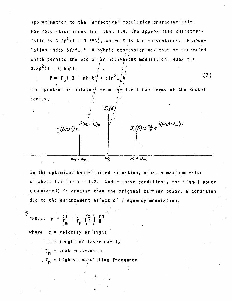
approxi~atipn to the "effective" modulation characteristic.
For modulation index-less th~n 1.4, the approximate character
istic is 3.213 2 (1 - O.55I3)"where 13 i,s the conventional FM modu
lation index of/fm.* A h!brid expression may thus be generated- I I '
which-permits the use n equivJl~nt modulation. index m =2 I ,I
3.213 (l - 0.5513). - 11p z. Po ( 1 + mM(t) ) sin 2w ,
The spectrum is olYtaine! from ujel first two terms of the Bessel
Series,
In the optimized band-limited situation, m has a maximum value
of about 1.5 for 13 ~ 1~2. Under these conditions, the signal power
(modulated) is greater than the original carrier power, a condition
due to the enhancement effect of frequencY modulation.
*NOTE: a = off m = im. (IT) rm
IT
where c = vel oci tyof .', i ght
L = length of laser, cavity
r~ = peak retardation
f =m highest modulating frequencyt
...

rI
/ 5 . Intracavity Coupling Modulationi ,
COupling modulation is of great interest for infrared.lasers because· of the e~hanced modulation effect and the nearly
unlimited bandwfdth c~pabilities of the technique. The basicI
modulation equa;tion is similar to that for simp1e.intensity
modulation.
p = P sln 2r(t}
h P · Cthl . 1 t' , th 1 't thwere c 1S ~ C1rcu a 1ng power 1n e aser caV1 y ra er
than the exte1nal, output power of the laser. The enhancement
offered by th~ technique is thus equal to the ratio of the cir-I
Cu1at; 'n ~ pow e .r tot he 0 ptima11 y co uP1ed 0 ut put power 0 f the 1a se r .
For the; carbon dioxide laser at 10.6 \.1m, this ratio is about 10 to l.
The coupling parameter P/Pc' or mM(t), can be expanded as
follows:
mM (t) = P/ Pc
= ~ [1= sin 2r(t)
cos 2r(i)]
Let f(t) = f o + fmsinwtm.mM(t) = ~ [1 - cos (2~) Jo U)Tm)] , ..
+ sin(2fo )J 1(2f m')sinwmt
( cos (2f o }J 2}2fm)COS 2wmt
+ sin(2fo}J 3( 2fffi)sin 3wmt
DC term
fundamental
2nd harmonic
3rd harmonic
etc.
The averag~ power coupled from the laser is proportional to the
first·te~.Jor dc term wh·.ich is dependent both upon f o ' the de
retardat~fn and f m, the peak ac retardation. The first term may
be set to~ero which leaves only the even harmonics. This type.'C:J

of mod'ulation is equivalent to double sideband-suppressed-I
carrier DSBSC modulation. 'Injectio~ of a carrier at thereceiver restores the fundamental and odd harmonics. Thespectral terms which con~ain information are
mM ( t) = +J l' (2 r m)lSi nWmt ,:,
-J 2(2rm)!cos 2wm~ f J 3(2rm) cos 3wmt
· (rm - r~3 + r:,!, ... ) sinwmt - •••.
mM(t),,=Pm,P c ·.)l(2rm) ~iin wmt.
Thus, the mod u1ate d sid eban d plowe r i s
Pm~ PcmM(t) j,rin2wct.1 ,·nje.dul
,) , t.o.rt';'~
_wW\
P -i rJ...lt"I\ ~e
6. Pulse Modulation ~
(5')
Pulse modulation is important for both radar applicationsand communications where binary information is transmitted in theform of pulse "1" and no-pulse "0". In this form of modulationmodulated signal power has no meaning. Since every pulse containsinformation, there is no energy lost in carriers. The criteriafor effective transmission of information over a system of thissort is the probability of ~etection at the receiver. The spectrum
,of a single pulse is important only in re~ation to the informationrate, since pulse overlap will result in a reduction in the probability of detection. The parameter of optical energy per pulse hasmore significance than optical power. Thus, the primary factor inpulse modulation is the single puls~ energy Es :
,'-

1.
III
be composed of a signalIn such a case, the total
!
I !
I !
DIRECT AND OEMJO(LATION
Dire ctOe t ec t i o! 0 f Car r/; ~ r sI I
Direct detection is defined as the ~irectuse of electronsI
pro due ed by ion i zat ion s .0 f ph olt 0 nsin c ide nton the de tee tor. Forexample, assume Jan ooltical. fl~x of7· l~ If/;::: ~Te'l, t<•
. .
where P is the optical power and hv is the energy per photon.A signa'l current is produc,ed in the detector of
. G Pst s -= r; e hv
)
where, II is the number of ionizations per photon (quantum efficiency)G is the number of electrons per ionization (gain)e is the electronic chargef eff is the'effective temperature of the load resistance
. RL is the load resistance.
The gain of a photomultiplier may be 10 5 or higher, where a singlephoton can generate thousands of electrons and where individualphoton events are easily detected. An avalanche photodiode mayhave a gain of 10 2 or more. !However, most infrared photodiodes.do not have intrinsic gain.
The optical power ~ above may~power Ps and a background power Pb"cur r ent i.1s
The power in .. the resistor is given by'12.G Le 2.(~ -t- ~).l. Ie..
c' 2Rt. :::(h y)2>
The noise power (shot) in the resistor is the shot noise producedby the direct current in the detector.
:,~

F is the noise factor defined by the increase in noise introduced by the current Jain process. The value of F varies fordifferent types of detectors.
F = 1 for photodiodes\
F - 1. 3 for p hot 0 mu1tip 1 i e rs .F =2 for photo conductorsF > 2 for avalanche photodiodes.
The load resistor also has thermal noise so that the total noisepower in the load resistor is
Pn =~(Ge) i BRF + 4kTB.de.
Now ~c.in the above "equation is the total dc current in the circuitand is the sum of that produced by the signal flux, the backgroundflux, and dark current. In this discussion, we are assumingthe dark current to be negligible and that the main shot currentis produced by the signal and the background flux
i dc = t1G e. (Psh:Pb ) .
The noise power in the load resistor becomes
= ~ r; (G e )").(~ + PIJ) i3 R F + '-i k ""8 .Pn hv.f
1.1 Noise-Equivalent-Power (NEP)T' Thermal Limited
The thermal limited case is that usually encountered withinfrared photodiodesand photoconductors used in direct detectionprocesses. Here th~ signal!cur~ent generated by the optical signalflux must be greater than the "equivalent thermal current" in thecircuit. The thermal noi~~ current/it in the load resistor isdefined in the relation I .!;
iiR '='·4ktB. I' ;,!I I
The thermal current is a noise c~ryrent and not a dc c~rrent. Wenow ask the question what equivafent optical noise flux ~t willproduce the same amount/Of nois1.current, it = tlGe~t. Again,the optical noise f1Ux/~s a nOite modulated flux as opposed to adc flux. Substituting/this ex~ression for it in the thermal noiseequation above gives: I
'z 'JJ~' Z/,2..2",21f")
It ~:-rkT/! . " '1 '"ll"t "'.

Solving for the equivalent noise flux
¢ =V'lk T8 -.-Lt. R '16 e
Finally, the noise equivalent power (NEP)T is defined as hV~t
1.2 Noise~Equivalent-Power (NEP)B' Background Limited
For the background limited case, the signal current mustbe greater than the sho~ noise produced by the dc background flux.For a ,background flux of
(¢b)Jc. :;: :~the de current produced in the detector is
.' t?1 d = YJ 6 e .!:.f2..c '{ hv'
rI Now we define an equivalent noise (ae) background flux which willproduce the same shot noise as the above dc current
where
"
)
/
' Solving for (NEP)B.
(NEP) = hv ./J 13 r;4 e " :( e 'de B
I
I ! . ,...--:-----i (NEfJ)8 = iJ. (.try B) ~
1 i#6P)8/~ {~ ~1 1~j--

II
1.3 Noisr-Equivalent-Power (NEP}S' Signal Shot Noise Limited
The case where signal strength is great or where backgroundand thermal 'noise is negligible, the noise in the system is determined by signal ~hot noise. The computation of the signal shotn0 i se. is, s i mi ~ a1to t hat for bac kgr 0 und tV> i sewhere a ve rag e s i gna1
flux 1S Subst1tuted for background flux~~ The dc current producedin the detector by the average signal c~i;ent is
, J
,ide = t7c'e (\:/~I
where now as ~e have said ps·.»Pb .!
The signal sh~t noise power (NEP}S is thus
'I (N EP ) 51 = ..J 2Pq P5 • 1. (11 )
1.4 ~ignal-to-Noise Ratio of Unmodulated Carriers (S/N)dc
In this section we have described the typ~s of noiseencountered in direct detecti,on of optical signals. We nowdefine what is meant by the ~ignal~to-noise ratio. We define
!
the (S/N)dc as that for the d~tection of unmodulated carriers,
(5/N)de = ($e-p)'" I
where Ps is- the actual optical signal power and NEP is thehypothetical eqtiivalent optical noise power for the three casesdescribed in 1.1 through 1.3. Accordingly, these are
General
...
. ('t)

The detection of single pulse modulation depends not onthe NEP of the detector, but rather the number of photoelectronsnecessary for a given detection probability. The (S/N)m associatedwith this requirement may be expressed as
Es( SIN) m ~ '? hV = NSl
;'where Es is the signal energy
Ns is the number or p~otoelectrons produced per pulse.
TlIP i ea 11y. fo r q uan tum ~i m'He d d~teet i on _~ nd hi 9 h q uan tum,'e ffi ei enei es.Ns:;J 15 for a probabili/ Y of er,rot ,of 10 .•
2. Demodulation and Informal ion 'Signal-to-Noise (S/N)m
We have shown i~ secttoJII that not all the transmittedoptical power contain,J inform,.rtlLon and that, in fact, for intensitymod u1ate d be am s, hal f / the 0 pJ~!cal power i sin the car ri e r . I ncomputing the information sig~al-to-noise, therefore~ the signal
power Pm is tha~seO/iain(e:)'i the (in;:r)m:tion sidebands
Pm = I'M ":2:" lund. t:i h-7 = ~
where P.s. i s the -p 0 we r 0 f the 1ase r s i gna1 wit h0 ut mod u1a tor bi as.In the following list of expressions, Ps remains as indicativeof the available laser signal power available without modulationor modulation bias. The information SIN exp~essed in this wayserves as an excellent'~ean~ of comparing th~ relative merit ofone modulation and detection .~echnique over another. All examplesare signal shot l~mi-~ed. -
. ' .'
Intensity Modullti~n (~?M :: 00)
. tlSUbearrier Modulation (~)~ =
Polari!zation Modulation l~)=
(II J

"
!
IV COHERENT DETECTION AND DEMODULATION
Direct detection of optical signals is practical in photoemissive devices such as photomultipliers and avalanche photodiodes where large intrinsic gain permits the generation of largenu mbe r s 0 f Phot 0 e1ect ron s for each phot 0 n .inc ide nton the phot 0 -
'surface. Photoemissive devices, however, roll off about 1 'Pmbecause the energy of the photoelectrons is inversely proportionalto t~e wavelength of the light and the work function of the photocathode becomes too great a barrier to permit photoemissi~n. Fromabout 1.1 pm out to the far infrared, the best optical detectors aresemiconductor photodiodes. Direct detection of these photodiodesis usually ,thermal limited detection.
Coherent detection is the process of mixing a local oscillator ',laser~beam with the incoming signal beam. It has the advantages that a conversion gain is achieved through the photoelectricmixing making the detection process quantum limited. In words,it can be described as a method of mixing two fields to pro~uce
a current proportional to the product. If one of ,these fieldsis t~e local oscillator field, it can be increased arbitrarilyto the point where the shot noise producedQis greater than thethermal noise in the circuit.
Coherent detection' r~quires careful alignment between the'1'",
signal field and the local oi~il1ator field. These geome~ric
considerations become critical at short wavelengths but are generally uncritical at the longer infrared wavelengths. In practice,the 10.6 p~ w~velength is ideal for the use of optical heterodynedetection, first becau~e the poor performance of direct detection
{) , \
at this ~avelength, and seeoftd because the longer wavelength makes, .:
a1ignme-ntf.l and p~'ase match:ing feasible.i
1. Phys;~al!a~d Ge~metrical Considerations
The reqJi rement ~f phase' match; ng of the wavefronts of the• I
s i 9na1 and"1 0 cal os cill a tor be am s wa ve fro nt sis s uf f; c1 en t 1yimpo~tant that[ ;n:1us~on of geometrical considerations with thephyslca1 desc lpt10n 1S necess~ry. We therefore describe a typical

signa1 and' local oscillator configuration with the geometriclayout Ion ,the left and the electrical equiv'alent circuit on
the rig!ht
C...-->->-
.' JPI.O ,. . . .
~~. :'1
.' ....~. ~ .;=55;'-----.- . . . I'
.,
~) .
,---_._--
. R
By Poynting1s theorem, the 's\gnal power and the local oscillatorpower can be written
The electric field can be written as the sum of the signal field
and the 10 ca 1 oscillator fi' e1d"
-? -+ ~
£ ::: Cs + c;.oand the current in the detector can be expressed as
1 = 1 ~ p - 1 Ce -.L f --+2. . -;:) 2. ~ ~ )hv - hv -2-
0(E.s + Cl.O +..z e;. .E;..o d II
Both the signal beam and ~he .local oscillator beam are focussed'dow~ on the detector surface. Each produces an ~lectrical field
. .I'
distribution on the 9.etector surface which is determined by
c' (r) = --:~ (1<,- IF.s) I£ I.s. .. ";''Fj k ,../F . S
oS .
where k is the propagation constantr is the distance from the center point of the detector
Fs is the F number of the signal beam
Flo is the F number of the local o,sci1lator beam.

j
!
The reason for not having equal F numbers for the signal andlocal oscillator beams is evident when observing these fieldsdisplayed graphically. Having a larger F number for the localoscillator makes alignment over the Airy disc of the signalm~ch ~ess difficult.
~-----I<--7"-===--......,;>"("o
Another factor which must be taken into consideration is the tiltangle between the signal 'and local oscillator beams. Tilt canbe generated either"by misalignment of the incoming beams or bydisplacement of two parallel beams as shown below.
___l~ ~-i.a
.. t VH~\----~TORDETECTOR
LENS
The tilt angle of a produces a loss nf ~igna1 current of
\
L (c<) = ~ ~ 17' F:;.o.. 'c2. TT F s oC..
i Now the time varying current in the detector atlthe Lf. fre- 'I quency is . rII
, l' (t r) '? Gc:. L (tX)I Es (r ) E;..o (.-):J. rr~drI f ('tKJ W,'lt ,I " hyco0
~ J; (kr/F),'t:: r IF.s
...
1£,.11~.ol:, ~ .. II") p. -"7~ - r r:s £.0 Co
..:2 J;( k. rif t. 0) , .:L rr ,..eI,.. L~)~w,.;.t"(.r",/ Ft..O .'

pro duce d by the 10 cal 0 sci 11a tor i sThe shot
iFinallyl, the carrier-to-noise ratio can be written as
, !The i.f.:signal!power is
.2. y) (1(;(3.)2 () Pt, f\:: ..< 'h vi G L 0
The geometric terms, L(a)2 an~ the term 'containing the integral,are equal to unity if the conditions of phase matching and beam
I
tilt are met. Then the carrier-to-noise ratio in the i.f.becomes
~-----------:
(13 )..!.
2. Required Local Oscillator Power
The condition for quantum limited opefation of a heterodyneor homodYlle receiver is that: the shot noise prod:uced in the detectorat the. i.f. frequency is sufficient to override the thermal noisein the i.f. amplifier. The shot noise produced by the localoscillator is
l . . "Zr'(E2- G8R LJ
L~r R= 2 e tele BR :: h V '/...O
and the thermal noise in the i.f. amplifier is

where "Nf
is the noise f~gur~ of the i .f. amplifier, and Teffis ~he rroise temperature. Then we let
(1'/ )
=
2.. '1 ~2 be R p.nv LO
3 •
>/ Y-kTBNr=-I . .! /
i I
and the re"qui"red LO PQw1r is / !~ (!:I)(h)-L/ :
~o R. eo Ie. G~t11 I
. Ii I> • I iI ~. .'Heterodyne Conv~rslon G~ln
There are two.definitifs of heterodyne conversion gain
and each should be discussed t>riefly. The first of these is!
defin e d a s the rat i oj 0 f i. f. /s i 9nalp 0 we r too Ptic a1 s i 9na1 "p 0 we r ,a hybrid definition/without~uchmeaning
. /
(C . G·) ~ i .f. signal poweronverSlon aln 1 - optical signal power
2. (!1,;~e) 7. fi I? R_-:-.;....;..---~ :
f:!>
The reason the above definition is meaningless is that anextraordinary conversion loss is encountered in converting
. optical energy to electrical energy. For example, take anyquantum limited detector and let the signal-to-noise ratioequal unity
Ps, S/ N:=11 h~nr' = I,
solving for minimum detectable signal power Ps
hvB
,.I, .
PsLoss = -~-. L R
R - .hv.Bs -- 1
(;
defi'ne conversion ross as the ratio of this signal power toelectrical power out of the detector
h.; B-: '1(16 ne.l ~
Nowthe
n....

Letting B = n, A = 1 ~m, R = 100, n = 0.2, the conversion loss
is10 19
Loss ~ ~.
5Now, even for a photomultiplier where G may be 10 , the con-. version loss is ~till 109/~. What this illustrates is thatanother definition is requi'red for conversion gain.
,~
The second definit40n :,~s simply the ratio of i .f. ?ignalpower to the signal power one would have without heterodyne con
version.I
f(Conversion Gain)2 =
(Conversion Gain)2 = 2P~
~
power £lectrica)
(/b")
IThis second definitiop has a special significance, relating localoscillator' power to signal power. :
4. Demodulation
D'emodula!tion of cohE!'rent carriers has been thoroughlyinvestigated i~ r~d~o and-microwave communicatiDns. These
} .
techniques appfy dir~ctly to optical carriers where coherentde t ect ion i s U!S' ed . For the pre sen t dis cus s ion, we will beconcerned Wit~ three .specific cases. The first of these envelopedetection 6f ~ heterodyne s~gnal where CIN is greater than 10.The second is! product detection (homodyne) detection whe~e anyC/N applies. The third is for band limited FM detection where,I
only the firit sidebands of the modulated si~nal lie within theI
i.f. p~ssband of the receiver. The C/N regime' of the FM systemis arbitrarily chosen to b~ C/N > 10.
I, :

Envelope Detection(Heterodyne)C/N::> 10
""I \ '2.('s-)"" ' I'V'l N .1.+.
Product Detection(Homodyne)Any CIN
(5) =- 2..Ml.(~),+N M N C,
FM Detection(Heterodyne)
CIN > 10(
-NS)'I'V'\ 3 /)"J.( £))(~) - 3ftt 1-. 55tJ) Y{ As" , = p I -. 55 p N l'.-r - 2. hv t3
system concepts.
B in the above expressions is information bandwidth.
V COMPARISON OF TWO COMMUNICATION SYSTEM CONCEPTS
This section addresses two important system concepts in anattempt to compare their relative performance. One is the Nd:YAG1.06 urn laser transmitter using intensity modulation, polarizationmodulation and s~bcarrier modulation~ and using direct quantumlimited detection. The other system is the carbon dioxide lasertransmitter at 10.6 ~m using optical frequency modulation, andcoupling modulation. The CO 2 system uses coherent detection withenvelope detection, frequency discriminator detection, and phaselock> or homodyne detection.
One watt of transomitter. power is assumed for both systems.The .modulation index of,'O.,5 is assumed for intensity modulation,
• 6
polarization modulation andecoupling modulation; and an index of1.4 for band-limited optical FM modulation.
A quaritum .efficiency .Iof 0.01 is assumed for the 1.06 ~m
detector whereas a quantum efficiency of 0.5 is assumed for the10.6 ~m heterodyne detecto~.
The attached figur~ shows the relative performance of thesei

"' 0z UU 0 0:- Vi w~ - "'J::= :!: 0 elf
0: ~ .J< wCl >( ..
0"' ..J'" :l.:. t: ~~>
W UIll'"
: -- "\: C:
/10 IO~O
IAJ"rl>lfA1Ar-I~ ~_P/J~1>w1/)r.JI 1 ,,411/13-

Monte Ross, Laser Receivers, John Wiley & Sons, New York.
\
H. Melchior, ~1.' B. Fisher, all1d F. R. Arams, "Photodetectorsfor Optical Communication Sy~tems," Proc. IEEE, Vol. 58,Number 10, October 1970. \
,i
F. E. Goodwin, "A Review of O'perational Laser CommunicationSystems," Proc. IEEE, Vol~ 58~ Number 10, October 1970.
,, "'J, ,., ~
.', 'f