Modular Type Air Filters Series AF - SMC Pneumatics U.S.A · PDF fileModular Type Air Filters...
25
Modular Type Air Filters Series AF Air Filter Series AF Mist Separator Series AFM Page 328 through to 336 Page 338 through to 344 Page 338 through to 344 Micro Mist Separator Series AFD AFM20 AFM30 AFM40 AFM40-06 AFD20 AFD30 AFD40 AFD40-06 Options Bracket Float type auto drain Bracket Float type auto drain Bracket Float type auto drain Port size M5 x 0.8 1/8, 1/4 1/4, 3/8 1/4, 3/8, 1/2 3/4 3/4, 1 1 1/8, 1/4 1/4, 3/8 1/4, 3/8, 1/2 3/4 1/8, 1/4 1/4, 3/8 1/4, 3/8, 1/2 3/4 Filtration (μm) 5 0.3 0.01 Model AF10 AF20 AF30 AF40 AF40-06 AF50 AF60 327 AC AF AR AL AW AG AV AF800 AF900
Transcript of Modular Type Air Filters Series AF - SMC Pneumatics U.S.A · PDF fileModular Type Air Filters...

Modular TypeAir Filters
Series AFAir FilterSeries AF
Mist SeparatorSeries AFM
Page 328 through to 336
Page 338 through to 344
Page 338 through to 344
Micro Mist SeparatorSeries AFD
AFM20
AFM30
AFM40
AFM40-06
AFD20
AFD30
AFD40
AFD40-06
Options
Bracket
Float type auto drain
Bracket
Float type auto drain
Bracket
Float type auto drain
Port size
M5 x 0.8
1/8, 1/4
1/4, 3/8
1/4, 3/8, 1/2
3/4
3/4, 1
1
1/8, 1/4
1/4, 3/8
1/4, 3/8, 1/2
3/4
1/8, 1/4
1/4, 3/8
1/4, 3/8, 1/2
3/4
Filtration(μm)
5
0.3
0.01
Model
AF10
AF20
AF30
AF40
AF40-06
AF50
AF60
327
AC
AF�
AR
AL
AW�
A�G
AVAF800AF900
P0295-P0364-E.qxd 08.11.6 2:06 PM Page 327
AF40AF20
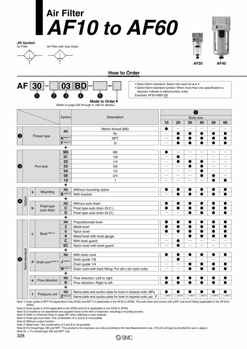
AF 30 03 BD
Air Filter
AF10 to AF60JIS SymbolAir Filter Air Filter with Auto Drain
How to Order
Made to Order(Refer to page 334 through to 336 for details.)
• Option/Semi-standard: Select one each for a to f.• Option/Semi-standard symbol: When more than one specification is
required, indicate in alphanumeric order.Example) AF30-03BD-2R
+
+
+
+
+
+
+
Note 1) Drain guide is NPT1/8 (applicable to the AF20) and NPT1/4 (applicable to the AF30 to AF60). The auto drain port comes with ø3/8" one-touch fitting (applicable to the AF30 to AF60).
Note 2) Drain guide is G1/8 (applicable to the AF20) and G1/4 (applicable to the AF30 to AF60). Note 3) A bracket is not assembled and supplied loose at the time of shipment. Including 2 mounting screwsNote 4) Refer to Chemical Data on page 287 when selecting a case material.Note 5) Float type auto drain: The combination of C and D is not possible.Note 6) Without a valve functionNote 7) Metal bowl: The combination of 2 and 8 is not possible.Note 8) For thread type: M5 and NPT. This product is for overseas use only according to the new Measurement Law. (The SI unit type is provided for use in Japan.)Note 9) �: For thread type: M5 and NPT only
10 20 30 40 50 60Body sizeDescription
Metric thread (M5)Rc
NPTG
Symbol
Nil
N Note 1)
F Note 2)
Thread type
M51/81/43/81/23/41
M5010203040610
Port size
NilB Note 3)
MountingaWithout mounting optionWith bracket
NilR
Flow directioneFlow direction: Left to rightFlow direction: Right to left
NilCD
Float typeauto drain
bWithout auto drainFloat type auto drain (N.C.)Float type auto drain (N.O.)
Nil268C6C
Bowl Note 4)c
Polycarbonate bowlMetal bowlNylon bowlMetal bowl with level gaugeWith bowl guardNylon bowl with bowl guard
Nil
J Note 6)
W Note 7)
Drain port Note 5)d
With drain cockDrain guide 1/8Drain guide 1/4Drain cock with barb fitting: For ø6 x ø4 nylon tube
NilZ Note 8)
Pressure unitfName plate and caution plate for bowl in imperial units: MPaName plate and caution plate for bowl in imperial units: psi, °F Note 9) Note 9) Note 9) Note 9) Note 9) Note 9)
Sem
i-sta
ndar
dO
ptio
n
328
P0295-P0364-E.qxd 08.11.6 2:06 PM Page 328

Standard Specifications
Air–5 to 60°C (with no freezing)
1.5 MPa1.0 MPa
5 μm
Polycarbonate
8
Semi-standard0.18
25
0.22 0.45 0.49 0.99 1.05
452.5
—0.06
Standard
ModelPort sizeFluidAmbient and fluid temperatureProof pressureMaximum operating pressureNominal filtration ratingDrain capacity (cm3)Bowl materialBowl guardMass (kg)
AF10M5 x 0.8
AF201/8, 1/4
AF301/4, 3/8
AF401/4, 3/8, 1/2
AF40-063/4
AF503/4, 1
AF601
Options/Part No.
—AD17
—
AF20P-050ASAD27
—
AF30P-050ASAD37AD38
AD47AD48
AF40P-050AS AF40P-070AS AF50P-050AS AF50P-050ASN.C.N.O.
ModelOptional specifications
Bracket assembly Note 1)
Float type auto drain Note 2) Note 3)
AF10 AF20 AF30 AF40 AF40-06 AF50 AF60
Semi-standard/Bowl Assembly Part No.
Note 1) Assembly of a bracket and 2 mounting screwsNote 2) Minimum operating pressure: N.O. type–0.1 MPa; N.C. type–0.1 MPa (AD17/27) and 0.15 MPa (AD37/47). Please contact SMC for psi and °F unit specifications.Note 3) Please consult with SMC for details on drain piping to fit NPT or G port sizes.Note) • Bowl O-ring is included for the AF20 to AF60.
• Bowl assembly for the AF30 to AF60 models comes with a bowl guard (steel band material). (except when the bowl material is metal)
—
�—————
�—
�————
�———
�——
————————
�——————
�———
�—
——
�—
�—————
�—
�———
�———
�
———
�———————
�—————————
��——
�—
�——
�——
�————————
—————
C1SF-6—
AD17-6—————
C1SF-2AD17-2
——————
N.C. N.O.
ModelSemi-standard specifications
Withbowlguard
Withbarbfitting
Withdrainguide
Note 3)
Float typeauto drain
Note 2) Note 3)
Bowl material
Polycarbonate
Nylon
Metal
Metal bowl withlevel gauge
AF50AF40-06AF40AF30
C2SF-CAD27-CC2SF-J
—C2SF-CJC2SF-6
C2SF-6CAD27-6
—AD27-6CC2SF-6J
—C2SF-6CJ
C2SF-2AD27-2
—C2SF-2J
————
——
C3SF-JC3SF-W
—C3SF-6
—AD37-6AD38-6
—C3SF-6JC3SF-6W
—C3SF-2AD37-2AD38-2C3SF-2JC3LF-8AD37-8AD38-8C3LF-8J
——
C4SF-JC4SF-W
—C4SF-6
—AD47-6AD48-6
—C4SF-6JC4SF-6W
—C4SF-2AD47-2AD48-2C4SF-2JC4LF-8AD47-8AD48-8C4LF-8J
AF20AF10 AF60
329
Air Filter Series AF10 to AF60
AC
AF�
AR
AL
AW�
A�G
AVAF800AF900
P0295-P0364-E.qxd 08.11.6 2:06 PM Page 329

AF20 Rc1/4 AF30 Rc3/8AF10 M5
Flow Characteristics (Representative values)
50 100 150 200
0.10
0.08
0.06
0.04
0.02
00
Flow rate (l/min (ANR))
Pre
ssur
e dr
op (
MP
a)
P1
= 0.
1 M
Pa
P1 = 0
.3 M
PaP1 =
0.5
MPa
P1 = 0
.7 M
Pa
0.10
0.08
0.06
0.04
0.02
00 500 1000 1500
Flow rate (l/min (ANR))
Pre
ssur
e dr
op (
MP
a)
P1
= 0.
1 M
Pa
P1
= 0.
3 M
PaP
1 =
0.5
MPa
P1 = 0
.7 M
Pa
0.10
0.08
0.06
0.04
0.02
00 20001000 3000 4000
Flow rate (l/min (ANR))
Pre
ssur
e dr
op (
MP
a)
P1
= 0.
1 M
Pa
P1
= 0.
3 M
Pa
P1
= 0.
5 M
PaP
1 =
0.7
MPa
0.10
0.08
0.06
0.04
0.02
00
AF50 Rc1
Flow rate (l/min (ANR))P
ress
ure
drop
(M
Pa)
5000 10000 15000
P1
= 0.
1 M
Pa
P1
= 0.
3 M
PaP
1 =
0.5
MPa
P1 = 0
.7 M
Pa
0.10
0.08
0.06
0.04
0.02
00
AF40-06 Rc3/4
Flow rate (l/min (ANR))
Pre
ssur
e dr
op (
MP
a)
2000 4000 6000
P1
= 0.
1 M
Pa
P1 = 0
.3 M
PaP1 =
0.5
MPa
P1 =
0.7
MPa
0.10
0.08
0.06
0.04
0.02
00 2000 4000 6000
AF40 Rc1/2
Flow rate (l/min (ANR))
Pre
ssur
e dr
op (
MP
a)
P1
= 0.
1 M
Pa
P1
= 0.
3 M
PaP
1 =
0.5
MPa
P1
= 0.
7 M
Pa
0.10
0.08
0.06
0.04
0.02
00
AF60 Rc1
Flow rate (l/min (ANR))
Pre
ssur
e dr
op (
MP
a)
5000 10000 15000
P1
= 0.
1 M
Pa
P1
= 0.
3 M
PaP1 =
0.5
MPa
P1 = 0
.7 M
Pa
Be sure to read before handling.Refer to front matters 42 and 43 for Safety Instructions and pages 287 to 291 for F.R.L. Precautions.
Specific Product Precautions
Mounting and Adjustment
1. Replace the element every 2 years or when the pressure drop becomes 0.1 MPa, whichever comes first, to prevent damage to the element.
Warning
330
Series AF10 to AF60
P0295-P0364-E.qxd 08.11.6 2:06 PM Page 330

Working Principle: Float Type Auto Drain
N.C. type: AD37, AD47N.O. type: AD38, AD48 Compact auto drainN.C. type: AD17, AD27
Bowl
Valve
Lever
Float
Valve seat
Chamber
Piston
Spring
Housing
DrainDrain
Seal
Drain cock
q
r
e
w
t
i
u
y
o
!0
!1
Bowl
Valve
Lever
Float
Valve seat
Chamber
Piston
Spring
Housing
Seal
Drain cock
q
r
e
w
t
i
y
u
o
!0
!1 Drain
Bowl
Float
Lever
Valve
Valve seat
Knob
q
w
e
r
t
y
• When pressure inside the bowl is re-leased:Even when pressure inside the bowl q is re-leased, spring y keeps piston u in its upward position. This keeps the seal created by the seal !0 in place; thus, the inside of the bowl q is shut off from the outside air.Therefore, even if there is an accumulation of condensate in the bowl q, it will not drain out.
• When pressure is applied inside the bowl:Even when pressure is applied inside the bowl q, the combined force of spring y and the pressure inside the bowl q keeps piston u in its upward position.This maintains the seal created by the seal !0 in place; thus, the inside of the bowl q is shut off from the outside air.If there is no accumulation of condensate in the bowl q at this time float w will be pulled down by its own weight, causing valve r, which is connected to lever e, to seal valve seat t.
• When there is an accumulation of condensate in the bowl:Float w rises due to its own buoyancy and pushes open the seal created by the valve seat t. Pressure passes from the bowl q to cham-ber i.The result is that the pressure inside chamber i surpasses the force of the spring y and pushes piston u downwards.This causes the sealing action of seal !0 to be interrupted and the accumulated condensate in the bowl q drains out through the drain cock !1.Turning drain cock !1 manually counterclock-wise lowers piston u, which pushes open the seal created by seal !0, thus allowing the con-densate to drain out.
• When pressure inside the bowl is released:When pressure is released from the bowl q, piston u is lowered by spring y.The sealing action of seal !0 is interrupted, and the outside air flows inside the bowl q through housing hole o and drain cock !1.Therefore, if there is an accumulation of con-densate in the bowl q, it will drain out through the drain cock.
• When pressure is applied inside the bowl:When pressure exceeds 0.1 MPa, the force of piston u surpasses the force of spring y, and the piston goes up.This pushes seal !0 up so that it creates a seal, and the inside of the bowl q, is shut off from the outside air.If there is no accumulation of condensate in the bowl q at this time, float w will be pulled down by its own weight, causing valve r, which is connected to lever e, to seal valve seat t.
• When there is an accumulation of condensate in the bowl:Float w rises due to its own buoyancy andpushes open the seal created by the valve seat t.This allows the pressure inside the bowl q to enter the chamber i. The result is that the combined pressure inside chamber i and the force of the spring y lowers the piston u.This causes the sealing action of seal !0 to be interrupted, and the accumulated condensate in the bowl q drains out through the drain cock !1.Turning drain cock !1 manually counterclock-wise lowers piston u, which pushes open the seal created by seal !0, thus allowing the con-densate to drain out.
• When pressure inside the bowl is released:Even when pressure inside the bowl q is released, the weight of the float w causes valve r, which is connected to lever e, to seal valve seat t. As a result, the inside of the bowl q is shut off from the outside air.Therefore, even if there is an accumulation of condensate in the bowl q, it will not drain out.
• When pressure is applied inside the bowl:Even when pressure is applied inside the bowl q, the weight of the float w and the differential pressure that is applied to valve r cause valve r to seal valve seat t, and the outside air is shut off from the inside of the bowl q.
• When the drain is accumulated in the bowl:Float w rises due to its own buoyancy and the seal at valve seat t is interrupted.The condensate inside the bowl q drains out through the knob y.Turning knob y manually counterclockwise lowers it and causes the sealing action of valve seat t to be interrupted, which allows the condensate to drain out.
331
Air Filter Series AF10 to AF60
AC
AF�
AR
AL
AW�
A�G
AVAF800AF900
P0295-P0364-E.qxd 08.11.6 2:06 PM Page 331

Construction
AF10, AF20 AF30 to AF40-06 AF50, AF60
Component PartsNo. Description
Body
Housing
Material
Zinc die-cast
Aluminum die-cast
Aluminum die-cast
Model
AF10, AF20
AF30 to AF60
AF50, AF60
Platinum silver
Platinum silver
Color
1
6
No. Description
Filter element
Baffle
Bowl O-ring
Bowl assembly Note 2)
Material
Non-woven fabric
PBT
NBR
Polycarbonate
Part no.
AF10 AF20 AF30 AF40 AF40-06 AF50 AF60AF10P-060S
AF10P-040S Note 1)
C1SFP-260S
C1SF
AF20P-060S
AF20P-040S
C2SFP-260S
C2SF
AF30P-060S
AF30P-040S
C3SFP-260S
C3SF Note 3)
AF40P-060S
AF40P-040S
C4SFP-260S
C4SF Note 3)
AF50P-060S
AF50P-040S
AF60P-060S
AF60P-040S
2
3
4
5
Replacement Parts
Note 1) The material of the baffle for the AF10 (AF10P-040S) only is polyacetal.Note 2) Bowl O-ring is included. Please contact SMC regarding the bowl assembly supply for psi and °F unit specifications.Note 3) Bowl assembly for the AF30 to AF60 models comes with a bowl guard (steel band material).
OUTIN
q
y
w
r
e
t
OUTIN
q
r
w
e
t
IN OUT
q
r
w
e
t
Drain
Drain
Drain
332
Series AF10 to AF60
P0295-P0364-E.qxd 08.11.6 2:06 PM Page 332

B B
B
B
B B
B BVQ
D
MJ
U
V
B
E
DJ
Q
A
T
GR
C
MUN
S
VQ
D
JU
GM
A
RB
CTN
S
BA G
T
NS
RC
Dimensions
AF10, AF20 AF50, AF60
AF30 to AF40-06
o s
IN OUT
2 x P(Port size)
Cle
aran
ce fo
rm
aint
enan
ce
Drain
OUT
Bracket(Option)
2 x P(Port size)
Bracket(Option)
IN OUT
Cle
aran
ce fo
rm
aint
enan
ceDrain
IN
2 x P(Port size)
Bracket(Option)
Cle
aran
ce fo
rm
aint
enan
ce
OUT
Drain
OUT
With drain guide Drain cock with barb fittingWith drain guideMetal bowl with level gaugeWith auto drain (N.O./N.C.)Metal bowlWith auto drain (N.C.)Optional/Semi-standardspecifications Metal bowl
Dimensions
Applicable model AF10/20 AF20 AF30 to AF60
M5 x 0.81/8
Width across flats 14
N.O.: BlackN.C.: Gray
ø10 one-touch fitting Width across flats 17
1/4Barb fitting
Applicable tubing: T0604
ModelStandard specifications
Optional specifications
PM5 x 0.8
1/8, 1/4
1/4, 3/8
1/4, 3/8, 1/2
3/4
3/4, 1
1
A25
40
53
70
75
90
95
B 67
97
129
165
169
245
258
C 7
10
14
18
20
24
24
D12.5
20
26.5
35
35
45
47.5
E—
—
30
38
38
—
—
G25
40
50
75
75
20
20
J12.5
20
26.5
35
35
45
47.5
M—
30
41
50
50
70
70
N—
27
40
54
54
66
66
Q—
22
23
26
25
35
35
R—
5.4
6.5
8.5
8.5
11
11
S—
8.4
8
10.5
10.5
13
13
T—
40
53
70
70
90
90
U—
2.3
2.3
2.3
2.3
3.2
3.2
V—
28
30
35
34
47
47
B 85
115
170
204
208
284
297
AF10AF20AF30AF40AF40-06AF50AF60
Model
Semi-standard specifications
Bracket mount With auto drain
With barb fitting With drain guide Metal bowl Metal bowl withlevel gauge
B—
—
137
173
177
253
266
B—
101
136
172
176
252
265
B 66
97
142
178
182
258
271
B—
—
162
198
202
278
291
AF10AF20AF30AF40AF40-06AF50AF60
OUT
O S
O
S
333
Air Filter Series AF10 to AF60
AC
AF�
AR
AL
AW�
A�G
AVAF800AF900
P0295-P0364-E.qxd 08.11.6 2:06 PM Page 333

Air FilterAF10 to AF60Made to Order Specifications:Please contact SMC for detailed dimensions, specifications, and lead times.
q Special Temperature EnvironmentSpecial materials are used in the manufacturing of seals and resin parts to allow them to withstand various temperature conditions in cold or tropical (hot) climates.
Specifications
Environment
Ambient temperature (°C)
Fluid temperature (°C)
Material
Low temperature
–30 to 60
Special NBR
–5 to 60 (with no freezing)
Metal (Aluminum die-cast, etc.)
Made-to-order no. -X430High temperature
–5 to 80
FKM
-X440
Rubber parts
Main parts
w High PressureStrong materials are used in the manufacturing of air filters intended for high pressure operation.
Note 1) Drain guide is NPT1/8 (applicable to the AF20) and NPT1/4 (applicable to the AF30 to AF60.
Note 2) Drain guide is G1/8 (applicable to the AF20) and G1/4 (applicable to the AF30 to AF60).
Note 3) A bracket is not assembled and supplied loose at the time of shipment. Including 2 mounting screws
Note 4) Only metal bowl 2 and 8 are available.Note 5) Without a valve functionNote 6) For thread type: NPT. This product is for overseas use only according to the
new Measurement Law. (The SI unit type is provided for use in Japan.)Note 7) �: For thread type: NPT only
30AF X425203 B
For high pressure
Applicable Model
Port size
Model AF30 AF40 AF40-06 AF501/4, 3/8 1/4, 3/8, 1/2 3/4 3/4, 1
AF601
Applicable Model
Port size
Model AF20 AF40 AF40-06 AF501/8, 1/4
AF301/4, 3/8 1/4, 3/8, 1/2 3/4 3/4, 1
AF601
Specifications
3.0
2.0
–5 to 60 (with no freezing)
Made-to-order no. -X425Proof pressure (MPa)
Maximum operating pressure (MPa)
Ambient and fluid temperature (°C)
Note 1) Drain guide is NPT1/4.Note 2) Drain guide is G1/4.Note 3) A bracket is not assembled and supplied loose at the time of shipment.
Including 2 mounting screwsNote 4) Only metal bowl 2 is available.Note 5) Without a valve functionNote 6) For thread type: NPT. This product is for overseas use only according to the
new Measurement Law. (The SI unit type is provided for use in Japan.)Note 7) �: For thread type: NPT only
30AF 203 B
X430X440
For high/lowtemperatureLow temperatureHigh temperature
X430
30 40 50 6020Body sizeDescription
RcNPT
G
Symbol
NilN Note 1)
F Note 2)
Thread type
1/81/43/81/23/41
010203040610
Port size
Metal bowlMetal bowl with level gauge
28
Bowl Note 4)
+
+
Note 7) Note 7) Note 7) Note 7)
Name plate and caution plate for bowl in imperial units: MPaName plate and caution plate for bowl in imperial units: psi, °F
30 40 50 60Body sizeDescription
RcNPT
G
Symbol
NilN Note 1)
F Note 2)
Thread type
1/43/81/23/41
0203040610
Port size
Metal bowl2Bowl Note 4)
With drain cockDrain guide 1/4
NilJ Note 5)
Drainporta
Flow direction: Left to rightFlow direction: Right to left
NilR
Flowdirectionb
Nil
Z Note 6)
Pressureunitc
+
+
+
+
+
Without mounting optionWith bracket
NilB Note 3)
Option(Mounting)
+ Without mounting optionWith bracket
NilB Note 3)
Option(Mounting)
+
Name plate and caution plate for bowl in imperial units: MPaName plate and caution plate for bowl in imperial units: psi, °F
With drain cockDrain guide 1/8Drain guide 1/4
Nil
J Note 5)
Drainporta
Flow direction: Left to rightFlow direction: Right to left
NilR
Flowdirectionb
Nil
Z Note 6)
Pressureunitc
+
+
+
Note 7) Note 7) Note 7) Note 7) Note 7)
• Semi-standard: Select one each for a to c.• Semi-standard symbol: When more than
one specification is required, indicate in alphanumeric order.
Example) AF30-03B-2R-X430
Sem
i-sta
ndar
d
Sem
i-sta
ndar
d
• Semi-standard: Select one each for a to c.• Semi-standard symbol: When more than one specification is required,
indicate in alphanumeric order.Example) AF30-03B-2R-X425
334
P0295-P0364-E.qxd 08.11.6 2:06 PM Page 334

+
+
+
+
+
+
Note 1) Drain guide is NPT1/8 (applicable to the AF20) and NPT1/4 (applicable to the AF30 to AF60).
Note 2) Drain guide is G1/8 (applicable to the AF20) and G1/4 (applicable to the AF30 to AF60).
Note 3) A bracket is not assembled and supplied loose at the time of shipment. Including 2 mounting screws
Note 4) Refer to Chemical Data on page 287 when selecting a case material.Note 5) Without a valve functionNote 6) Metal bowl: The combination with 2 is not possible.Note 7) For thread type: M5, NPT. This product is for overseas use only according to
the new Measurement Law. (The SI unit type is provided for use in Japan.) Note 8) �: For thread type: M5, NPT only
Note) Please consult with SMC for dimensions.
10 20 30 40 50 60Body sizeDescription
Metric thread (M5)Rc
NPTG
Symbol
Nil
N Note 1)
F Note 2)
Thread type
M51/81/43/81/23/41
M5010203040610
Port size
NilB Note 3)
Option (Mounting)Without mounting optionWith bracket
NilR
Flow directioncFlow direction: Left to rightFlow direction: Right to left
Nil26C6C
Bowl Note 4)a
Polycarbonate bowlMetal bowlNylon bowlWith bowl guardNylon bowl with bowl guard
Nil
J Note 5)
W Note 6)
Drain portb
With drain cockDrain guide 1/8Drain guide 1/4Drain cock with barb fitting: For ø6 x ø4 nylon tube
NilZ Note 7)
Pressure unitdName plate and caution plate for bowl in imperial units: MPaName plate and caution plate for bowl in imperial units: psi, °F
e Long BowlDrain capacity is greater than that of standard models.
30AF X6403
Long bowl
Applicable Model/Drain Capacity
Port size
Drain capacity (cm3)
Model AF10 AF30 AF40 AF40-06M5
9
AF201/8, 1/4
19
1/4, 3/8
43
1/4, 3/8, 1/2 3/4
88
AF503/4, 1
AF601
• Semi-standard: Select one each for a to d.• Option/Semi-standard symbol: When more than one specification is required, indicate in alphanumeric order.Example) AF30-03B-2R-X64
Sem
i-sta
ndar
d
Note 8) Note 8) Note 8) Note 8) Note 8) Note 8)
335
Air Filter Series AF10 to AF60
AC
AF�
AR
AL
AW�
A�G
AVAF800AF900
P0295-P0364-E.qxd 08.11.6 2:06 PM Page 335

Air FilterAF30 to AF60Made to Order Specifications:Please contact SMC for detailed dimensions, specifications, and lead times.
+
+
+
+
+
+
+
Note 1) Drain guide is NPT1/4.The auto drain port comes with ø3/8" One-touch fitting.
Note 2) Drain guide is G1/4.Note 3) Option B is not assembled and supplied loose at the time of shipment.
Including 2 mounting screwsNote 4) Refer to Chemical Data on page 287 when selecting a case material.Note 5) Float type auto drain: The combination of C and D is not possible.
Note 6) Without a valve functionNote 7) Metal bowl: The combination of 2 and 8 is not possible.Note 8) For thread type: NPT. This product is for overseas use only according to the
new Measurement Law. (The SI unit type is provided for use in Japan.) Note 9) �: For thread type: NPT only
30 40 50 60Body sizeDescription
RcNPT
G
Symbol
NilN Note 1)
F Note 2)
Thread type
1/43/81/23/41
0203040610
Port size
NilB Note 3)
Without mounting optionWith bracket
NilR
Flow directioneFlow direction: Left to rightFlow direction: Right to left
Mountinga
NilCD
Without auto drainFloat type auto drain (N.C.)Float type auto drain (N.O.)
Float typeauto drainb
Nil268
Bowl Note 4)c
Polycarbonate bowlMetal bowlNylon bowlMetal bowl with level gauge
NilJ Note 6)
W Note 7)
Drain port Note 5)dWith drain cockDrain guide 1/4Drain cock with barb fitting: For ø6 x ø4 nylon tube
Note 9) Note 9)Note 9) Note 9)
NilZ Note 8)
Pressure unitfName plate and caution plate for bowl in imperial units: MPaName plate and caution plate for bowl in imperial units: psi, °F
r With Element Service IndicatorClogging status of elements can be checked visually.
30AF X214103
With element service indicator
A special body type is required to mount the clogging checker. It cannot be mounted on a standard body.
Applicable Model
Port size
Model
1/4, 3/8 1/4, 3/8, 1/2 3/4 1
AF30 AF40-06 AF50 AF60AF403/4, 1
• Option/Semi-standard: Select one each for a to f.• Option/Semi-standard symbol: When more than one specification is required, indicate in alphanumeric order.Example) AF30-03BD-2R-X2141
Sem
i-sta
ndar
dO
ptio
n
336
P0295-P0364-E.qxd 08.11.6 2:06 PM Page 336

How To Order Series VHS 20 to 40
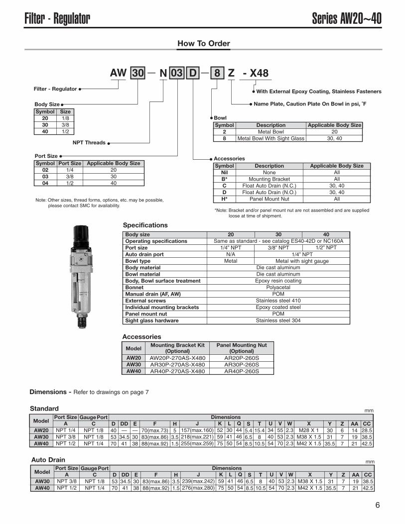
How To OrderRegulator Series AR 20 to 40
How To Order Series AF 20 to 40
AF 30 N 03 - X480
Filter
Body Size
Symbol
203040
Size
1/83/81/2
NPT Threads
Port Size
1/43/81/2
Symbol
020304
Applicable Body Size
203040
Port Size
Z8D
With External Epoxy Coating, Stainless Fasteners
Name Plate, Caution Plate On Bowl in psi, °F
Symbol
28
Description
Metal BowlMetal Bowl with Sight Glass
Applicable Body Size
2131, 41
Bowl
Description
NoneMounting Bracket
Float Auto Drain (N.C.)Float Auto Drain (N.O.)
Applicable Body Size
AllAll
31, 4131, 41
Symbol
NilB*CD
Accessories
AR N - X48
Symbol
NilB*H*
N NPT
VHS 30 N 03 Z - X513
Residual Pressure Relief Valve
Body Size
Symbol
203040
Applicable Model
AC21AC31AC41
Port Size
1/43/81/2
Symbol
020304
Body Size
Port Size
20 30 40
Thread Type
Name Plate in imperial Units (psi, °F)
With External Epoxy Coating Stainless Fasteners
Regulator
NPT Threads
Port Size
1/43/81/2
Symbol
020304
Applicable Body Size
203040
Port Size
Note: Other sizes, thread forms, options,
etc. may be possible, please
contact SMC for availability.
Body Size
Symbol
203040
Size
1/83/81/2
With External Epoxy Coating Stainless Fasteners
Name Plate in imperial Units (psi, °F)
Symbol
NilY
Description
Handle DownHandle Up
Handle Orientation
Accessories
*Note: Bracket and/or panel mount nut are not assembled and are supplied loose at time of shipment.
Description
NoneMounting BracketPanel Mount Nut
*Note: Bracket is not assembled and is supplied loose at time of shipment.
20 02 B Y Z
Filter
Residual Pressure Relief Valve

Pre
ssur
e dr
op (
MP
a)P
ress
ure
drop
(M
Pa)
AF800
How to Order
1 4
12AF 008
121420
1 2
1 4
2
11
Port size
Thread type
Option
NilNF
RcNPT
G
DDrain cock thread piping
{Rc 1/4}Drain guide
Flow direction: Right to left
Body size
Air filter
Auto-drain specifications
89
1 212
001011
NoneFloat type auto drain (N.C.)Float type auto drain (N.O.)
127 R
Option
6789
Optional filtration rateMetal bowlNylon bowl Stainless steel elementMetal bowl with level gaugeWithout drain cock
21
168
Rc1 4NPT
1 4G
Standard SpecificationsModel
Port size
Proof pressure
Filtration
Bowl material
Ambient andfluid temperature
Maximum operating pressure
Bowl capacity (cm3)
Mass (kg)
Accessory (Standard)
AF900
1 2
AF800
1
1 412
5.453.15
1.5 MPa
Accessory (Option)/Part No.
Description
N.O
N.C
Part no.
Float type auto drain ∗(Bowl assembly)
AF9AF8
AD34 (Bowl material: Nylon)
AD16M (Bowl material: Polycarbonate)AD16M (Bowl material: Polycarbonate)
AD34 (Bowl material: Nylon)
1.0 MPa
Standard specifications: 5 μm Option: 2, 10, 20, 40, 70, 100 μm
Polycarbonate
Bowl guard
180 cm3
–5 to 60°C (No freezing)
∗ Min. operating pressure: 0.1 MPa (N.O.), 0.15 MPa (N.C.)
Flow Characteristics (Representative Values)
AF900 (Representative Values)
Model
Note 1) When specifiying more than one number, indicate them in numerical order.(Ex.) 127-40
Note 2) When specifying more than one alphabet symbol, indicate them alphabetically and put “–” between them. (Ex.) D-R
Note 3) Options for “2”, “6”, and “8” can not be specified at the same time. (Ex.) 68
Note 4) Symbols “9”, “D”, “J” can not be specified at the same time. (Ex.) 9-D-J
Note 5) For products with auto drain, either symbol “D” or “J” cannot be specified at the same time because of female threads (3/8 or 1/8), for connection to drain piping.
Note 6) For N.C. type with auto drain, metal case with liquid level indicator is not available.
∗ 1 Indicate the required filtration rate after the symbol “1”. Ex.) When 40 μm is rquired: 1-40
∗ 2 If indicating “7” only, the filtration rate is 5 μm. Optional filtration rate is required, indicate like 17-�.Ex.) When requiring “stainless steel
and 40 μm”; 17-40∗ 3 The bowl of series AL is used.∗ 4 This symbol “�” indicates the port
size.
∗2
∗3
∗1
JR
∗4
Flow rate (l/min (ANR))
Flow rate (l/min (ANR))
445
Large Flow Air Filter
Series AF800/900
AC
AF�
AR
AL
AW�
A�G
AVAF800AF900
P0365-P0446-E.qxd 08.11.6 2:09 PM Page 445

Metal bowl Metal bowl with level gauge Drain cock thread piping
Without drain cock With drain guide
Mai
nten
ance
spa
ce
Port size
Push button
Option
Model Metalbowl
Metal bowlwith level gauge
Without drain cock
Drain cockthread piping
With drain guide
AF800AF900
409489
440.5520.5
393.5473.5
410490
406.5486.5
B (Without auto drain)
Option/Dimensions
Model A B C DN.O N.C
E
AF800AF900
150200
410490
3346
140170
439519
440520
200260
B (With auto drain)
PipingWarning
SelectionWarning
PrecautionsBe sure to read before handling. Refer to front matters 42 and 43 for Safety Instructions and pages 287 to 291 for F.R.L. Precautions.
Replacement PartsPart no.
Qty.AF800 AF900
11345-5B11345-5S
113136112171134611344
—
AF11-4(11316A)AF11-4-2
AF11-4-6-(1131123A)AF-8
AF11-4-9(123120)
11352-5B11352-5S
630332
11313611231011355
—11354
11
1
1
121
1
No. Description Material
Element
Bowl assembly
O-ring
O-ringElement sealDeflector
Buffer
Standard-7
Standard-2-6-8-9
AF800AF900
BronzeStainless steel
—————
NBR
NBRNBR
AluminumADC
Aluminum casted
2
3
4
578
9
JIS B2401G130
Component PartsMaterial
AF800 AF900No. Description Note
BodyHousing
Aluminum die-castedAluminum die-casted
Aluminum castedAluminum casted
Platinum silver paintedPlatinum silver painted
16
Dimensions
Construction
∗
∗
∗
Use auto drain under the following conditions.Otherwise, it may result in a malfunction.
1. Float type auto drain (N.O.)1) Use compressor with capacity more than 3.7 kW {400 l/min (ANR)}2) Set operating pressure more than 0.1 MPa.
2. Float type auto drain (N.C.)1) Compressor can be used even if energy is under 3.7 kW.2) Set operating pressure more than 0.15 MPa.
Be sure to pipe auto drain under the following conditions.Otherwise, it may result in a malfunction.
1. Float type auto drain (N.O.)When making drain exhaust piping, use piping with bore size ø10 or larger than ø10.Length should be shorter than 5 m. Do NOT make upward piping.
2. Float type auto drain (N.C.)DO NOT pipe upwards.
∗ A bowl, bowl guard, clamp ring and drain cock are assembled. ( ): A bowl and a drain cock are assembled. -9 does not include a drain cock.
446
Series AF800/900
P0365-P0446-E.qxd 08.11.6 2:09 PM Page 446

P.G. Information
Epoxy Coated F.R.L.Units
AC21/31/41-***-*-X2217AF20/30/40-***-*-X480AR20/30/40-***-*-X48AL20/30/40-***-*-X480AW20/30/40-***-*-X48VHS20/30/40-***-*-X513Y20/30/40*-T4
Application: Air preparation in an environment that requires enhanced corrosion protection.
Feature 1: Die cast aluminum components are epoxy coated for improved chemical resistance.
Feature 2: Steel external hardware is replaced with stainless steel for improved chemicalresistance.
Comparison with Standard Product:
1) Functional performance is equivalent to standard product.
2) Product withstood salt spray testing per ASTM B117-07A with excellent results(See test results on page 12). Improved performance vs. other chemicals isanticipated but has not been verified.
Applications:
• Marine environments
• Water splash zone in various processes
• Washdown in food plants (non-food or splash zone only)
Related Products:
• KQG Series - 316 SUS One-touch Fittings - Coming Soon: KQG2
• KQB2 Series - Ni plated brass One-touch Fittings (Coming Soon)
• ASG Series - 316 SUS One-touch Speed Controls
• CG5 Series - repairable 304 SUS Cylinder
• NCM Series with X6009 option - crimped body 304 SUS Cylinder, domesticinterchange
• CJ5 Series - crimped body 304 SUS Cylinder
• HY Series - Aluminum body Hygienic Design Actuators
SP093-001I
Issued: Sep 2009
SMC Corporation of America10100 SMC BoulevardNoblesville, IN 46060
www.smcusa.com

Series AC21~41F.R.L. Unit
2
How To Order
AC 31 B N 03 D V 8 Y Z - X2217— — —
Air Combination Unit
Note: Other sizes, thread forms, options, etc. may be possible,please contact SMC for availability.
With External Epoxy Coating, Stainless Fasteners
Name Plate, Caution Plate On Bowl in psi, ˚F
NPT Threads
Body SizeSymbol
213141
Size1/83/81/2
Model CombinationSymbol
NilAB
Model / Assembly OrderAF + AR + ALAW + ALAF + AR
Port SizeSymbol
020304
Port Size1/43/81/2
Applicable Body Size213141
SpecificationsBody sizeOperating specificationsPort sizeAuto drain port (AF, AW)Bowl type (AF, AL, AW)Body materialBowl material (AF, AL, AW)Body, Bowl surface treatmentBonnet (AR, AW)Manual drain (AF, AW)External screwsIndividual mounting bracketsPanel mount nut (AR, AW)Connector brackets (AC)Fill plug (AL)Sight dome (AL)Sightglasshardware (AF,AL,AW)
21 31 41
AC21AC31AC41
AC A*140181238
AA**190245322
B160220239
C738692
E—3038
F45.558.575.5
G405580
J2629.537.5
K53.51.5
M304150
N516481
Q243540
U577
V334550
W—34.541
Same as standard - see catalog ES40-42D or NC160A1/4” NPTN/AMetal
1/4” NPTMetal with sight gauge
Die cast aluminumDie cast aluminumEpoxy resin coating
PolyacetalPOM
Stainless steel 410Epoxy coated steel
POMDie cast zinc (epoxy coated)
Stainless steel 304Polycarbonate
Stainless steel 304
3/8” NPT 1/2” NPT
BowlSymbol
28
DescriptionMetal Bowl
Metal Bowl With Sight Glass
Applicable Body Size21
31, 41
Residual Pressure Relief ValveSymbol
NilV
DescriptionWithout Valve
With Downstream Valve
Applicable Model ComboAllAll
AccessoriesSymbol
NilCD
DescriptionNone
Float Auto Drain (N.C.)Float Auto Drain (N.O.)
Applicable Body SizeAll
31, 4131, 41
Regulator Handle OrientationSymbol
NilY
DescriptionDownward HandleUpward Handle
Dimensions - Refer to drawings on page 3 mm
AC21AAC31AAC41A
A*90117154
AA**140181238
B160220239
C738692
E—3038
F45.558.575.5
G405580
J2629.537.5
K53.51.5
M304150
N516481
Q243540
U577
V334550
W—34.541
mm
AC21BAC31BAC41B
A*90117154
AA**140181238
B160220239
C738692
E—3038
F45.558.575.5
G405580
J2629.537.5
K53.51.5
M304150
N516481
Q243540
U577
V334550
W—34.541
mm
AC-A
AC-B
* Without relief valve option ** With relief valve option
* Without relief valve option ** With relief valve option
* Without relief valve option ** With relief valve option

3
Series AC21~41 F.R.L. UnitAC AA
NF
C
B
E
G
K
W
U
QQV
M J
(2) - P1(Port Size)
P2(GaugePort Size)
Min
.Cle
aran
ceF
or
Mai
nte
nan
ce
IN OUT
Bracket andRelief Valve(Optional)
A
AC-A AA
NF
C
B
EG
K
W
U
QQV
M J
(2) - P1(Port Size)
P2(GaugePort Size)
Min
.Cle
aran
ceF
or
Mai
nte
nan
ce
IN OUT
A
Bracket andRelief Valve(Optional)
AC-B AA
NF
CB
E
G
K
W
U
QQV
M J
(2) - P1(Port Size)
P2(GaugePort Size)
Min
.Cle
aran
ceF
or
Mai
nte
nan
ce
IN OUT
Bracket andRelief Valve(Optional)
A
Note: Sight glass notapplicable to all size 20bowls.
Notes: Filter & Filter Regulator Bowls depict manual drain, see individual sections for details with auto-drain options.
D
Bowl Detail(AF20/AW20)

4
Series AF20~40FilterHow To Order
AF 30 N 03 D 8 Z - X480— —
Filter
Note: Other sizes, thread forms, options, etc. may be possible,please contact SMC for availability. *Note: Bracket is not assembled and is supplied loose at time of shipment.
With External Epoxy Coating, Stainless Fasteners
Name Plate, Caution Plate On Bowl in psi, ˚F
NPT Threads
Body SizeSymbol
203040
Size1/83/81/2
Port SizeSymbol
020304
Port Size1/43/81/2
Applicable Body Size203040
SpecificationsBody sizeOperating specificationsPort sizeAuto drain portBowl typeBody materialBowl materialBody, Bowl surface treatmentManual drain (AF, AW)External screwsIndividual mounting bracketsSight glass hardware
20 30 40
AF20AF30AF40
ANPT 1/4NPT 3/8NPT 1/2
C405370
Same as standard - see catalog ES40-42D or NC160A1/4” NPTN/AMetal
1/4” NPTMetal with sight gauge
Die cast aluminumDie cast aluminumEpoxy resin coating
POMStainless steel 410Epoxy coated steelStainless steel 304
3/8” NPT 1/2” NPT
BowlSymbol
28
DescriptionMetal Bowl
Metal Bowl With Sight Glass
Applicable Body Size20
30, 40
AccessoriesSymbol
NilB*CD
DescriptionNone
Mounting BracketFloat Auto Drain (N.C.)Float Auto Drain (N.O.)
Applicable Body SizeAllAll
30, 4030, 40
Dimensions Mounting Bracket Kit(Optional)
AF20P-050AS-X480AF30P-050AS-X480AF40P-050AS-X480
ModelPort Size
D97149185
E101418
F405370
G—5773
H181617
J304150
K274054
L222326
M5.46.58.5
N8.4810.5
P405370
Q2.32.32.3
R263547
S324460
W—34.541
TM4 X 0.7M4 X 0.7M5 X 0.8
AF30AF40
ANPT 3/8NPT 1/2
C5370
Dimensions Mounting Bracket Kit(Optional)
AF30P-050AS-X480AF40P-050AS-X480
ModelPort Size
D158194
E1418
F5370
G5773
H1617
J4150
K4054
L2326
M6.58.5
N810.5
P5370
Q2.32.3
R3547
S4460
W34.541
TM4 X 0.7M5 X 0.8
Auto Drain
Standard
Dimensions - Refer to drawings on page 5
mm
mm

5
Series AF20~40 FilterStandard(Manual Drain)
RC
4 - TBRACKETMOUNTING THREAD
S F
WM
IN OUT
PKN 2 - A
U
D
GJ Q
HLE
Bracket(Optional)
With Auto Drain
RC
4 - TBRACKETMOUNTING THREAD
S F
WM
IN OUT
PKN 2 - A
D
GJ Q
H
LE
NPT 1/4
Bracket(Optional)
D
Note: Sight glass notapplicable to AF20.
Bowl Detail U(AF20)
6
Series AW20~40Filter - RegulatorHow To Order
AW 30 N 03 D 8 Z - X48— —
Filter - Regulator
Note: Other sizes, thread forms, options, etc. may be possible,please contact SMC for availability.
With External Epoxy Coating, Stainless Fasteners
Name Plate, Caution Plate On Bowl in psi, ˚F
NPT Threads
Body SizeSymbol
203040
Size1/83/81/2
Port SizeSymbol
020304
Port Size1/43/81/2
Applicable Body Size203040
SpecificationsBody sizeOperating specificationsPort sizeAuto drain portBowl typeBody materialBowl materialBody, Bowl surface treatmentBonnetManual drain (AF, AW)External screwsIndividual mounting bracketsPanel mount nutSight glass hardware
20 30 40Same as standard - see catalog ES40-42D or NC160A1/4” NPTN/AMetal
1/4” NPTMetal with sight gauge
Die cast aluminumDie cast aluminumEpoxy resin coating
PolyacetalPOM
Stainless steel 410Epoxy coated steel
POMStainless steel 304
3/8” NPT 1/2” NPT
BowlSymbol
28
DescriptionMetal Bowl
Metal Bowl With Sight Glass
Applicable Body Size20
30, 40
AccessoriesSymbol
NilB*CDH*
DescriptionNone
Mounting BracketFloat Auto Drain (N.C.)Float Auto Drain (N.O.)Panel Mount Nut
Applicable Body SizeAllAll
30, 4030, 40All
AW30AW40
ANPT 3/8NPT 1/2
DimensionsModel
Port SizeC
NPT 1/8NPT 1/4
GaugePortD5370
DD34.541
E3038
F83(max.86)88(max.92)
H3.51.5
J239(max.242)276(max.280)
K5975
L4150
Q4654
S6.58.5
U4054
T810.5
V5370
W2.32.3
XM38 X 1.5M42 X 1.5
Y3135.5
Z77
AA1921
CC38.542.5
AW20AW30AW40
ANPT 1/4NPT 3/8NPT 1/2
DimensionsModel
Port SizeC
NPT 1/8NPT 1/8NPT 1/4
GaugePortD405370
DD—34.541
E—3038
F70(max.73)83(max.86)88(max.92)
H53.51.5
J157(max.160)218(max.221)255(max.259)
K525975
L304150
Q444654
S5.46.58.5
U344054
T15.4810.5
AW20AW30AW40
Mounting Bracket Kit(Optional)
AW20P-270AS-X480AR30P-270AS-X480AR40P-270AS-X480
Model
V555370
W2.32.32.3
XM28 X 1M38 X 1.5M42 X 1.5
Y303135.5
Z677
AA141921
CC28.538.542.5
Panel Mounting Nut(Optional)
AR20P-260SAR30P-260SAR40P-260S
Auto Drain
Standard
Accessories
Dimensions - Refer to drawings on page 7
mm
mm
*Note: Bracket and/or panel mount nut are not assembled and are suppliedloose at time of shipment.

7
Series AW20~40 Filter - RegulatorStandard(Manual Drain)
C
IN OUT
2 - A
H
IN OUT
AA
Z CC
PANEL FITTING
DD
E EE
J
Y QF
W
KL
X
VU
TS
D
Bracket andMounting Nut(Optional)
With Auto Drain
C
IN OUT
2 - A
H
IN OUT
AA
Z CC
PANEL FITTING
DD
E
J
Y QF
W
KL
X
VU
T
S
D
Bracket andMounting Nut(Optional)
J
Bowl Detail EE(AW20)
Note: Sight glass notapplicable to AW20.

8
Series AR20~40RegulatorHow To Order
AR 20 N 02 B Y Z - X48— —
Regulator
Note: Other sizes, thread forms, options,etc. may be possible, pleasecontact SMC for availability.
With External Epoxy Coating, Stainless Fasteners
Name Plate, Caution Plate On Bowl in psi, ˚F
NPT Threads
Body SizeSymbol
203040
Size1/83/81/2
Port SizeSymbol
020304
Port Size1/43/81/2
Applicable Body Size203040
SpecificationsBody sizeOperating specificationsPort sizeBody materialBody, Bowl surface treatmentBonnetIndividual mounting bracketsPanel mount nut
20 30 40Same as standard - see catalog ES40-42D or NC160A1/4” NPT
Die cast aluminumEpoxy resin coating
PolyacetalEpoxy coated steel
POM
3/8” NPT 1/2” NPT
Handle OrientationSymbol
NilY
DescriptionHandle DownHandle Up
AccessoriesSymbol
NilB*H*
DescriptionNone
Mounting BracketPanel Mount Nut
AR20AR30AR40
ANPT 1/4NPT 3/8NPT 1/2
DimensionsModel
Port SizeC
NPT 1/8NPT 1/8NPT 1/4
GaugePortD405370
E575968
F26.53136
H-23.53.5
J91(max.94)113(max.116)124(max.128)
K304150
L656674
M37.537.542.5
P444654
S15.4810.5
Q5.46.58.5
AR20AR30AR40
Mounting Bracket Kit(Optional)
AR20P-270AS-X48AR30P-270AS-X48AR40P-270AS-X48
Model
T344054
U555370
WM28 X 1M38 X 1.5M42 X 1.5
X677
Y141921
Z28.538.542.5
AA253135.5
Panel Mounting Nut(Optional)
AR20P-260SAR30P-260SAR40P-260S
V2.32.32.3
C
IN OUT
2 - AH
IN OUT
AA
X Z
PANEL FITTING
E
J
Y
Q
F
W
K
V
UT
S
D
P
Plate ThicknessAR20, 30: Max 3.5AR40: Max 5
Bracket andMounting Nut(Optional)
Dimensions
Accessories
mm
*Note: Bracket and/or panel mount nut arenot assembled and are suppliedloose at time of shipment.

9
Series AL20~40 LubricatorHow To Order
AL 20 N 02 B 2 Z - X480— —Lubricator
Note: Other sizes, thread forms, options, etc. may be possible, please contact SMC for availability.
With External Epoxy Coating,Stainless Fasteners
Name Plate, Caution PlateOn Bowl in psi, ˚F
NPT Threads
Body SizeSymbol
203040
Size1/83/81/2
Port SizeSymbol
020304
Port Size1/43/81/2
Applicable Body Size203040
BowlSymbol
28
DescriptionMetal Bowl
Metal Bowl With Sight Glass
Applicable Body Size20
30, 40
AccessoriesSymbol
NilB*
DescriptionNone
Mounting Bracket
Applicable Body SizeAllAll
Specifications
Dimensions
Body sizeOperating specificationsPort sizeBowl typeBody materialBowl materialBody, Bowl surface treatmentIndividual mounting bracketsFill plugSight domeSight glass hardware
20 30 40Same as standard - see catalog ES40-42D or NC160A1/4” NPTMetal
Die cast zincMetal with sight gaugeDie cast aluminum
Die cast aluminumEpoxy resin coatingEpoxy coated steelStainless steel 304Polycarbonate
Stainless steel 304
3/8” NPT 1/2” NPT
AL20AL30AL40
ANPT 1/4NPT 3/8NPT 1/2
C405370
Dimensions Mounting Bracket Kit(Optional)
AF20P-050AS-X480AF30P-050AS-X480AF40P-050AS-X480
ModelPort Size
D121162196
E363840
F405370
G—5773
H283035
J304150
K274054
L222326
M5.46.58.5
N8.4810.5
P405370
Q2.32.32.3
R263547
S324460
W—34.541
TM4 X 0.7M4 X 0.7M5 X 0.8
RC
4 - TBRACKETMOUNTING THREAD
S F
WM
IN OUT
PK
N 2 - A
D
GJ
Q
HL
E
1
23
456
78
9
Bracket(Optional)
Sight glassassy notapplicableto AL20
mm
*Note: Bracket is not assembled and is supplied loose at time of shipment.

10
Accessories
Note: Other sizes, thread forms, options, etc. may be possible,please contact SMC for availability.
C
Ø1
Lockable at the time of exhaust
F
IN OUT
B
D
GH
A
E
EXH
2-Ø10
VHS20VHS30VHS40
IN, OUT1/43/81/2
IN to OUT14 (0.76)31 (1.68)55 (2.98)
OUT to EXH16 (0.87)29 (1.57)42 (2.28)
Effective area mm2 (Cv)Model
Port SizeEXH1/81/43/8
VHS20VHS30VHS40
5978107
Model A
Paint color (Standard) Handle: Red Body: Platinum silverUse an air filter on the IN side for operating protection.
If a stop valve or a silencer is connected to the exhaust port of VHS20/30,the effective sectional area should be larger than the figure indicated in thefollowing table, to prevent malfunction caused by back pressure. (This isnot applicable to VHS40)
If unit is to be used in a washdown application, avoid directing fluidinto the exhaust port.
With the use of a 3 port valve for residual pressure release, pressure left in theline can be easily exhausted.
Residual Pressure Relief 3 Port Valve (V)
JIS Symbol(A)
(P) (R)
2
1 3
202939
405370
344663
——22
455558
334244
283036
455563
B C D E F G H I
Caution
ModelVHS20VHS30
Effective area (mm2)55
How To Order
VHS 30 N 02 Z - X513— —
With ExternalEpoxyCoating,StainlessFasteners
Name Plate InImperial Units(PSI, ˚F)
ResidualPressure Relief3 Port Valve
Body SizeSymbol
203040
Applicable ModelAC21AC31AC41
Body Size
Symbol Port Size Body Size20 30 40
020304
1/43/81/2
Thread TypeN NPT
Dimensions mm

Y20T-T4Y30T-T4Y40T-T4
A B C D E F G H R L Applicable ModelsInterface
With TBracket
243540
151622
5.579
344
304150
577
101114
487080
2.753.54.5
334550
AC21*-X2217AC31*-X2217AC41*-X2217
Interface withT-type bracket
F
B
D
G
H
L
E
T-type bracket
F.R.L. Body center
RA
C
Epoxy Coated Aluminum, Stainless Screws,NBR Seals
Interface With T Bracket
Epoxy Coated Aluminum,Stainless Screws,NBR Seals
Spacer
Dimensions
(N)AV
AMG
AR20-60
AVL
AW20-40
E*00
Y*10
Y*4
Soft Start Valve
Water Removal Filter
Regulator with Stainless T-handle, aluminum bonnet for UV resistance
Soft Start Valve with Pilot Lock-Out
Filter-Regulator with Stainless T-handle, aluminum bonnet for UV resistance
Piping Adapter
T Interface
Cross Interface
X480
X229
X480
X480
X480
X480
X480
T3
Description Option CodeSeries
Other Available Air Line Products with Epoxy Coating/Stainless Hardware
mm
11
Accessories
F.R.L. center
Y20-T4Y30-T4Y40-T4
101114
Model A
Dimensionsmm
Please contact SMC for ordering information

12
Salt Spray Test Results (for reference)1. Test Conditions
1) Method: In compliance with ASTM B117-07a (JIS Z 2371), leave parts in a salt spray testchamber, and compare rust generation.
2) Conditions: Temperature: 95˚F (35˚C) Salt Water Concentration: 5%
3) Time: 1000 hours [Frequency: 0hr, 24hrs, 48hrs, 72hrs, 96hrs, 168hrs, 240hrs, 480hrs, 720hrs, 1000hrs]
4) Samples: Parts for AF and AW30 (See Figure 1.)
• Part descriptions: 4 parts (1) Body (2) Drain cock (3) Small screw for level gauge (4) Bonnet screw
•Types: 2 Types A) Standard B) Special X480 (Coated with epoxy resin [External metal parts are made of SUS])
• Refer to Table 1 for part materials and treatments. *Quantity; 2 pieces for each
2. Test Results Table 1 Salt spray resistance test results
Body Screw
Drain Cock
Standard X480 Epoxy Resin Coating Standard X480 Stainless Steel
Standard X480 Stainless Steel
Figure 1
1A
B
A
B
A
B
A
B
Standard
Special X480
Standard
Special X480
Standard
Special X480
Standard
Special X480
Material: Die Cast AluminumTreatment: Platinum CoatingMaterial: Die Cast Aluminum
Treatment: Platinum & Epoxy Coating
Material: Die Cast AluminumTreatment: Zinc Chromate
Rusted in 480hrsPart of coating swelledNot rusted in 1000hrsPart of coating swelled
Rusted in 24hrs
Not rusted in 1000hrs
Not rusted in 1000hrs
Not rusted in 1000hrs
Rusted in 24hrs
Rusted in 24hrsMaterial: SteelTreatment: Zinc Chromate
Material: SteelTreatment: Nickel Plating
Material: SUS
Material: SUS
Material: SUS
Body
Drain cock2
3
Cross recessedround head
screw formetalbowl with level
gauge
Self-tappingscrew for ARand AWbonnet
4
No. Description Type Material & Treatment Results
2
3
1
4
Caution! To ensure the safest possible operation of this product, please be sure to read thoroughlythe “Safety Instructions” in our “Best Pneumatics” catalog before use.
©2009 SMC Corporation All Rights Reserved