Modular Multi-position Air Handlers - Trane Low Voltage Conduit Entry Kit A to C BAYSPEKT200A Single...
32
Black Epoxy Coil GAM5B0A18M11EA GAM5B0A24M21EA GAM5B0B30M21EA GAM5B0B36M31EA GAM5B0C42M31EA GAM5B0C48M41EA GAM5B0C60M51EA Standard Coil GAM5B0A18M11SB GAM5B0A24M21SB GAM5B0B30M21SB GAM5B0B36M31SB GAM5B0C42M31SB GAM5B0C48M41SB GAM5B0C60M51SB Modular Multi-position Air Handlers PUB. NO. 22-1845-16
Transcript of Modular Multi-position Air Handlers - Trane Low Voltage Conduit Entry Kit A to C BAYSPEKT200A Single...
Black Epoxy CoilGAM5B0A18M11EAGAM5B0A24M21EAGAM5B0B30M21EAGAM5B0B36M31EAGAM5B0C42M31EAGAM5B0C48M41EAGAM5B0C60M51EA
Standard CoilGAM5B0A18M11SBGAM5B0A24M21SBGAM5B0B30M21SBGAM5B0B36M31SBGAM5B0C42M31SBGAM5B0C48M41SBGAM5B0C60M51SB
ModularMulti-position Air Handlers
PUB. NO. 22-1845-16

2 Pub. No. 22-1845-16
Featuresand Benefits
© 2014 Trane
• UniqueCabinetDesign-DoubleWallFoamedandFormed
CabinetSystem-WaterProofCabinetDesign-R-4.2InsulatingValue(AvgInsulating
ValueR-8.2)-CompositeCabinetDoors-SweatEliminatingCabinetDesign-LooseFiberEliminatingCabinet
Design-SmoothCleanableCabinetDesign-2%orLessairleakage-PrecisionDurableDoorSeals-ModularCabinet• Multi-PositionUP/DownFlow
HorizontalLeft/Right•Phillipsheaddoorfasteners• SideReturnOption• RefrigerantConnections• CondensateConnections• PremarkedConduitConnection
Locations
• Vortica®BlowerwithIntegratedSlideDeckforEasyRemoval
• PolarizedPlugconnectionsonBlower• AluminumCoilwithIntegratedSlide
DeckforEasyRemoval• SlideinElectricHeaterswith
polarizedplugconnections (soldasaccessory)
• PolarizedPlugconnectionsforElectricHeater
• UVClightkitwithsafetyswitchandpolarizedplugconnections(soldasaccessory)
• LabeledPanelsandconnections• 11/4"to1"And3/4"to1/2"Conduit
connectiononLeft,RightandTop• Moldedin1"StandardFilterrail• R-410AThermalExpansionValve• R-22conversionThermalExpansion
Valveavailable(soldasaccessory)• LowVoltagePigtailConnections• EnhancedCoilFinPatented
• BlowThroughDesign• HighEfficiencyECMMotor• MaximumWidthof23.5"• Compact20.8"depthwithdoors
removed• IntegratedHorizontalDrainpans• Softstartfanmotoroperation• SingleColor• Fused24VPower• SafetyDoorSwitch
• 5 year warranty • 10-year warranty registered• Optional extended warranty
available
Pub.No.22-1845-16 3
Contents
Features and Benefits 2OptionalEquipment 4
Unique Cabinet Design Features and Benefits 5
General Data 6GAM5B0A18M11SB 6GAM5B0A18M11EA 6GAM5B0A24M21SB 6GAM5B0A24M21EA 6GAM5B0B30M21SB 6GAM5B0B30M21EA 6GAM5B0B36M31SB 6GAM5B0B36M31EA 6GAM5B0C42M31SB 6GAM5B0C42M31EA 6GAM5B0C48M41SB 7GAM5B0C48M41EA 7GAM5B0C60M51SB 7GAM5B0C60M51EA 7
Performance Data 8
Electrical Data 15
Field Wiring 21
Convertibility 24
Dimensions 25
4 Pub. No. 22-1845-16
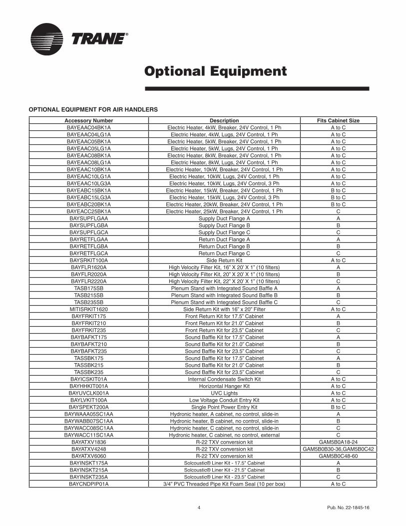
Optional Equipment
OPTIONAL EQUIPMENT FOR AIR HANDLERS
Accessory Number Description Fits Cabinet SizeBAYEAAC04BK1A ElectricHeater,4kW,Breaker,24VControl,1Ph AtoCBAYEAAC04LG1A ElectricHeater,4kW,Lugs,24VControl,1Ph AtoCBAYEAAC05BK1A ElectricHeater,5kW,Breaker,24VControl,1Ph AtoCBAYEAAC05LG1A ElectricHeater,5kW,Lugs,24VControl,1Ph AtoCBAYEAAC08BK1A ElectricHeater,8kW,Breaker,24VControl,1Ph AtoCBAYEAAC08LG1A ElectricHeater,8kW,Lugs,24VControl,1Ph AtoCBAYEAAC10BK1A ElectricHeater,10kW,Breaker,24VControl,1Ph AtoCBAYEAAC10LG1A ElectricHeater,10kW,Lugs,24VControl,1Ph AtoCBAYEAAC10LG3A ElectricHeater,10kW,Lugs,24VControl,3Ph AtoCBAYEABC15BK1A ElectricHeater,15kW,Breaker,24VControl,1Ph BtoCBAYEABC15LG3A ElectricHeater,15kW,Lugs,24VControl,3Ph BtoCBAYEABC20BK1A ElectricHeater,20kW,Breaker,24VControl,1Ph BtoCBAYEACC25BK1A ElectricHeater,25kW,Breaker,24VControl,1Ph CBAYSUPFLGAA SupplyDuctFlangeA ABAYSUPFLGBA SupplyDuctFlangeB BBAYSUPFLGCA SupplyDuctFlangeC CBAYRETFLGAA ReturnDuctFlangeA ABAYRETFLGBA ReturnDuctFlangeB BBAYRETFLGCA ReturnDuctFlangeC CBAYSRKIT100A SideReturnKit AtoCBAYFLR1620A HighVelocityFilterKit,16”X20’X1”(10filters) ABAYFLR2020A HighVelocityFilterKit,20”X20’X1”(10filters) BBAYFLR2220A HighVelocityFilterKit,22”X20’X1”(10filters) C
TASB175SB PlenumStandwithIntegratedSoundBaffleA ATASB215SB PlenumStandwithIntegratedSoundBaffleB BTASB235SB PlenumStandwithIntegratedSoundBaffleC C
MITISRKIT1620 SideReturnKitwith16”x20”Filter AtoCBAYFRKIT175 FrontReturnKitfor17.5”Cabinet ABAYFRKIT210 FrontReturnKitfor21.0”Cabinet BBAYFRKIT235 FrontReturnKitfor23.5”Cabinet CBAYBAFKT175 SoundBaffleKitfor17.5”Cabinet ABAYBAFKT210 SoundBaffleKitfor21.0”Cabinet BBAYBAFKT235 SoundBaffleKitfor23.5”Cabinet C
TASSBK175 SoundBaffleKitfor17.5”Cabinet ATASSBK215 SoundBaffleKitfor21.0”Cabinet BTASSBK235 SoundBaffleKitfor23.5”Cabinet C
BAYICSKIT01A InternalCondensateSwitchKit AtoCBAYHHKIT001A HorizontalHangerKit AtoCBAYUVCLK001A UVCLights AtoCBAYLVKIT100A LowVoltageConduitEntryKit AtoC
BAYSPEKT200A SinglePointPowerEntryKit BtoCBAYWAAA05SC1AA Hydronicheater,Acabinet,nocontrol,slide-in ABAYWABB07SC1AA Hydronicheater,Bcabinet,nocontrol,slide-in BBAYWACC08SC1AA Hydronicheater,Ccabinet,nocontrol,slide-in CBAYWACC11SC1AA Hydronicheater,Ccabinet,nocontrol,external C
BAYATXV1836 R-22TXVconversionkit GAM5B0A18-24BAYATXV4248 R-22TXVconversionkit GAM5B0B30-36,GAM5B0C42BAYATXV6060 R-22TXVconversionkit GAM5B0C48-60
BAYINSKT175A Solcoustic®LinerKit-17.5"Cabinet ABAYINSKT215A Solcoustic®LinerKit-21.5"Cabinet BBAYINSKT235A Solcoustic®LinerKit-23.5"Cabinet CBAYCNDPIP01A 3/4”PVCThreadedPipeKitFoamSeal(10perbox) AtoC
Pub. No. 22-1845-16 5
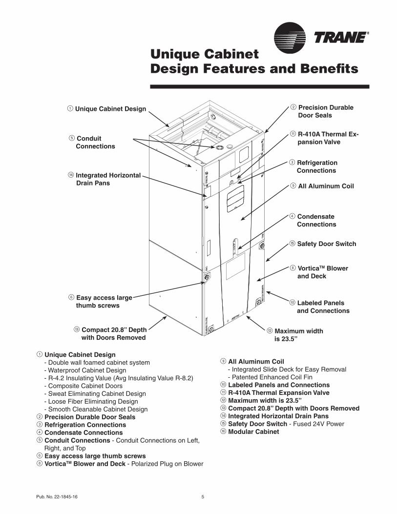
Unique Cabinet Design Features and Benefits
5 Conduit Connections
r Integrated Horizontal Drain Pans
e Compact 20.8” Depth with Doors Removed
2 Precision Durable Door Seals
q R-410A Thermal Ex-pansion Valve
3 Refrigeration Connections
9 All Aluminum Coil
t Safety Door Switch
4 Condensate Connections
w Maximum width is 23.5”
8 VorticaTM Blower and Deck
0 Labeled Panels and Connections
1 Unique Cabinet Design
1 Unique Cabinet Design -Doublewallfoamedcabinetsystem -WaterproofCabinetDesign -R-4.2InsulatingValue(AvgInsulatingValueR-8.2) -CompositeCabinetDoors -SweatEliminatingCabinetDesign -LooseFiberEliminatingDesign -SmoothCleanableCabinetDesign2 Precision Durable Door Seals3 Refrigeration Connections4 Condensate Connections5 Conduit Connections -ConduitConnectionsonLeft,
Right,andTop6 Easy access large thumb screws8 VorticaTM Blower and Deck -PolarizedPlugonBlower
9 All Aluminum Coil -IntegratedSlideDeckforEasyRemoval -PatentedEnhancedCoilFin0 Labeled Panels and Connectionsq R-410A Thermal Expansion Valvew Maximum width is 23.5”e Compact 20.8” Depth with Doors Removedr Integrated Horizontal Drain Panst Safety Door Switch -Fused24VPowery Modular Cabinet
6 Easy access large thumb screws
6 Pub. No. 22-1845-16
GeneralData
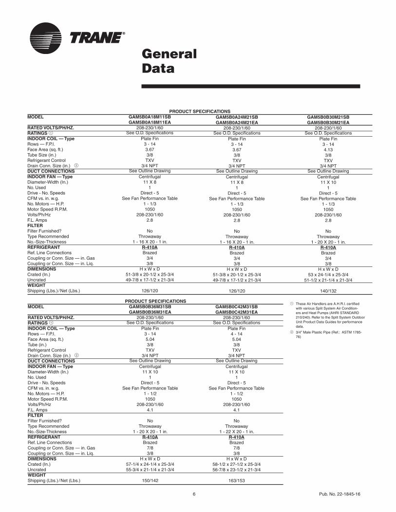
PRODUCT SPECIFICATIONSMODEL GAM5B0A18M11SB GAM5B0A18M11EARATED VOLTS/PH/HZ. 208-230/1/60RATINGS 1 SeeO.D.SpecificationsINDOOR COIL — Type PlateFinRows—F.P.I. 3-14FaceArea(sq.ft.) 3.67TubeSize(in.) 3/8RefrigerantControl TXVDrainConn.Size(in.)2 3/4NPTDUCT CONNECTIONS SeeOutlineDrawingINDOOR FAN — Type CentrifugalDiameter-Width(In.) 11X8No.Used 1Drive-No.Speeds Direct-5CFMvs.in.w.g. SeeFanPerformanceTableNo.Motors—H.P. 1-1/3MotorSpeedR.P.M. 1050Volts/Ph/Hz 208-230/1/60F.L.Amps 2.8FILTERFilterFurnished? NoTypeRecommended ThrowawayNo.-Size-Thickness 1-16X20-1in.REFRIGERANT R-410ARef.LineConnections BrazedCouplingorConn.Size—in.Gas 3/4CouplingorConn.Size—in.Liq. 3/8DIMENSIONS HxWxDCrated(In.) 51-3/8x20-1/2x25-3/4Uncrated 49-7/8x17-1/2x21-3/4WEIGHTShipping(Lbs.)/Net(Lbs.) 126/120
GAM5B0A24M21SBGAM5B0A24M21EA
208-230/1/60SeeO.D.Specifications
PlateFin3-143.673/8TXV
3/4NPTSeeOutlineDrawing
Centrifugal11X8
1Direct-5
SeeFanPerformanceTable1-1/31050
208-230/1/602.8
NoThrowaway
1-16X20-1in.R-410ABrazed
3/43/8
HxWxD51-3/8x20-1/2x25-3/449-7/8x17-1/2x21-3/4
126/120
GAM5B0B30M21SBGAM5B0B30M21EA
208-230/1/60SeeO.D.Specifications
PlateFin3-144.133/8TXV
3/4NPTSeeOutlineDrawing
Centrifugal11X10
1Direct-5
SeeFanPerformanceTable1-1/31050
208-230/1/602.8
NoThrowaway
1-20X20-1in.R-410ABrazed
3/43/8
HxWxD53x24-1/4x25-3/4
51-1/2x21-1/4x21-3/4
140/132
PRODUCT SPECIFICATIONSMODEL GAM5B0B36M31SB GAM5B0B36M31EARATED VOLTS/PH/HZ. 208-230/1/60RATINGS 1 SeeO.D.SpecificationsINDOOR COIL — Type PlateFinRows—F.P.I. 3-14FaceArea(sq.ft.) 5.04Tube(in.) 3/8RefrigerantControl TXVDrainConn.Size(in.)2 3/4NPTDUCT CONNECTIONS SeeOutlineDrawingINDOOR FAN — Type CentrifugalDiameter-Width(In.) 11X10No.Used 1Drive-No.Speeds Direct-5CFMvs.in.w.g. SeeFanPerformanceTableNo.Motors—H.P. 1-1/2MotorSpeedR.P.M. 1050Volts/Ph/Hz 208-230/1/60F.L.Amps 4.1FILTERFilterFurnished? NoTypeRecommended ThrowawayNo.-Size-Thickness 1-20X20-1in.REFRIGERANT R-410ARef.LineConnections BrazedCouplingorConn.Size—in.Gas 7/8CouplingorConn.Size—in.Liq. 3/8DIMENSIONS HxWxDCrated(In.) 57-1/4x24-1/4x25-3/4Uncrated 55-3/4x21-1/4x21-3/4WEIGHTShipping(Lbs.)/Net(Lbs.) 150/142
GAM5B0C42M31SBGAM5B0C42M31EA
208-230/1/60SeeO.D.Specifications
PlateFin4 - 145.043/8TXV
3/4NPTSeeOutlineDrawing
Centrifugal11X10
1Direct-5
SeeFanPerformanceTable1-1/21050
208-230/1/604.1
NoThrowaway
1-22X20-1in.R-410ABrazed
7/83/8
HxWxD58-1/2x27-1/2x25-3/456-7/8x23-1/2x21-3/4
163/153
1 TheseAirHandlersareA.H.R.I.certifiedwithvariousSplitSystemAirCondition-ersandHeatPumps(AHRISTANDARD210/240).RefertotheSplitSystemOutdoorUnitProductDataGuidesforperformancedata.
2 3/4"MalePlasticPipe(Ref.:ASTM1785-76)
Pub.No.22-1845-16 7
GeneralData
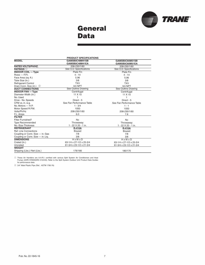
1 These Air Handlers are A.H.R.I. certified with various Split System Air Conditioners and HeatPumps(AHRISTANDARD210/240).RefertotheSplitSystemOutdoorUnitProductDataGuidesforperformancedata.
2 3/4"MalePlasticPipe(Ref.:ASTM1785-76)
PRODUCT SPECIFICATIONSMODEL GAM5B0C48M41SB GAM5B0C48M41EARATED VOLTS/PH/HZ. 208-230/1/60RATINGS 1 SeeO.D.SpecificationsINDOOR COIL — Type PlateFinRows—F.P.I. 4-14FaceArea(sq.ft.) 5.96TubeSize(in.) 3/8RefrigerantControl TXVDrainConn.Size(in.)2 3/4NPTDUCT CONNECTIONS SeeOutlineDrawingINDOOR FAN — Type CentrifugalDiameter-Width(In.) 11X10No.Used 1Drive-No.Speeds Direct-5CFMvs.in.w.g. SeeFanPerformanceTableNo.Motors—H.P. 1-3/4MotorSpeedR.P.M. 1050Volts/Ph/Hz 208-230/1/60F.L.Amps 6.0FILTERFilterFurnished? NoTypeRecommended ThrowawayNo.-Size-Thickness 1-22X20-1in.REFRIGERANT R-410ARef.LineConnections BrazedCouplingorConn.Size—in.Gas 7/8CouplingorConn.Size—in.Liq. 3/8DIMENSIONS HxWxDCrated(In.) 63-1/4x27-1/2x25-3/4Uncrated 61-3/4x23-1/2x21-3/4WEIGHTShipping(Lbs.)/Net(Lbs.) 176/166
GAM5B0C60M51SBGAM5B0C60M51EA
208-230/1/60SeeO.D.Specifications
PlateFin4 - 145.963/8TXV
3/4NPTSeeOutlineDrawing
Centrifugal11X10
1Direct-5
SeeFanPerformanceTable1 - 11050
208-230/1/607.6
NoThrowaway
1-22X20-1in.R-410ABrazed
7/83/8
HxWxD63-1/4x27-1/2x25-3/461-3/4x23-1/2x21-3/4
180/170
8 Pub. No. 22-1845-16
PerformanceData
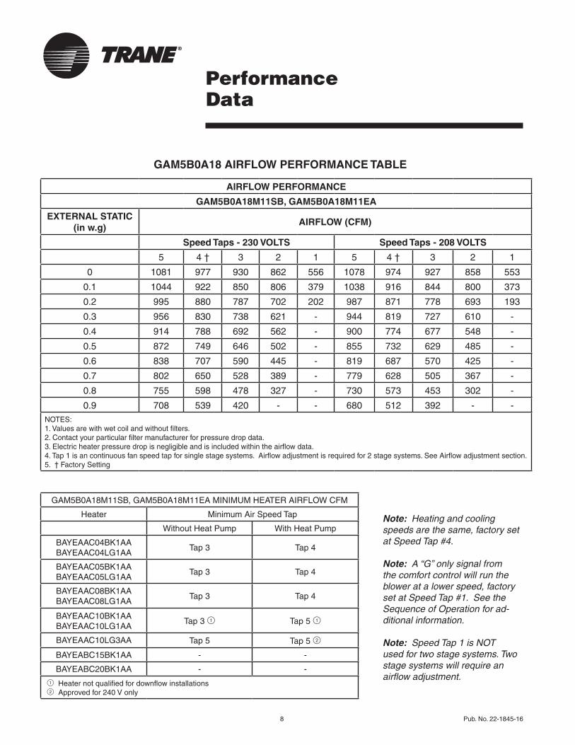
GAM5B0A18 AIRFLOW PERFORMANCE TABLE
Note: Heating and cooling speeds are the same, factory set at Speed Tap #4.
Note: A “G” only signal from the comfort control will run the blower at a lower speed, factory set at Speed Tap #1. See the Sequence of Operation for ad-ditional information.
Note: Speed Tap 1 is NOT used for two stage systems. Two stage systems will require an airflow adjustment.
AIRFLOW PERFORMANCE
GAM5B0A18M11SB, GAM5B0A18M11EA
EXTERNAL STATIC (in w.g)
AIRFLOW (CFM)
Speed Taps - 230 VOLTS Speed Taps - 208 VOLTS
5 4 † 3 2 1 5 4 † 3 2 1
0 1081 977 930 862 556 1078 974 927 858 553
0.1 1044 922 850 806 379 1038 916 844 800 373
0.2 995 880 787 702 202 987 871 778 693 193
0.3 956 830 738 621 - 944 819 727 610 -
0.4 914 788 692 562 - 900 774 677 548 -
0.5 872 749 646 502 - 855 732 629 485 -
0.6 838 707 590 445 - 819 687 570 425 -
0.7 802 650 528 389 - 779 628 505 367 -
0.8 755 598 478 327 - 730 573 453 302 -
0.9 708 539 420 - - 680 512 392 - -NOTES:1.Valuesarewithwetcoilandwithoutfilters.2.Contactyourparticularfiltermanufacturerforpressuredropdata. 3.Electricheaterpressuredropisnegligibleandisincludedwithintheairflowdata.4.Tap1isancontinuousfanspeedtapforsinglestagesystems.Airflowadjustmentisrequiredfor2stagesystems.SeeAirflowadjustmentsection.5. †FactorySetting
GAM5B0A18M11SB,GAM5B0A18M11EAMINIMUMHEATERAIRFLOWCFM
Heater MinimumAirSpeedTap
WithoutHeatPump WithHeatPump
BAYEAAC04BK1AABAYEAAC04LG1AA
Tap3 Tap4
BAYEAAC05BK1AABAYEAAC05LG1AA
Tap3 Tap4
BAYEAAC08BK1AA BAYEAAC08LG1AA
Tap3 Tap4
BAYEAAC10BK1AABAYEAAC10LG1AA
Tap3 1 Tap5 1
BAYEAAC10LG3AA Tap5 Tap5 2
BAYEABC15BK1AA - -
BAYEABC20BK1AA - -
1Heaternotqualifiedfordownflowinstallations 2Approvedfor240Vonly
Pub.No.22-1845-16 9
PerformanceData
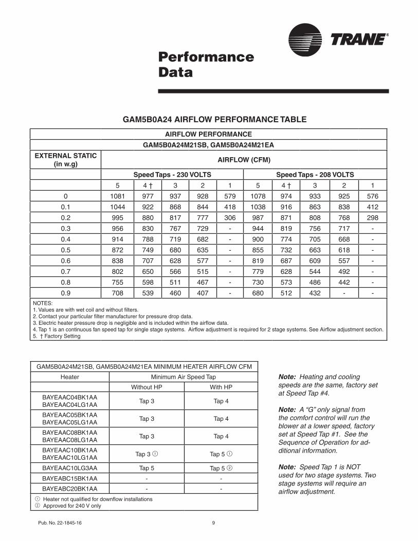
GAM5B0A24 AIRFLOW PERFORMANCE TABLE
Note: Heating and cooling speeds are the same, factory set at Speed Tap #4.
Note: A “G” only signal from the comfort control will run the blower at a lower speed, factory set at Speed Tap #1. See the Sequence of Operation for ad-ditional information.
Note: Speed Tap 1 is NOT used for two stage systems. Two stage systems will require an airflow adjustment.
AIRFLOW PERFORMANCE
GAM5B0A24M21SB, GAM5B0A24M21EA
EXTERNAL STATIC (in w.g)
AIRFLOW (CFM)
Speed Taps - 230 VOLTS Speed Taps - 208 VOLTS
5 4 † 3 2 1 5 4 † 3 2 1
0 1081 977 937 928 579 1078 974 933 925 576
0.1 1044 922 868 844 418 1038 916 863 838 412
0.2 995 880 817 777 306 987 871 808 768 298
0.3 956 830 767 729 - 944 819 756 717 -
0.4 914 788 719 682 - 900 774 705 668 -
0.5 872 749 680 635 - 855 732 663 618 -
0.6 838 707 628 577 - 819 687 609 557 -
0.7 802 650 566 515 - 779 628 544 492 -
0.8 755 598 511 467 - 730 573 486 442 -
0.9 708 539 460 407 - 680 512 432 - -NOTES:1.Valuesarewithwetcoilandwithoutfilters.2.Contactyourparticularfiltermanufacturerforpressuredropdata. 3.Electricheaterpressuredropisnegligibleandisincludedwithintheairflowdata.4.Tap1isancontinuousfanspeedtapforsinglestagesystems.Airflowadjustmentisrequiredfor2stagesystems.SeeAirflowadjustmentsection.5. †FactorySetting
GAM5B0A24M21SB,GAM5B0A24M21EAMINIMUMHEATERAIRFLOWCFM
Heater MinimumAirSpeedTap
WithoutHP WithHP
BAYEAAC04BK1AABAYEAAC04LG1AA
Tap3 Tap4
BAYEAAC05BK1AABAYEAAC05LG1AA
Tap3 Tap4
BAYEAAC08BK1AA BAYEAAC08LG1AA
Tap3 Tap4
BAYEAAC10BK1AA BAYEAAC10LG1AA Tap3 1 Tap5 1
BAYEAAC10LG3AA Tap5 Tap5 2
BAYEABC15BK1AA - -
BAYEABC20BK1AA - -
1Heaternotqualifiedfordownflowinstallations 2Approvedfor240Vonly
10 Pub. No. 22-1845-16
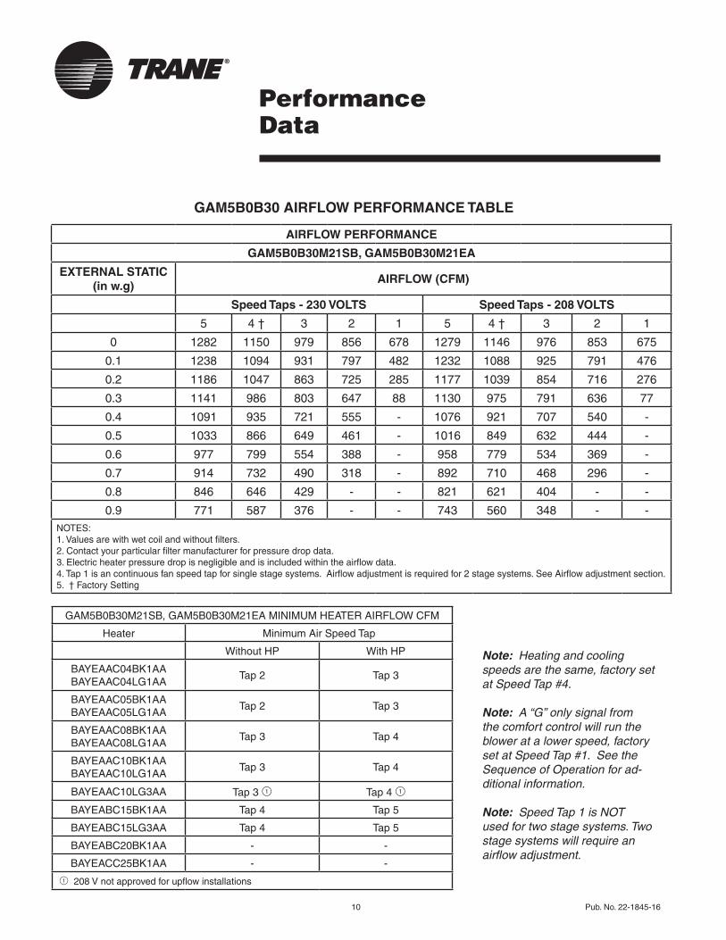
GAM5B0B30 AIRFLOW PERFORMANCE TABLE
PerformanceData
Note: Heating and cooling speeds are the same, factory set at Speed Tap #4.
Note: A “G” only signal from the comfort control will run the blower at a lower speed, factory set at Speed Tap #1. See the Sequence of Operation for ad-ditional information.
Note: Speed Tap 1 is NOT used for two stage systems. Two stage systems will require an airflow adjustment.
AIRFLOW PERFORMANCE
GAM5B0B30M21SB, GAM5B0B30M21EA
EXTERNAL STATIC (in w.g)
AIRFLOW (CFM)
Speed Taps - 230 VOLTS Speed Taps - 208 VOLTS
5 4 † 3 2 1 5 4 † 3 2 1
0 1282 1150 979 856 678 1279 1146 976 853 675
0.1 1238 1094 931 797 482 1232 1088 925 791 476
0.2 1186 1047 863 725 285 1177 1039 854 716 276
0.3 1141 986 803 647 88 1130 975 791 636 77
0.4 1091 935 721 555 - 1076 921 707 540 -
0.5 1033 866 649 461 - 1016 849 632 444 -
0.6 977 799 554 388 - 958 779 534 369 -
0.7 914 732 490 318 - 892 710 468 296 -
0.8 846 646 429 - - 821 621 404 - -
0.9 771 587 376 - - 743 560 348 - -NOTES:1.Valuesarewithwetcoilandwithoutfilters.2.Contactyourparticularfiltermanufacturerforpressuredropdata. 3.Electricheaterpressuredropisnegligibleandisincludedwithintheairflowdata.4.Tap1isancontinuousfanspeedtapforsinglestagesystems.Airflowadjustmentisrequiredfor2stagesystems.SeeAirflowadjustmentsection.5. †FactorySetting
GAM5B0B30M21SB,GAM5B0B30M21EAMINIMUMHEATERAIRFLOWCFM
Heater MinimumAirSpeedTap
WithoutHP WithHP
BAYEAAC04BK1AABAYEAAC04LG1AA
Tap2 Tap3
BAYEAAC05BK1AABAYEAAC05LG1AA
Tap2 Tap3
BAYEAAC08BK1AA BAYEAAC08LG1AA
Tap3 Tap4
BAYEAAC10BK1AA BAYEAAC10LG1AA
Tap3 Tap4
BAYEAAC10LG3AA Tap3 1 Tap4 1
BAYEABC15BK1AA Tap4 Tap5
BAYEABC15LG3AA Tap4 Tap5
BAYEABC20BK1AA - -
BAYEACC25BK1AA - -
1208Vnotapprovedforupflowinstallations
Pub. No. 22-1845-16 11
PerformanceData
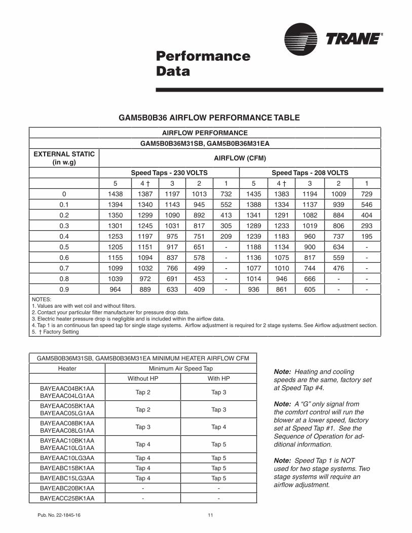
GAM5B0B36 AIRFLOW PERFORMANCE TABLE
Note: Heating and cooling speeds are the same, factory set at Speed Tap #4.
Note: A “G” only signal from the comfort control will run the blower at a lower speed, factory set at Speed Tap #1. See the Sequence of Operation for ad-ditional information.
Note: Speed Tap 1 is NOT used for two stage systems. Two stage systems will require an airflow adjustment.
AIRFLOW PERFORMANCE
GAM5B0B36M31SB, GAM5B0B36M31EA
EXTERNAL STATIC (in w.g)
AIRFLOW (CFM)
Speed Taps - 230 VOLTS Speed Taps - 208 VOLTS
5 4 † 3 2 1 5 4 † 3 2 1
0 1438 1387 1197 1013 732 1435 1383 1194 1009 729
0.1 1394 1340 1143 945 552 1388 1334 1137 939 546
0.2 1350 1299 1090 892 413 1341 1291 1082 884 404
0.3 1301 1245 1031 817 305 1289 1233 1019 806 293
0.4 1253 1197 975 751 209 1239 1183 960 737 195
0.5 1205 1151 917 651 - 1188 1134 900 634 -
0.6 1155 1094 837 578 - 1136 1075 817 559 -
0.7 1099 1032 766 499 - 1077 1010 744 476 -
0.8 1039 972 691 453 - 1014 946 666 - -
0.9 964 889 633 409 - 936 861 605 - -NOTES:1.Valuesarewithwetcoilandwithoutfilters.2.Contactyourparticularfiltermanufacturerforpressuredropdata. 3.Electricheaterpressuredropisnegligibleandisincludedwithintheairflowdata.4.Tap1isancontinuousfanspeedtapforsinglestagesystems.Airflowadjustmentisrequiredfor2stagesystems.SeeAirflowadjustmentsection.5. †FactorySetting
GAM5B0B36M31SB,GAM5B0B36M31EAMINIMUMHEATERAIRFLOWCFM
Heater MinimumAirSpeedTap
WithoutHP WithHP
BAYEAAC04BK1AABAYEAAC04LG1AA
Tap2 Tap3
BAYEAAC05BK1AABAYEAAC05LG1AA
Tap2 Tap3
BAYEAAC08BK1AA BAYEAAC08LG1AA
Tap3 Tap4
BAYEAAC10BK1AA BAYEAAC10LG1AA
Tap4 Tap5
BAYEAAC10LG3AA Tap4 Tap5
BAYEABC15BK1AA Tap4 Tap5
BAYEABC15LG3AA Tap4 Tap5
BAYEABC20BK1AA - -
BAYEACC25BK1AA - -
12 Pub. No. 22-1845-16
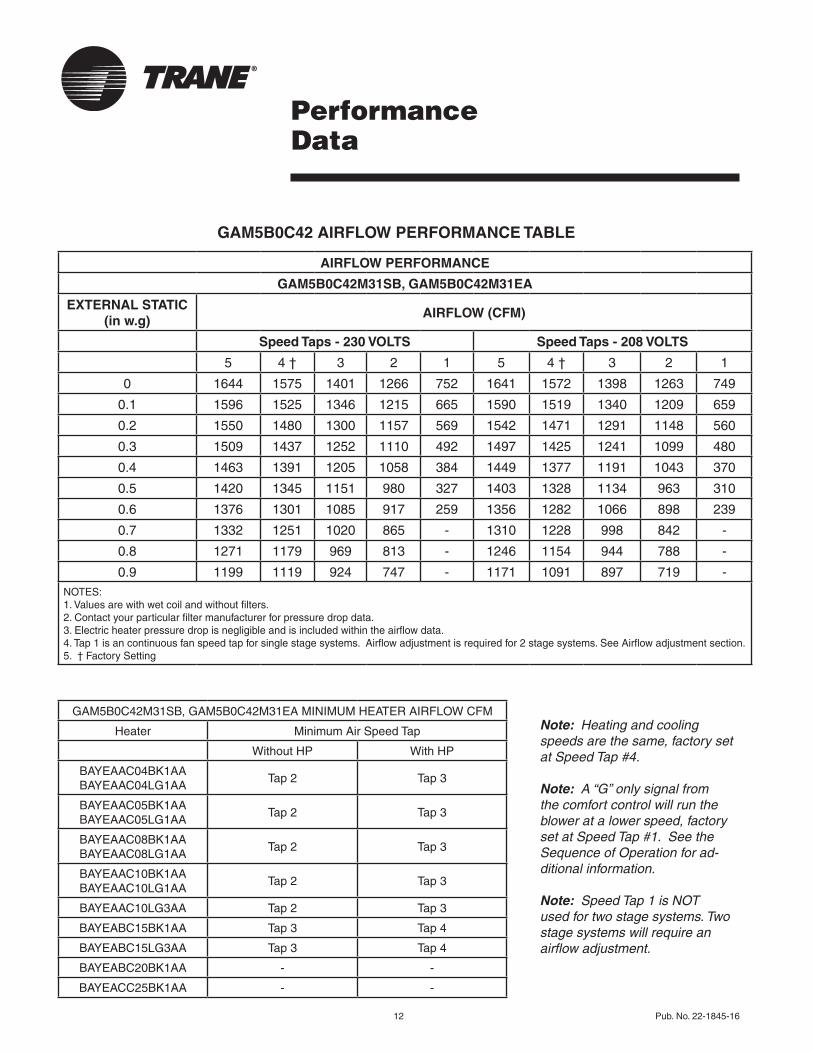
GAM5B0C42 AIRFLOW PERFORMANCE TABLE
PerformanceData
Note: Heating and cooling speeds are the same, factory set at Speed Tap #4.
Note: A “G” only signal from the comfort control will run the blower at a lower speed, factory set at Speed Tap #1. See the Sequence of Operation for ad-ditional information.
Note: Speed Tap 1 is NOT used for two stage systems. Two stage systems will require an airflow adjustment.
AIRFLOW PERFORMANCE
GAM5B0C42M31SB, GAM5B0C42M31EA
EXTERNAL STATIC (in w.g)
AIRFLOW (CFM)
Speed Taps - 230 VOLTS Speed Taps - 208 VOLTS
5 4 † 3 2 1 5 4 † 3 2 1
0 1644 1575 1401 1266 752 1641 1572 1398 1263 749
0.1 1596 1525 1346 1215 665 1590 1519 1340 1209 659
0.2 1550 1480 1300 1157 569 1542 1471 1291 1148 560
0.3 1509 1437 1252 1110 492 1497 1425 1241 1099 480
0.4 1463 1391 1205 1058 384 1449 1377 1191 1043 370
0.5 1420 1345 1151 980 327 1403 1328 1134 963 310
0.6 1376 1301 1085 917 259 1356 1282 1066 898 239
0.7 1332 1251 1020 865 - 1310 1228 998 842 -
0.8 1271 1179 969 813 - 1246 1154 944 788 -
0.9 1199 1119 924 747 - 1171 1091 897 719 -NOTES:1.Valuesarewithwetcoilandwithoutfilters.2.Contactyourparticularfiltermanufacturerforpressuredropdata. 3.Electricheaterpressuredropisnegligibleandisincludedwithintheairflowdata.4.Tap1isancontinuousfanspeedtapforsinglestagesystems.Airflowadjustmentisrequiredfor2stagesystems.SeeAirflowadjustmentsection.5. †FactorySetting
GAM5B0C42M31SB,GAM5B0C42M31EAMINIMUMHEATERAIRFLOWCFM
Heater MinimumAirSpeedTap
WithoutHP WithHP
BAYEAAC04BK1AABAYEAAC04LG1AA
Tap2 Tap3
BAYEAAC05BK1AABAYEAAC05LG1AA
Tap2 Tap3
BAYEAAC08BK1AA BAYEAAC08LG1AA
Tap2 Tap3
BAYEAAC10BK1AA BAYEAAC10LG1AA
Tap2 Tap3
BAYEAAC10LG3AA Tap2 Tap3
BAYEABC15BK1AA Tap3 Tap4
BAYEABC15LG3AA Tap3 Tap4
BAYEABC20BK1AA - -
BAYEACC25BK1AA - -
Pub.No.22-1845-16 13
PerformanceData
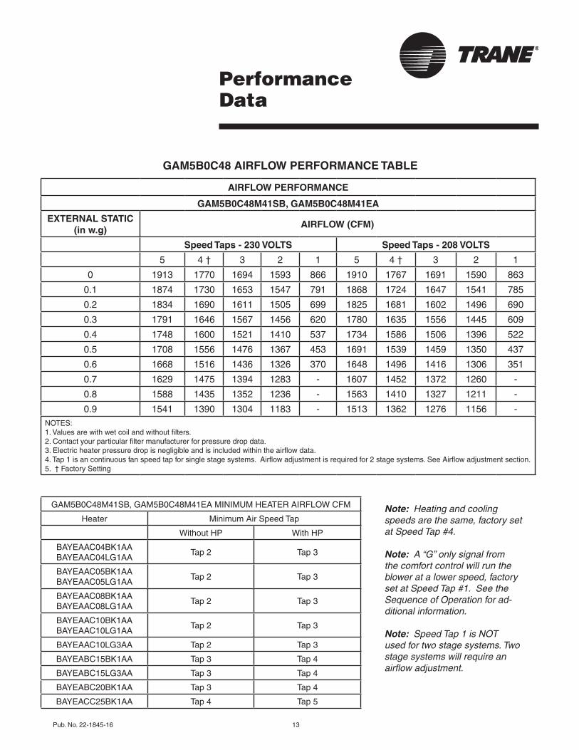
GAM5B0C48 AIRFLOW PERFORMANCE TABLE
Note: Heating and cooling speeds are the same, factory set at Speed Tap #4.
Note: A “G” only signal from the comfort control will run the blower at a lower speed, factory set at Speed Tap #1. See the Sequence of Operation for ad-ditional information.
Note: Speed Tap 1 is NOT used for two stage systems. Two stage systems will require an airflow adjustment.
AIRFLOW PERFORMANCE
GAM5B0C48M41SB, GAM5B0C48M41EA
EXTERNAL STATIC (in w.g)
AIRFLOW (CFM)
Speed Taps - 230 VOLTS Speed Taps - 208 VOLTS
5 4 † 3 2 1 5 4 † 3 2 1
0 1913 1770 1694 1593 866 1910 1767 1691 1590 863
0.1 1874 1730 1653 1547 791 1868 1724 1647 1541 785
0.2 1834 1690 1611 1505 699 1825 1681 1602 1496 690
0.3 1791 1646 1567 1456 620 1780 1635 1556 1445 609
0.4 1748 1600 1521 1410 537 1734 1586 1506 1396 522
0.5 1708 1556 1476 1367 453 1691 1539 1459 1350 437
0.6 1668 1516 1436 1326 370 1648 1496 1416 1306 351
0.7 1629 1475 1394 1283 - 1607 1452 1372 1260 -
0.8 1588 1435 1352 1236 - 1563 1410 1327 1211 -
0.9 1541 1390 1304 1183 - 1513 1362 1276 1156 -NOTES:1.Valuesarewithwetcoilandwithoutfilters.2.Contactyourparticularfiltermanufacturerforpressuredropdata. 3.Electricheaterpressuredropisnegligibleandisincludedwithintheairflowdata.4.Tap1isancontinuousfanspeedtapforsinglestagesystems.Airflowadjustmentisrequiredfor2stagesystems.SeeAirflowadjustmentsection.5. †FactorySetting
GAM5B0C48M41SB,GAM5B0C48M41EAMINIMUMHEATERAIRFLOWCFM
Heater MinimumAirSpeedTap
WithoutHP WithHP
BAYEAAC04BK1AABAYEAAC04LG1AA
Tap2 Tap3
BAYEAAC05BK1AABAYEAAC05LG1AA
Tap2 Tap3
BAYEAAC08BK1AA BAYEAAC08LG1AA
Tap2 Tap3
BAYEAAC10BK1AA BAYEAAC10LG1AA
Tap2 Tap3
BAYEAAC10LG3AA Tap2 Tap3
BAYEABC15BK1AA Tap3 Tap4
BAYEABC15LG3AA Tap3 Tap4
BAYEABC20BK1AA Tap3 Tap4
BAYEACC25BK1AA Tap4 Tap5
14 Pub. No. 22-1845-16
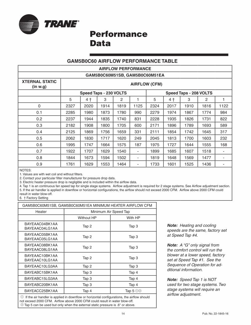
GAM5B0C60 AIRFLOW PERFORMANCE TABLE
PerformanceData
Note: Heating and cooling speeds are the same, factory set at Speed Tap #4.
Note: A “G” only signal from the comfort control will run the blower at a lower speed, factory set at Speed Tap #1. See the Sequence of Operation for ad-ditional information.
Note: Speed Tap 1 is NOT used for two stage systems. Two stage systems will require an airflow adjustment.
AIRFLOW PERFORMANCE
GAM5B0C60M51SB, GAM5B0C60M51EA
XTERNAL STATIC (in w.g)
AIRFLOW (CFM)
Speed Taps - 230 VOLTS Speed Taps - 208 VOLTS
5 4 † 3 2 1 5 4 † 3 2 1
0 2327 2020 1914 1819 1125 2324 2017 1910 1816 1122
0.1 2285 1980 1873 1780 990 2279 1974 1867 1774 984
0.2 2237 1944 1835 1740 831 2228 1935 1826 1731 822
0.3 2182 1908 1800 1705 600 2171 1896 1789 1693 589
0.4 2125 1869 1756 1659 331 2111 1854 1742 1645 317
0.5 2062 1830 1717 1620 249 2045 1813 1700 1603 232
0.6 1995 1747 1664 1575 187 1975 1727 1644 1555 168
0.7 1922 1707 1629 1540 - 1899 1685 1607 1518 -
0.8 1844 1673 1594 1502 - 1819 1648 1569 1477 -
0.9 1761 1629 1553 1464 - 1733 1601 1525 1436 -NOTES:1.Valuesarewithwetcoilandwithoutfilters.2.Contactyourparticularfiltermanufacturerforpressuredropdata. 3.Electricheaterpressuredropisnegligibleandisincludedwithintheairflowdata.4.Tap1isancontinuousfanspeedtapforsinglestagesystems.Airflowadjustmentisrequiredfor2stagesystems.SeeAirflowadjustmentsection.5.Iftheairhandlerisappliedindownfloworhorizontalconfigurations,theairflowshouldnotexceed2000CFM.Airflowabove2000CFMcouldresultinwaterblow-off.6. †FactorySetting
GAM5B0C60M51SB,GAM5B0C60M51EAMINIMUMHEATERAIRFLOWCFM
Heater MinimumAirSpeedTap
WithoutHP WithHP
BAYEAAC04BK1AABAYEAAC04LG1AA
Tap2 Tap3
BAYEAAC05BK1AABAYEAAC05LG1AA
Tap2 Tap3
BAYEAAC08BK1AA BAYEAAC08LG1AA
Tap2 Tap3
BAYEAAC10BK1AA BAYEAAC10LG1AA
Tap2 Tap3
BAYEAAC10LG3AA Tap2 Tap3
BAYEABC15BK1AA Tap3 Tap4
BAYEABC15LG3AA Tap3 Tap4
BAYEABC20BK1AA Tap3 Tap4
BAYEACC25BK1AA Tap4 Tap5 12
1Iftheairhandlerisappliedindownfloworhorizontalconfigurations,theairflowshouldnotexceed2000CFM.Airflowabove2000CFMcouldresultinwaterblow-off. 2Tap5canbeusedbutonlywhentheexternalstaticpressureis.6"orabove.
Pub. No. 22-1845-16 15
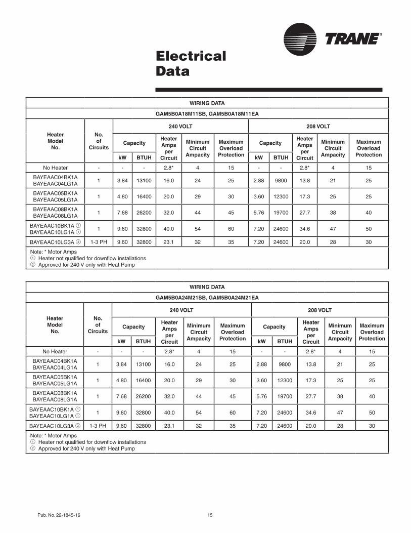
ElectricalData
WIRING DATA
GAM5B0A18M11SB, GAM5B0A18M11EA
Heater Model
No.
No. of
Circuits
240 VOLT 208 VOLT
CapacityHeater Amps
per Circuit
Minimum Circuit
Ampacity
Maximum Overload
Protection
CapacityHeater Amps
per Circuit
Minimum Circuit
Ampacity
Maximum Overload
ProtectionkW BTUH kW BTUH
NoHeater - - - 2.8* 4 15 - - 2.8* 4 15
BAYEAAC04BK1ABAYEAAC04LG1A
1 3.84 13100 16.0 24 25 2.88 9800 13.8 21 25
BAYEAAC05BK1ABAYEAAC05LG1A
1 4.80 16400 20.0 29 30 3.60 12300 17.3 25 25
BAYEAAC08BK1ABAYEAAC08LG1A
1 7.68 26200 32.0 44 45 5.76 19700 27.7 38 40
BAYEAAC10BK1A 1BAYEAAC10LG1A 1
1 9.60 32800 40.0 54 60 7.20 24600 34.6 47 50
BAYEAAC10LG3A 2 1-3PH 9.60 32800 23.1 32 35 7.20 24600 20.0 28 30
Note:*MotorAmps 1Heaternotqualifiedfordownflowinstallations 2Approvedfor240VonlywithHeatPump
WIRING DATA
GAM5B0A24M21SB, GAM5B0A24M21EA
Heater Model
No.
No. of
Circuits
240 VOLT 208 VOLT
CapacityHeater Amps
per Circuit
Minimum Circuit
Ampacity
Maximum Overload
Protection
CapacityHeater Amps
per Circuit
Minimum Circuit
Ampacity
Maximum Overload
ProtectionkW BTUH kW BTUH
NoHeater - - - 2.8* 4 15 - - 2.8* 4 15
BAYEAAC04BK1ABAYEAAC04LG1A
1 3.84 13100 16.0 24 25 2.88 9800 13.8 21 25
BAYEAAC05BK1ABAYEAAC05LG1A
1 4.80 16400 20.0 29 30 3.60 12300 17.3 25 25
BAYEAAC08BK1ABAYEAAC08LG1A
1 7.68 26200 32.0 44 45 5.76 19700 27.7 38 40
BAYEAAC10BK1A 1BAYEAAC10LG1A 1
1 9.60 32800 40.0 54 60 7.20 24600 34.6 47 50
BAYEAAC10LG3A 2 1-3PH 9.60 32800 23.1 32 35 7.20 24600 20.0 28 30
Note:*MotorAmps 1Heaternotqualifiedfordownflowinstallations 2Approvedfor240VonlywithHeatPump
16 Pub. No. 22-1845-16
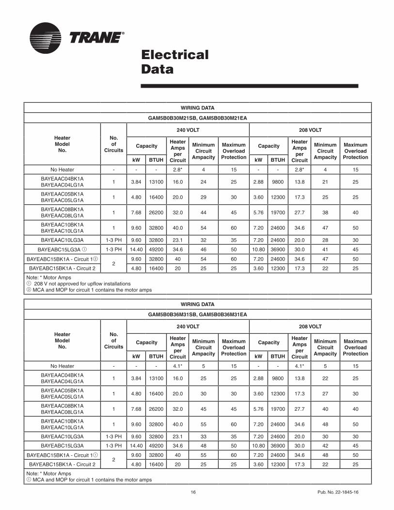
ElectricalData
WIRING DATA
GAM5B0B30M21SB, GAM5B0B30M21EA
Heater Model
No.
No. of
Circuits
240 VOLT 208 VOLT
CapacityHeater Amps
per Circuit
Minimum Circuit
Ampacity
Maximum Overload
Protection
CapacityHeater Amps
per Circuit
Minimum Circuit
Ampacity
Maximum Overload
ProtectionkW BTUH kW BTUH
NoHeater - - - 2.8* 4 15 - - 2.8* 4 15
BAYEAAC04BK1ABAYEAAC04LG1A
1 3.84 13100 16.0 24 25 2.88 9800 13.8 21 25
BAYEAAC05BK1ABAYEAAC05LG1A
1 4.80 16400 20.0 29 30 3.60 12300 17.3 25 25
BAYEAAC08BK1ABAYEAAC08LG1A
1 7.68 26200 32.0 44 45 5.76 19700 27.7 38 40
BAYEAAC10BK1ABAYEAAC10LG1A
1 9.60 32800 40.0 54 60 7.20 24600 34.6 47 50
BAYEAAC10LG3A 1-3PH 9.60 32800 23.1 32 35 7.20 24600 20.0 28 30
BAYEABC15LG3A1 1-3PH 14.40 49200 34.6 46 50 10.80 36900 30.0 41 45
BAYEABC15BK1A-Circuit122
9.60 32800 40 54 60 7.20 24600 34.6 47 50
BAYEABC15BK1A-Circuit2 4.80 16400 20 25 25 3.60 12300 17.3 22 25
Note:*MotorAmps1208Vnotapprovedforupflowinstallations2 MCAandMOPforcircuit1containsthemotoramps
WIRING DATA
GAM5B0B36M31SB, GAM5B0B36M31EA
Heater Model
No.
No. of
Circuits
240 VOLT 208 VOLT
CapacityHeater Amps
per Circuit
Minimum Circuit
Ampacity
Maximum Overload
Protection
CapacityHeater Amps
per Circuit
Minimum Circuit
Ampacity
Maximum Overload
ProtectionkW BTUH kW BTUH
NoHeater - - - 4.1* 5 15 - - 4.1* 5 15
BAYEAAC04BK1ABAYEAAC04LG1A
1 3.84 13100 16.0 25 25 2.88 9800 13.8 22 25
BAYEAAC05BK1ABAYEAAC05LG1A
1 4.80 16400 20.0 30 30 3.60 12300 17.3 27 30
BAYEAAC08BK1ABAYEAAC08LG1A
1 7.68 26200 32.0 45 45 5.76 19700 27.7 40 40
BAYEAAC10BK1ABAYEAAC10LG1A
1 9.60 32800 40.0 55 60 7.20 24600 34.6 48 50
BAYEAAC10LG3A 1-3PH 9.60 32800 23.1 33 35 7.20 24600 20.0 30 30
BAYEABC15LG3A 1-3PH 14.40 49200 34.6 48 50 10.80 36900 30.0 42 45
BAYEABC15BK1A-Circuit112
9.60 32800 40 55 60 7.20 24600 34.6 48 50
BAYEABC15BK1A-Circuit2 4.80 16400 20 25 25 3.60 12300 17.3 22 25
Note:*MotorAmps1 MCAandMOPforcircuit1containsthemotoramps
Pub.No.22-1845-16 17
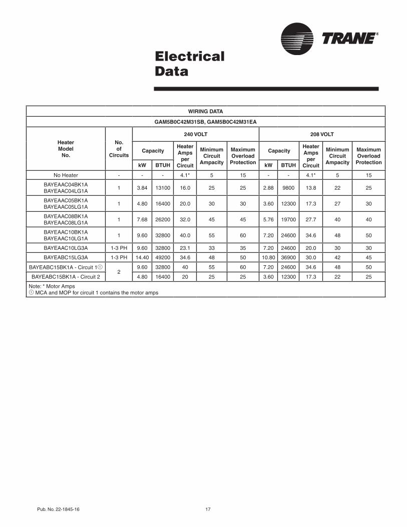
ElectricalData
WIRING DATA
GAM5B0C42M31SB, GAM5B0C42M31EA
Heater Model
No.
No. of
Circuits
240 VOLT 208 VOLT
CapacityHeater Amps
per Circuit
Minimum Circuit
Ampacity
Maximum Overload
Protection
CapacityHeater Amps
per Circuit
Minimum Circuit
Ampacity
Maximum Overload
ProtectionkW BTUH kW BTUH
NoHeater - - - 4.1* 5 15 - - 4.1* 5 15
BAYEAAC04BK1ABAYEAAC04LG1A
1 3.84 13100 16.0 25 25 2.88 9800 13.8 22 25
BAYEAAC05BK1ABAYEAAC05LG1A
1 4.80 16400 20.0 30 30 3.60 12300 17.3 27 30
BAYEAAC08BK1ABAYEAAC08LG1A
1 7.68 26200 32.0 45 45 5.76 19700 27.7 40 40
BAYEAAC10BK1ABAYEAAC10LG1A
1 9.60 32800 40.0 55 60 7.20 24600 34.6 48 50
BAYEAAC10LG3A 1-3PH 9.60 32800 23.1 33 35 7.20 24600 20.0 30 30
BAYEABC15LG3A 1-3PH 14.40 49200 34.6 48 50 10.80 36900 30.0 42 45
BAYEABC15BK1A-Circuit112
9.60 32800 40 55 60 7.20 24600 34.6 48 50
BAYEABC15BK1A-Circuit2 4.80 16400 20 25 25 3.60 12300 17.3 22 25
Note:*MotorAmps1 MCAandMOPforcircuit1containsthemotoramps
18 Pub. No. 22-1845-16
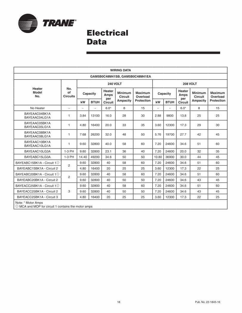
ElectricalData
WIRING DATA
GAM5B0C48M41SB, GAM5B0C48M41EA
Heater Model
No.
No. of
Circuits
240 VOLT 208 VOLT
CapacityHeater Amps
per Circuit
Minimum Circuit
Ampacity
Maximum Overload
Protection
CapacityHeater Amps
per Circuit
Minimum Circuit
Ampacity
Maximum Overload
ProtectionkW BTUH kW BTUH
NoHeater - - - 6.0* 8 15 - - 6.0* 8 15
BAYEAAC04BK1ABAYEAAC04LG1A
1 3.84 13100 16.0 28 30 2.88 9800 13.8 25 25
BAYEAAC05BK1ABAYEAAC05LG1A
1 4.80 16400 20.0 33 35 3.60 12300 17.3 29 30
BAYEAAC08BK1ABAYEAAC08LG1A
1 7.68 26200 32.0 48 50 5.76 19700 27.7 42 45
BAYEAAC10BK1ABAYEAAC10LG1A
1 9.60 32800 40.0 58 60 7.20 24600 34.6 51 60
BAYEAAC10LG3A 1-3PH 9.60 32800 23.1 36 40 7.20 24600 20.0 32 35
BAYEABC15LG3A 1-3PH 14.40 49200 34.6 50 50 10.80 36900 30.0 44 45
BAYEABC15BK1A-Circuit112
9.60 32800 40 58 60 7.20 24600 34.6 51 60
BAYEABC15BK1A-Circuit2 4.80 16400 20 25 25 3.60 12300 17.3 22 25
BAYEABC20BK1A-Circuit112
9.60 32800 40 58 60 7.20 24600 34.6 51 60
BAYEABC20BK1A-Circuit2 9.60 32800 40 50 50 7.20 24600 34.6 43 45
BAYEACC25BK1A-Circuit11
3
9.60 32800 40 58 60 7.20 24600 34.6 51 60
BAYEACC25BK1A-Circuit2 9.60 32800 40 50 50 7.20 24600 34.6 43 45
BAYEACC25BK1A-Circuit3 4.80 16400 20 25 25 3.60 12300 17.3 22 25
Note:*MotorAmps1 MCAandMOPforcircuit1containsthemotoramps
Pub.No.22-1845-16 19
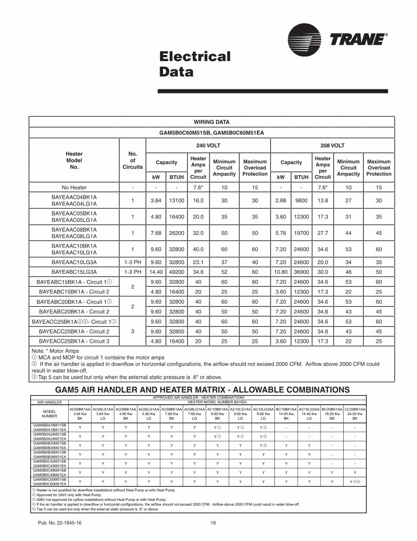
ElectricalData
GAM5 AIR HANDLER AND HEATER MATRIX - ALLOWABLE COMBINATIONS
WIRING DATA
GAM5B0C60M51SB, GAM5B0C60M51EA
Heater Model
No.
No. of
Circuits
240 VOLT 208 VOLT
CapacityHeater Amps
per Circuit
Minimum Circuit
Ampacity
Maximum Overload
Protection
CapacityHeater Amps
per Circuit
Minimum Circuit
Ampacity
Maximum Overload
ProtectionkW BTUH kW BTUH
NoHeater - - - 7.6* 10 15 - - 7.6* 10 15
BAYEAAC04BK1ABAYEAAC04LG1A
1 3.84 13100 16.0 30 30 2.88 9800 13.8 27 30
BAYEAAC05BK1ABAYEAAC05LG1A
1 4.80 16400 20.0 35 35 3.60 12300 17.3 31 35
BAYEAAC08BK1ABAYEAAC08LG1A
1 7.68 26200 32.0 50 50 5.76 19700 27.7 44 45
BAYEAAC10BK1ABAYEAAC10LG1A
1 9.60 32800 40.0 60 60 7.20 24600 34.6 53 60
BAYEAAC10LG3A 1-3PH 9.60 32800 23.1 37 40 7.20 24600 20.0 34 35
BAYEABC15LG3A 1-3PH 14.40 49200 34.6 52 60 10.80 36900 30.0 46 50
BAYEABC15BK1A-Circuit112
9.60 32800 40 60 60 7.20 24600 34.6 53 60
BAYEABC15BK1A-Circuit2 4.80 16400 20 25 25 3.60 12300 17.3 22 25
BAYEABC20BK1A-Circuit112
9.60 32800 40 60 60 7.20 24600 34.6 53 60
BAYEABC20BK1A-Circuit2 9.60 32800 40 50 50 7.20 24600 34.6 43 45
BAYEACC25BK1A23-Circuit11
3
9.60 32800 40 60 60 7.20 24600 34.6 53 60
BAYEACC25BK1A-Circuit2 9.60 32800 40 50 50 7.20 24600 34.6 43 45
BAYEACC25BK1A-Circuit3 4.80 16400 20 25 25 3.60 12300 17.3 22 25
Note:*MotorAmps1 MCAandMOPforcircuit1containsthemotoramps2Iftheairhandlerisappliedindownfloworhorizontalconfigurations,theairflowshouldnotexceed2000CFM.Airflowabove2000CFMcouldresultinwaterblow-off.3Tap5canbeusedbutonlywhentheexternalstaticpressureis.6"orabove.
AIR HANDLER
MODELNUMBER
AC04BK1AA3.84 Kw
BK
AC04LG1AA3.84 Kw
LG
AC05BK1AA4.80 Kw
BK
AC05LG1AA4.80 Kw
LG
AC08BK1AA7.68 Kw
BK
AC08LG1AA7.68 Kw
LG
AC10BK1AA9.60 Kw
BK
AC10LG1AA9.60 Kw
LG
AC10LG3AA9.60 Kw
LG
BC15BK1AA14.40 Kw
BK
AC15LG3AA14.40 Kw
LG
BC20BK1AA19.20 Kw
BK
CC25BK1AA24.00 Kw
BK
GAM5B0A18M11SBGAM5B0A18M11EA Y Y Y Y Y Y Y 1 Y 1 Y 2 - - - -
GAM5B0A24M21SBGAM5B0A24M21EA Y Y Y Y Y Y Y 1 Y 1 Y 2 - - - -
GAM5B0B30M21SBGAM5B0B30M21EA Y Y Y Y Y Y Y Y Y 3 Y Y - -
GAM5B0B36M31SBGAM5B0B36M31EA Y Y Y Y Y Y Y Y Y Y Y - -
GAM5B0C42M31SBGAM5B0C42M31EA Y Y Y Y Y Y Y Y Y Y Y - -
GAM5B0C48M41SBGAM5B0C48M41EA Y Y Y Y Y Y Y Y Y Y Y Y Y
GAM5B0C60M51SBGAM5B0C60M51EA Y Y Y Y Y Y Y Y Y Y Y Y Y 45
APPROVED AIR HANDLER - HEATER COMBINATIONSHEATER MODEL NUMBER BAYEA-
1 Heater is not qualified for downflow installations without Heat Pump or with Heat Pump.2 Approved for 240V only with Heat Pump.3 208V not approved for upflow installations without Heat Pump or with Heat Pump.4 If the air handler is applied in downflow or horizontal configurations, the airflow should not exceed 2000 CFM. Airflow above 2000 CFM could result in water blow-off.5 Tap 5 can be used but only when the external static pressure is .6" or above.
20 Pub. No. 22-1845-16
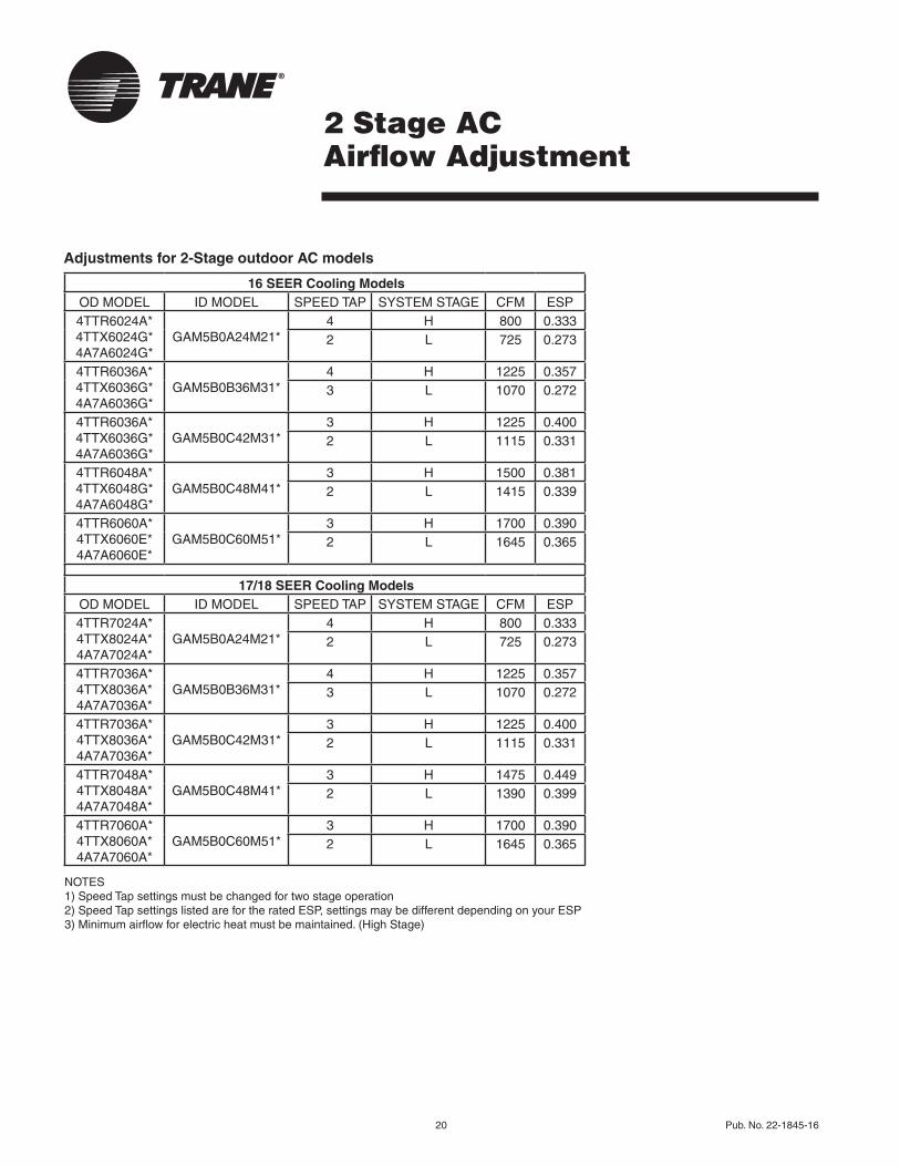
2 Stage AC Airflow Adjustment
Adjustments for 2-Stage outdoor AC models
16 SEER Cooling ModelsODMODEL IDMODEL SPEEDTAP SYSTEMSTAGE CFM ESP4TTR6024A*4TTX6024G* 4A7A6024G*
GAM5B0A24M21*4 H 800 0.3332 L 725 0.273
4TTR6036A*4TTX6036G* 4A7A6036G*
GAM5B0B36M31*4 H 1225 0.3573 L 1070 0.272
4TTR6036A*4TTX6036G* 4A7A6036G*
GAM5B0C42M31*3 H 1225 0.4002 L 1115 0.331
4TTR6048A*4TTX6048G* 4A7A6048G*
GAM5B0C48M41*3 H 1500 0.3812 L 1415 0.339
4TTR6060A*4TTX6060E* 4A7A6060E*
GAM5B0C60M51*3 H 1700 0.3902 L 1645 0.365
17/18 SEER Cooling ModelsODMODEL IDMODEL SPEEDTAP SYSTEMSTAGE CFM ESP4TTR7024A*4TTX8024A* 4A7A7024A*
GAM5B0A24M21*4 H 800 0.3332 L 725 0.273
4TTR7036A*4TTX8036A* 4A7A7036A*
GAM5B0B36M31*4 H 1225 0.3573 L 1070 0.272
4TTR7036A*4TTX8036A* 4A7A7036A*
GAM5B0C42M31*3 H 1225 0.4002 L 1115 0.331
4TTR7048A*4TTX8048A* 4A7A7048A*
GAM5B0C48M41*3 H 1475 0.4492 L 1390 0.399
4TTR7060A*4TTX8060A* 4A7A7060A*
GAM5B0C60M51*3 H 1700 0.3902 L 1645 0.365
NOTES 1)SpeedTapsettingsmustbechangedfortwostageoperation 2)SpeedTapsettingslistedarefortheratedESP,settingsmaybedifferentdependingonyourESP 3)Minimumairflowforelectricheatmustbemaintained.(HighStage)

Pub. No. 22-1845-16 21
Adjustments for 2-Stage outdoor HP models
2 Stage HP Airflow Adjustment
16 SEER Heat Pump ModelsODMODEL IDMODEL SPEEDTAP SYSTEMSTAGE CFM ESP
4TWR6024A*44TWX6024G*4 4A6H6024G*4
GAM5B0A24M21*4 H 800 0.3333 L 750 0.293
4TWR6024A*4TWX6024G* 4A6H6024G*
GAM5B0B30M21*3 H 750 0.3832 L 665 0.301
4TWR6036A*4TWX6036E* 4A6H6036E*
GAM5B0B36M31*4 H 1150 0.5003 L 1005 0.382
4TWR6048A*4TWX6048G* 4A6H6048G*
GAM5B0C42M31*4 H 1375 0.4683 L 1235 0.378
4TWR6048A*4TWX6048G* 4A6H6048G*
GAM5B0C48M41*4 H 1575 0.4002 L 1420 0.325
4TWR6060A*4TWX6060E* 4A6H6060E*
GAM5B0C60M51*3 H 1700 0.3902 L 1645 0.365
17/18 SEER Heat Pump ModelsODMODEL IDMODEL SPEEDTAP SYSTEMSTAGE CFM ESP
4TWR7024A*44TWX8024A*4 4A6H7024A*4
GAM5B0A24M21*4 H 800 0.3333 L 750 0.293
4TWR7024A*4TWX8024A* 4A6H7024A*
GAM5B0B30M21*3 H 750 0.3832 L 665 .0301
4TWR7036A*4TWX8036A* 4A6H7036A*
GAM5B0B36M31*4 H 1150 0.5003 L 1005 0.382
4TWR7048A*4TWX8048A* 4A6H7048A*
GAM5B0C48M41*4 H 1575 0.4002 L 1420 0.325
4TWR7060A*4TWX8060A* 4A6H7060A*
GAM5B0C60M51*3 H 1700 0.3902 L 1645 0.365
NOTES 1)SpeedTapsettingsmustbechangedfortwostageoperation 2)SpeedTapsettingslistedarefortheratedESP,settingsmaybedifferentdependingonyourESP 3)Minimumairflowforelectricheatmustbemaintained.(HighStage)4)Subcoolingmustbeadjustedto9°Fforthismatch
System Matched with: Indoor Unit Model No. Outdoor Unit Model No. Subcooling
16-18SEERHP GAM5B0A24M21*4TWR6024A*,4TWX6024G* 4A6H6024G*,4TWR7024A*4TWX8024A*,4A6H7024A*
9°
Allothermatchesmustbechargedperthenameplatecharginginstructions.
22 Pub. No. 22-1845-16
ElectricalData
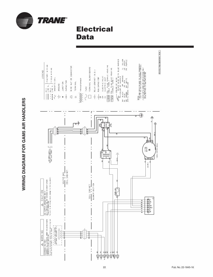
WIR
ING
DIA
GR
AM
FO
R G
AM
5 A
IR H
AN
DL
ER
S
Pub.No.22-1845-16 23
FieldWiring
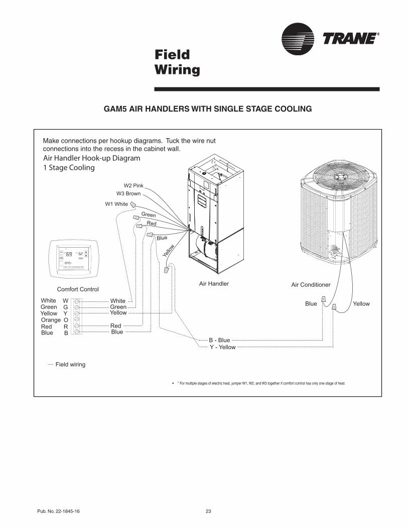
GAM5 AIR HANDLERS WITH SINGLE STAGE COOLING
• * For multiple stages of electric heat, jumper W1, W2, and W3 together if comfort control has only one stage of heat.
Makeconnectionsperhookupdiagrams.Tuckthewirenutconnectionsintotherecessinthecabinetwall.Air Handler Hook-up Diagram1 Stage Cooling
Red
YellowGreenWhite
Blue
YellowGreenWhite
Blue BB - Blue
BlueWGY
Y - Yellow
Yellow
RRedOOrange
Comfort ControlAir Handler Air Conditioner
Field wiring
Red
Blue
Yello
w
Green
W2 PinkW3 Brown
W1 White
24 Pub. No. 22-1845-16
FieldWiring
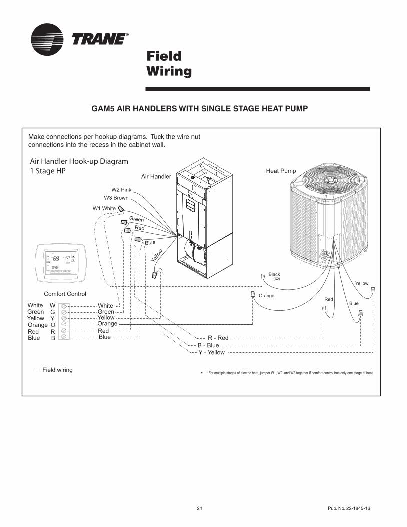
GAM5 AIR HANDLERS WITH SINGLE STAGE HEAT PUMP
Makeconnectionsperhookupdiagrams.Tuckthewirenutconnectionsintotherecessinthecabinetwall.
Air Handler Hook-up Diagram1 Stage HP
Red
YellowGreenWhite
Blue
OrangeYellowGreenWhite
Blue BB - Blue
R - Red
WGY
Y - Yellow
RRedOOrange
Comfort Control
Air Handler
Field wiring
Yellow
Blue
Black(X2)
RedOrange
Heat Pump
Red
Blue
Yello
w
Green
W2 PinkW3 Brown
W1 White
• * For multiple stages of electric heat, jumper W1, W2, and W3 together if comfort control has only one stage of heat
Pub. No. 22-1845-16 25
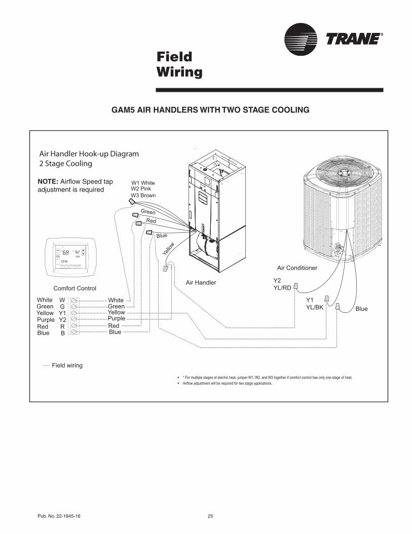
GAM5 AIR HANDLERS WITH TWO STAGE COOLING
FieldWiring
NOTE:AirflowSpeedtapadjustmentisrequired
Air Handler Hook-up Diagram2 Stage Cooling
Red
YellowGreenWhite
Blue
PurpleYellowGreenWhite
Blue B
BlueWGY1
Y1 YL/BK
Y2 YL/RD
RRedY2Purple
Comfort ControlAir Handler
Air Conditioner
Field wiring
Red
Blue
Yello
w
Green
W2 PinkW3 Brown
W1 White
• * For multiple stages of electric heat, jumper W1, W2, and W3 together if comfort control has only one stage of heat. • Airflow adjustment will be required for two stage applications.
26 Pub. No. 22-1845-16
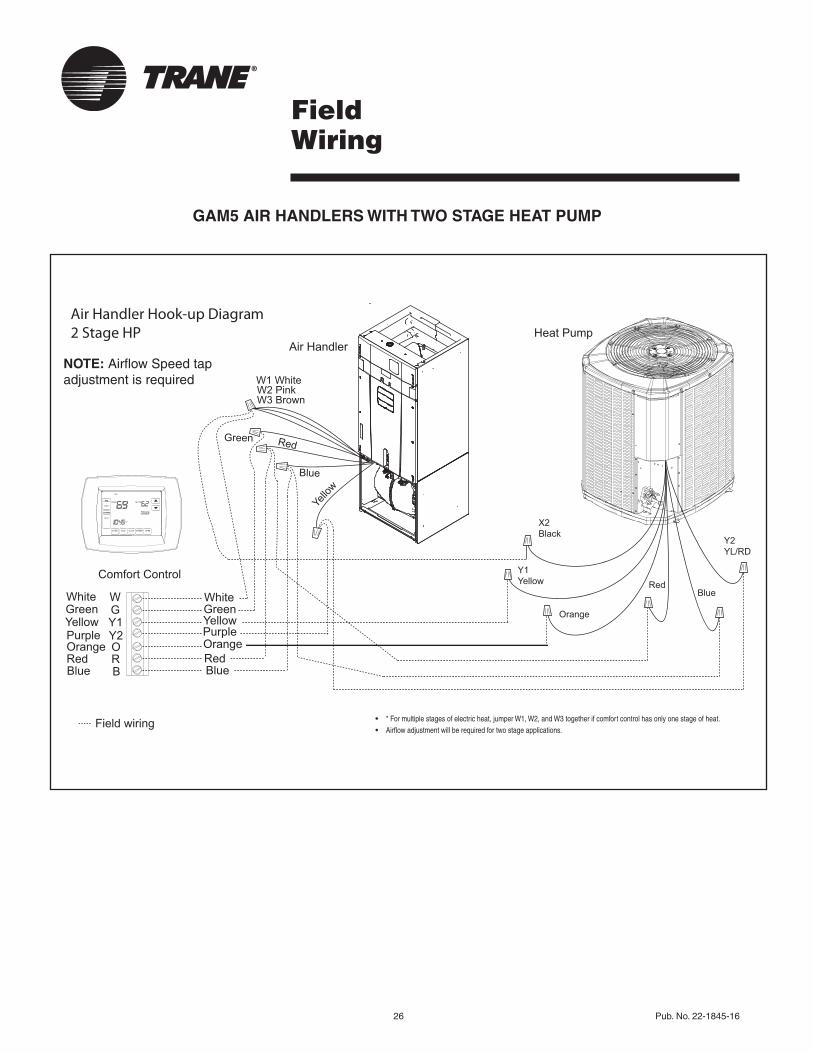
GAM5 AIR HANDLERS WITH TWO STAGE HEAT PUMP
FieldWiring
NOTE:AirflowSpeedtapadjustmentisrequired
Air Handler Hook-up Diagram2 Stage HP
Red
YellowPurple
GreenWhite
Blue
Orange
YellowGreenWhite
Blue B
WGY1
RRedOOrange
Comfort Control
Air Handler
Field wiring
Y2Purple
Y2YL/RD
Blue
X2Black
RedY1Yellow
Heat Pump
Orange
Red
Blue
Green
W2 PinkW3 Brown
W1 White
Yello
w
• * For multiple stages of electric heat, jumper W1, W2, and W3 together if comfort control has only one stage of heat. • Airflow adjustment will be required for two stage applications.

Pub.No.22-1845-16 27
GAM5Convertibility
Multi-position Air Handler
Airflo
w
AirflowAirflow
Air
flo
w
Upflow Condensate Drains
Refrigerant Connections
Downflow Condensate Drains
Refrigerant Connections
Vertical Downflow*(as shipped)
Horizontal Left*
Vertical Upflow*
Horizontal Right*
Horizontal Left Condensate Drains
Refrigerant Connections
Horizontal Right Condensate Drains
Refrigerant Connections
* Note: No internal modifications required for any position.1 Badge rotation will keep brand in correct position
1
1
1
1
28 Pub. No. 22-1845-16
Dimensions
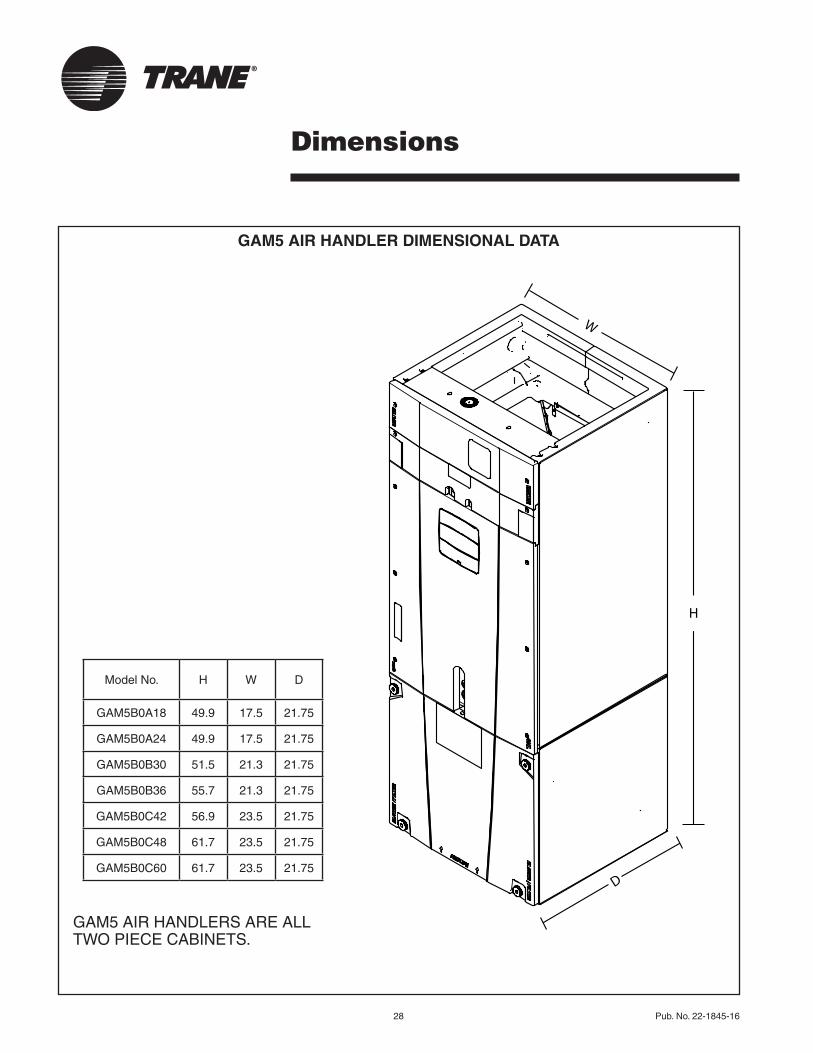
GAM5 AIR HANDLER DIMENSIONAL DATA
GAM5AIRHANDLERSAREALLTWOPIECECABINETS.
ModelNo. H W D
GAM5B0A18 49.9 17.5 21.75
GAM5B0A24 49.9 17.5 21.75
GAM5B0B30 51.5 21.3 21.75
GAM5B0B36 55.7 21.3 21.75
GAM5B0C42 56.9 23.5 21.75
GAM5B0C48 61.7 23.5 21.75
GAM5B0C60 61.7 23.5 21.75D
H
W
Pub.No.22-1845-16 29
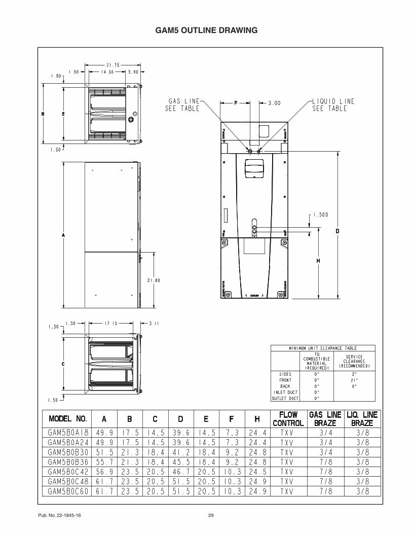
GAM5 OUTLINE DRAWING

30 Pub. No. 22-1845-16

Pub.No.22-1845-16 31
Trane6200 Troup HighwayTyler, TX 75707www.trane.com
04/14
The manufacturer has a policy of continuous product and product data improvement and it reserves the right to change design and specifications without notice.