Modular Multi-position Air Handlers › content › dam › Trane › Commercial › global... ·...
28
Black Epoxy Coil TAM4A0A18S11ED TAM4A0A24S21ED TAM4A0A30S21ED TAM4A0A36S31ED TAM4A0B42S31ED TAM4A0C48S41ED TAM4A0C60S51ED Standard Coil TAM4A0A18S11SD TAM4A0A24S21SD TAM4A0A30S21SD TAM4A0A36S31SD TAM4A0B42S31SD TAM4A0C48S41SD TAM4A0C60S51SD Modular Multi-position Air Handlers PUB. NO. 22-1848-12
Transcript of Modular Multi-position Air Handlers › content › dam › Trane › Commercial › global... ·...

Black Epoxy CoilTAM4A0A18S11EDTAM4A0A24S21EDTAM4A0A30S21EDTAM4A0A36S31EDTAM4A0B42S31EDTAM4A0C48S41EDTAM4A0C60S51ED
Standard CoilTAM4A0A18S11SDTAM4A0A24S21SDTAM4A0A30S21SDTAM4A0A36S31SDTAM4A0B42S31SDTAM4A0C48S41SDTAM4A0C60S51SD
ModularMulti-position Air Handlers
PUB. NO. 22-1848-12

2 Pub. No. 22-1848-12
Featuresand Benefits
© 2016 Trane
• Unique Cabinet Design - Double Wall Foamed and Formed
Cabinet System - Water Proof Cabinet Design - > R-4.2 Insulating Value (Avg
Insulating Value R-8.2) - Composite Foamed Cabinet Doors - Sweat Eliminating Cabinet Design - Loose Fiber Eliminating Cabinet
Design - Smooth Cleanable Cabinet Design - 2% or Less air leakage - Precision Durable Door Seals - Modular Cabinet • Multi-Position UP/Down Flow
Horizontal Left /Right• Side Return Option• Braze in Refrigerant Connection • Primary/Secondary Condensate
Connections • Premarked Conduit Connection
Locations• Vortica Blower with Integrated Slide
Deck for Easy Removal• Polarized Plug connections on
Blower• Control Protection Pocket• Aluminum Coil with Integrated Slide
Deck for Easy Removal
• 5 year warranty • 10-year warranty registered• Optional extended warranty
available
• Polarized Plug connections on Coil EEV
• Slide in Electric Heaters• Polarized Plug connections for
Electric Heater• Labeled Panels and connections• 1-1/4" to 1" And 3/4" to 1/2" Conduit
connection on Left, Right and Top• Molded in 1" Standard Filter rail • Electronic Expansion Valve (EEV)
With Low Ambient and Low Superheat Protection
• Dual Refrigerant Compatible as Shipped
• Low Voltage Terminal Connection Point
• 8 Alert Codes• Enhanced Coil Fin Patented• Blow Through Design• PSC 3 Speed Motor (1-1/2 to 4 ton)• High Efficiency ECM Motor (5 ton)• Maximum Width of 23.5"• Compact 20.8" depth with doors
removed• Integrated Horizontal Drain pans• Single Color• Fused 24V Power• Safety Door Switch
Pub. No. 22-1848-12 3
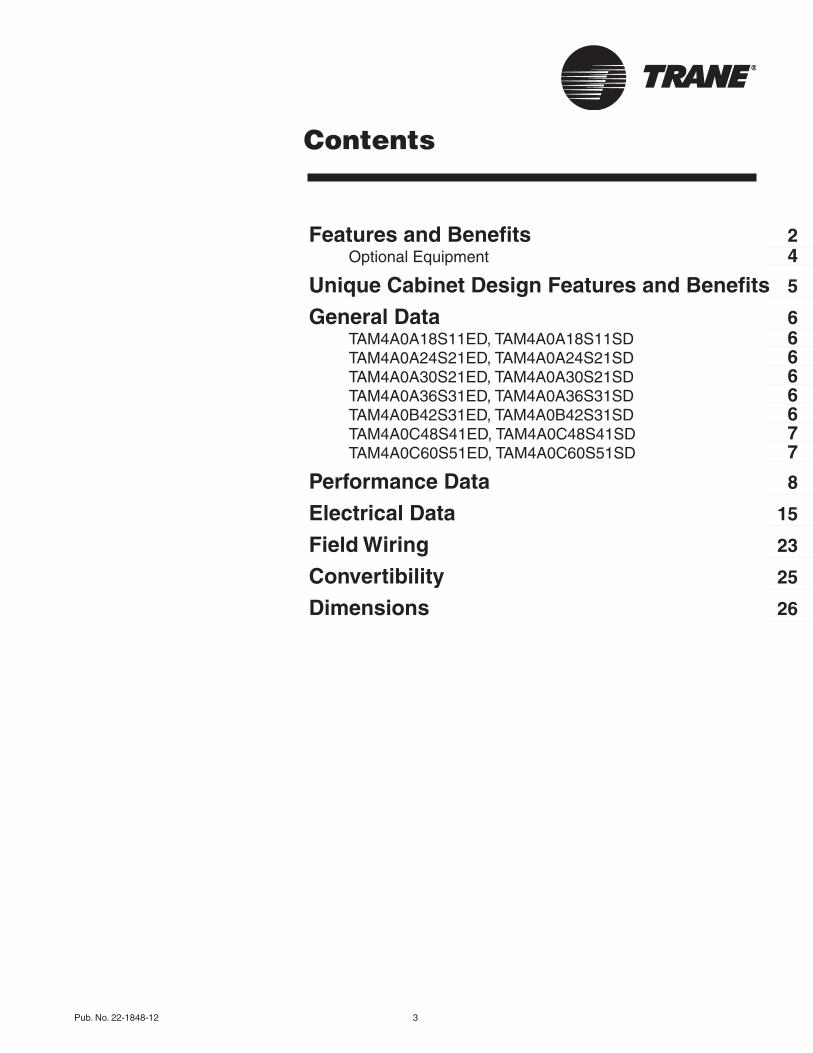
Contents
Features and Benefits 2Optional Equipment 4
Unique Cabinet Design Features and Benefits 5
General Data 6TAM4A0A18S11ED, TAM4A0A18S11SD 6TAM4A0A24S21ED, TAM4A0A24S21SD 6TAM4A0A30S21ED, TAM4A0A30S21SD 6TAM4A0A36S31ED, TAM4A0A36S31SD 6TAM4A0B42S31ED, TAM4A0B42S31SD 6TAM4A0C48S41ED, TAM4A0C48S41SD 7TAM4A0C60S51ED, TAM4A0C60S51SD 7
Performance Data 8
Electrical Data 15
Field Wiring 23
Convertibility 25
Dimensions 26
4 Pub. No. 22-1848-12
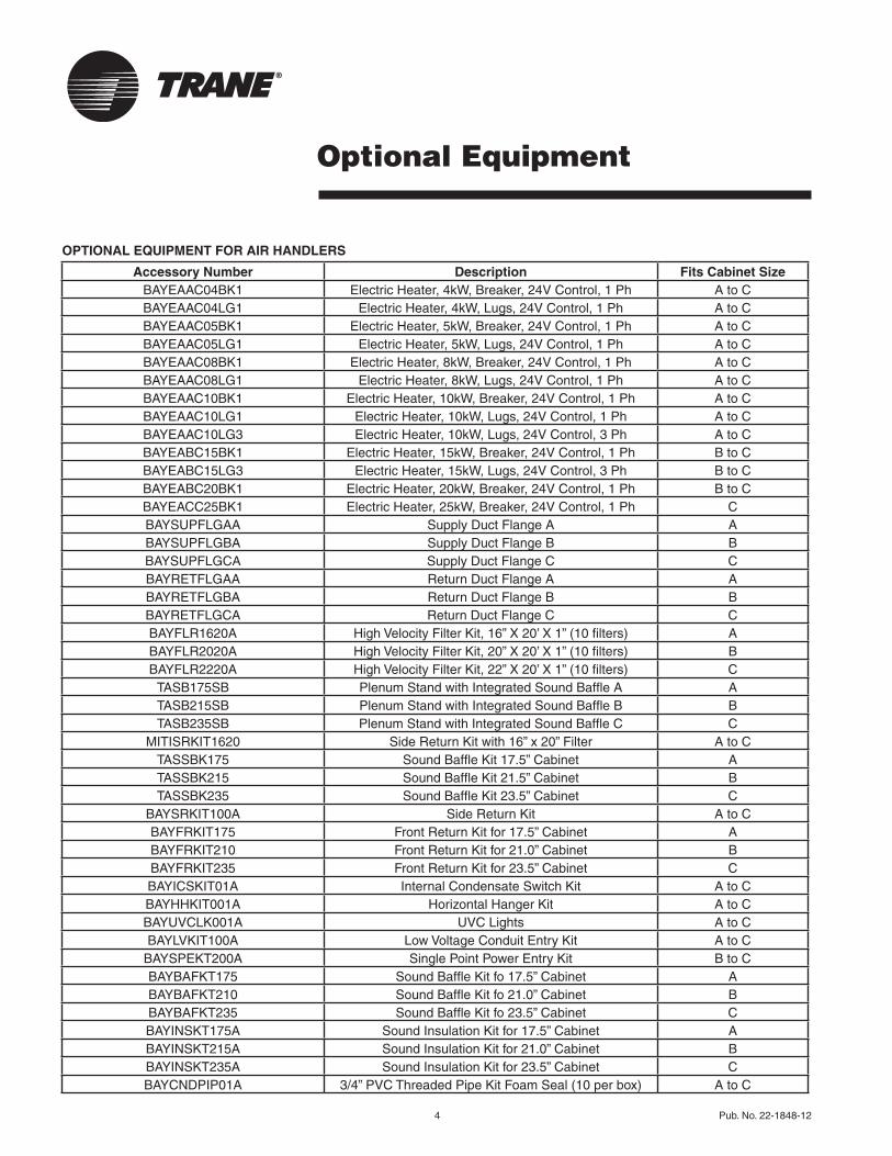
Optional Equipment
OPTIONAL EQUIPMENT FOR AIR HANDLERS
Accessory Number Description Fits Cabinet SizeBAYEAAC04BK1 Electric Heater, 4kW, Breaker, 24V Control, 1 Ph A to CBAYEAAC04LG1 Electric Heater, 4kW, Lugs, 24V Control, 1 Ph A to CBAYEAAC05BK1 Electric Heater, 5kW, Breaker, 24V Control, 1 Ph A to CBAYEAAC05LG1 Electric Heater, 5kW, Lugs, 24V Control, 1 Ph A to CBAYEAAC08BK1 Electric Heater, 8kW, Breaker, 24V Control, 1 Ph A to CBAYEAAC08LG1 Electric Heater, 8kW, Lugs, 24V Control, 1 Ph A to CBAYEAAC10BK1 Electric Heater, 10kW, Breaker, 24V Control, 1 Ph A to CBAYEAAC10LG1 Electric Heater, 10kW, Lugs, 24V Control, 1 Ph A to CBAYEAAC10LG3 Electric Heater, 10kW, Lugs, 24V Control, 3 Ph A to CBAYEABC15BK1 Electric Heater, 15kW, Breaker, 24V Control, 1 Ph B to CBAYEABC15LG3 Electric Heater, 15kW, Lugs, 24V Control, 3 Ph B to CBAYEABC20BK1 Electric Heater, 20kW, Breaker, 24V Control, 1 Ph B to CBAYEACC25BK1 Electric Heater, 25kW, Breaker, 24V Control, 1 Ph CBAYSUPFLGAA Supply Duct Flange A ABAYSUPFLGBA Supply Duct Flange B BBAYSUPFLGCA Supply Duct Flange C CBAYRETFLGAA Return Duct Flange A ABAYRETFLGBA Return Duct Flange B BBAYRETFLGCA Return Duct Flange C CBAYFLR1620A High Velocity Filter Kit, 16” X 20’ X 1” (10 filters) ABAYFLR2020A High Velocity Filter Kit, 20” X 20’ X 1” (10 filters) BBAYFLR2220A High Velocity Filter Kit, 22” X 20’ X 1” (10 filters) C
TASB175SB Plenum Stand with Integrated Sound Baffle A ATASB215SB Plenum Stand with Integrated Sound Baffle B BTASB235SB Plenum Stand with Integrated Sound Baffle C C
MITISRKIT1620 Side Return Kit with 16” x 20” Filter A to CTASSBK175 Sound Baffle Kit 17.5” Cabinet ATASSBK215 Sound Baffle Kit 21.5” Cabinet BTASSBK235 Sound Baffle Kit 23.5” Cabinet C
BAYSRKIT100A Side Return Kit A to CBAYFRKIT175 Front Return Kit for 17.5” Cabinet ABAYFRKIT210 Front Return Kit for 21.0” Cabinet BBAYFRKIT235 Front Return Kit for 23.5” Cabinet CBAYICSKIT01A Internal Condensate Switch Kit A to CBAYHHKIT001A Horizontal Hanger Kit A to CBAYUVCLK001A UVC Lights A to CBAYLVKIT100A Low Voltage Conduit Entry Kit A to C
BAYSPEKT200A Single Point Power Entry Kit B to CBAYBAFKT175 Sound Baffle Kit fo 17.5” Cabinet ABAYBAFKT210 Sound Baffle Kit fo 21.0” Cabinet BBAYBAFKT235 Sound Baffle Kit fo 23.5” Cabinet CBAYINSKT175A Sound Insulation Kit for 17.5” Cabinet ABAYINSKT215A Sound Insulation Kit for 21.0” Cabinet BBAYINSKT235A Sound Insulation Kit for 23.5” Cabinet CBAYCNDPIP01A 3/4” PVC Threaded Pipe Kit Foam Seal (10 per box) A to C
Pub. No. 22-1848-12 5
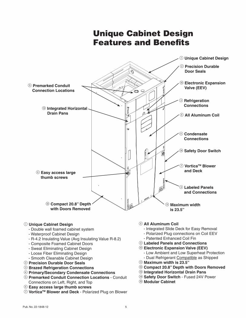
Unique Cabinet DesignFeatures and Benefits
5 Premarked Conduit Connection Locations
e Integrated Horizontal Drain Pans
6 Easy access large thumb screws
w Compact 20.8” Depth with Doors Removed
1 Unique Cabinet Design
2 Precision Durable Door Seals
0 Electronic Expansion Valve (EEV)
3 Refrigeration Connections
8 All Aluminum Coil
r Safety Door Switch
4 Condensate Connections
q Maximum width is 23.5”
7 VorticaTM Blower and Deck
9 Labeled Panels and Connections
1 Unique Cabinet Design - Double wall foamed cabinet system - Waterproof Cabinet Design - R-4.2 Insulating Value (Avg Insulating Value R-8.2) - Composite Foamed Cabinet Doors - Sweat Eliminating Cabinet Design - Loose Fiber Eliminating Design - Smooth Cleanable Cabinet Design2 Precision Durable Door Seals3 Brazed Refrigeration Connections4 Primary/Secondary Condensate Connections5 Premarked Conduit Connection Locations - Conduit
Connections on Left, Right, and Top6 Easy access large thumb screws7 VorticaTM Blower and Deck - Polarized Plug on Blower
8 All Aluminum Coil - Integrated Slide Deck for Easy Removal - Polarized Plug connections on Coil EEV - Patented Enhanced Coil Fin9 Labeled Panels and Connections0 Electronic Expansion Valve (EEV) - Low Ambient and Low Superheat Protection - Dual Refrigerant Compatible as Shippedq Maximum width is 23.5”w Compact 20.8” Depth with Doors Removede Integrated Horizontal Drain Pansr Safety Door Switch - Fused 24V Powert Modular Cabinet

6 Pub. No. 22-1848-12
GeneralData
PRODUCT SPECIFICATIONSMODEL TAM4A0A18S11ED TAM4A0A18S11SDRATED VOLTS/PH/HZ. 208-230/1/60RATINGS 1 See O.D. SpecificationsINDOOR COIL — Type Plate FinRows — F.P.I. 3 - 14Face Area (sq. ft.) 3.21Tube Size (in.) 3/8Refrigerant Control EEVDrain Conn. Size (in.) 2 3/4 NPTDUCT CONNECTIONS See Outline DrawingINDOOR FAN — Type CentrifugalDiameter-Width (In.) 11 X 8No. Used 1Drive - No. Speeds Direct - 3CFM vs. in. w.g. See Fan Performance TableNo. Motors — H.P. 1 - 1/3Motor Speed R.P.M. 825Volts/Ph/Hz 208-230/1/60F.L. Amps - L.R. Amps 2.0 - 4.1FILTERFilter Furnished? NoType Recommended ThrowawayNo.-Size-Thickness 1 - 16 X 20 - 1 in.REFRIGERANT R-410ARef. Line Connections BrazedCoupling or Conn. Size — in. Gas 3/4Coupling or Conn. Size — in. Liq. 3/8DIMENSIONS H x W x DCrated (In.) 51 x 20 x 24-1/2Uncrated 49-15/16 x 17-1/2 x 21-13/16WEIGHTShipping (Lbs.) / Net (Lbs.) 123/113
TAM4A0A24S21EDTAM4A0A24S21SD
208-230/1/60See O.D. Specifications
Plate Fin3 - 143.213/8
EEV 3/4 NPT
See Outline DrawingCentrifugal
10 X 8 1
Direct - 3 See Fan Performance Table
1 - 1/41075
208-230/1/601.3 - 2.6
NoThrowaway
1 - 16 X 20 - 1 in.R-410ABrazed
3/43/8
H x W x D51 x 20 x 24-1/2
49-15/16 x 17-1/2 x 21-13/16
126/116
TAM4A0A30S21EDTAM4A0A30S21SD
208-230/1/60See O.D. Specifications
Plate Fin3 - 143.213/8
EEV 3/4 NPT
See Outline DrawingCentrifugal
10 X 101
Direct - 5See Fan Performance Table
1 - 1/31075
208-230/1/601.7 - 3.5
NoThrowaway
1 - 16 X 20 - 1 in.R-410ABrazed
3/43/8
H x W x D51 x 20 x 24-1/2
49-15/16 x 17-1/2 x 21-13/16
127/117
PRODUCT SPECIFICATIONSMODEL TAM4A0A36S31ED TAM4A0A36S31SDRATED VOLTS/PH/HZ. 208-230/1/60RATINGS 1 See O.D. SpecificationsINDOOR COIL — Type Plate FinRows — F.P.I. 3 - 14Face Area (sq. ft.) 3.67Tube (in.) 3/8Refrigerant Control EEV Drain Conn. Size (in.) 2 3/4 NPTDUCT CONNECTIONS See Outline DrawingINDOOR FAN — Type CentrifugalDiameter-Width (In.) 11 X 8No. Used 1Drive - No. Speeds Direct - 3CFM vs. in. w.g. See Fan Performance TableNo. Motors — H.P. 1 - 1/2Motor Speed R.P.M. 1075Volts/Ph/Hz 208-230/1/60F.L. Amps 2.4 - 3.8FILTERFilter Furnished? NoType Recommended ThrowawayNo.-Size-Thickness 1 - 16 X 20 - 1 in.REFRIGERANT R-410ARef. Line Connections BrazedCoupling or Conn. Size — in. Gas 3/4Coupling or Conn. Size — in. Liq. 3/8DIMENSIONS H x W x DCrated (In.) 51 x 20 x 24-1/2 Uncrated 49-15/16 x 17-1/2 x 21-13/16WEIGHTShipping (Lbs.) / Net (Lbs.) 131/120
TAM4A0B42S31EDTAM4A0B42S31SD
208-230/1/60See O.D. Specifications
Plate Fin3 - 145.043/8
EEV 3/4 NPT
See Outline DrawingCentrifugal
10 X 101
Direct - 3See Fan Performance Table
1 - 1/21075
208-230/1/602.7 - 5.0
NoThrowaway
1 - 20 X 20 - 1 in.R-410ABrazed
7/83/8
H x W x D56-13/16 x 23-1/2 x 24-1/2
55-23/32 x 21-5/16 x 21-13/16
144/133
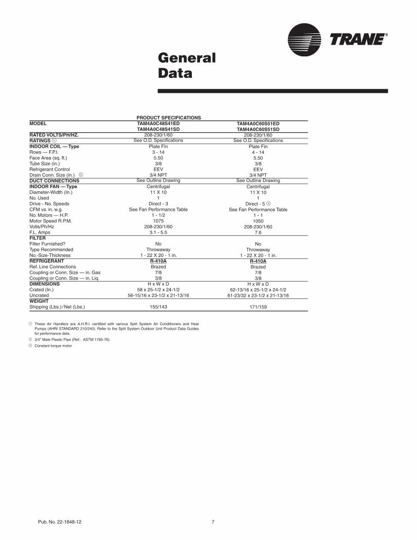
Pub. No. 22-1848-12 7
GeneralData
1 These Air Handlers are A.H.R.I. certified with various Split System Air Conditioners and Heat Pumps (AHRI STANDARD 210/240). Refer to the Split System Outdoor Unit Product Data Guides for performance data.
2 3/4" Male Plastic Pipe (Ref.: ASTM 1785-76)
3 Constant torque motor
PRODUCT SPECIFICATIONSMODEL TAM4A0C48S41ED TAM4A0C48S41SDRATED VOLTS/PH/HZ. 208-230/1/60RATINGS 1 See O.D. SpecificationsINDOOR COIL — Type Plate FinRows — F.P.I. 3 - 14Face Area (sq. ft.) 5.50Tube Size (in.) 3/8Refrigerant Control EEV Drain Conn. Size (in.) 2 3/4 NPTDUCT CONNECTIONS See Outline DrawingINDOOR FAN — Type CentrifugalDiameter-Width (In.) 11 X 10No. Used 1Drive - No. Speeds Direct - 3CFM vs. in. w.g. See Fan Performance TableNo. Motors — H.P. 1 - 1/2Motor Speed R.P.M. 1075Volts/Ph/Hz 208-230/1/60F.L. Amps 3.1 - 5.5FILTERFilter Furnished? NoType Recommended ThrowawayNo.-Size-Thickness 1 - 22 X 20 - 1 in.REFRIGERANT R-410ARef. Line Connections BrazedCoupling or Conn. Size — in. Gas 7/8Coupling or Conn. Size — in. Liq. 3/8DIMENSIONS H x W x DCrated (In.) 58 x 25-1/2 x 24-1/2 Uncrated 56-15/16 x 23-1/2 x 21-13/16WEIGHTShipping (Lbs.) / Net (Lbs.) 155/143
TAM4A0C60S51ED TAM4A0C60S51SD
208-230/1/60See O.D. Specifications
Plate Fin4 - 145.503/8
EEV3/4 NPT
See Outline DrawingCentrifugal
11 X 101
Direct - 5 3See Fan Performance Table
1 - 11050
208-230/1/607.6
NoThrowaway
1 - 22 X 20 - 1 in.R-410ABrazed
7/83/8
H x W x D62-13/16 x 25-1/2 x 24-1/2
61-23/32 x 23-1/2 x 21-13/16
171/159
8 Pub. No. 22-1848-12
PerformanceData
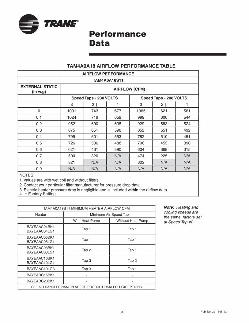
TAM4A0A18 AIRFLOW PERFORMANCE TABLE
AIRFLOW PERFORMANCE
TAM4A0A18S11
EXTERNAL STATIC (in w.g)
AIRFLOW (CFM)
Speed Taps - 230 VOLTS Speed Taps - 208 VOLTS
3 2 † 1 3 2 † 1
0 1091 743 677 1065 621 561
0.1 1024 719 659 999 606 544
0.2 952 690 635 929 583 524
0.3 875 651 598 852 551 492
0.4 799 601 553 782 510 451
0.5 726 536 488 706 453 390
0.6 621 431 390 604 369 315
0.7 500 320 N/A 474 225 N/A
0.8 321 N/A N/A 302 N/A N/A
0.9 N/A N/A N/A N/A N/A N/A
NOTES:1. Values are with wet coil and without filters.2. Contact your particular filter manufacturer for pressure drop data. 3. Electric heater pressure drop is negligible and is included within the airflow data.4. † Factory Setting
Note: Heating and cooling speeds are the same, factory set at Speed Tap #2.
TAM4A0A18S11 MINIMUM HEATER AIRFLOW CFM
Heater Minimum Air Speed Tap
With Heat Pump Without Heat Pump
BAYEAAC04BK1 BAYEAAC04LG1
Tap 1 Tap 1
BAYEAAC05BK1 BAYEAAC05LG1
Tap 1 Tap 1
BAYEAAC08BK1 BAYEAAC08LG1
Tap 2 Tap 1
BAYEAAC10BK1 BAYEAAC10LG1
Tap 3 Tap 2
BAYEAAC10LG3 Tap 3 Tap 1
BAYEABC15BK1 - -
BAYEABC20BK1 - -
SEE AIR HANDLER NAMEPLATE OR PRODUCT DATA FOR EXCEPTIONS

Pub. No. 22-1848-12 9
Note: Heating and cooling speeds are the same, factory set at Speed Tap #2.
AIRFLOW PERFORMANCE
TAM4A0A24S21
EXTERNAL STATIC (in w.g)
AIRFLOW (CFM)
Speed Taps - 230 VOLTS Speed Taps - 208 VOLTS
3 2 † 1 3 2 † 1
0 1036 871 774 929 746 663
0.1 1008 838 747 890 720 636
0.2 965 806 712 856 686 605
0.3 922 767 676 815 654 564
0.4 875 726 638 777 618 518
0.5 823 681 591 733 568 464
0.6 769 608 505 675 479 398
0.7 673 498 422 572 393 N/A
0.8 515 402 322 436 303 N/A
0.9 339 242 N/A 279 N/A N/A
NOTES:1. Values are with wet coil and without filters.2. Contact your particular filter manufacturer for pressure drop data. 3. Electric heater pressure drop is negligible and is included within the airflow data.4. † Factory Setting
PerformanceData
TAM4A0A24 AIRFLOW PERFORMANCE TABLE
TAM4A0A24S21 MINIMUM HEATER AIRFLOW CFM
Heater Minimum Air Speed Tap
With Heat Pump Without Heat Pump
BAYEAAC04BK1 BAYEAAC04LG1
Tap 1 Tap 1
BAYEAAC05BK1 BAYEAAC05LG1
Tap 1 Tap 1
BAYEAAC08BK1 BAYEAAC08LG1
Tap 1 Tap 1
BAYEAAC10BK1 BAYEAAC10LG1 Tap 2 1 Tap 1
BAYEAAC10LG3 Tap 3 Tap 1
BAYEABC15BK1 - -
BAYEABC20BK1 - -
SEE AIR HANDLER NAMEPLATE OR PRODUCT DATA FOR EXCEPTIONS1 Minimum Speed Tap is 3 for Horizontal Left only.

10 Pub. No. 22-1848-12
TAM4A0B30 AIRFLOW PERFORMANCE TABLE
PerformanceData
Note: Heating and cooling speeds are the same, factory set at Speed Tap #2.
AIRFLOW PERFORMANCE
TAM4A0A30S21
EXTERNAL STATIC (in w.g)
AIRFLOW (CFM)
Speed Taps - 230 VOLTS Speed Taps - 208 VOLTS
3 2 † 1 3 2 † 1
0 1202 1013 944 1145 867 798
0.1 1156 985 922 1102 847 779
0.2 1102 947 892 1059 838 774
0.3 1049 909 859 1006 795 733
0.4 1000 867 822 958 774 714
0.5 943 823 783 900 726 672
0.6 883 767 738 843 681 621
0.7 822 709 658 778 601 542
0.8 749 583 542 697 492 441
0.9 684 440 N/A 628 N/A N/A
1.0 613 N/A N/A 549 N/A N/A
NOTES:1. Values are with wet coil and without filters.2. Contact your particular filter manufacturer for pressure drop data. 3. Electric heater pressure drop is negligible and is included within the airflow data.4. † Factory Setting
TAM4A0A30S21 MINIMUM HEATER AIRFLOW CFM
Heater Minimum Air Speed Tap
With Heat Pump Without Heat Pump
BAYEAAC04BK1 BAYEAAC04LG1
Tap 1 Tap 1
BAYEAAC05BK1 BAYEAAC05LG1
Tap 1 Tap 1
BAYEAAC08BK1 BAYEAAC08LG1
Tap 2 Tap 1
BAYEAAC10BK1 BAYEAAC10LG1
Tap 2 Tap 1
BAYEAAC10LG3 Tap 1 Tap 1
BAYEABC15BK1 Tap 3 Tap 2
BAYEABC15LG3 Tap 3 1 Tap 1 1
BAYEABC20BK1 - -
SEE AIR HANDLER NAMEPLATE OR PRODUCT DATA FOR EXCEPTIONS 1 Heater not qualified for 240V in downflow installations.
Pub. No. 22-1848-12 11
PerformanceData
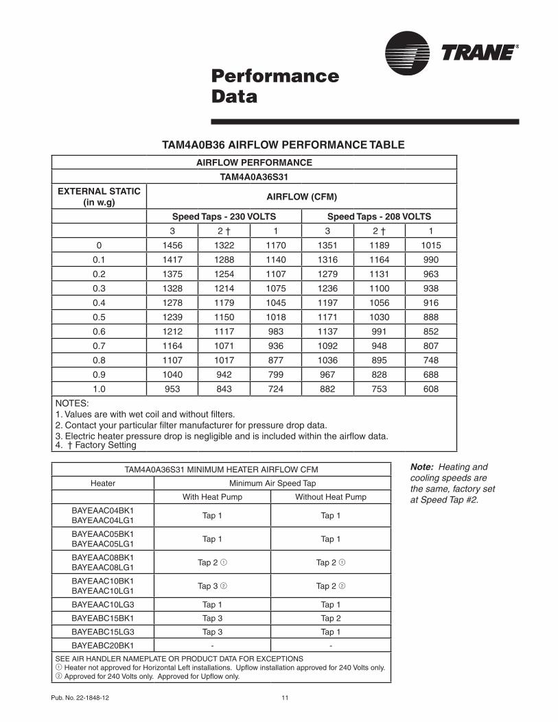
TAM4A0B36 AIRFLOW PERFORMANCE TABLE
AIRFLOW PERFORMANCE
TAM4A0A36S31
EXTERNAL STATIC (in w.g)
AIRFLOW (CFM)
Speed Taps - 230 VOLTS Speed Taps - 208 VOLTS
3 2 † 1 3 2 † 1
0 1456 1322 1170 1351 1189 1015
0.1 1417 1288 1140 1316 1164 990
0.2 1375 1254 1107 1279 1131 963
0.3 1328 1214 1075 1236 1100 938
0.4 1278 1179 1045 1197 1056 916
0.5 1239 1150 1018 1171 1030 888
0.6 1212 1117 983 1137 991 852
0.7 1164 1071 936 1092 948 807
0.8 1107 1017 877 1036 895 748
0.9 1040 942 799 967 828 688
1.0 953 843 724 882 753 608
NOTES:1. Values are with wet coil and without filters.2. Contact your particular filter manufacturer for pressure drop data. 3. Electric heater pressure drop is negligible and is included within the airflow data.4. † Factory Setting
Note: Heating and cooling speeds are the same, factory set at Speed Tap #2.
TAM4A0A36S31 MINIMUM HEATER AIRFLOW CFM
Heater Minimum Air Speed Tap
With Heat Pump Without Heat Pump
BAYEAAC04BK1 BAYEAAC04LG1
Tap 1 Tap 1
BAYEAAC05BK1 BAYEAAC05LG1
Tap 1 Tap 1
BAYEAAC08BK1 BAYEAAC08LG1
Tap 2 1 Tap 2 1
BAYEAAC10BK1 BAYEAAC10LG1
Tap 3 2 Tap 2 2
BAYEAAC10LG3 Tap 1 Tap 1
BAYEABC15BK1 Tap 3 Tap 2
BAYEABC15LG3 Tap 3 Tap 1
BAYEABC20BK1 - -
SEE AIR HANDLER NAMEPLATE OR PRODUCT DATA FOR EXCEPTIONS1 Heater not approved for Horizontal Left installations. Upflow installation approved for 240 Volts only.2 Approved for 240 Volts only. Approved for Upflow only.

12 Pub. No. 22-1848-12
TAM4A0C42 AIRFLOW PERFORMANCE TABLE
PerformanceData
Note: Heating and cooling speeds are the same, factory set at Speed Tap #2.
AIRFLOW PERFORMANCE
TAM4A0B42S31
EXTERNAL STATIC (in w.g)
AIRFLOW (CFM)
Speed Taps - 230 VOLTS Speed Taps - 208 VOLTS
3 2 † 1 3 2 † 1
0 1646 1495 1358 1522 1298 1138
0.1 1599 1464 1335 1489 1285 1137
0.2 1546 1421 1313 1449 1260 1120
0.3 1488 1380 1280 1401 1233 1099
0.4 1425 1329 1233 1348 1193 1065
0.5 1353 1264 1178 1281 1140 1023
0.6 1259 1182 1108 1202 1075 958
0.7 1145 1081 995 1102 965 868
0.8 982 909 839 926 817 753
0.9 788 759 731 761 713 N/A
1.0 563 N/A N/A 538 N/A N/A
NOTES:1. Values are with wet coil and without filters.2. Contact your particular filter manufacturer for pressure drop data. 3. Electric heater pressure drop is negligible and is included within the airflow data.4. † Factory Setting
TAM4A0B42S31 MINIMUM HEATER AIRFLOW CFM
Heater Minimum Air Speed Tap
With Heat Pump Without Heat Pump
BAYEAAC04BK1 BAYEAAC04LG1
Tap 1 Tap 1
BAYEAAC05BK1 BAYEAAC05LG1
Tap 1 Tap 1
BAYEAAC08BK1 BAYEAAC08LG1
Tap 1 Tap 1
BAYEAAC10BK1 BAYEAAC10LG1
Tap 1 Tap 1
BAYEAAC10LG3 Tap 1 Tap 1
BAYEABC15BK1 Tap 1 Tap 1
BAYEABC15LG3 Tap 3 1 Tap 1 1
BAYEABC20BK1 Tap 3 Tap 1
SEE AIR HANDLER NAMEPLATE OR PRODUCT DATA FOR EXCEPTIONS1 Heater not qualified for 240V in downflow installations
Pub. No. 22-1848-12 13
PerformanceData
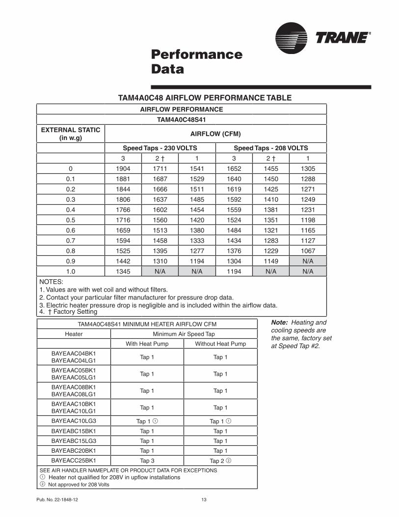
TAM4A0C48 AIRFLOW PERFORMANCE TABLEAIRFLOW PERFORMANCE
TAM4A0C48S41
EXTERNAL STATIC (in w.g)
AIRFLOW (CFM)
Speed Taps - 230 VOLTS Speed Taps - 208 VOLTS
3 2 † 1 3 2 † 1
0 1904 1711 1541 1652 1455 1305
0.1 1881 1687 1529 1640 1450 1288
0.2 1844 1666 1511 1619 1425 1271
0.3 1806 1637 1485 1592 1410 1249
0.4 1766 1602 1454 1559 1381 1231
0.5 1716 1560 1420 1524 1351 1198
0.6 1659 1513 1380 1484 1321 1165
0.7 1594 1458 1333 1434 1283 1127
0.8 1525 1395 1277 1376 1229 1067
0.9 1442 1310 1194 1304 1149 N/A
1.0 1345 N/A N/A 1194 N/A N/A
NOTES:1. Values are with wet coil and without filters.2. Contact your particular filter manufacturer for pressure drop data. 3. Electric heater pressure drop is negligible and is included within the airflow data.4. † Factory Setting
Note: Heating and cooling speeds are the same, factory set at Speed Tap #2.
TAM4A0C48S41 MINIMUM HEATER AIRFLOW CFM
Heater Minimum Air Speed Tap
With Heat Pump Without Heat Pump
BAYEAAC04BK1 BAYEAAC04LG1
Tap 1 Tap 1
BAYEAAC05BK1 BAYEAAC05LG1
Tap 1 Tap 1
BAYEAAC08BK1 BAYEAAC08LG1
Tap 1 Tap 1
BAYEAAC10BK1 BAYEAAC10LG1
Tap 1 Tap 1
BAYEAAC10LG3 Tap 1 1 Tap 1 1
BAYEABC15BK1 Tap 1 Tap 1
BAYEABC15LG3 Tap 1 Tap 1
BAYEABC20BK1 Tap 1 Tap 1
BAYEACC25BK1 Tap 3 Tap 2 2
SEE AIR HANDLER NAMEPLATE OR PRODUCT DATA FOR EXCEPTIONS1 Heater not qualified for 208V in upflow installations2 Not approved for 208 Volts
14 Pub. No. 22-1848-12
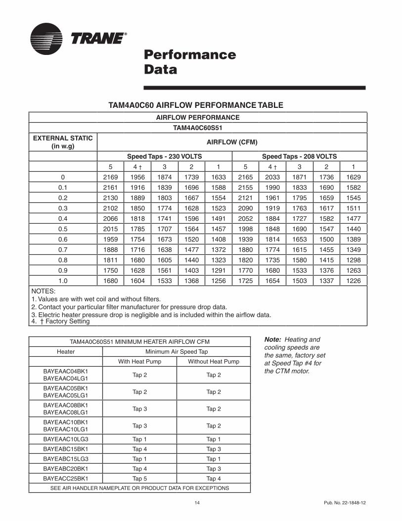
TAM4A0C60 AIRFLOW PERFORMANCE TABLE
PerformanceData
AIRFLOW PERFORMANCE
TAM4A0C60S51
EXTERNAL STATIC (in w.g)
AIRFLOW (CFM)
Speed Taps - 230 VOLTS Speed Taps - 208 VOLTS
5 4 † 3 2 1 5 4 † 3 2 1
0 2169 1956 1874 1739 1633 2165 2033 1871 1736 1629
0.1 2161 1916 1839 1696 1588 2155 1990 1833 1690 1582
0.2 2130 1889 1803 1667 1554 2121 1961 1795 1659 1545
0.3 2102 1850 1774 1628 1523 2090 1919 1763 1617 1511
0.4 2066 1818 1741 1596 1491 2052 1884 1727 1582 1477
0.5 2015 1785 1707 1564 1457 1998 1848 1690 1547 1440
0.6 1959 1754 1673 1520 1408 1939 1814 1653 1500 1389
0.7 1888 1716 1638 1477 1372 1880 1774 1615 1455 1349
0.8 1811 1680 1605 1440 1323 1820 1735 1580 1415 1298
0.9 1750 1628 1561 1403 1291 1770 1680 1533 1376 1263
1.0 1680 1604 1533 1368 1256 1725 1654 1503 1337 1226
NOTES:1. Values are with wet coil and without filters.2. Contact your particular filter manufacturer for pressure drop data. 3. Electric heater pressure drop is negligible and is included within the airflow data.4. † Factory Setting
Note: Heating and cooling speeds are the same, factory set at Speed Tap #4 for the CTM motor.
TAM4A0C60S51 MINIMUM HEATER AIRFLOW CFM
Heater Minimum Air Speed Tap
With Heat Pump Without Heat Pump
BAYEAAC04BK1 BAYEAAC04LG1
Tap 2 Tap 2
BAYEAAC05BK1 BAYEAAC05LG1
Tap 2 Tap 2
BAYEAAC08BK1 BAYEAAC08LG1
Tap 3 Tap 2
BAYEAAC10BK1 BAYEAAC10LG1
Tap 3 Tap 2
BAYEAAC10LG3 Tap 1 Tap 1
BAYEABC15BK1 Tap 4 Tap 3
BAYEABC15LG3 Tap 1 Tap 1
BAYEABC20BK1 Tap 4 Tap 3
BAYEACC25BK1 Tap 5 Tap 4
SEE AIR HANDLER NAMEPLATE OR PRODUCT DATA FOR EXCEPTIONS

Pub. No. 22-1848-12 15
ElectricalData
WIRING DATA
TAM4A0A18S11
Heater Model
No.
No. of
Circuits
240 VOLT 208 VOLT
CapacityHeater Amps
per Circuit
Minimum Circuit
Ampacity
Maximum Overload
Protection
CapacityHeater Amps
per Circuit
Minimum Circuit
Ampacity
Maximum Overload
ProtectionkW BTUH kW BTUH
No Heater - - - 2.0** 3 15 - - 2.0** 3 15
BAYEAAC04++1 1 3.84 13100 16 23 25 2.88 9800 13.80 20 20
BAYEAAC05++1 1 4.80 16400 20 28 30 3.60 12300 17.30 24 25
BAYEAAC08++1 1 7.68 26200 32 43 45 5.76 19700 27.70 37 40
BAYEAAC10++1 1 9.60 32800 40 53 60 7.20 24600 34.60 46 50
BAYEAAC10LG3 1-3PH 9.60 32800 23.1 31 35 7.20 24600 20.00 27 30
Note: ** Motor Amps
WIRING DATA
TAM4A0A24S21
Heater Model
No.
No. of
Circuits
240 VOLT 208 VOLT
CapacityHeater Amps
per Circuit
Minimum Circuit
Ampacity
Maximum Overload
Protection
CapacityHeater Amps
per Circuit
Minimum Circuit
Ampacity
Maximum Overload
ProtectionkW BTUH kW BTUH
No Heater - - - 1.3** 2 15 - - 1.3** 2 15
BAYEAAC04++1 1 3.84 13100 16 22 25 2.88 9800 13.80 19 20
BAYEAAC05++1 1 4.80 16400 20 27 30 3.60 12300 17.30 23 25
BAYEAAC08++1 1 7.68 26200 32 42 45 5.76 19700 27.70 36 40
BAYEAAC10++11 1 9.60 32800 40 52 60 7.20 24600 34.60 45 45
BAYEAAC10LG3 1-3PH 9.60 32800 23.1 30 30 7.20 24600 20.00 26 30
Note: ** Motor Amps1 For heat pump, minimum Speed Tap is 3 for Horizontal Left only.

16 Pub. No. 22-1848-12
ElectricalData
Notes:1. See Air Handler Nameplate for approved combinations of Air Handlers and Heaters.2. Heater model number may have additional suffix digits.
WIRING DATA
TAM4A0A30S21
Heater Model
No.
No. of
Circuits
240 VOLT 208 VOLT
CapacityHeater Amps
per Circuit
Minimum Circuit
Ampacity
Maximum Overload
Protection
CapacityHeater Amps
per Circuit
Minimum Circuit
Ampacity
Maximum Overload
ProtectionkW BTUH kW BTUH
No Heater - - - 1.7** 2 15 - - 1.7** 2 15
BAYEAAC04++1 1 3.84 13100 16 22 25 2.88 9800 13.80 19 20
BAYEAAC05++1 1 4.80 16400 20 27 30 3.60 12300 17.3 24 25
BAYEAAC08++1 1 7.68 26200 32 42 45 5.76 19700 27.7 37 40
BAYEAAC10++1 1 9.60 32800 40 52 60 7.20 24600 34.6 45 45
BAYEAAC10LG3 1-3PH 9.60 32800 23.1 31 35 7.20 24600 20.00 27 30
BAYEABC15LG3 1 1-3PH 14.40 49200 34.6 45 45 10.80 36900 30.00 39 40
BAYEABC15++1 2
circuit 1 9.60 32800 40 52 60 7.20 24600 34.6 45 45
circuit 2 4.80 16400 20 25 25 3.60 12300 17.3 22 25
Note: ** Motor Amps1 Heater not qualified for 240V in downflow installations.
WIRING DATA
TAM4A0A36S31
Heater Model
No.
No. of
Circuits
240 VOLT 208 VOLT
CapacityHeater Amps
per Circuit
Minimum Circuit
Ampacity
Maximum Overload
Protection
CapacityHeater Amps
per Circuit
Minimum Circuit
Ampacity
Maximum Overload
ProtectionkW BTUH kW BTUH
No Heater - - - 2.4** 3 15 - - 2.4** 3 15
BAYEAAC04++1 1 3.84 13100 16 23 25 2.88 9800 13.80 20 20
BAYEAAC05++1 1 4.80 16400 20 28 30 3.60 12300 17.3 25 25
BAYEAAC08++1 1 1 7.68 26200 32 43 45 5.76 19700 27.7 38 40
BAYEAAC10++1 2 1 9.60 32800 40 53 60 N/A 2 N/A 2 N/A 2 N/A 2 N/A 2
BAYEAAC10LG3 1-3PH 9.60 32800 23.1 32 35 7.20 24600 20.0 28 30
BAYEABC15LG3 1-3PH 14.40 49200 34.6 46 50 10.80 36900 30.0 40 40
BAYEABC15++1 2
circuit 1 9.60 32800 40 53 60 7.20 24600 34.6 46 50
circuit 2 4.80 16400 20 25 25 3.60 12300 17.3 22 25
Note: ** Motor Amps1 Heater not approved for Horizontal Left installations. Upflow Installation approved for 240 Volts only.2 Approved for 240 Volts only. Approved for Upflow only.

Pub. No. 22-1848-12 17
Notes:1. See Air Handler Nameplate for approved combinations of Air Handlers and Heaters.2. Heater model number may have additional suffix digits.
ElectricalData
WIRING DATA
TAM4A0B42S31
Heater Model
No.
No. of
Circuits
240 VOLT 208 VOLT
CapacityHeater Amps
per Circuit
Minimum Circuit
Ampacity
Maximum Overload
Protection
CapacityHeater Amps
per Circuit
Minimum Circuit
Ampacity
Maximum Overload
ProtectionkW BTUH kW BTUH
No Heater - - - 2.7** 3 15 - - 2.7** 3 15
BAYEAAC04++1 1 3.84 13100 16 23 25 2.88 9800 13.80 21 25
BAYEAAC05++1 1 4.80 16400 20 28 30 3.60 12300 17.3 25 25
BAYEAAC08++1 1 7.68 26200 32 43 45 5.76 19700 27.7 38 40
BAYEAAC10++1 1 9.60 32800 40 53 60 7.20 24600 34.6 47 50
BAYEAAC10LG3 1-3PH 9.60 32800 23.1 32 35 7.20 24600 20.0 28 30
BAYEABC15LG31 1-3PH 14.40 49200 34.6 46 50 10.80 36900 30.0 40 40
BAYEABC15++1 2
circuit 1 9.60 32800 40 53 60 7.20 24600 34.6 47 50
circuit 2 4.80 16400 20 25 25 3.60 12300 17.3 22 25
BAYEABC20++1 2
circuit 1 9.60 32800 40 53 60 7.20 24600 34.6 53 60
circuit 2 9.60 32800 40 50 50 7.20 24600 34.6 43 45
Note: ** Motor Amps1 Heater not qualified for 240V in downflow installations
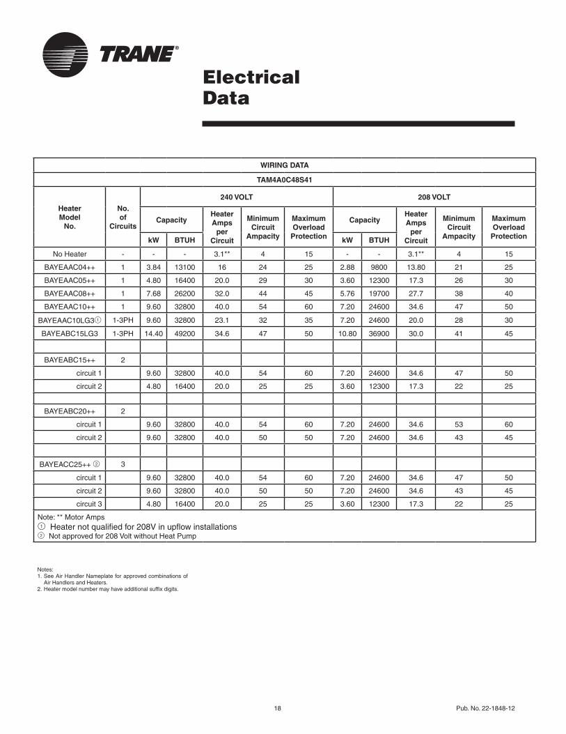
18 Pub. No. 22-1848-12
ElectricalData
Notes:1. See Air Handler Nameplate for approved combinations of
Air Handlers and Heaters.2. Heater model number may have additional suffix digits.
WIRING DATA
TAM4A0C48S41
Heater Model
No.
No. of
Circuits
240 VOLT 208 VOLT
CapacityHeater Amps
per Circuit
Minimum Circuit
Ampacity
Maximum Overload
Protection
CapacityHeater Amps
per Circuit
Minimum Circuit
Ampacity
Maximum Overload
ProtectionkW BTUH kW BTUH
No Heater - - - 3.1** 4 15 - - 3.1** 4 15
BAYEAAC04++ 1 3.84 13100 16 24 25 2.88 9800 13.80 21 25
BAYEAAC05++ 1 4.80 16400 20.0 29 30 3.60 12300 17.3 26 30
BAYEAAC08++ 1 7.68 26200 32.0 44 45 5.76 19700 27.7 38 40
BAYEAAC10++ 1 9.60 32800 40.0 54 60 7.20 24600 34.6 47 50
BAYEAAC10LG31 1-3PH 9.60 32800 23.1 32 35 7.20 24600 20.0 28 30
BAYEABC15LG3 1-3PH 14.40 49200 34.6 47 50 10.80 36900 30.0 41 45
BAYEABC15++ 2
circuit 1 9.60 32800 40.0 54 60 7.20 24600 34.6 47 50
circuit 2 4.80 16400 20.0 25 25 3.60 12300 17.3 22 25
BAYEABC20++ 2
circuit 1 9.60 32800 40.0 54 60 7.20 24600 34.6 53 60
circuit 2 9.60 32800 40.0 50 50 7.20 24600 34.6 43 45
BAYEACC25++ 2 3
circuit 1 9.60 32800 40.0 54 60 7.20 24600 34.6 47 50
circuit 2 9.60 32800 40.0 50 50 7.20 24600 34.6 43 45
circuit 3 4.80 16400 20.0 25 25 3.60 12300 17.3 22 25
Note: ** Motor Amps1 Heater not qualified for 208V in upflow installations2 Not approved for 208 Volt without Heat Pump

Pub. No. 22-1848-12 19
Notes:1. See Air Handler Nameplate for approved combinations of
Air Handlers and Heaters.2. Heater model number may have additional suffix digits.
ElectricalData
WIRING DATA
TAM4A0C60S51
Heater Model
No.
No. of
Circuits
240 VOLT 208 VOLT
CapacityHeater Amps
per Circuit
Minimum Circuit
Ampacity
Maximum Overload
Protection
CapacityHeater Amps
per Circuit
Minimum Circuit
Ampacity
Maximum Overload
ProtectionkW BTUH kW BTUH
No Heater - - - 7.6** 10 15 - - 7.6** 10 15
BAYEAAC04++ 1 3.84 13100 16 30 30 2.88 9800 13.80 27 30
BAYEAAC05++ 1 4.80 16400 20.0 35 35 3.60 12300 17.3 31 35
BAYEAAC08++ 1 7.68 26200 32.0 50 50 5.76 19700 27.7 44 45
BAYEAAC10++ 1 9.60 32800 40.0 60 60 7.20 24600 34.6 53 60
BAYEAAC10LG3 1-3PH 9.60 32800 23.1 37 40 7.20 24600 20.0 34 35
BAYEABC15LG3 1-3PH 14.40 49200 34.6 52 60 10.80 36900 30.0 46 50
BAYEABC15++ 2
circuit 1 9.60 32800 40.0 60 60 7.20 24600 34.6 53 60
circuit 2 4.80 16400 20.0 25 25 3.60 12300 17.3 22 25
BAYEABC20++ 2
circuit 1 9.60 32800 40.0 60 60 7.20 24600 34.6 53 60
circuit 2 9.60 32800 40.0 50 50 7.20 24600 34.6 43 45
BAYEACC25++ 3
circuit 1 9.60 32800 40.0 60 60 7.20 24600 34.6 53 60
circuit 2 9.60 32800 40.0 50 50 7.20 24600 34.6 43 45
circuit 3 4.80 16400 20.0 25 25 3.60 12300 17.3 22 25
Note: ** Motor Amps
20 Pub. No. 22-1848-12
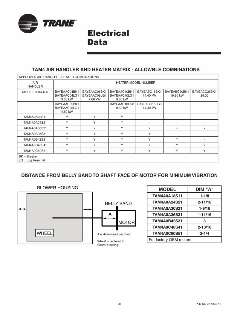
TAM4 AIR HANDLER AND HEATER MATRIX - ALLOWBLE COMBINATIONS
ElectricalData
DISTANCE FROM BELLY BAND TO SHAFT FACE OF MOTOR FOR MINIMUM VIBRATION
WHEEL
BLOWER HOUSING
BELLY BAND
MOTOR
A
A is determined per chart
Wheel is centered inBlower Housing
MODEL DIM "A"TAM4A0A18S11 1-1/8
TAM4A0A24S21 2-11/16
TAM4A0A30S21 1-9/16
TAM4A0A36S31 1-11/16
TAM4A0B42S31 3
TAM4A0C48S41 2-13/16
TAM4A0C60S51 2-1/4
For factory OEM motors
APPROVED AIR HANDLER - HEATER COMBINATIONS
AIR HANDLER
HEATER MODEL NUMBER
MODEL NUMBER BAYEAAC04BK1BAYEAAC04LG1
3.68 kW
BAYEAAC08BK1 BAYEAAC08LG1
7.68 kW
BAYEAAC10BK1BAYEAAC10LG1
9.60 kW
BAYEABC15BK114.40 kW
BAYEABC20BK119.20 kW
BAYEACC25BK124.00
BAYEAAC05BK1BAYEAAC05LG1
4.80 kW
BAYEAAC10LG39.60 kW
BAYEABC15LG314.40 kW
TAM4A0A18S11 Y Y Y - - -
TAM4A0A24S21 Y Y Y - - -
TAM4A0A30S21 Y Y Y Y - -
TAM4A0A36S31 Y Y Y Y - -
TAM4A0B42S31 Y Y Y Y Y -
TAM4A0C48S41 Y Y Y Y Y Y
TAM4A0C60S51 Y Y Y Y Y Y
BK = BreakerLG = Lug Terminal
Pub. No. 22-1848-12 21
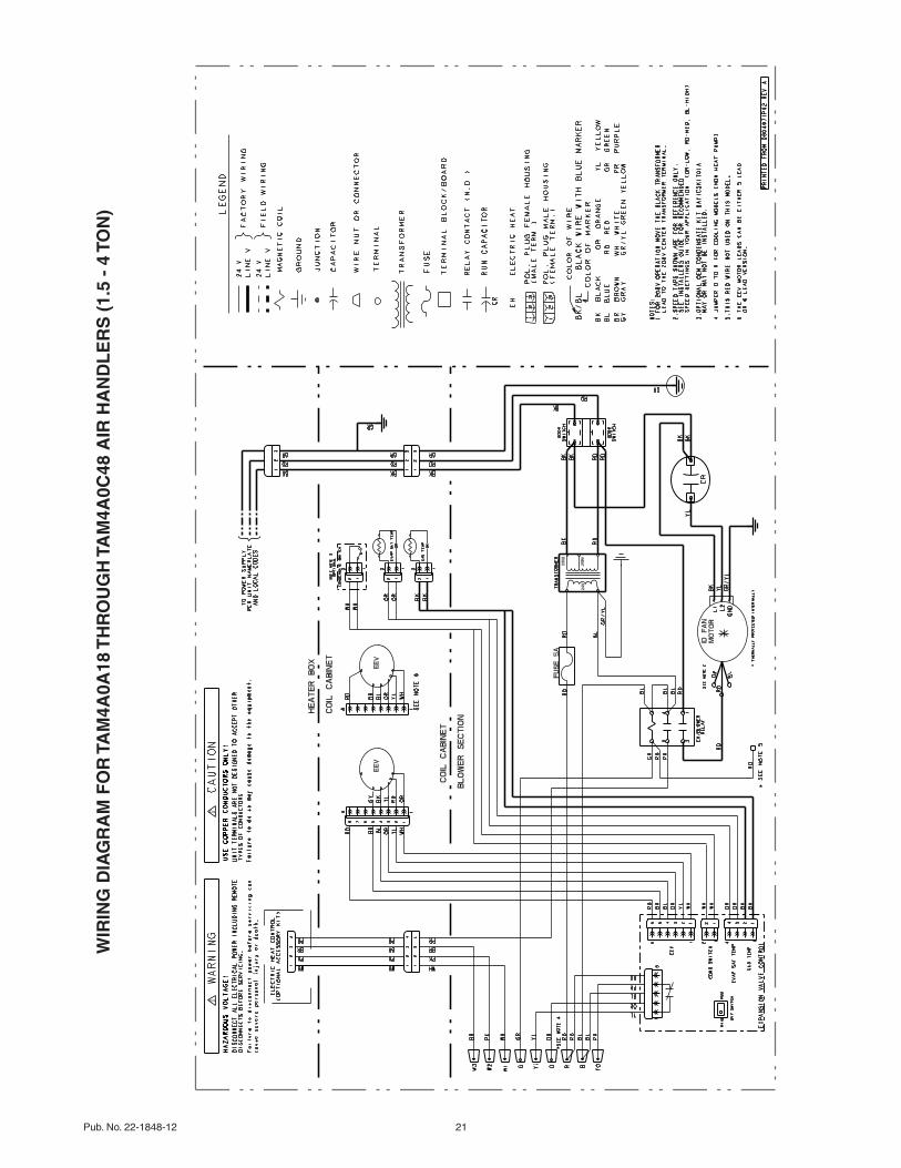
WIR
ING
DIA
GR
AM
FO
R T
AM
4A0A
18 T
HR
OU
GH
TA
M4A
0C48
AIR
HA
ND
LE
RS
(1.
5 -
4 TO
N)
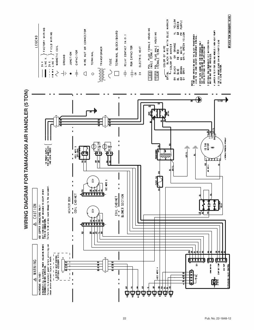
22 Pub. No. 22-1848-12
WIR
ING
DIA
GR
AM
FO
R T
AM
4A0C
60 A
IR H
AN
DL
ER
(5
TON
)
Pub. No. 22-1848-12 23
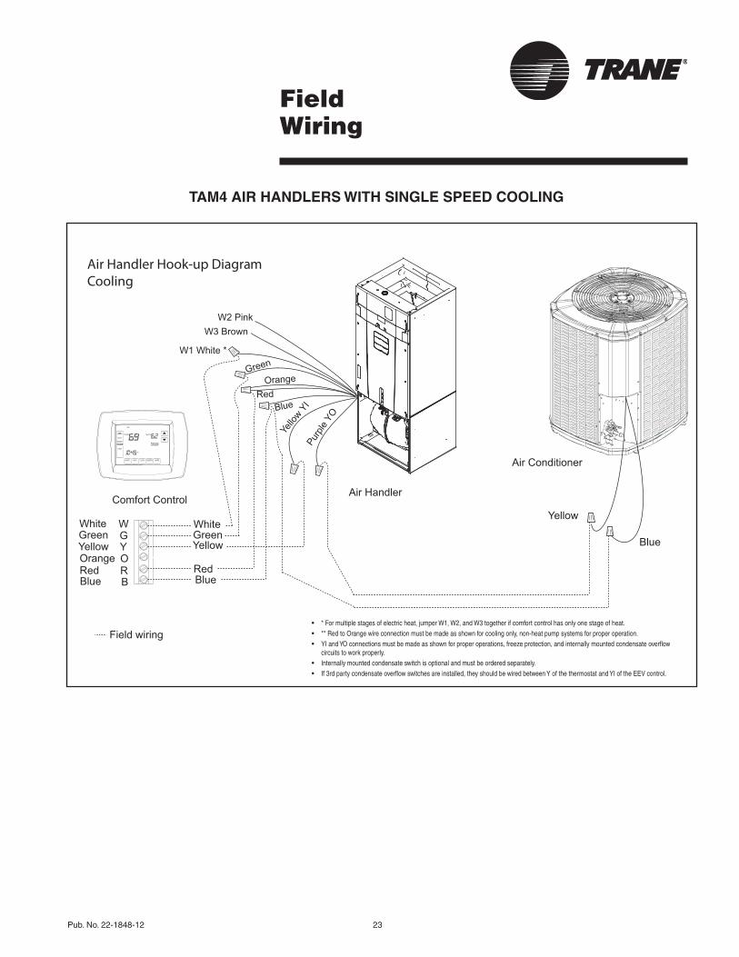
FieldWiring
TAM4 AIR HANDLERS WITH SINGLE SPEED COOLING
Air Handler Hook-up DiagramCooling
Blue
YellowComfort Control
Air Handler
Air Conditioner
Field wiring
Red
YellowGreenWhite
Blue
YellowGreenWhite
Blue B
WGY
RRedOOrange
RedOrange
Blue
Yello
w YI
Purp
le YO
Green
W2 PinkW3 Brown
W1 White *
• * For multiple stages of electric heat, jumper W1, W2, and W3 together if comfort control has only one stage of heat. • ** Red to Orange wire connection must be made as shown for cooling only, non-heat pump systems for proper operation. • YI and YO connections must be made as shown for proper operations, freeze protection, and internally mounted condensate overflow
circuits to work properly. • Internally mounted condensate switch is optional and must be ordered separately. • If 3rd party condensate overflow switches are installed, they should be wired between Y of the thermostat and YI of the EEV control.

24 Pub. No. 22-1848-12
FieldWiring
TAM4 AIR HANDLERS WITH SINGLE SPEED HEAT PUMP
Air Handler Hook-up DiagramHeat Pump
Comfort Control
Field wiring
YellowGreenWhite
Blue B
WGY
RRedOOrange
Yellow
Blue
Black(X2)
Red
Orange
Heat Pump
B - Blue
Y - Yellow
R - Red
O - Orange
W1 - White
Air Handler
Red
Blue
Yello
w Y
I
Purp
le Y
O
Ora
nge
Green
W2 PinkW3 Brown
W1 White *
• * For multiple stages of electric heat, jumper W1, W2, and W3 together if comfort control has only one stage of heat • YI and YO connections must be made as shown for proper operation, freeze protection, and internally mounted condensate
overflow circuits to work properly • Internally mounted condensate switch is optional and must be ordered separately • If a 3rd party condensate overflow switch is installed, it should be wired between Y of the thermostat and YI of the EEV control.
Pub. No. 22-1848-12 25
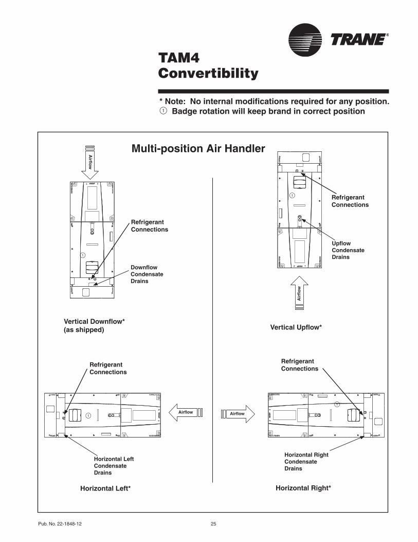
TAM4Convertibility
* Note: No internal modifications required for any position.1 Badge rotation will keep brand in correct position
Multi-position Air Handler
Airflo
w
AirflowAirflow
Air
flo
w
Upflow Condensate Drains
Refrigerant Connections
Downflow Condensate Drains
Refrigerant Connections
Vertical Downflow*(as shipped)
Horizontal Left*
Vertical Upflow*
Horizontal Right*
Horizontal Left Condensate Drains
Refrigerant Connections
Horizontal Right Condensate Drains
Refrigerant Connections
1
1
1
1

26 Pub. No. 22-1848-12
Dimensions
TAM4 AIR HANDLER DIMENSIONAL DATA
Model No. H W
TAM4A0A18 49.9 17.5
TAM4A0A24 49.9 17.5
TAM4A0A30 49.9 17.5
TAM4A0A36 49.9 17.5
TAM4A0B42 55.7 21.3
TAM4A0C48 56.9 23.5
TAM4A0C60 61.7 23.5
TAM4 AIR HANDLERS ARE ALL TWO PIECE CABINETS.
D
H
W
Pub. No. 22-1848-12 27
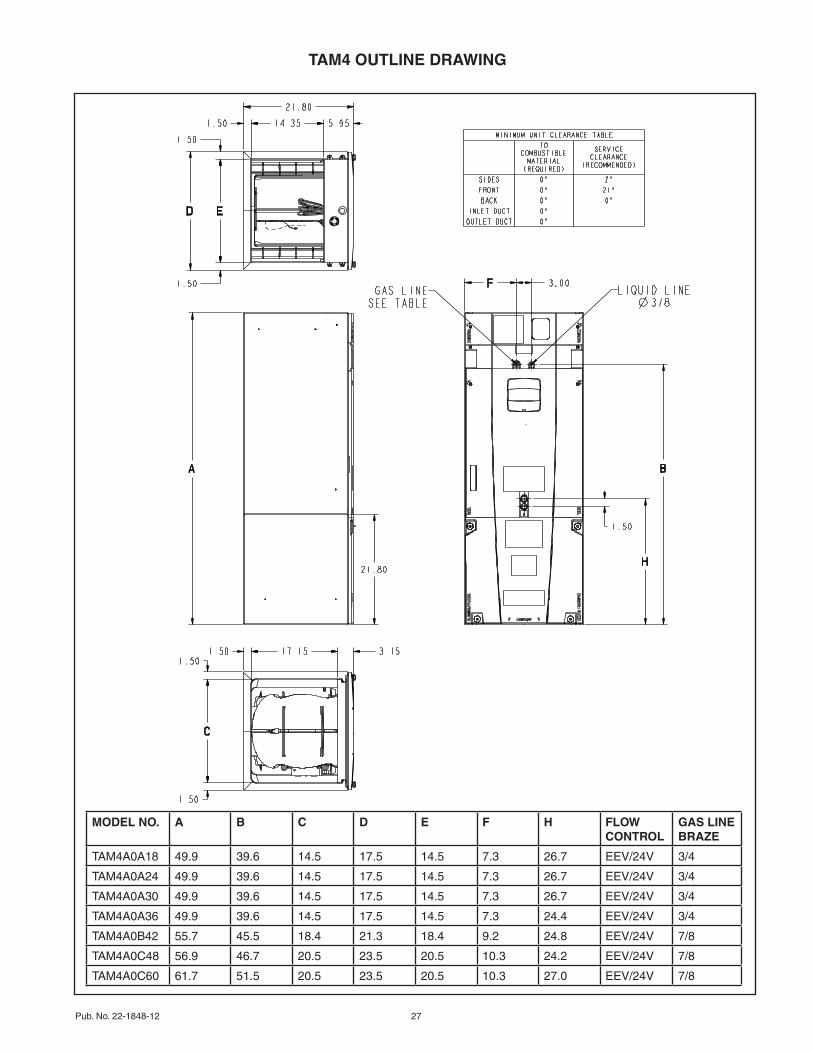
TAM4 OUTLINE DRAWING
MODEL NO. A B C D E F H FLOW CONTROL
GAS LINE BRAZE
TAM4A0A18 49.9 39.6 14.5 17.5 14.5 7.3 26.7 EEV/24V 3/4
TAM4A0A24 49.9 39.6 14.5 17.5 14.5 7.3 26.7 EEV/24V 3/4
TAM4A0A30 49.9 39.6 14.5 17.5 14.5 7.3 26.7 EEV/24V 3/4
TAM4A0A36 49.9 39.6 14.5 17.5 14.5 7.3 24.4 EEV/24V 3/4
TAM4A0B42 55.7 45.5 18.4 21.3 18.4 9.2 24.8 EEV/24V 7/8
TAM4A0C48 56.9 46.7 20.5 23.5 20.5 10.3 24.2 EEV/24V 7/8
TAM4A0C60 61.7 51.5 20.5 23.5 20.5 10.3 27.0 EEV/24V 7/8

Trane6200 Troup HighwayTyler, TX 75707www.trane.com
03/16
The manufacturer has a policy of continuous product and product data improvement and it reserves the right to change design and specifications without notice.