MODU Mooring in Australian Tropical Waters … Mooring in Australian Tropical Waters Guidelines Page...
55
MODU Mooring in Australian Tropical Waters Guideline Revision 1 | 01/04/17
Transcript of MODU Mooring in Australian Tropical Waters … Mooring in Australian Tropical Waters Guidelines Page...

MODU Mooring
in Australian Tropical Waters
Guideline
Revision 1 | 01/04/17

MODU Mooring in Australian Tropical Waters Guidelines Page 2 of 55
PREFACE
This guideline has been developed by industry to provide a consistent and common approach to MODU
mooring exposed to cyclonic conditions in Australian tropical waters. Industry participants include Oil & Gas
Operators through APPEA drilling industry steering group (DISC), MODU mooring contractors through
International Association of Drilling Contractors (IADC) and mooring equipment and engineering contractors.
The guideline is to be read in conjunction with the NOPSEMA information paper MODU Mooring systems in
cyclonic conditions [10], company mooring standards and procedures and well known industry codes (API,
DNV etc.).
DISCLAIMER
APPEA and its participants disclaim any liability of whatsoever nature for any damage (including injury or
death) suffered by any company or person whomsoever as a result of or in connection with the use,
application or implementation of this guideline or any part there of contained in this document.
CONTRIBUTORS
The authors would like to acknowledge the industry contributors who were instrumental in writing this
Guideline:
Woodside
Inpex
Chevron
Quadrant Energy
Shell
Transocean
Stena Drilling
Atwood Oceanics
Delmar Systems
Viking Seatech
Deep Sea Moorings
DNV-GL
Evan Zimmerman (TechnoNautic)
REVIEW & UPDATES
This publication is intended to be ‘living‘, working document with feedback welcomed and incorporated into a
regular review process and the guidelines updated where necessary or desirable.
A feedback form to the editorial committee to provide comments, suggestions for additions or changes or new information on the document can be found in Appendix F.

MODU Mooring in Australian Tropical Waters Guidelines Page 3 of 55
TABLE OF CONTENTS
1 DEFINITIONS AND ABBREVIATIONS .................................................................................................. 6
A1 Definitions ................................................................................................................................................ 6
A2 Abbreviations ........................................................................................................................................... 7
A3 Use of Language ...................................................................................................................................... 8
2 INTRODUCTION ..................................................................................................................................... 9
2.1 How to use this document ....................................................................................................................... 9
2.2 Supporting Mooring Codes and Standards ........................................................................................... 11
3 RISK SCREENING ................................................................................................................................ 12
3.1 Introduction ............................................................................................................................................ 12
3.2 Philosophy of risk screening .................................................................................................................. 12
3.3 Risk Screening Tests ............................................................................................................................. 12
3.4 MODU Mooring Risk Category .............................................................................................................. 13
4 RISK & ASSURANCE MANAGEMENT ................................................................................................ 14
4.1 Introduction ............................................................................................................................................ 14
4.2 Principles ............................................................................................................................................... 14
4.3 Objectives .............................................................................................................................................. 14
4.4 Risk Assessment ................................................................................................................................... 14
4.5 Risk Evaluation ...................................................................................................................................... 15
4.6 Risk Treatment ....................................................................................................................................... 16
4.7 Risk Based Mitigation Activities ............................................................................................................. 17
5 MOORING DESIGN & ANALYSIS ........................................................................................................ 18
5.1 Basis of Design Requirements .............................................................................................................. 18
5.2 Mooring Design Scope of Work ............................................................................................................. 19
5.3 Metocean Return Period Criteria ........................................................................................................... 21
5.4 Risk Based Mitigation Activities ............................................................................................................. 22
6 METOCEAN .......................................................................................................................................... 23
6.1 Salient Oceanographic Features ........................................................................................................... 23
6.2 Synoptic Meteorology ............................................................................................................................ 23
6.3 Winter Season ....................................................................................................................................... 23
6.4 Summer Season .................................................................................................................................... 23
6.5 The Transition Seasons ......................................................................................................................... 23
6.6 Extreme Wind Conditions ...................................................................................................................... 24
6.7 Easterly Gales (Trade Wind Surge) ....................................................................................................... 24
6.8 Tropical Cyclones .................................................................................................................................. 24
6.9 Squalls ................................................................................................................................................... 24
6.10 Wave Climatology .................................................................................................................................. 24
6.11 Current Regime ...................................................................................................................................... 25
6.12 Temperature and Salinity Distributions .................................................................................................. 25
6.13 Tidal range ............................................................................................................................................. 25
6.14 Risk Based Mitigation Activities ............................................................................................................. 26
7 GEOTECHNICAL .................................................................................................................................. 27
7.1 Geology of the NWATW of Australia and Geohazards .......................................................................... 27
7.2 Estimating anchor capacity in calcareous soils ..................................................................................... 27
7.3 Anchor installation and testing requirements ......................................................................................... 28

MODU Mooring in Australian Tropical Waters Guidelines Page 4 of 55
7.4 Sharing geotechnical information .......................................................................................................... 28
7.5 Risk Based Mitigation Activities ............................................................................................................. 29
8 MOORING EQUIPMENT ....................................................................................................................... 30
8.1 Scope ..................................................................................................................................................... 30
8.2 Manufacturing, Testing & Certification ................................................................................................... 30
8.3 Equipment Storage ................................................................................................................................ 30
8.4 Maintenance & Service History .............................................................................................................. 30
8.5 Use of Fibre Mooring Lines .................................................................................................................... 31
8.6 Risk Based Mitigation Activities ............................................................................................................. 32
9 MOORING INSPECTION ...................................................................................................................... 33
9.1 Scope ..................................................................................................................................................... 33
9.2 Equipment Inspection Standards & Procedures .................................................................................... 33
9.3 Inspector Competence & Training ......................................................................................................... 33
9.4 Chain, Accessories & Wire Rope Visual Inspection .............................................................................. 33
9.5 Chain, Accessories & Wire Rope Magnetic Particle Inspection ............................................................ 34
9.6 Fibre Rope Inspection ............................................................................................................................ 35
9.7 Wire Rope Sockets ................................................................................................................................ 35
9.8 Fibre Rope Eye Splice ........................................................................................................................... 35
9.9 Pre & Post Tropical Cyclone Inspection Requirements ......................................................................... 36
9.10 Risk Based Mitigation Activities ............................................................................................................. 37
10 MOORING OPERATIONS .................................................................................................................... 38
10.1 Scope ..................................................................................................................................................... 38
10.2 Operations Standards & Procedures ..................................................................................................... 38
10.3 Vessel and MODU Personnel Competence & Training ......................................................................... 38
10.4 Mooring System Rigging and Handling ................................................................................................. 38
10.5 Mooring Installation & Recovery Procedures ........................................................................................ 39
10.6 Marine Operations ................................................................................................................................. 40
10.7 Tropical Cyclone Preparation & Response ............................................................................................ 40
10.8 Risk Based Mitigation Activities ............................................................................................................. 42
REFERENCES ................................................................................................................................................. 43
APPENDIX A: MODU MOORING SYSTEM PERFORMANCE STANDARD ................................................. 44
APPENDIX B: MODU CYCLONE PREPARATION CHECKLIST .................................................................. 48
APPENDIX C: MODU MOORING FAILURE FLOW CHART ......................................................................... 50
APPENDIX D: EXAMPLE MOORING BASIS OF DESIGN FORM ................................................................ 51
APPENDIX E: MODU MOORING WORKFLOW GUIDANCE ........................................................................ 52
Step 1 – Collect information ............................................................................................................................. 52
Step 2 – Determine MODU mooring risk category .......................................................................................... 53
Step 3 – Review Risk Mitigation Measures and determine metocean Return Period ..................................... 53
Step 4 – Conduct Mooring Analysis ................................................................................................................. 54
Step 5 – Conduct Risk Assessment ................................................................................................................. 54
APPENDIX F: FEEDBACK FORM .................................................................................................................. 55

MODU Mooring in Australian Tropical Waters Guidelines Page 5 of 55
DOCUMENT REVISION HISTORY
REVIEW STATUS
DETAILED REVISION INFORMATION
Revision Description Date Prepared by Approved by
A Split document review by Block 1 & 2 Groups 10/06/16 APPEA DISC APPEA DISC
B Compiled document review by TechnoNautic,
Block 1, Block 2 & DNVGL.
08/07/16 APPEA DISC APPEA DISC
0 Final approved version 01/11/16 APPEA DISC APPEA DISC
1 Feedback Form added as Appendix F 1/04/16 APPEA DISC APPEA DISC

MODU Mooring in Australian Tropical Waters Guidelines Page 6 of 55
1 DEFINITIONS AND ABBREVIATIONS
A1 Definitions
Term Definition
Close Proximity Refers to distance between the MODU and surface and/or subsea
assets, including areas of environmental significance, which are
close enough to be considered a mooring risk. The risk depends
on the type/value/manning of asset as well as MODU mooring
design certainty and equipment assurance. The distance depends
on the mooring risk and company risk tolerance. As a rule of
thumb a distance between MODU mooring centre and high value
asset of 10km–20km may be considered “Close Proximity”.
Limit State Analysis Relationship between metocean data return period and mooring
factor of safety. The purpose of this data is to estimate the return
period (in years) corresponding to mooring failure.
Operator Operator of the MODU as per NOPSEMA definition.
Titleholder Holder of the exploration or production permit as per NOPSEMA
definition.

MODU Mooring in Australian Tropical Waters Guidelines Page 7 of 55
A2 Abbreviations
Abbreviation Definition
ALARP As Low As Reasonably Practical
API American Petroleum Institute
APPEA Australian Petroleum Production & Exploration Association
BOD Basis of Design
BOE/D Barrels of Oil Equivalent per Day
BOM Bureau of Meteorology
BOP Blow Out Preventer
CPT Cone Penetration Test
DISC Drilling Industry Steering Committee
DNV GL Det Norske Veritas Germanische Lloyd
FOS Factor of Safety
GOMO Guidelines for Offshore Marine Operations
IACS International Association of Classification Societies
IADC International Association of Drilling Contractors
ICAP Inspection & Condition Assessment Plan
ISO International Standards Organisation
JIP Joint Industry Project
MAE Major Accident Event
MMATW MODU Mooring in Australian Tropical Waters
MOC Management of Change
MODU Mobile Offshore Drilling Unit
MBL Minimum Breaking Load
MBS Minimum Breaking Strength
MPI Magnetic Particle Inspection
NDT Non Destructive Testing
NGI Norwegian Geotechnical Institute
NOPSEMA National Offshore Petroleum Safety & Environmental Management Authority
NWATW North West Australian Tropical Waters

MODU Mooring in Australian Tropical Waters Guidelines Page 8 of 55
OEM Original Equipment Manufacturer
OPGGS(S) Offshore Petroleum and Greenhouse Gas Storage (Safety)
OSIG Offshore Site Investigation and Geotechnics
PCC Permanent Chain Chaser
PCP Permanent Chain Pendent
PMS Planned Maintenance System
QAQC Quality Assurance & Quality Control
QRA Quantitative Risk Assessment
RAO Response Amplitude Operator
RCS Recognised Classification Society
RP Return Period
ROV Remotely Operated Vehicle
SLF Single Line Failure
SUT Society for Underwater Technology
UHC Ultimate Holding Capacity
UV Ultra-Violet
A3 Use of Language
Term Definition
Consider Refers to risk based mitigation activities identified in this guideline
that may be applied when implementing this guideline.
Recommended Refers to risk based mitigation activities identified in this guideline
that ought to be applied when implementing this guideline.
Highly Recommended Refers to risk based mitigation activities identified in this guideline
that ought be applied when implementing this guideline.
Justification should be documented where the recommended
activity is not adopted.
May Compliance is discretionary and is to be considered.
Should Compliance is discretionary but is recommended.
Shall/Must Compliance with the requirement is mandatory.

MODU Mooring in Australian Tropical Waters Guidelines Page 9 of 55
2 INTRODUCTION
Described below is guidance on MODU mooring in Australian tropical waters (MMATW). Due to a loss of
station keeping event to a MODU in 2015, and in response to the investigation and NOPSEMA collaboration,
APPEA has agreed to produce and publish this guideline to provide greater clarity on mooring a MODU in
cyclonic conditions in Australian tropical waters. The purpose of this document is to:
Provide a consistent approach to mooring design, installation and equipment assurance.
A framework to improving station keeping reliability and performance in local conditions which are
unique to this region.
2.1 How to use this document
This document is intended to be read in conjunction with industry standards, codes and recommended
practices such as API and DNV and company standards (if applicable).
The document provides recommendations and guidance on MODU mooring risk based on a risk screening
process which categorises the MODU mooring risk as either Low, Medium or High (see Section 3). Based on
the MODU mooring risk category, guidance and recommendations are provided throughout the document
under the subheading of ‘Risk Based Mitigation Activities’.
Figure 1 below shows the intended workflow for MODU mooring assessment.
Appendix E provides guidance on the below workflow.

MODU Mooring in Australian Tropical Waters Guidelines Page 10 of 55
Figure 1: Workflow of MODU mooring assessment
Review Risk Mitigation Measures
(see Tables in Sections 4.0 to 10.0)
Collect information: metocean data,
location, soil and associated anchor
UHC, MODU, mooring equipment
Define MODU Mooring Risk Category
(Section 3)
Conduct Risk Assessment
Determine minimum
metocean Return Period
requirement (Section 5.3)
Mooring Analysis passes
API RP 2SK?
Risk tolerable and ALARP?
Yes
Yes
No
Consider the following: 1) Revise mooring
design to reduce mooring loads and/or increase equipment MBS
2) Satisfy Risk Mitigation Test (Section 3.3.3) to reduce Mooring Risk Category and associated metocean return period.
3) Drill outside of cyclone season
No
End
Conduct Mooring Analysis
Start

MODU Mooring in Australian Tropical Waters Guidelines Page 11 of 55
2.2 Supporting Mooring Codes and Standards
The primary mooring codes, standards and recommended practices referenced throughout his document
are:
API RP 2SK
API RP 2SM
API RP 2I
DNVGL-OS-E301
DNVGL-OS-E302
DNVGL-OS-E303
DNVGL-OS-E304
Guidelines for Offshore Marine Operations (GOMO)

MODU Mooring in Australian Tropical Waters Guidelines Page 12 of 55
3 RISK SCREENING
3.1 Introduction
The purpose of this section is to provide guidance on characterising the MODU mooring risk as either: Low,
Medium or High. This process is iterative and may be revisited during the design of MODU mooring. The risk
based recommendations throughout this document are based on these three risk categories.
3.2 Philosophy of risk screening
The risk screening comprises three tests:
1. Consequence test – Based on the proximity of MODU (drill site) to high value assets.
2. Likelihood test – Based on season of operation (cyclonic or non-cyclonic)
3. Risk mitigation test – Based on the quality of information available about the MODU, the mooring
equipment and the drill site which allows for mooring risk to be mitigated through:
a. Reliable assessment of mooring load and performance;
b. Reliable assessment of mooring equipment strength;
c. Reliable assessment of anchor holding capacity.
The MODU mooring risk category is determined by the above tests.
The consequence and likelihood tests provide an initial risk category depending on the location of proposed
drill centre and season (cyclonic or non-cyclonic). The risk mitigation tests (Section 3.3.3) aim to reduce the
initial MODU mooring risk category for instances where there is sufficient information available about the
proposed drill site and MODU to achieve a high certainty of mooring loads and performance of mooring
system.
Changing the risk category for a particular location can be done by changing the season of operation
(associated metocean conditions) and/or by satisfying the risk mitigation tests.
3.3 Risk Screening Tests
3.3.1 Consequence Test – Proximity to assets
Is the drill centre in close proximity to high economic or HSE exposure assets?
Guidance: Examples of high values assets in NWS:
Jacketed platforms
Manned structures (OHS Risk)
Gas Export trunklines
Heritage marine parks and sanctuary zones (Environmental Risk)
See Section A1 for definition of “close proximity”.
3.3.2 Likelihood Test – Season of operation
Is the drilling campaign expected to extend into cyclone season?
Guidance: Cyclone season is from 1 November until 30 April, non-cyclone season is from 1 May to 31
October.
3.3.3 Risk Mitigation Tests
Is there enough information about the site and MODU to achieve a high level of certainty that mooring risks
can be mitigated to a level that is ALARP?
Note: All three risk mitigation tests (A, B and C) have to be satisfied.

MODU Mooring in Australian Tropical Waters Guidelines Page 13 of 55
3.3.3.1 Mitigation Test A – Reliability of mooring analysis
Is metocean data appropriate for location, and have MODU characteristics been accurately determined for a
reliable assessment of mooring load and performance?
Guidance: Consider the following:
Is site specific metocean data available?
Is there sufficient information about MODU characteristics (RAO, force coefficients)?
Does the condition of the MODU accurately reflect the tested condition for which MODU
characteristics have been determined, i.e. no major modifications to MODU geometry,
displacement, mass distribution?
See Section 5 for more information on MODU mooring analysis considerations.
3.3.3.2 Mitigation Test B – Mooring equipment assurance
Is there a high level of confidence in the mooring equipment minimum break strength (MBS) to assess
resistance to mooring loads?
Guidance: Consider the following when evaluating certainty of mooring equipment integrity and MBS:
Are original mooring equipment certificates available and traceable?
Are service history records and recent inspection reports available for all equipment?
Has mooring equipment been inspected after the most recent campaign?
Have non-destructive tests been recently carried out for connecting hardware?
If wires and fibres (if applicable) are not near new, have destruction tests been completed recently?
See Section 8 and Section 9 for more information on mooring equipment and inspection considerations.
3.3.3.3 Mitigation Test C – Reliability of anchor holding capacity
Is there a high level of confidence in the anchor holding capacity to resist mooring loads?
Guidance: Consider the following when evaluating anchor UHC certainty
Is there access to site specific soil strength data with information regarding presence and depth of
cemented layers?
Will an anchor analysis be completed using site specific soil data?
Will anchors be proof-tested after installation, either with AHV and/or cross-tensioned with rig
winches?
See Section 7 for more information on geotechnical considerations.
3.4 MODU Mooring Risk Category
Once the above risk screening tests have been reviewed, the below table can be used to determine the
MODU mooring risk category.
Consequence Test: Is the drill centre in close proximity to high economic or HSE exposure assets?
No Yes
Lik
eli
ho
od
Te
st
Cyclone season
Medium High Medium
Non-cyclone season
Low Medium Low
Fail Pass
Risk Mitigation Test: Have tests A, B and C been satisfied?
Figure 2: MODU mooring risk category

MODU Mooring in Australian Tropical Waters Guidelines Page 14 of 55
4 RISK & ASSURANCE MANAGEMENT
4.1 Introduction
Mooring design should be risk assessed on a case by case basis either qualitatively or quantitatively
depending on the risk level. The mooring system utilised should be associated with a tolerable risk.
4.2 Principles
Risk is defined as:
Risk = Probability (of risk event occurring) × Consequences (associated with that event)
Risk can be reduced through prevention (reducing probability), or mitigation (reducing consequence).
The consequences associated with MODU mooring failure can be:
Health and safety
Environmental
Financial
Corporate reputation and brand
Legal and compliance
Social and cultural
4.3 Objectives
The objective of undertaking a mooring risk assessment is to:
Estimate the likelihood of risk events taking place
Assess the consequences of risk events
Rank the risk of the various risk events
Identify risk reduction options prior to finalising the mooring design and installing the mooring system.
Confirm that risk associated with major accident event has been reduced to ALARP
Risk events are typically associated with a loss of station keeping, either due to failure of mooring line, or
anchor dragging, which results in uncontrolled MODU drift. Risk of damage to subsea assets due to mooring
line failing and falling though the water column should also be considered.
4.4 Risk Assessment
A suitable risk assessment should be undertaken for a specific MODU mooring operation. The type of risk
assessment and associated level of detail depends on the MODU mooring risk category.
For the purpose of this document, risk assessments are characterised as either quantitative or qualitative.
4.4.1 Quantitative Risk Assessment
A quantitative risk assessment (QRA) involves calculating a numerical value for the likelihood (probability) of
a risk event taking place through the use of probability theory. The probability is then combined with the
consequence in order to determine the risk.
The probability associated with a risk event is determined by:
Probability of mooring failure resulting in MODU drift (Pf)
Probability of impact between MODU and subsea or surface infrastructure (Pi)
Probability of damage resulting from impact (Pd)
The value consequence of damage including lost production (C)

MODU Mooring in Australian Tropical Waters Guidelines Page 15 of 55
The risk can then be expressed as:
Risk = Pf x Pi x Pd x C
Additional probability factors can be incorporated into the above equation to account for certainty of: MODU
mooring loads, anchor UHC and mooring equipment breaking strength.
Implementing risk based mitigation activities can reduce the risk of probability of failure (Pf).
The advantage of quantifying the probability of a risk event is that it reduces the potential for subjectivity and
enables comparison between mooring design options.
4.4.1.1 Required inputs
In order to undertake a quantitative mooring risk assessment, the following inputs may be required:
Limit state results from the mooring analysis which consider a wide range of environmental return
periods. The limit state results should be plotted (FOS vs RP) for both the anchor holding FOS and
mooring line FOS.
Information on nearby surface and subsea infrastructure:
Map which can be used to extract the distance and heading between MODU and nearby
infrastructure.
Hydrocarbon throughputs of nearby infrastructure, or in lieu of this, an estimate of the financial
consequence associated with collision event between MODU and the particular infrastructure.
Size and construction of pipelines and flowlines
Map of important environmental features in close proximity to the MODU location, such as high value
marine and shore habitats.
Source and methodology of metocean data and source of vessel characteristics (certainty of MODU
mooring loads).
Source of geotechnical information and methodology of determining anchor UHC (certainty of anchor
UHC).
Mooring equipment information such as certification, inspection reports, history of use (certainty of
mooring equipment MBS).
Significantly high value infrastructure or environmental features which are not in close proximity should also
be considered.
4.4.2 Qualitative Risk Assessment
A qualitative risk assessment does not involve the detailed calculation of probability of risk events. However,
the likelihood of risk events, and the associated consequence, should still be addressed.
The likelihood can be assessed based on company and local industry experience and historical data.
Probability of mooring failure can be simply estimated by taking the inverse of return period corresponding to
the load where failure is expected (from limit state analysis).
Mooring component failure location should also be considered as this affects the possible consequence of
mooring failure.
4.5 Risk Evaluation
A convenient method of presenting risk assessment result (qualitative or quantitative) is in the form of a risk
matrix. Companies (MODU Operators and Title Holders) will typically have their own risk matrix. Refer to API
RP 2SK Appendix K.14.9 for more information on risk evaluation and sample risk matrix.

MODU Mooring in Australian Tropical Waters Guidelines Page 16 of 55
4.6 Risk Treatment
Once MODU mooring risk is assessed and evaluated, each risk event should then be treated by considering
risk acceptance/tolerability, risk reduction and demonstration of ALARP.
4.6.1 Risk acceptance
Risk acceptance involves determining if the risk is tolerable and if risk reduction measures are required.
Individual companies may have their own risk acceptance criteria and limits of tolerability.
4.6.2 Risk reduction
If a risk is not deemed to be tolerable, or if demonstration of ALARP has not been achieved, risk reduction
measures should be identified and evaluated.
Mooring risk reduction measures are listed under the heading of Risk Based Mitigation Activities at the end
of each section (Section 4 to Section 10) of this document.
Section 3.3.3 Risk Mitigations Tests presents three risk mitigation tests which can be used to reduce the
MODU mooring risk category.
4.6.3 Demonstration of ALARP
One of the objectives of the OPGGS(S) Regulations is to ensure that the risks to health and safety of
persons at the facilities are reduced to a level that is as low as reasonably practicable [Regulation 1.4(3)].
This is a legislative requirement.
NOPSEMA guidance note (N-04300-GN0060: The safety case context) offers a definition of the concept of
ALARP:
“In simple terms, to reduce risk to a level that is ‘as low as is reasonably practicable’ means to adopt
available and suitable control measures until a point is reached when the incremental benefit of
further risk control measures is outweighed by other issues such as cost, for example, or degree of
difficulty of implementing the measure.”
MODU mooring failure resulting in MODU drift can result in a major accident event (MAE). Risks associated
with MAEs require demonstration of ALARP.

MODU Mooring in Australian Tropical Waters Guidelines Page 17 of 55
4.7 Risk Based Mitigation Activities
Table 1: Risk Based Mitigation Activities – Risk & Assurance Management
Activity
No:
Activity Description L
ow
Med
ium
Hig
h
4.1 Complete Qualitative Risk Assessment. HR HR HR
4.2 Complete Quantitative Risk Assessment (QRA). C R HR
4.3 Acquire site specific metocean data. C R HR
4.4 Acquire site specific soil data and complete anchor assessment to
determine a reliable anchor UHC.
C R HR
4.5 Increase mooring system proof load test where recommended RP is not
achievable and anchor drag risk is high.
NA C C
4.6 Install physical protection structures or mats where recommended RP is not
achievable and failed mooring lines may impact on subsea infrastructure.
NA C C
4.7 Install buoys on lines where recommended RP is not achievable and failed
mooring lines may impact on subsea infrastructure.
NA C C
4.8 Install fibre rope mooring lines where recommended RP is not achievable
and failed mooring lines may impact on subsea infrastructure.
NA C C
4.9 Improve certainty of mooring equipment breaking strength (original
certificates, inspection reports, non-destructive tests, service history
records, etc) See Sections 8 and 9 for more information.
C R HR
4.10 Re-schedule MODU operations outside of cyclone season. NA C C
Note:
C Consider HR Highly Recommended
R Recommended NA Not Applicable
MODU Mooring in Australian Tropical Waters Guidelines Page 18 of 55
5 MOORING DESIGN & ANALYSIS
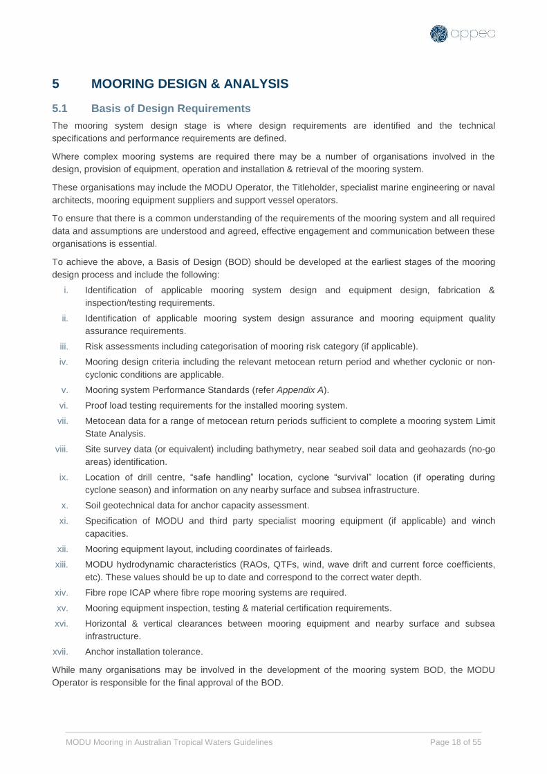
5.1 Basis of Design Requirements
The mooring system design stage is where design requirements are identified and the technical
specifications and performance requirements are defined.
Where complex mooring systems are required there may be a number of organisations involved in the
design, provision of equipment, operation and installation & retrieval of the mooring system.
These organisations may include the MODU Operator, the Titleholder, specialist marine engineering or naval
architects, mooring equipment suppliers and support vessel operators.
To ensure that there is a common understanding of the requirements of the mooring system and all required
data and assumptions are understood and agreed, effective engagement and communication between these
organisations is essential.
To achieve the above, a Basis of Design (BOD) should be developed at the earliest stages of the mooring
design process and include the following:
i. Identification of applicable mooring system design and equipment design, fabrication &
inspection/testing requirements.
ii. Identification of applicable mooring system design assurance and mooring equipment quality
assurance requirements.
iii. Risk assessments including categorisation of mooring risk category (if applicable).
iv. Mooring design criteria including the relevant metocean return period and whether cyclonic or non-
cyclonic conditions are applicable.
v. Mooring system Performance Standards (refer Appendix A).
vi. Proof load testing requirements for the installed mooring system.
vii. Metocean data for a range of metocean return periods sufficient to complete a mooring system Limit
State Analysis.
viii. Site survey data (or equivalent) including bathymetry, near seabed soil data and geohazards (no-go
areas) identification.
ix. Location of drill centre, “safe handling” location, cyclone “survival” location (if operating during
cyclone season) and information on any nearby surface and subsea infrastructure.
x. Soil geotechnical data for anchor capacity assessment.
xi. Specification of MODU and third party specialist mooring equipment (if applicable) and winch
capacities.
xii. Mooring equipment layout, including coordinates of fairleads.
xiii. MODU hydrodynamic characteristics (RAOs, QTFs, wind, wave drift and current force coefficients,
etc). These values should be up to date and correspond to the correct water depth.
xiv. Fibre rope ICAP where fibre rope mooring systems are required.
xv. Mooring equipment inspection, testing & material certification requirements.
xvi. Horizontal & vertical clearances between mooring equipment and nearby surface and subsea
infrastructure.
xvii. Anchor installation tolerance.
While many organisations may be involved in the development of the mooring system BOD, the MODU
Operator is responsible for the final approval of the BOD.

MODU Mooring in Australian Tropical Waters Guidelines Page 19 of 55
The BOD should be formally endorsed by key stakeholders in the mooring design. As a minimum this should
include the MODU Operator, the Titleholder and any specialist marine engineering or naval architects
involved in the design of the mooring system or the specification of mooring equipment.
Any material changes or deviations from the mooring system BOD should be reviewed, risk assessed and
approved by the original endorsers/approvers of the BOD under a documented MOC system.
See Appendix D for example of mooring BOD form.
5.2 Mooring Design Scope of Work
Under Australia’s offshore petroleum industry regulatory system the design and acceptance of the mooring
system is the responsibility of the MODU Operator.
The MODU Operator may sub-contract some or all of the mooring system design work to specialist marine
engineering or naval architects and/or incorporate elements of the mooring system design which have been
undertaken by the Titleholder.
The scope of the mooring system design should include the following:
i. Define mooring layout to accommodate subsea equipment, pipelines and surface facilities.
ii. Define load cases for maximum metocean conditions.
iii. Define type, size, grade, and quantity of mooring line components for a pre-laid system (if required).
iv. Define and optimize pretensions of the mooring lines; and determine cross-tensioning values.
v. Calculate maximum line tensions and anchor loads for all design conditions.
vi. Calculate the optimal line tensions for survival conditions and provide a plan that describes how to
slacken off tensions from operating to survival conditions in preparation for cyclones (this this needs
to be determined in conjunction with the MODU operator). Note that depending on the location-
specific mooring system design, an existing unbalanced load distribution between the mooring lines
could be made worse by inappropriate slackening of all mooring lines. This is particularly the case
for asymmetric mooring patterns.
vii. Determine the maximum offsets of the MODU and relevant clearances for intact and one-line-
damaged conditions.
viii. Check clearances between mooring lines and MODU and:
ix. Adjacent mooring lines and risers
x. Subsea equipment and pipelines
xi. Surface facilities
xii. Seabed (relevant for fibre rope inserts and swivels)
5.2.1 Standards and Codes
In Australian waters, API RP 2SK is typically referenced for the purposes of MODU mooring design.
5.2.2 Analysis Approach
Dynamic analysis (in frequency domain, or time domain) is a recommended practice.
5.2.3 Design criteria:
Strength criteria as per API RP 2SK should be met, as a minimum.
Offset criteria as per API RP 16Q, should be met, as a minimum.
Mooring line clearance (horizontal and vertical) criteria as per API RP 2SK, should be met as a
minimum.
If fibre ropes are used, API RP 2SM should be met.

MODU Mooring in Australian Tropical Waters Guidelines Page 20 of 55
5.2.4 Analysis Considerations
Mooring analysis should consider the following effects and sensitivities:
i. MODU response sensitivity to wave period. It is recommended to run sensitivity with varying wave
period and corresponding significant wave height for the governing load case.
ii. Effect of surge and tide, particularly for shallow water locations.
iii. Anchor installation tolerance, i.e. changes in anchor range and line heading.
iv. Location of mooring centre – this is often either the “safe handling” or “survival” location when
operating during cyclone season.
v. If fibre ropes are used, the non-linear stiffness of fibre rope should be modelled appropriately. Refer
to API RP 2SM for guidance.
vi. Allowance should be made for construction stretch (permanent elongation) of fibre rope caused by
maximum historical load. Refer to API RP 2SM for guidance. It should be particularly noted that axial
stiffness of as-new polyester ropes is much lower than in post-installed condition after the ropes are
pre-stretched, and system behaviour tends to be uncertain if construction stretch is not sufficiently
removed.
vii. If fibre ropes are used in conjunction with 6-strand wire ropes, consideration should be given to the
torque generated by 6-strand wire under tension and the effect of this torque on the fibre rope.
viii. When assessing vertical line clearance above infrastructure, consider leeward slack line catenary
under maximum conditions for both intact and SLF case.
ix. Mooring swivel type and rig swivel clearance above seabed should also be considered.
x. If there is a difference in load vs excursion between the mooring lines, consider optimising the line
pretension with respect to the governing criteria. Purpose of this is to optimise the load sharing
between mooring lines.
xi. Care should be taken to ensure that connecting hardware (with exception of ground chain
connecting links such as kenter-links or C-links) remains clear of the seabed under all load
conditions.
xii. Depending on mooring equipment inspection records (or lack of records) the MBS of mooring
equipment may need to be revised. (DNVGL-OS-E301 presents formulas for de-rating mooring
equipment).
xiii. Buoys shall be designed according to a recognised standard such as API RP 2SK or the OEM’s
standards.
xiv. Surface buoys shall be designed with a minimum of 25% buoyancy redundancy in all intact
conditions. If the buoy is compartmented, flooding of one compartment shall be considered a
damage case for analysis.

MODU Mooring in Australian Tropical Waters Guidelines Page 21 of 55
5.3 Metocean Return Period Criteria
MODU mooring should be assessed against an appropriate metocean return period. The appropriate return
period depends on level of risk associated with MODU mooring. Section 3 of this document provides
guidance on MODU mooring risk screening which categorises the mooring risk as either Low, Medium or
High.
Below table provides guidance on recommended minimum metocean return period based on Figure 2 in
Section 3.4.
Consequence Test
(Proximity)
No Yes
Likelihood Test
(Season)
Yes 10 20+ 10-20
No 5-10 10-20 10
Fail Pass
Risk Mitigation
Test
Figure 3: Minimum recommended metocean return period
Notes:
1. The above is guidance only, and higher or lower metocean return periods should be used if deemed
appropriate following a document risk assessment.
2. For mooring scenarios in close proximity to surface or subsea hydrocarbon infrastructure when
outside cyclone season, the likelihood of mooring failure may not be as large as when in cyclone
season, but the consequences may be the same or even more severe. For example, the MODU may
not be down-manned or evacuated when not in cyclone season. If a mooring failure results in
anchors dragging, pipeline damage or MODU drift there are inherent additional risks associated.
3. For cases where Risk Mitigation Tests have demonstrably failed, Return Period should be prescribed
based on consequence assessment.

MODU Mooring in Australian Tropical Waters Guidelines Page 22 of 55
5.4 Risk Based Mitigation Activities
Risk Based Mitigation Activities – Mooring Design & Analysis
Activity
No:
Activity Description L
ow
Med
ium
Hig
h
5.1 Quasi static mooring analysis. C NA NA
5.2 Frequency domain dynamic mooring analysis. R R HR
5.3 Time domain dynamic mooring analysis. NA C C
5.4 Independent metocean criteria. R NA NA
5.5 Site specific and joint maxima metocean criteria. C R HR
5.6 Analysis should consider the following sensitivities: Tp variation, allowance
for surge and tide.
C R HR
5.7 Site specific bathymetry. R HR HR
5.8 Anchor location tolerance checks (installation and drag limits). C R HR
5.9 For single line failure (damaged condition), anchor holding FOS should be
reported.
R HR HR
5.10 Site specific anchor analysis. C R HR
Note:
C Consider HR Highly Recommended
R Recommended NA Not Applicable

MODU Mooring in Australian Tropical Waters Guidelines Page 23 of 55
6 METOCEAN
This section provides a reference to generic metocean report for the North West Shelf (NWS) as well as a
general description of NWS metocean environment.
APPEA has commissioned RPS to prepare a guidance document [8] on metocean data which is
recommended to be used if site specific metocean data is not available for purpose of MODU mooring
analysis. The report presents metocean data tables (Tables 6.1 to 6.16 of the RPS document, Reference [8])
for four regions of the NWS and provides further detail on the oceanography and meteorology of the area.
The metocean data outlined in the report is generally conservative and may be used for MODU moorings of
all risk categories (Low, Medium, High). For medium and high risk MODU moorings, the operator may
acquire site specific data to reduce the metocean conditions, as a risk mitigation strategy.
6.1 Salient Oceanographic Features
Prevailing winds in the NWATW are distinctly seasonal, with synoptic winds predominantly from the SW
(SSW-W) during the summer (September to March), and from the E (E–SE) during winter (April to August).
Transitional seasons (autumn and spring), April and September are brief.
Wind waves (seas) reflect the directionality of the synoptic winds (i.e. SW–WSW in summer and ENE–E and
WSW in winter). Swell is perennial and approaches the study region primarily from the WSW.
Tides of the region are semi-diurnal (two highs and two lows per day) with a diurnal inequality (difference in
heights of successive highs and successive lows).
Semi-diurnal tidal currents are the most common feature of the local current regime, flowing predominantly
across the local bathymetry (roughly E–SE/W–NW) over the continental shelf.
Finally, the region is subject to severe tropical cyclones (in terms of both strength and frequency) in the
period between November and April. Tropical cyclones, and their associated wind, wave and current fields
represent the most severe environmental conditions across the NWATW.
6.2 Synoptic Meteorology
NWATW meteorological conditions can be separated into two seasons; the winter and summer seasons.
6.3 Winter Season
During winter, April to August, northern Australia, including the North West Australian waters, is dominated
by a flow of south-easterly air. For NWATW the winter season is characterised by east south-easterly winds.
6.4 Summer Season
The steadiness of the winter pattern is in marked contrast to the variability of the summer pattern. The
summer pattern generates primarily south-westerly winds and with lesser amounts from the west. Tropical
cyclones occur from the months of November to April, and cause severe wind, wave and current conditions.
6.5 The Transition Seasons
The periods April and September, are transition months during which either the summer or winter regime
may predominate, or conditions may vary between the two. The transition seasons diminish in significance
towards northern NWATW.

MODU Mooring in Australian Tropical Waters Guidelines Page 24 of 55
6.6 Extreme Wind Conditions
Extreme winds can occur throughout the year, easterly gales with wind speeds up to 22 m s-1 (44 knots) in
winter and tropical cyclones with speeds in excess of 50 m s-1 (100 knots) in summer. At the other end of the
spectrum, calms can also occur at any time during the year, but are more frequent in summer.
6.7 Easterly Gales (Trade Wind Surge)
Easterly gales (i.e. Trade Wind Surge) occur mostly between May and August as a result of the increase in
the atmospheric pressure gradient, which occurs when a strong high pressure cell moves from the Indian
Ocean into the western part of the Great Australian Bight. In spite of the name, the wind directions may be
between south-south-easterly and north-easterly. Wind speeds in the range 12.5 to 20 m s-1 (25 to 40 knots)
may occur twice per winter month.
6.8 Tropical Cyclones
The Australian tropical cyclone season runs from 1 November to 30 April with the majority occurring between
January and March. Tropical cyclones usually form in the Timor and Arafura Sea area, and then travel
initially in a general south-westerly direction. As the storm develops it can alter its course to travel in a south
or south-easterly direction. Further south, tropical cyclone paths become more variable, and storm intensity
generally increases reaching a maximum severity at about 20° latitude (i.e. the NWATW study region).
Fully mature tropical cyclones range in size from 100 km in diameter to well over 1500 km. Tropical cyclone
size (i.e. diameter) tends to be smaller when nearest to the equator (i.e. within 10°) and larger as the latitude
increases.
At maturity, these are the most severe storm type of the area and can produce sustained winds typically in
the range 25 to 35 m/s with severe sea conditions, typically 4.0 to 10.0 m significant wave height.
During an El Nino event identified by a negative Southern Oscillation Index and lower than average humidity,
the average occurrence of tropical cyclones in the tropical cyclone season is reduced. Conversely, during a
La Nina which has above average moisture in the atmosphere, storms are more frequent and more intense
than in average years.
6.9 Squalls
Squalls with heavy rainfall are associated with thunderstorms occurring at any time of the year. These events
can be widespread through the summer tropical cyclone season, especially with an active monsoon. The
squalls result from strong downdrafts in the cumulonimbus cloud (i.e. the outflow/air from the thunderstorm
downdraft spreads out as the air hits the ground or ocean surface). Winds associated with the squalls may
be in excess of 20 m/s for several hours, and in extreme cases may reach 25 to 30 m/s with instantaneous
gusts to 45 m/s.
6.10 Wave Climatology
The largest sea states in the NWATW area typically result from locally generated winds. West-southwest
swell of low amplitude is a perennial feature. Swell is generated by distant storms, and propagates to the
region of interest, slightly diminishing in height due to frictional attenuation while passing over the shallower
waters around Barrow Island and Rankin Bank. Swell is largely independent of the local winds. Sea refers to
the shorter period waves (i.e. typically < 9 seconds) generated by local winds in the immediate vicinity of a
particular site. The sea can be affected by the strength and duration of wind forcing, and by the available
distance (fetch) over which the generating wind blows.

MODU Mooring in Australian Tropical Waters Guidelines Page 25 of 55
The sea state of the NWATW comprises contributions from:
Southern Ocean swell: Southern Ocean Swell is a perennial feature of exposed NWATW. Typically,
this swell arrives at the outer edge of the continental shelf from the south and southwest, before
refracting during propagation across the shelf, to become more westerly and even north-westerly
near-shore.
“West Coast” swell: During summer, strong southerly diurnal coastal winds are a feature of the
Western Australian coastline between Perth and the North West Cape. These winds generate sea,
and the resulting dispersive swell refracts around the North West Cape and Barrow Island onto the
North West Shelf, producing a “burst” of swell passing the area off Dampier, near the edge of the
continental shelf, several hours after midnight.
Tropical cyclone sea and swell: Tropical cyclones will generate waves (sea and swell). Depending
upon such parameters as storm size, intensity, relative location and forward speed, tropical cyclones
may generate sea and swell with periods ranging from 5 to 18 seconds from any direction, with
significant wave heights ranging from 1 to 15 m. Typically, most tropical cyclones will generate
significant wave heights of 4 to 10 m across the NWATW region. Very intense storms will generate 11
to 16 m significant wave height.
Local wind-generated sea: Local wind-generated sea typically ranges in period from 2 to 7 seconds,
but may attain 8 seconds under very persistent forcing. Heights are extremely variable, ranging from
0 to 4 m under non-tropical cyclone forcing. The direction of local sea would be the same as that of
the generating wind, unless local bathymetric effects (refraction, diffraction, shielding, etc) act to
influence wave direction. In NWATW study area, the seas will be predominantly from the SW–WSW
in summer and from the ENE–E and WSW in winter. The most noticeable wind seas causing very
rough seastates, on the NWATW are those caused by the winter easterly winds, off the Onslow to
Port Hedland coast.
6.11 Current Regime
Principal current driving mechanisms for NWATW are:
1. Normal (barotropic) tidal currents: The most observable currents of the area are tidal currents
produced by the large rise and fall of the tide (known as barotropic tidal currents). These have peak
values of about 0.4 m s-1 within Mermaid Sound; and increase in magnitude in an offshore direction to
the shelf edge, before decreasing in deeper waters.
2. Internal waves (baroclinic tide) and high frequency currents;
3. Local wind induced currents: Local wind forcing exerts a shear on the sea surface, which generates
waves and transfers horizontal momentum to the water column. The processes of turbulence and
mixing subsequently allow for vertical transfer of this horizontal momentum through the water column.
Under ambient conditions these currents are typically 0.05 to 0.15 m/s.
6.12 Temperature and Salinity Distributions
Over most of the NWATW, density structure is controlled by the variability of water temperature, because
salinity remains relatively uniform.
Surface temperatures and vertical gradients attain their maximum (about 30°C) in late summer. On the outer
shelf, the temperatures range down to about 23°C at depths of about 100m. The temperature stratification
over the NWATW collapses or becomes isothermal (due to surface cooling and consequent overturning) for
one or two months in early winter (water depths to 100m).
6.13 Tidal range
Tides across the NWATW region are semidiurnal (two highs and two lows each day), with a small diurnal
inequality, and a well-developed spring (large) to neap (small) tidal range.

MODU Mooring in Australian Tropical Waters Guidelines Page 26 of 55
6.14 Risk Based Mitigation Activities
Risk Based Mitigation Activities – Metocean
Activity
No:
Activity L
ow
Med
ium
Hig
h
6.1 Use generic metocean data (See RPS report [8]). R C C
6.2 Use site specific metocean data. NA R HR
6.3 Use Site specific Tp/Hs contours for wave period sensitivity. NA R HR
Note:
C Consider HR Highly Recommended
R Recommended NA Not Applicable

MODU Mooring in Australian Tropical Waters Guidelines Page 27 of 55
7 GEOTECHNICAL
7.1 Geology of the NWATW of Australia and Geohazards
Below is a brief overview of the geotechnical, geological and geohazard considerations for anchors in
NWATW of Australia:
i. Shallow geology is dominated by calcareous soils which differ from soils in other regions by:
Being more susceptible to cyclic degradation (cyclic anchor UHC should be taken into
account).
Often having chain frictions lower than 1.0 (which is referenced in API RP 2SK). Reference [9]
provides guidance on the calculation of chain friction factor in calcareous soils.
ii. Cemented calcarenite/limestone units can be found in shallower water:
Shallow water depths up to about 120m are likely to have shallow cemented layers and this
can be examined through geophysical survey, geotechnical investigation and/or ROV
inspection/probing. Ispoach maps of depth to cemented calcarenite (or thickness or superficial
deposits) may prove useful for risk identification and assessment.
If at shallow depth, cemented layers will impede anchor embedment and limit anchor
capacity.
If at surface, there will be no anchor embedment.
Stevshark™ type anchors are better suited to rock conditions.
Heavier or ballasted anchors provide a better chance of penetrating through weakly or variably
cemented layers, however these anchors will also require higher tensions to achieve
embedment.
A site specific anchor capacity assessment is recommended for all areas with potential
cemented calcarenite, particularly for MODU moorings in medium and high risk categories.
If drag anchors are unable to achieve the required capacities, pile foundations may be used as
an alternative. The design and installation of pile anchors generally requires a longer lead
time, e.g. 12 to 18 months.
iii. Other geohazards include the following. All geohazards can be summarised in geohazard no-go
zone maps:
Unstable slopes / scarps should be avoided.
The toe of scarps and turbidite channels may contain unpredictable mixed deposits resulting
from historical failures and should be avoided.
Changes in seabed gradients causing anchor uplift loads should be avoided.
Pock marks / shallow gas should be avoided as anchor capacity will be reduced.
7.2 Estimating anchor capacity in calcareous soils
Anchor manufacturers’ (such as Vryhof) anchor capacity look-up charts are not applicable to calcareous soils
and should not be relied upon as they overestimate anchor capacities.
Anchor capacities should be determined through site specific anchor analysis using methods appropriate to
calcareous soils and taking into account cyclic loading (detrimental) and consolidation (beneficial). The
required inputs for anchor analysis are:
Geological model and presence of any cemented layers, e.g. from geophysical data.
Soil strength data, e.g. cone penetration test (CPT), or borehole data.
Anticipated time between anchor installation and loading and the consolidation characteristics of the soil
should be considered.

MODU Mooring in Australian Tropical Waters Guidelines Page 28 of 55
Post-installation anchor drag lengths should be considered and accounted for, i.e. the anchor drag
corresponding to maximum anchor holding capacity should be checked in the mooring analysis by reducing
the anchor range.
Anchor drag depth should be checked against anticipated geology and the risk of shallow cemented units
that will impede anchor embedment and hence limit anchor UHC.
7.3 Anchor installation and testing requirements
Mooring lines should be proof-load tested after installation. Proof-loading can be achieved using AHV during
prelay (if applicable) and/or by cross-tensioning using MODU winches. The purpose of proof-loading the
mooring lines and anchors is to:
achieve adequate anchor embedment, in case of drag/plate anchors;
eliminate slack in the ground chain and develop inverse catenary;
prove installation holding capacity, noting that anchor capacity may be lower in a storm due to cyclic
degradation of the soil;
reduce anchor drag distances during storm loading;
proof-load other components of the mooring system (during cross-tensioning with rig winches).
As per API RP 2SK, for mobile moorings with drag anchors, the test load should be determined by type of
anchors, soil condition, winch pull limit and anchor retrieval.
Section 7.4.3 of API RP 2SK gives following minimum requirements for mobile MODU mooring proof-load:
Test load at anchor shank should not be less than 3 times the anchor weight.
The mooring test load at winch should not be less than the mean line tension for an intact mooring
under the maximum design condition. (Note, API RP 2SK states that this requirement is for “close
proximity moorings”. See Section A1 for definition).
Duration of test load should be at least 15 minutes for each line with no detectable anchor drag.
Anchors may be fitted with transponders to provide additional information on anchor embedment and
orientation.
ROVs may be used as a visual check on anchor embedment during and/or post-installation.
7.3.1 Contingencies
In the event that mooring test load is not achieved, the following contingencies may be considered:
Increase consolidation time (soaking anchors) to increase holding capacity.
Increasing anchor range or adding more ground chain to reduce load at anchor.
Using ballasted anchors to achieve greater embedment.
Using larger anchors.
7.4 Sharing geotechnical information
There is potential for Operators to share:
Anchor installation and/or test data, e.g. by adding information to a shared or central database.
Geotechnical information in shared anchoring locations where applicable.
R&D results through JIPs, university research, conferences and other forums, e.g. Society for
Underwater Technology (SUT), Offshore Site Investigation and Geotechnics (OSIG). To be updated if
specific JIPs are formed.

MODU Mooring in Australian Tropical Waters Guidelines Page 29 of 55
7.5 Risk Based Mitigation Activities
Risk Based Mitigation Activities – Geotechnical
Activity
No:
Activity Description: L
ow
Med
ium
Hig
h
7.1 Cross-tensioning load at winch equivalent to mean line tension for an
intact mooring under the maximum design condition.
C C R
7.2 Site specific anchor analysis and good understanding of geological model
(presence and depth of cemented layers).
C R HR
7.3 Anticipated anchor drag checked as anchor range sensitivity in mooring
analysis.
C R R
7.4 Monitor anchor embedment using transponders fitted to anchors, or ROV if
transponders are not available.
C R R
7.5 Sensitivity study in mooring analysis for reduced anchor UHC. C R R
Note:
C Consider HR Highly Recommended
R Recommended NA Not Applicable

MODU Mooring in Australian Tropical Waters Guidelines Page 30 of 55
8 MOORING EQUIPMENT
8.1 Scope
This section is intended to provide guidance on the design, specification, testing, maintenance and storage
of all MODU mooring system equipment normally installed or used on or immediately above the seabed
including anchors, mooring chain & accessories, steel wire mooring rope (including vessel work-wires, tow
wires and PCPs), fibre mooring rope and buoys. This includes both MODU Operator owned and rented
equipment.
8.2 Manufacturing, Testing & Certification
Equipment to be manufactured to internationally recognised standards.
Mooring Chain & Accessories: DNVGL-OS-E302 or equivalent
Wire Rope: DNVGL-OS-E304 or equivalent
Fibre Rope: DNVGL-OS-E303 or API RP 2SM or equivalent and manufacturer’s recommendations
Fibre Rope Damage Assessment: DNVGL-RP-E304 or equivalent
MODU Anchor Winches ISO 9089 & ABS–DNVGL Class Requirements
Mooring system components must have full traceability & inspection documentation records in accordance
with API RP 2I Annex A.
Mooring equipment must be certified by a Recognised Classification Society (RCS) who is a member of the
International Association of Classification Societies (IACS) with rules and standards applicable to MODU
design, construction and operation.
Equipment manufacturing, testing & certification records should be available for individual components.
Where mooring equipment traceability records are incomplete, the equipment item should be either replaced
or re-certified according to the re-certification requirements included in the above standards at the earliest
opportunity.
8.3 Equipment Storage
Equipment storage conditions can have a significant impact on the performance and service life of mooring
equipment. Storage time may need to be included as ‘in service’ time for the purposes of equipment
maintenance & inspection.
Storage time should be regarded as ‘in-service’ time unless detailed records of equipment maintenance &
inspection and storage conditions are available to demonstrate that the equipment has been properly
maintained & stored in compliance with the OEM’s recommendations.
Steel wire rope in tropical conditions is susceptible to corrosion and should be stored under cover or suitable
protection from the elements.
Fibre rope is susceptible to degradation from UV radiation and should be stored under cover or suitable
protection from the elements unless specifically designed for high UV radiation exposure.
8.4 Maintenance & Service History
Maintenance, inspection & repair records for all mooring equipment components should be included in a
Planned Maintenance System (PMS) or similar system.
Where mooring equipment is owned by a mooring equipment supplier an alternative PMS should be used for
all mooring equipment items.

MODU Mooring in Australian Tropical Waters Guidelines Page 31 of 55
The PMS should include details of storage conditions & durations for all equipment items to ensure that
equipment inspections based on ‘service years’ are scheduled appropriately.
Equipment maintenance & service history records must be available for individual components.
The PMS system should be capable of maintaining the traceability, service history & storage conditions of
mooring equipment items such as connector links, PCPs which are frequently removed and/or replaced.
8.5 Use of Fibre Mooring Lines
Fibre tethers reliant on an external jacket to restrain the individual load bearing fibres are not suitable for use
in MODU mooring systems.
The fibre rope jacket must be permeable to ensure that the rope is free flooded when submerged.
Fibre ropes must be designed to resist seabed soil ingress and shall be specified with an appropriate filter to
exclude soil ingress.
For service conditions where the fibre rope will be exposed to sunlight (i.e. shallow water service and/or
outdoor storage), the fibre ropes must be designed to resist high levels of UV radiation and must be
manufactured from materials highly resistant degradation from UV radiation.
Fibre ropes should be designed to resist marine growth ingress and be specified with an appropriate filter to
prevent marine growth between load bearing fibres.
Where fibre ropes are used as part of MODU mooring system:
The fibre rope must remain submerged at all times during service.
The fibre rope should remain clear of the seabed during service including during installation and
handling, unless the fibre rope has been designed and qualified to prevent the ingress of seabed
soils.
Fibre ropes should be protected from UV radiation when not in service.
Fibre rope damage assessments must only be completed by competent personnel in compliance with
DNVGL-RP-E304.
Repairs to load bearing fibre sub-rope or filter must only be attempted by the rope manufacturer and must be
re-certified as per DNVGL-OS-E303 requirements.
Field repairs to the non-load bearing outer jacket may be undertaken by competent personnel.

MODU Mooring in Australian Tropical Waters Guidelines Page 32 of 55
8.6 Risk Based Mitigation Activities
Risk Based Mitigation Activities – Mooring Equipment
Activity
No:
Activity Description: L
ow
Med
ium
Hig
h
8.1 Desktop certification check. R HR HR
8.2 Desktop service history, maintenance, inspection, repair & storage
records check.
R HR HR
8.3 Independent QAQC verification of equipment condition and OEM
certification in compliance with Class requirements.
C C R
8.4 Independent review of mooring equipment, component specifications,
in-service history and PMS records.
C R HR
8.5 Detailed review of mooring equipment handling & installation
procedures.
C R HR
8.6 Where mooring equipment is not compliant with the manufacturing or
testing standards described in Section 8.2, gap analysis to be completed
and consider replacing items with compliant equipment.
R R HR
8.7 Use of good condition pre-lay equipment and/or replacement of MODU
equipment with full certification package.
C C R
8.8 Use of new pre-lay equipment and/or replacement of MODU equipment
with full certification package.
C C R
8.9 Destructive testing results to confirm MBS of MODU owned wire or fibre
rope used in mooring analysis.
C C R
8.10 Re-schedule Visual & MPI/NDT PMS equipment inspection and/or
maintenance requirements for completion before installing mooring
system.
C R HR
8.11 Re-complete Visual & MPI/NDT PMS equipment inspection and/or
maintenance requirements for mooring equipment before installing
mooring system (except where new equipment is being used).
C C R
8.12 Full certification and testing of MODU’s mooring system including anchor
winches and certification of fairlead sheave and shaft bearings.
C C R
Note:
C Consider HR Highly Recommended
R Recommended NA Not Applicable

MODU Mooring in Australian Tropical Waters Guidelines Page 33 of 55
9 MOORING INSPECTION
9.1 Scope
This section is intended to provide guidance on the inspection, maintenance and repair of all MODU mooring
system equipment normally installed or used on or immediately above the seabed including: anchors,
mooring chain & accessories, steel wire mooring rope (including vessel work-wires and PCC’s), fibre
mooring rope and buoys.
9.2 Equipment Inspection Standards & Procedures
Mooring equipment shall be inspected to internationally recognised standards and procedures.
Mooring Chain & Accessories: DNVGL-OS-E302 or API RP 2I
Wire Rope: DNVGL-OS-E304 or API RP 2I
Fibre Rope: DNVGL-OS-E303 & E305 or API RP 2I/2SM
Fibre Rope Damage Assessment: DNVGL-RP-E304 or equivalent
Mooring equipment inspections should be conducted using standard inspection checklists. Standardised
checklists are included in the GOMO.
Inspection reports should include photographic evidence of all components visually inspected and MPI
tested.
Mooring equipment inspection reports & checklists should be recorded in the PMS and made available to all
parties involved in the design, maintenance and operation of the mooring system, (i.e. the MODU Operator,
the Titleholder and any Mooring Equipment & Services provider).
9.3 Inspector Competence & Training
Personnel involved in the inspection, repair and maintenance of mooring equipment must be competent and
hold appropriate certification where applicable. This requirement applies to all mooring operations regardless
of risk level.
Organisations providing personnel engaged in the inspection, repair and maintenance of mooring equipment
must have a competence management system which specifically addresses the formal and on-the-job or
task based training requirements, assessment requirements and certification or qualification requirements for
personnel on each specific type of mooring equipment and inspection type.
The organisation’s competency system should be externally audited on a regular basis by an independent
auditor.
9.4 Chain, Accessories & Wire Rope Visual Inspection
Visual inspection intervals for mooring equipment should comply with the minimum requirements as per API
RP 2I (see Table 6).
MODU Mooring in Australian Tropical Waters Guidelines Page 34 of 55
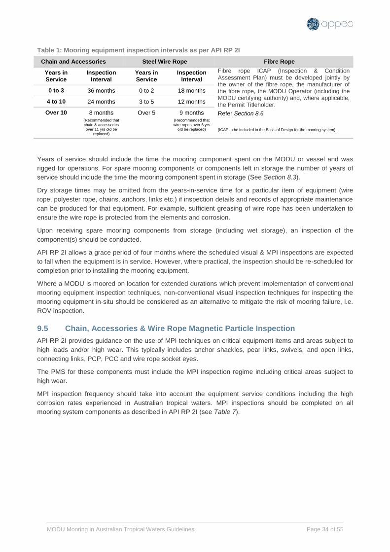
Table 1: Mooring equipment inspection intervals as per API RP 2I
Chain and Accessories Steel Wire Rope Fibre Rope
Years in Service
Inspection Interval
Years in Service
Inspection Interval
Fibre rope ICAP (Inspection & Condition Assessment Plan) must be developed jointly by the owner of the fibre rope, the manufacturer of the fibre rope, the MODU Operator (including the MODU certifying authority) and, where applicable, the Permit Titleholder.
Refer Section 8.6
(ICAP to be included in the Basis of Design for the mooring system).
0 to 3 36 months 0 to 2 18 months
4 to 10 24 months 3 to 5 12 months
Over 10 8 months (Recommended that chain & accessories over 11 yrs old be
replaced)
Over 5 9 months (Recommended that wire ropes over 6 yrs
old be replaced)
Years of service should include the time the mooring component spent on the MODU or vessel and was
rigged for operations. For spare mooring components or components left in storage the number of years of
service should include the time the mooring component spent in storage (See Section 8.3).
Dry storage times may be omitted from the years-in-service time for a particular item of equipment (wire
rope, polyester rope, chains, anchors, links etc.) if inspection details and records of appropriate maintenance
can be produced for that equipment. For example, sufficient greasing of wire rope has been undertaken to
ensure the wire rope is protected from the elements and corrosion.
Upon receiving spare mooring components from storage (including wet storage), an inspection of the
component(s) should be conducted.
API RP 2I allows a grace period of four months where the scheduled visual & MPI inspections are expected
to fall when the equipment is in service. However, where practical, the inspection should be re-scheduled for
completion prior to installing the mooring equipment.
Where a MODU is moored on location for extended durations which prevent implementation of conventional
mooring equipment inspection techniques, non-conventional visual inspection techniques for inspecting the
mooring equipment in-situ should be considered as an alternative to mitigate the risk of mooring failure, i.e.
ROV inspection.
9.5 Chain, Accessories & Wire Rope Magnetic Particle Inspection
API RP 2I provides guidance on the use of MPI techniques on critical equipment items and areas subject to
high loads and/or high wear. This typically includes anchor shackles, pear links, swivels, and open links,
connecting links, PCP, PCC and wire rope socket eyes.
The PMS for these components must include the MPI inspection regime including critical areas subject to
high wear.
MPI inspection frequency should take into account the equipment service conditions including the high
corrosion rates experienced in Australian tropical waters. MPI inspections should be completed on all
mooring system components as described in API RP 2I (see Table 7).

MODU Mooring in Australian Tropical Waters Guidelines Page 35 of 55
Table 2: recommended API internal as per API RP 2I
Years in Service MPI Interval
0 to 3 36 months
4 to 10 24 months
Over 10
8 months (Recommended that chain & accessories over 11 yrs old be replaced)
Completing MPI activities in the field is difficult, time-consuming and expensive. Consideration should be
given to replacing components requiring MPI at a pre-determined service life. Replaced components may be
sent ashore to undergo the necessary inspections.
9.6 Fibre Rope Inspection
A fibre rope ICAP (Inspection & Condition Assessment Plan) must be developed jointly by the owner of the
fibre rope, the manufacturer of the fibre rope, the MODU Operator (including the MODU certifying authority)
and, where applicable, the Permit Titleholder.
The ICAP should be included in the Mooring System Basis of Design as described in Section 4.1.
Fibre ropes must be inspected and damage assessed by trained, experienced and competent personnel in
accordance with DNVGL-RP-E304.
The Fibre Rope ICAPs should, as a minimum, address the following principles:
Rope design and application
Storage and condition management
Installation design considerations
Spooling, deployment and recovery management
Records of in-service history/component usage history
Inspection and planned maintenance system (PMS) requirements
Damage assessment
Rope discard, repair and replacement criteria
9.7 Wire Rope Sockets
Consideration should be given to slipping & cutting steel wire mooring lines and re-socketing the wire at
regular intervals. The re-socketing interval should be based on historical experience, the condition of the wire
socket observed during regular visual inspections and previous service history. In tropical regions, wire ropes
are typically re-socketed at service life intervals of 2–3 years.
Wire rope re-socketing must be completed in accordance with DNVGL-OS-E304 and shall only be completed
by trained, experienced and competent personnel.
Where wire ropes are being slipped & cut and re-socketed, a section of wire removed from the mooring line
should undergo destructive testing to establish the residual MBS and confirm it is within allowable limits as
per API RP 2SK.
9.8 Fibre Rope Eye Splice
Fibre rope eye re-splicing must not be attempted in the field. Fibre rope eye re-splicing shall only be
completed by the rope manufacturer and must be re-certified as per DNVGL-OS-E303 requirements.

MODU Mooring in Australian Tropical Waters Guidelines Page 36 of 55
9.9 Pre & Post Tropical Cyclone Inspection Requirements
Cyclone season preparation and mooring inspection activities should, as a minimum, comply with the
guidance provided in API RP 2I Annex B.
Where a MODU’s mooring system has been subjected to cyclonic metocean conditions resulting in a failure
of a mooring system component, any subsequent mooring equipment inspection, repair, load testing and
return to service should, as a minimum, comply with the guidance provided in API RP 2I Annex B.
Where a MODU is moored on location for extended durations which prevent implementation of conventional
mooring equipment inspection techniques and the mooring system has been subjected to cyclonic metocean
conditions, non-conventional visual inspection techniques for inspecting the mooring equipment in-situ may
be considered post-cyclone event, i.e. risk based ROV inspection techniques.

MODU Mooring in Australian Tropical Waters Guidelines Page 37 of 55
9.10 Risk Based Mitigation Activities
Risk Based Mitigation Activities – Mooring Inspection
Activity
No:
Activity Description: L
ow
Med
ium
Hig
h
9.1 Desktop certification check. R HR HR
9.2 Check mooring equipment current within MODU or equipment supplier
PMS.
R HR HR
9.3 Independent audit of equipment supplier and MODU PMS to confirm
inspection & maintenance requirements are completed as required.
C R HR
9.4 Independent QAQC verification of equipment by qualified marine
engineering/naval architect.
C C R
9.5 Review and, where required, re-complete Visual Inspection PMs prior to
commencing operations with specialist mooring contractor.
C R HR
9.6 Review and, where required, re-complete MPI/NDT inspection PMs prior to
commencing operations with specialist mooring contractor.
C R HR
9.7 Re-socket MODU owned steel wire rope sockets prior to commencing
operations with specialist mooring contractor.
C C R
9.8 Destructive testing of MODU owned steel wire rope to confirm MBS. C C R
9.9 Visual inspection of mooring lines post-cyclone (where mooring system
remained intact).
NA C C
9.10 MPI of mooring lines post-cyclone (where mooring system remained
intact).
NA C C
9.11 ROV in-situ visual inspection of mooring lines post-cyclone (where mooring
system remained intact).
NA C C
9.12 ROV in-situ visual mooring line inspection programme where MODU is
moored for extended durations (i.e. multiple well development drilling on a
single drill centre) and conventional visual/MPI inspections are not
practical.
C C R
9.13 ROV in-situ visual inspection of mooring lines post-installation. NA C C
9.14 Audit of specialist mooring contractor’s competence system and training
records.
C C R
9.15 Full certification and testing of MODU’s mooring system including anchor
winches & fairleads.
C C
Note:
C Consider HR Highly Recommended
R Recommended NA Not Applicable
MODU Mooring in Australian Tropical Waters Guidelines Page 38 of 55
10 MOORING OPERATIONS
10.1 Scope
This section is intended to provide guidance on the installation & recovery for all MODU mooring systems
including pre-laid equipment using wire or fibre rope mooring lines. Planning of MODU mooring operations
should consider:
Compliance with Local, Governmental and Class Guidelines, Recommended Practices and legal
requirements. (e.g NOPSEMA / APPEA / DNV / GOMO)
Operational standards & procedures
MODU, Mooring Contractor and Vessel crew competency and training
Mooring design, rigging and handling
Mooring installation & recovery procedures
Marine operations
Tropical Cyclone preparation & response
10.2 Operations Standards & Procedures
Mooring operations shall be conducted according to internationally recognised standards & procedures. The
following are endorsed:
Vessels: Guidelines for Offshore Marine Operations (GOMO)
Competence: DNVGL-ST-0027:2014-04
10.3 Vessel and MODU Personnel Competence & Training
Personnel involved in the installation of mooring equipment shall be competent in accordance with
DNVGL-ST-0027:2014-04.
Organisations providing personnel engaged in the installation of mooring equipment shall have a
competence management system which specifically addresses the formal and on-the-job or task-based
training requirements, assessment requirements and certification or qualification requirements for personnel
on each specific type of mooring equipment.
Vessel & MODU Operator’s competence management systems should be capable of recording their field
personnel’s experience with mooring installation & retrieval operations.
The organisations competency system should be externally audited on a regular basis by an independent
auditor.
10.4 Mooring System Rigging and Handling
To avoid unnecessary damage and ensure asset integrity, consideration must be given to MODU mooring
operations and a detailed design review should consider as a minimum:
Component placement within conventional / pre lay mooring line configurations.
Lashing / rigging methodology used to secure devices external to any in-line components (clamps,
flotation devices, riser arrangements etc).
Safe handling / recommended practices to avoid fatigue and maintain equipment integrity.

MODU Mooring in Australian Tropical Waters Guidelines Page 39 of 55
10.5 Mooring Installation & Recovery Procedures
Planning for the mooring operation shall be carried out in advance to allow for sufficient time for design and
analysis of the mooring system as described in this document. This includes the appropriate amount of time
to complete the required inspections and maintenance that must be completed prior to the mooring
operation.
The MODU Operator shall prepare installation procedures for the mooring system as described in GOMO.
Where components of the mooring system are not owned by the MODU Operator, the preparation of
procedures may be outsourced to a specialist marine contractor. However, regardless of the ownership of
individual equipment items or preparation of installation & retrieval procedures, the approval of these
procedures lies exclusively with the MODU Operator.
Pre rig move checklists as described in the GOMO should be provided to assist MODU & Vessel crews in
preparing the MODU moves and mooring installation & retrieval operations.
The mooring installation & recovery procedures shall be reviewed and approved by all parties involved in the
design, installation & retrieval of the mooring system including MODU Operator, Titleholder, Vessel Operator
and any specialist contractors providing mooring equipment or services.
The mooring installation & recovery procedures should address how the minimum clearance requirements
are to be maintained.
If mooring lines need to be pre-laid on the seabed, they must not be laid on subsea equipment.
Anchor handling and transfer operations shall not take place above subsea equipment and pipelines. If an
anchor handling vessel is required to transit over subsea infrastructure while installing a mooring line the
anchor must be decked & secured prior to transiting over the infrastructure.
The mooring installation & recovery procedures shall include reference to appropriate ‘safe handling’
locations with sufficient horizontal clearance from subsea infrastructure for heavy lift operations such as
subsea BOP and anchor handling.
The mooring installation & recovery procedures should include reference to an appropriate ‘survival’ location
where the MODU will be positioned during extreme weather events. The mooring system should be
designed such that mooring line load distributions are symmetrical at this location to minimise the risk of an
individual mooring line failure during a severe weather event.
Where practical, the survival location should be located clear of any subsea infrastructure to minimise the
risk of dropped objects from the MODU impacting on subsea infrastructure during severe weather events.
The mooring installation & recovery procedures shall include minimum required line tensions to ensure
mooring system components such as wire rope, fibre rope and chain/rope connectors remain clear of the
seabed including during kedging to safe handling & survival locations. The minimum line tensions must
account for the slacking off of line tensions at the survival location during severe weather events to ensure
that chain/rope connectors remain clear of the seabed in the slacked off condition. Leeward slack lines
during severe weather events should also be considered.
On occasion, there may be a requirement for mooring system components such as wire rope, fibre rope and
chain/rope connectors etc to contact the seabed. Any requirement for mooring system components to
contact the seabed other than those components specifically designed for this purpose, i.e. mooring chain
etc, should be considered in the mooring system BOD.
Where a suitable vessel equipped with an ROV is available, consideration should be given to ROV visual
inspections of the touchdown points, fibre rope and any jewellery and subsurface buoys in the mooring line.
For close-proximity mooring in cyclone season, it is recommended that a competent and established third
party marine surveyor or mooring engineer be on-board the MODU to oversee the installation/disconnection

MODU Mooring in Australian Tropical Waters Guidelines Page 40 of 55
of the mooring system and verify that the mooring system is installed according to the mooring design and
analysis.
Where mooring equipment is being installed or retrieved in close proximity to subsea infrastructure,
consideration should be given to the use of real time 3D visualisation survey systems to assist in the position
monitoring and placement of mooring equipment.
10.6 Marine Operations
A Management of Change process shall be implemented for any material changes required to the approved
mooring installation & recovery procedures. Any changes to procedures should be approved by the same
parties that approved the original procedures.
Mooring installation procedures shall include anchor positioning tolerances. In the event that anchors are not
positioned within the required tolerance, mooring design calculations should be re-done using as-built anchor
positions to confirm that the mooring design still meets design requirements, unless anchor positioning
tolerance has been considered in mooring analysis.
Mooring installation and recovery procedures shall ensure that wire or fibre rope components do not come
into contact with the seabed to prevent damage to these components unless this requirement has been
considered in the mooring system BOD.
Where mooring equipment is planned to be decked on the vessel for any reason, consideration should be
given to having competent specialist mooring contractor personnel on board the vessel to assist vessel
crews with the handling of mooring equipment.
All mooring lines should have detailed mooring line configuration drawings prepared prior to installation or
retrieval describing each component. Images of each component should be included to aid vessel crew in
the identification of all components where mooring line jewellery is assembled on a vessel.
Mooring line configuration drawings shall be approved by the MODU Operator, Titleholder and Specialist
Mooring Contractor prior to installation. Any changes to the approved mooring line configuration should be
approved via the Management of Change process.
10.7 Tropical Cyclone Preparation & Response
MODU specific tropical cyclone response procedures must be developed and reviewed prior to each cyclone
season. Checklists should be provided to assist MODU crews in preparing the MODU for de-manning. An
example Cyclone Preparation Checklist is provided in Appendix B.
MODU Operators shall ensure that procedures for slacking off mooring lines to storm tension are done in
accordance with the location specific mooring analysis. Storm tensions must ensure that chain/wire
crossovers retain adequate clearance from the seabed under cyclonic conditions to reduce the risk of
equipment failure.
MODU should be kedged to the mooring centre, or alternative location where the performance of the
mooring system is optimal and overall mooring risk is minimised.
Where MODUs are operating in areas close to manned facilities, consideration should be given to holding
joint facility exercises for a scenario where a MODU is adrift. This may need to include other Titleholders
where their facilities are in the vicinity of the MODU.
Contingency plans should be developed in the event of a MODU mooring system failure, including during
cyclones where the MODU has been de-manned. An example of a MODU Mooring Failure flow chart is
provided in Appendix C.
Where MODU is operating in areas close to manned facilities, consideration should be given to installing a
pre-rigged emergency tow bridle on the MODU to allow an emergency tow line to be established without
having to board the MODU and potentially expose personnel the HSE risks associated with a collision.

MODU Mooring in Australian Tropical Waters Guidelines Page 41 of 55
Consideration should be given to installing a Position Indicating Transponder with an independent power
supply to ensure that any MODU loss of station-keeping or mooring failure event to be identified as soon as
possible.
Consideration should be given to installing winch tension data recorders with an independent power supply
to allow the recording of actual mooring loads experienced by the MODU to provide data on actual loads
experienced during the cyclone event and identify whether mooring equipment has been over-loaded while
the MODU is de-manned.

MODU Mooring in Australian Tropical Waters Guidelines Page 42 of 55
10.8 Risk Based Mitigation Activities
Risk Based Mitigation Activities – Mooring Operations
Activity
No:
Activity Description: L
ow
Med
ium
Hig
h
10.1 Consider installation of a Position Indicating Transponder with independent power supply.
C R HR
10.2 Identify ‘safe handling’ location for heavy lifts including BOPs. R HR HR
10.3 Identify ‘survival’ location for cyclone de-manning over subsea infrastructure with symmetric loading of mooring lines.
NA R R
10.4 Confirm minimum mooring line tensions required during cyclone activity, ensure these are understood by MODU marine personnel and are included in the Cyclone Response Checklist.
NA HR HR
10.5 Develop MODU specific Cyclone Response Checklists for preparing for cyclone activity and de-manning the MODU.
NA HR HR
10.6 Develop Cyclone Response Checklists for facilities in Close Proximity to the MODU and potentially de-manning and/or suspending production.
NA R HR
10.7 Develop contingency plans for MODU mooring system failure including during cyclone events with the MODU de-manned.
C R HR
10.8 Develop contingency plans for facilities in Close Proximity to the MODU in the event of a MODU mooring system failure including during cyclone events with the MODU de-manned.
NA R HR
10.9 Deploy mooring equipment specialists onto anchor handling vessels during mooring installation & retrieval to minimise the risk of equipment damage to incorrect handling practices.
C R HR
10.10 Audit of specialist marine equipment contractor’s competence system and training records.
C C R
10.11 Deploy marine surveyor or mooring engineer in field to oversee the installation/disconnection of the mooring system and verify that the mooring system is installed according to the mooring design and analysis.
C R HR
10.12 Use real time 3D visualisation survey systems to assist in the position monitoring and placement of mooring equipment.
C R R
10.13 Install Emergency Tow Bridle on MODU to allow tow line to be established without boarding drifting unmanned MODU.
NA C C
10.14 Hold Emergency Response exercise with a drifting unmanned MODU scenario including Titleholders operating production facilities in close proximity to the MODU location.
NA C C
10.15 Re-schedule MODU operations outside of cyclone season. NA C C
10.16 Conduct ROV inspection after hook-up and cross-tensioning to verify and validate the integrity of the mooring system.
C C R
Note:
C Consider HR Highly Recommended
R Recommended NA Not Applicable

MODU Mooring in Australian Tropical Waters Guidelines Page 43 of 55
REFERENCES 1. American Petroleum Institute’s (API) Recommended Practice (RP) 2SK – 3rd Edition
2. American Petroleum Institute’s (API) Recommended Practice (RP) 2SM – 2nd Edition
3. American Petroleum Institute’s (API) Recommended Practice (RP) 2I – 3rd Edition
4. NOPSEMA Information paper. MODU Mooring systems in cyclonic conditions
5. NOPSEMA Guidance note: ALARP N-04300-GN0166 Rev 6 June 2015
6. NOPSEMA Guidance note: The Safety Case in Context: An overview of the Safety Case regime N-
04300-GN0060 Rev 6 June 2013
7. Offshore Petroleum and Greenhouse Gas Storage (Safety) Regulations 2009
8. RPS Metocean criteria Guidelines for MODU Mooring on Australia’s North West Shelf (Currently
Draft Version. Update once first revision is issued)
9. Stanier et al. A tool for ROV-based seabed friction measurement. 2014.
10. NOPSEMA 2015. ‘MODU mooring systems in cyclonic conditions’ N06000-IP1631 Rev 0, dated 17
December 2015, URL https://www.nopsema.gov.au/assets/Information-papers/A461468.pdf
accessed 17/10/16.

MODU Mooring in Australian Tropical Waters Guidelines Page 44 of 55
APPENDIX A: MODU MOORING SYSTEM PERFORMANCE STANDARD PERFORMANCE STANDARD: SCE-06 Performance Objective: To maintain the rig on station in
any design conditions, and to restrain it within any
excursion limits necessary for operations. POSITIONING/TOWING SYSTEMS
SYSTEM OVERVIEW
The Rig Positioning/ Towing Systems (SCE-06) are involved in the station keeping of the rig during operations and in survival
mode. The system also includes towing equipment which enables tugs to safely tow the rig onto and off location. The
following figure presents a plan view of a mooring system windlass on the rig’s starboard forward corner.
Emergency Release
Anchor Chains
Anchor Winch
Anchors
Lower Fairlead
Anchor Tensioning
Systems
Towing Arrangement Equipment
Towing Brackets
Pennants
Chains
Shackles
Monkey FaceTowing Handling Winch
Towing Vessel

MODU Mooring in Australian Tropical Waters Guidelines Page 45 of 55
FUNCTIONALITY
Performance Criteria Basis Performance Verification – Assurance Tasks
FUNCTION 1: To enable the vessel to maintain position and orientation within the mooring operating envelope.
1. To provide anchor structure and attachments of
sufficient strength to withstand the maximum
loading.
DNV Rules
OS-E301 Section 4
89 MODU Code
Chapter 2
API - RP 2SK -
Design and Analysis
of Station keeping
Systems for Floating
Structures - 3rd
edition 2005
API RP 2I -In-Service
Inspection of Mooring
Hardware for Floating
Drilling Units
Anchor chain visual inspection for defects (Proc.
DDxxxxx)
Anchor winch tension system inspection, maintenance
and operation testing ( Proc. DDxxxx)
Anchor examination for damage during rig move (
Proc. DDxxxxxx)
Anchor inspection and repair (Proc. DDxxxx)
2. To provide location specific assurance mooring
integrity
API 53
API RP 16Q
API - RP 2SK -
Design and Analysis
of Station keeping
Systems for Floating
Structures - 3rd
edition 2005
Mooring analysis and riser analysis, along with location
approval is used to complete the risk assessment (
Proc xxx)
Location approval conducted by independent third
party (Proc XXX)
3. To provide flexible mooring lines with a safe
working load at least equal to the maximum
calculated loading in all design weather
conditions.
UK HSE Fourth
Edition Guidance
DNV Rules
OS-E301 Section 4
Anchor chain physical testing and inspection of joining
links ( Proc. DDxxxxx)
Inspection and calibration of anchor chain tension
chart recorder (Proc. DDxxxx)
4. To provide windlasses capable of imposing
tension in the mooring system up to the
maximum design tensions for adverse weather
UK HSE Fourth
Edition Guidance
DNV Rules
OS-E301 Section 4
Windlass inspection and maintenance (Proc. DD
xxxxx)
Brake inspection and operation check (Proc. DDxxx)
FUNCTION 2: To provide a chain release facility for moving the rig off station in an emergency.
1. To allow the facility to move off station by
facilitating emergency chain release, and the
catenary action of the upwind chains hauls the
installation off station.
Safety Case Windlass inspection and maintenance and operation
check (Proc. DDxxxx)
89 MODU Code
Chapter 4
Function test emergency release from Local Winch
House and ECC. ( Proc. DDxxxx).
Visual inspection of Anchor Winch Hydraulic Power
Packs and verification of pressure. (Proc. ME xxxx)
2. To minimise the risk of sparking and friction
during chain release, by use of deluge.
Safety Case Functional test of deluge system fitted to each of the
windlasses automatically functions during remote
emergency release test after ESD 2 activation. (Proc.
CLxxxx)
FUNCTION 3: To provide a link between the towing vessel and the drilling rig during a move and emergency scenarios.
1. Towing arrangements to be provided for rig
move operations utilizing one or two support
vessels.
DNV Rules
OS-E301 Section 4
89 MODU Code
Chapter 14
Inspection of towing equipment prior to every rig move
operation. (Proc. DDxxxx)
Towing lugs survey. (Proc. DDxxxxxx)
Equipment replacement

MODU Mooring in Australian Tropical Waters Guidelines Page 46 of 55
PERFORMANCE STANDARD: SCE-06 Performance Objective: To maintain the rig on station in
any design conditions, and to restrain it within any
excursion limits necessary for operations. POSITIONING/TOWING SYSTEMS
Inspection of towing arrangement retrieval winch. (
Proc. DDxxxx)
AVAILABILITY/RELIABILITY
SCE Ref. System / Subsystem Basis Performance Criteria
SCE-06 Positioning/ Towing Systems The rig will not operate (When latching or drilling
though the BOP) with less than full deployment and
serviceability of mooring system.
Availability is confirmed at each location, and safety
factors are used in choice of chain.
(xxxxxxxxx Marine Operations Manual, Rig Moving
and Towing Operations)
SURVIVABILITY
Ref. MAH Subsystem Basis Performance Criteria
27.1.1 Rig Founders/
Capsizes – Severe
Weather
Positioning System Safety Case Failure of single chain will not cause progressive
failure of other anchor chains.
Unit is classed for worldwide operation at
prescribed water depths.
ALL BO Blowout (BO) on Rig
Blowout Subsea
Positioning System Safety Case Downwind chains will be released (manually or
in emergency release) to prevent the unit moving
down wind of hazard.
INTERACTIONS/DEPENDENCIES
Ref. System / Subsystem Justification
SCE 12 Deluge System Sparks are generated on sudden releases (such as
Emergency release)
SCE-07 Collision Avoidance To facilitate safe manoeuvres during orientation of vessel
and provide audible and visual warnings to
vessels/installations in close proximity during such
manoeuvres.
SCE-22 Stand-by Vessel Normally the Anchor Handling Tug can help with chain and
Anchors.
SCE-28 Main Power Generation Main power is required to haul in anchor chain/provide
power during controlled move off.
SCE-29 Emergency Power Provides power to anchor winch hydraulic power packs for
emergency release
SCE-30 UPS Provides back-up power supply to emergency release
solenoids
SCE-35 Temporary Equipment Third party mooring equipment attached to rig’s mooring
system
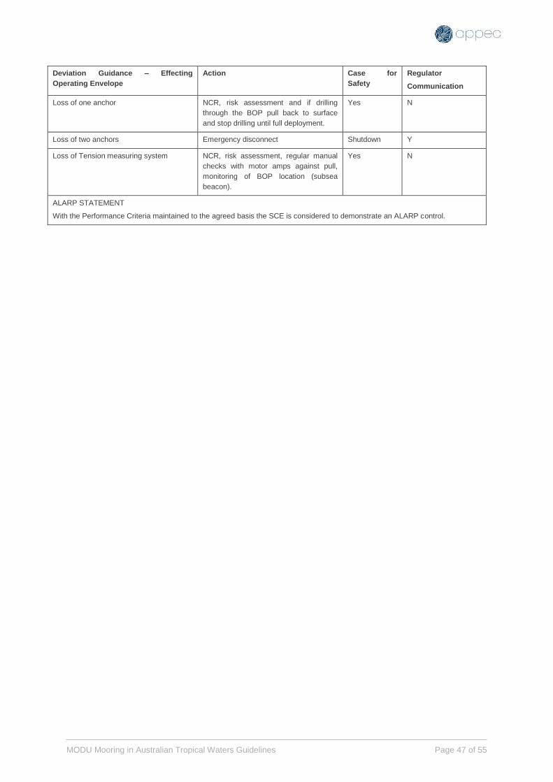
MODU Mooring in Australian Tropical Waters Guidelines Page 47 of 55
Deviation Guidance – Effecting
Operating Envelope
Action Case for
Safety
Regulator
Communication
Loss of one anchor NCR, risk assessment and if drilling
through the BOP pull back to surface
and stop drilling until full deployment.
Yes N
Loss of two anchors Emergency disconnect Shutdown Y
Loss of Tension measuring system NCR, risk assessment, regular manual
checks with motor amps against pull,
monitoring of BOP location (subsea
beacon).
Yes N
ALARP STATEMENT
With the Performance Criteria maintained to the agreed basis the SCE is considered to demonstrate an ALARP control.

MODU Mooring in Australian Tropical Waters Guidelines Page 48 of 55
APPENDIX B: MODU CYCLONE PREPARATION CHECKLIST
DISTRIBUTION LIST Rig Manger
Client Logistics
Attending Supply Vessels
Helicopter Operator
DATE
PAGES
Rig Name
IMO NUMBER
MMSI
OFFICIAL NUMBER
TOTAL FUEL
TOTAL POT WATER
TOTAL POB
SAFE AREA POSITION Lat Long Rig Heading
RIG DRAFT
Anchor #1 Tension Length
Anchor #2 Tension Length
Anchor #3 Tension Length
Anchor #4 Tension Length
Anchor #5 Tension Length
Anchor #6 Tension Length
Anchor #8 Tension Length
Anchor #9 Tension Length
Anchor #10 Tension Length
Anchor #11 Tension Length
Anchor #12 Tension Length

MODU Mooring in Australian Tropical Waters Guidelines Page 49 of 55
DEPARTURE ETA LAST
HELICOPTER
CONFIRM TRACKING SYTEM
OPERATIONAL AND WORKING WITH
RIG MANAGER ASHORE
Tested and Date
BACK UPPOWER FULL CHARGES FOR
TACKING SYSTEM
Power level
CONFIRM RECOVERY PLAN FOR
TOWING BRIDLE WITH ATTENDING
SUPPLY VESSEL.
INFORM OPERATORS WITIN 10 nm
WITH SURFACE FACILITIES AND SUB
SEA PIPELINS OF THE RIGS POSITION
AGREE ON MONITORING AND
REPORTING TRIGGERS WITH CLIENT
VESSELS IN ATTENDANCE

MODU Mooring in Australian Tropical Waters Guidelines Page 50 of 55
APPENDIX C: MODU MOORING FAILURE FLOW CHART

MODU Mooring in Australian Tropical Waters Guidelines Page 51 of 55
APPENDIX D: EXAMPLE MOORING BASIS OF DESIGN FORM
DESIGN CRITERIA:
Mooring Analysis & Design Standard
Exclusion Zones & Clearances to Infrastructure
Offset criteria
Dynamic or Quasi-Static Analysis
Analysis Type
6 or 3 degrees of freedom
GEOSPATIAL:
GDA94
Easting (m) Northing (m)
LAT Water Depth Nominal MODU Heading
Provided Data
Subsea infrastructure Layout
Bathymetry
METOCEAN:
Provided Data
Metocean Data Report/Tables
Storm Surge (m)
Max Tide (m)
GEOTECHNICAL
Provided Data
Site Specific Geotechnical Report
Anchor analysis
Geohazard analysis
Chain friction factor 1.0
SIGN-OFF
Project Engineer Metocean Authority Geotechnical Authority Drilling and Completions
Signature: Signature: Signature: Signature:
Date: Date: Date: Date:
As per API
Frequency Domain
Reviewed by Reviewed by Concurrence
Add Document Reference
Add Document Reference
Add Document Reference
API
Drill Centre Co-ordinates
Name: Name: Name: Name:
Compiled by
Rig Name:
MOORING ANALYSIS
BASIS OF DESIGN FORM
SCOPE OF WORK:
Well Name:
As per API
Date:
Drilling Contact:
Mooring Contact:
Dynamic
6 Degrees
Metocean Data Reference
Datum
Reference Drawing/Map
Projection (Zone)
Sample Text:
Perform an frequency domain dynamic mooring analysis and mooring pattern design, for Well-1 drill centre for full cyclone season
- Use Joint Maxima metocean data
- Consider conventional rig system. If conventional rig system fails, consider fibre prelay system
Perform quantitative risk assessment taking into consideration surrounding subsea and surface infrastructure.
Mooring analysis report is to include the following sensitivity studies for the governing loadcase:
- Time period sensitivity using referenced Tp/Hs contours
- Anchor location sensitivity to account for installation tolerance and anchor drag during cross-tensioning
Assume drag coefficient of 1.8 for wire and 2.6 for studlink chain as per DNV-RP-C205
Note that the presence of subsea infrastructure as per referenced drawing files
Reference Drawing/Map
Add Document Reference

MODU Mooring in Australian Tropical Waters Guidelines Page 52 of 55
APPENDIX E: MODU MOORING WORKFLOW GUIDANCE
The below aims to break down the MODU mooring workflow provided in Section 2.1 and offer guidance on
each step. The workflow is broken down into five steps as shown below:
Step 1 – Collect information
Collection of relevant and reliable MODU mooring information is critical to achieving a high level of certainty
in the final MODU mooring design. The lists below describe the relevant information for the mooring site and
the MODU vessel.
Metocean:
Is site specific metocean data available? If not, generic NWATW metocean data can be used which can be
extracted from RPS report [8]. The data outlined in the aforementioned report is considered to be
conservative. Therefore obtaining site specific data may improve the results of the mooring analysis.
Step 1 – Collect Information
Step 2 – Define MODU mooring risk category
Step 3 – Review risk mitigation measures and determine minimum metocean return period
Step 4 – Conduct Mooring Analysis
Step 5 – Conduct Mooring Risk Assessment

MODU Mooring in Australian Tropical Waters Guidelines Page 53 of 55
If obtaining site specific data, consideration should be given to the scope of the data which is to be supplied.
It may be beneficial to include joint maxima data, rather than independent extremes. This will also remove
some of the conservatism and improve results of mooring analysis.
See Section 3.3.3.1 and Section 6.1 for more information
Geotechnical:
Have soil samples been taken at and around the proposed drill centre? If so, is there a geotechnical report
available? Does the site have any shallow cemented calcarenite layers?
The purpose of the anchor analysis is to:
Determine the optimal anchor fluke angle
Predict anchor drag and embedment under load
Estimate the ultimate holding capacity of anchor under cyclic loading
See Section 7.2 for required information to run anchor capacity assessment.
Vessel Characteristics:
Relevant MODU data for mooring analysis is outlined in Section 3.3.3.1 and Section 5.
Mooring Equipment:
The purpose of collecting information on MODU mooring equipment is to determine if there is a high
certainty of MODU mooring equipment MBS values.
See Section 3.3.3.2, Section 8 and Section 9 for information on relevant information.
Step 2 – Determine MODU mooring risk category
Section 3 of the document provides guidance on characterising the MODU mooring risk as either: Low,
Medium or High.
The MODU mooring risk is determined by testing against three criteria:
1. Proximity of MODU (drill site) to high value assets (Consequence Test)
2. Season of operation (Likelihood Test)
3. Quality of information available (Risk Mitigation Test)
The first two tests provide an initial risk category. The risk category associated with close proximity mooring
can then be reduced by satisfying the third (Risk Mitigation) test. This is the only way that the risk category
can be reduced as per the guidance in this document.
The risk mitigation test is based on the information obtained in Step 1.
Step 3 – Review Risk Mitigation Measures and determine metocean Return Period
Each section of the document (Section 4 to Section 10) presents a table of risk mitigation measures which
are based on the MODU mooring risk category. It is recommended that the user of this guideline review the
risk mitigation tables and consider the mooring recommendations for the relevant MODU mooring risk
category. This is recommended be done early in the design stage.
Section 4.3 of the document makes recommendation on the minimum metocean return period with respect to
MODU mooring risk category. Satisfying the Risk Mitigation Tests (Section 3.3.3) and lowering the risk
category (for close proximity moorings) permits the metocean return period to be lowered.

MODU Mooring in Australian Tropical Waters Guidelines Page 54 of 55
Step 4 – Conduct Mooring Analysis
Section 5 of this report provides guidance on MODU mooring analysis.
If API criteria cannot be satisfied with conventional rig mooring equipment or prelay equipment for the
recommended metocean return period, consider:
1. Reduction of metocean return period as outlined in Step 2
2. Rescheduling drilling operations outside of cyclone season.
Step 5 – Conduct Risk Assessment
Section 4 of this report provides guidance on MODU mooring risk assessment.
If the result of the risk assessment shows that the risk is not tolerable, then further risk reduction measures
should be considered as per Step 3. When considering further risk reduction measures, the Operator and
Titleholder should be satisfied not adopting further risk reductions reduces the MODU mooring risk to as low
as reasonably practicable (ALARP).
ALARP needs to be demonstrated even if the MODU mooring risk is considered tolerable by company
standards. See Section 4.7.3 for more information on the demonstration of ALARP as defined by
NOPSEMA.

MODU Mooring in Australian Tropical Waters Guidelines Page 55 of 55
Appendix F: Feedback form
Feedback Form
Please complete details below and email to: [email protected]
Name:
Position/Title:
Email:
Company:
Phone:
Date:
Page Section no. Comments/Feedback