
Modifications to GPS Reference Station Antennas to Reduce Multipath
13
Modifications to GPS Reference Station Antennas to Reduce Multipath Aaron Kerkhoff, R. Benjamin Harris, Colin P. Petersen, Alex Pickard Applied Research Laboratories, The University of Texas at Austin BIOGRAPHY Aaron Kerkhoff is a Research Associate at the Applied Research Laboratories, The University of Texas at Austin (ARL:UT.) He received B.S degrees in both Electrical and Computer Engineering from the University of Missouri at Columbia in 1998 and M.S. and Ph.D. degrees in Electrical Engineering from the University of Texas at Austin in 2001 and 2008, respectively. R. Benjamin Harris is an Engineering Scientist at ARL:UT. He received a B.S. (1994) and Ph.D. (2008) in Aerospace Engineering from UT Austin and his M.S. in Aeronautics and Astronautics from Stanford (2000). Colin P. Petersen is an Engineering Scientist Associate at ARL:UT. He received a B.S. (2004) and M.S. (2006) in Electrical and Computer Engineering from UT Austin. Alex Pickard is an undergraduate student studying Me- chanical Engineering at the University of Texas at Austin. ABSTRACT The National Geospatial Intelligence Agency’s (NGA) GPS Monitor Station Network (MSN), consisting of 11 ground reference stations distributed throughout the world, is used collaboratively by NGA and the Air Force Op- erational Control Segment (OCS) to monitor the health of the GPS constellation, and to generate both broadcast and precise ephemeris products. Multipath caused by sig- nal scattering off objects in the vicinity of the antennas at these stations continues to be a dominant error source in MSN measurement observables. Both hardware-based and processing-based techniques are implemented in the MSN to mitigate this effect, however further suppression of mul- tipath is sought in order to improve system performance. This paper considers two different approaches to modi- fying the basic choke ring antenna design used in the MSN in order to reduce its reception of multipath. One approach consists of placing a large metallic ground plane directly beneath the antenna. This has the effect of shaping the an- tenna radiation patterns near and below the horizon so as to reduce reception of multipath signals from those directions. Another approach is to place a specific arrangement of RF absorbing foam around and beneath the base of the antenna in order to attenuate incoming multipath signals before they reach the antenna. Live-sky GPS receiver measurements were performed with a ground plane and then a novel ar- rangement of RF absorbing foam applied to a choke ring antenna. The results of a comprehensive analysis are pre- sented to demonstrate the degree to which each of these approaches reduce multipath error in raw code and carrier phase observables as well as in carrier phase smoothed ob- servables used in the GPS precise ephemeris production process. INTRODUCTION The Applied Research Laboratories at the University of Texas at Austin (ARL:UT) maintains, in partnership with the National Geospatial Intelligence Agency (NGA), a worldwide network of 11 unmanned Global Position- ing System (GPS) reference stations, known as the Mon- itor Station Network (MSN). NGA collects, processes, and distributes GPS observations, environmental data, and sta- tion health information from the MSN on a 24/7/365 basis. MSN data is used for a number of purposes by both NGA and the Air Force Operational Control Segment (OCS), in- cluding monitoring the quality and quantity of GPS satellite observables, and the generation of broadcast and precise ephemeris products [1]. Multipath error caused by signal scattering off objects near the antenna was an important consideration in the design of the MSN and multiple techniques were imple- mented to reduce its effect. At each MSN site, the an- tennas are elevated above nearby structures as much as is possible in order to minimize multipath components ema- nating from above the horizon. Choke ring antennas are used, which significantly attenuate multipath impinging from near the horizon and below the antenna. Processing 866 23rd International Technical Meeting of the Satellite Division of The Institute of Navigation, Portland, OR, September 21-24, 2010
Transcript of Modifications to GPS Reference Station Antennas to Reduce Multipath
Modifications to GPS Reference Station Antennas toReduce Multipath
Aaron Kerkhoff, R. Benjamin Harris, Colin P. Petersen, Alex PickardApplied Research Laboratories, The University of Texas at Austin
BIOGRAPHY
Aaron Kerkhoff is a Research Associate at the AppliedResearch Laboratories, The University of Texas at Austin(ARL:UT.) He received B.S degrees in both Electrical andComputer Engineering from the University of Missouri atColumbia in 1998 and M.S. and Ph.D. degrees in ElectricalEngineering from the University of Texas at Austin in 2001and 2008, respectively.
R. Benjamin Harris is an Engineering Scientist atARL:UT. He received a B.S. (1994) and Ph.D. (2008) inAerospace Engineering from UT Austin and his M.S. inAeronautics and Astronautics from Stanford (2000).
Colin P. Petersen is an Engineering Scientist Associateat ARL:UT. He received a B.S. (2004) and M.S. (2006) inElectrical and Computer Engineering from UT Austin.
Alex Pickard is an undergraduate student studying Me-chanical Engineering at the University of Texas at Austin.
ABSTRACT
The National Geospatial Intelligence Agency’s (NGA)GPS Monitor Station Network (MSN), consisting of 11ground reference stations distributed throughout the world,is used collaboratively by NGA and the Air Force Op-erational Control Segment (OCS) to monitor the healthof the GPS constellation, and to generate both broadcastand precise ephemeris products. Multipath caused by sig-nal scattering off objects in the vicinity of the antennas atthese stations continues to be a dominant error source inMSN measurement observables. Both hardware-based andprocessing-based techniques are implemented in the MSNto mitigate this effect, however further suppression of mul-tipath is sought in order to improve system performance.
This paper considers two different approaches to modi-fying the basic choke ring antenna design used in the MSNin order to reduce its reception of multipath. One approachconsists of placing a large metallic ground plane directlybeneath the antenna. This has the effect of shaping the an-
tenna radiation patterns near and below the horizon so as toreduce reception of multipath signals from those directions.Another approach is to place a specific arrangement of RFabsorbing foam around and beneath the base of the antennain order to attenuate incoming multipath signals before theyreach the antenna. Live-sky GPS receiver measurementswere performed with a ground plane and then a novel ar-rangement of RF absorbing foam applied to a choke ringantenna. The results of a comprehensive analysis are pre-sented to demonstrate the degree to which each of theseapproaches reduce multipath error in raw code and carrierphase observables as well as in carrier phase smoothed ob-servables used in the GPS precise ephemeris productionprocess.
INTRODUCTION
The Applied Research Laboratories at the Universityof Texas at Austin (ARL:UT) maintains, in partnershipwith the National Geospatial Intelligence Agency (NGA),a worldwide network of 11 unmanned Global Position-ing System (GPS) reference stations, known as the Mon-itor Station Network (MSN). NGA collects, processes, anddistributes GPS observations, environmental data, and sta-tion health information from the MSN on a 24/7/365 basis.MSN data is used for a number of purposes by both NGAand the Air Force Operational Control Segment (OCS), in-cluding monitoring the quality and quantity of GPS satelliteobservables, and the generation of broadcast and preciseephemeris products [1].
Multipath error caused by signal scattering off objectsnear the antenna was an important consideration in thedesign of the MSN and multiple techniques were imple-mented to reduce its effect. At each MSN site, the an-tennas are elevated above nearby structures as much as ispossible in order to minimize multipath components ema-nating from above the horizon. Choke ring antennas areused, which significantly attenuate multipath impingingfrom near the horizon and below the antenna. Processing
186623rd International Technical Meeting of the Satellite Division ofThe Institute of Navigation, Portland, OR, September 21-24, 2010
methods are implemented in the receiver tracking loops,which further reduce multipath error in the measured ob-servables. Finally, post-processing techniques are used toreduce the impact of multipath in data products, such asprecise ephemerides, derived from the raw measurements.
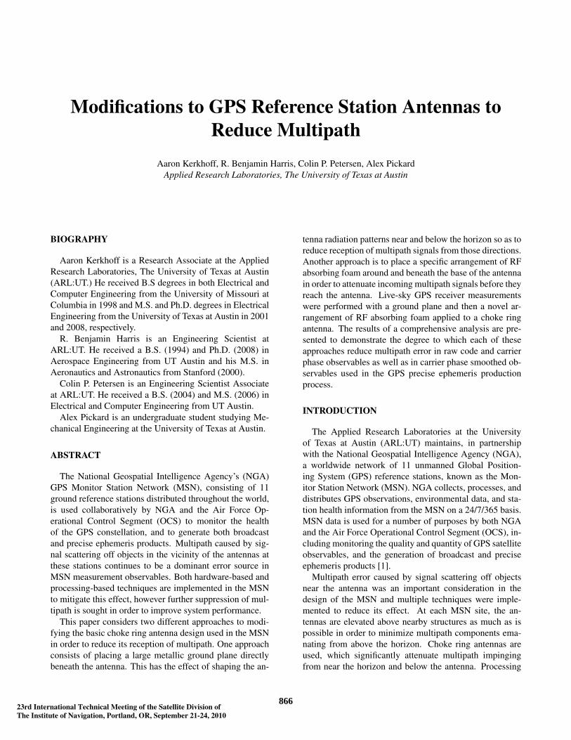
Despite these efforts, multipath continues to be a dom-inant error source in MSN measurement observables. Ananalysis was performed on multiple years of MSN data todetermine typical levels of multipath at each station. Fig. 1provides a visualization of the mean multipath error on theionospheric-free (L3) code multipath observable as a func-tion of elevation and azimuth angles relative to the antennaat the England MSN site. The method for creating this plotis described later in this paper. A number of concentricrings of alternating color (intensity) are evident in the plot,which are the wave interference pattern caused by the inter-action of the direct satellite signal and multipath scatteringoff the ground and other objects near the antenna. Note thatin some directions, the mean level of multipath in this ob-servable exceeds 1 m. Similar results were found in all ofthe other MSN stations.
Fig. 1 Mean multipath error on L3 code multipath ob-servable as a function of elevation (radial component) andazimuth (angular component) angles relative to EnglandMSN antenna. Note that the hole at the top of the plot isdue to the lack of satellite observability at those directions.
A common post-processing approach to mitigate mul-tipath is carrier phase smoothing of the code observable.This practice dates back as far as the Hatch filter [2], andis commonly used within GNSS receivers. NGA employs
carrier phase smoothing to condition all of the raw observ-able used in generating GPS precise ephemerides. How-ever, as demonstrated analytically in [3], multipath errorin the raw observables does indeed translate to a bias inthe smoothed observables. This is due to the fact that thesmoothing process acts like a low pass filter, and thus, lowfrequency error components cannot be removed.
Multipath error is a concern for other GNSS ground ref-erence station besides the MSN. In [4], an analysis of twoyears of data from over 200 International GNSS Service(IGS) and U.S. Continuously Operating Reference Station(CORS) network sites demonstrates that each site exhibitsa repeating pattern in post-fit carrier phase residuals due tomultipath and that the amplitude of this effect is strongly in-fluenced by the type of antenna used. A multi-year analysisof data from many IGS stations [5] suggests that near-fieldmultipath effects between the antenna and its surroundingsmay lead to annual variations in estimated site positionsat the 1 to 2 cm level. As indicated in [6], if not mitigated,multipath error would consume 90% of the error budget forthe Local Area Augmentation System (LAAS) used to as-sist civil aircraft landing. As such, a sophisticated antennadesign has been developed for LAAS to reduce multipathto an acceptable degree.
In the present study, we consider modifying the existingchoke ring antennas used at MSN stations so as to reducetheir reception of multipath, particularly those componentsemanating from near and below the horizon. One approachis to place a large metallic ground plane directly underneaththe choke ring antenna. The ground plane interacts withthe antenna in such a way as to modify the shape of the an-tenna radiation patterns. With the appropriate sizing of theground plane, it is possible to tailor the shape of patternsto reduce signal reception at lower angles, and thus reducemultipath. Such an approach was implemented at the U.S.Air Force GPS Monitor Stations as part of the Monitor Sta-tion Antenna Replacement (MSAR) project [7]. Anotherapproach is to place lossy material near the antenna in orderto attenuate impinging multipath signals before they reachthe antenna. A novel arrangement of outdoor-rated RF ab-sorbing foam placed around and underneath the antenna forthis purpose is described in this paper.
A measurement campaign was conducted to evaluate theefficacy of augmenting a choke ring antenna with a metal-lic ground plane or RF absorbing foam to mitigate mul-tipath. Long-term GPS data collections were performedwith each of these configurations using an equipment setupidentical to an MSN station. An analysis was performedon raw code and carrier phase receiver observables, as wellas carrier phase smoothed observables used in NGA’s pre-cise ephemeris production process to determine the degreeto which each configuration reduces multipath.
This paper is organized as follows: First, the groundplane and RF absorbing foam approaches to multipath mit-igation are described in greater detail. Then the test setup
286723rd International Technical Meeting of the Satellite Division ofThe Institute of Navigation, Portland, OR, September 21-24, 2010
used in measurements and the data analysis approach aredescribed. Next, the results of data analysis are given. Fi-nally, conclusions are made.
ANTENNA MODIFICATIONS
Since antennas at MSN sites are typically raised aboveall nearby objects and structures, it is assumed in this casethat multipath error is caused primarily by signals scatteredoff of objects below the antenna. In many cases, the domi-nant multipath component is caused by specular reflectionoff a large, relatively flat surface such as the ground or theroof of the building on which the antenna is mounted. Mul-tipath may also be caused by signal diffraction off of ob-jects in the vicinity of the antenna such as building edges,railings, or antenna stands.
It is necessary to consider the polarization of GPS signalsto determine the desired characteristics of the antenna. Thepolarization of a direct GPS signal is right hand circular(RHCP.) A GPS signal specularly-reflected off a horizontalsurface such as the ground exhibits left hand circular po-larization (LHCP) due to a 180 degree phase shift inducedby reflection; the exceptions to this are relatively low ele-vation angle reflections, occurring below Brewster’s angle,which exhibit RHCP due to an additional 180 degree phaseshift [8]. Diffracted signals are typically elliptically polar-ized, exhibiting both RHCP and LHCP components.
One way to reduce multipath reception is to shape theantenna radiation patterns to achieve high RHCP gain to-wards elevation angles above the horizon to receive thedirect component and low gain towards angles below thehorizon to reject multipath. Another approach is to takeadvantage of the change in signal polarization due to scat-tering by designing the antenna to have very low LHCPgain at all elevation angles both above and below the hori-zon.
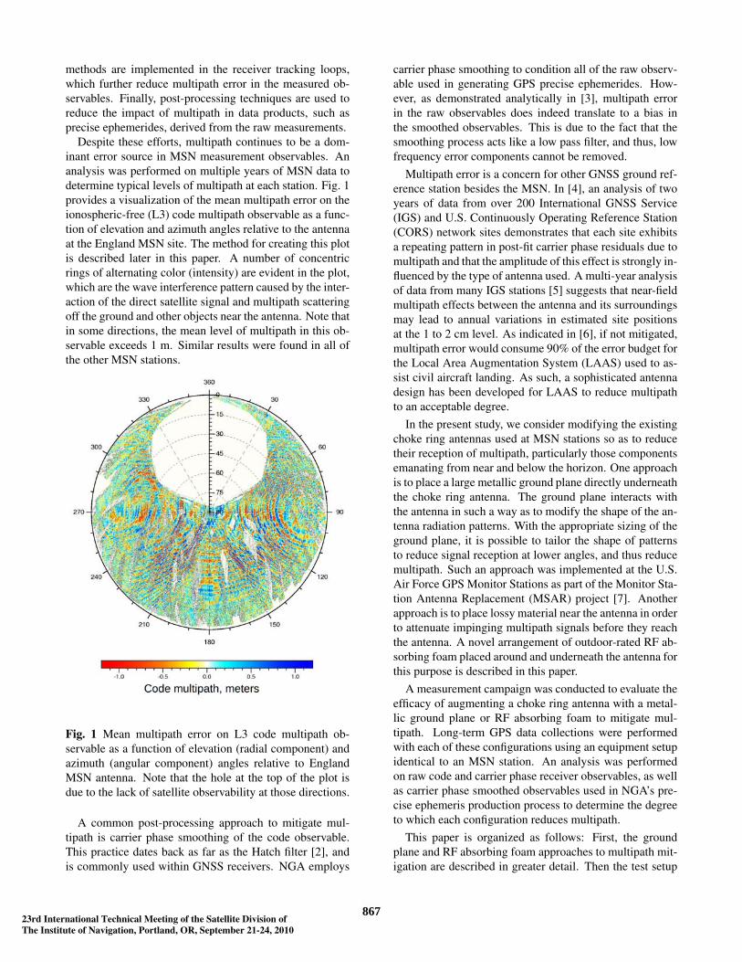
The commercial electromagnetic software HFSS [9] wasused to simulate the response of a typical choke ring an-tenna. The choke ring antenna radiation patterns, whichare shown in Fig. 2 for the L1 frequency, exhibit relativelylow LHCP gain over all elevation angles, high RHCP gainabove the horizon, and typically low RHCP gain below.However, just below the horizon, the slow rate of roll-offin the RHCP pattern leads to higher than desired gain inthose directions. To further reduce multipath reception ascompared with a typical choke ring antenna, it is desiredto increase the rate of RHCP pattern roll-off near the hori-zon and if possible, decrease LHCP reception, particularlybelow the horizon.
Ground Plane
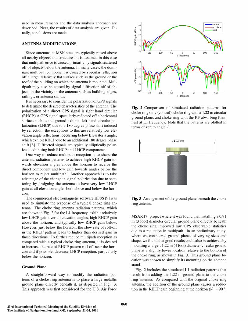
A straightforward way to modify the radiation pat-terns of a choke ring antenna is to place a large metallicground plane directly beneath it, as depicted in Fig. 3.This approach was first considered for the U.S. Air Force
-150 -100 -50 0 50 100 150-40
-30
-20
-10
0
10
θ (degrees)
RH
CP
gai
n (d
Bic
)
-150 -100 -50 0 50 100 150-50
-40
-30
-20
-10
θ (degrees)
LHC
P g
ain
(dB
ic)
controlgr. planenest
Fig. 2 Comparison of simulated radiation patterns forchoke ring only (control), choke ring with a 1.22 m circularground plane, and choke ring with the RF absorbing foamnest at L1 frequency. Note that the patterns are plotted interms of zenith angle, θ.
Fig. 3 Arrangement of the ground plane beneath the chokering antenna.
MSAR [7] project where it was found that installing a 0.91m (3 foot) diameter circular ground plane directly beneaththe choke ring improved raw GPS observable statisticsdue to a reduction in multipath. In an preliminary study,where we considered ground planes of varying sizes andshape, we found that good results could also be achieved bymounting a larger, 1.22 m (4 foot) diameter circular groundplane at a slightly lower location relative to the bottom ofthe choke ring, as shown in Fig. 3. This ground plane lo-cation was chosen to simplify its mounting on the antennastand.
Fig. 2 includes the simulated L1 radiation patterns thatresult from adding the 1.22 m ground plane to the chokering antenna. As compared with the original choke ringantenna, the addition of the ground plane causes a reduc-tion in the RHCP gain beginning at the horizon (|θ| = 90 ◦,
386823rd International Technical Meeting of the Satellite Division ofThe Institute of Navigation, Portland, OR, September 21-24, 2010
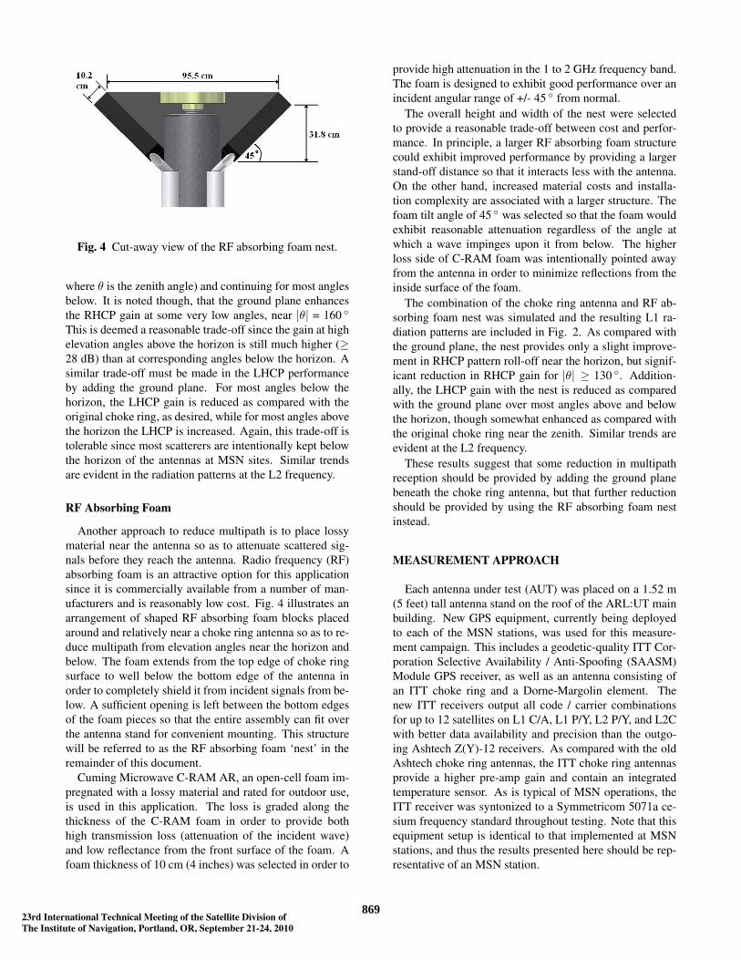
Fig. 4 Cut-away view of the RF absorbing foam nest.
where θ is the zenith angle) and continuing for most anglesbelow. It is noted though, that the ground plane enhancesthe RHCP gain at some very low angles, near |θ| = 160 ◦
This is deemed a reasonable trade-off since the gain at highelevation angles above the horizon is still much higher (≥28 dB) than at corresponding angles below the horizon. Asimilar trade-off must be made in the LHCP performanceby adding the ground plane. For most angles below thehorizon, the LHCP gain is reduced as compared with theoriginal choke ring, as desired, while for most angles abovethe horizon the LHCP is increased. Again, this trade-off istolerable since most scatterers are intentionally kept belowthe horizon of the antennas at MSN sites. Similar trendsare evident in the radiation patterns at the L2 frequency.
RF Absorbing Foam
Another approach to reduce multipath is to place lossymaterial near the antenna so as to attenuate scattered sig-nals before they reach the antenna. Radio frequency (RF)absorbing foam is an attractive option for this applicationsince it is commercially available from a number of man-ufacturers and is reasonably low cost. Fig. 4 illustrates anarrangement of shaped RF absorbing foam blocks placedaround and relatively near a choke ring antenna so as to re-duce multipath from elevation angles near the horizon andbelow. The foam extends from the top edge of choke ringsurface to well below the bottom edge of the antenna inorder to completely shield it from incident signals from be-low. A sufficient opening is left between the bottom edgesof the foam pieces so that the entire assembly can fit overthe antenna stand for convenient mounting. This structurewill be referred to as the RF absorbing foam ‘nest’ in theremainder of this document.
Cuming Microwave C-RAM AR, an open-cell foam im-pregnated with a lossy material and rated for outdoor use,is used in this application. The loss is graded along thethickness of the C-RAM foam in order to provide bothhigh transmission loss (attenuation of the incident wave)and low reflectance from the front surface of the foam. Afoam thickness of 10 cm (4 inches) was selected in order to
provide high attenuation in the 1 to 2 GHz frequency band.The foam is designed to exhibit good performance over anincident angular range of +/- 45 ◦ from normal.
The overall height and width of the nest were selectedto provide a reasonable trade-off between cost and perfor-mance. In principle, a larger RF absorbing foam structurecould exhibit improved performance by providing a largerstand-off distance so that it interacts less with the antenna.On the other hand, increased material costs and installa-tion complexity are associated with a larger structure. Thefoam tilt angle of 45 ◦ was selected so that the foam wouldexhibit reasonable attenuation regardless of the angle atwhich a wave impinges upon it from below. The higherloss side of C-RAM foam was intentionally pointed awayfrom the antenna in order to minimize reflections from theinside surface of the foam.
The combination of the choke ring antenna and RF ab-sorbing foam nest was simulated and the resulting L1 ra-diation patterns are included in Fig. 2. As compared withthe ground plane, the nest provides only a slight improve-ment in RHCP pattern roll-off near the horizon, but signif-icant reduction in RHCP gain for |θ| ≥ 130 ◦. Addition-ally, the LHCP gain with the nest is reduced as comparedwith the ground plane over most angles above and belowthe horizon, though somewhat enhanced as compared withthe original choke ring near the zenith. Similar trends areevident at the L2 frequency.
These results suggest that some reduction in multipathreception should be provided by adding the ground planebeneath the choke ring antenna, but that further reductionshould be provided by using the RF absorbing foam nestinstead.
MEASUREMENT APPROACH
Each antenna under test (AUT) was placed on a 1.52 m(5 feet) tall antenna stand on the roof of the ARL:UT mainbuilding. New GPS equipment, currently being deployedto each of the MSN stations, was used for this measure-ment campaign. This includes a geodetic-quality ITT Cor-poration Selective Availability / Anti-Spoofing (SAASM)Module GPS receiver, as well as an antenna consisting ofan ITT choke ring and a Dorne-Margolin element. Thenew ITT receivers output all code / carrier combinationsfor up to 12 satellites on L1 C/A, L1 P/Y, L2 P/Y, and L2Cwith better data availability and precision than the outgo-ing Ashtech Z(Y)-12 receivers. As compared with the oldAshtech choke ring antennas, the ITT choke ring antennasprovide a higher pre-amp gain and contain an integratedtemperature sensor. As is typical of MSN operations, theITT receiver was syntonized to a Symmetricom 5071a ce-sium frequency standard throughout testing. Note that thisequipment setup is identical to that implemented at MSNstations, and thus the results presented here should be rep-resentative of an MSN station.
486923rd International Technical Meeting of the Satellite Division ofThe Institute of Navigation, Portland, OR, September 21-24, 2010
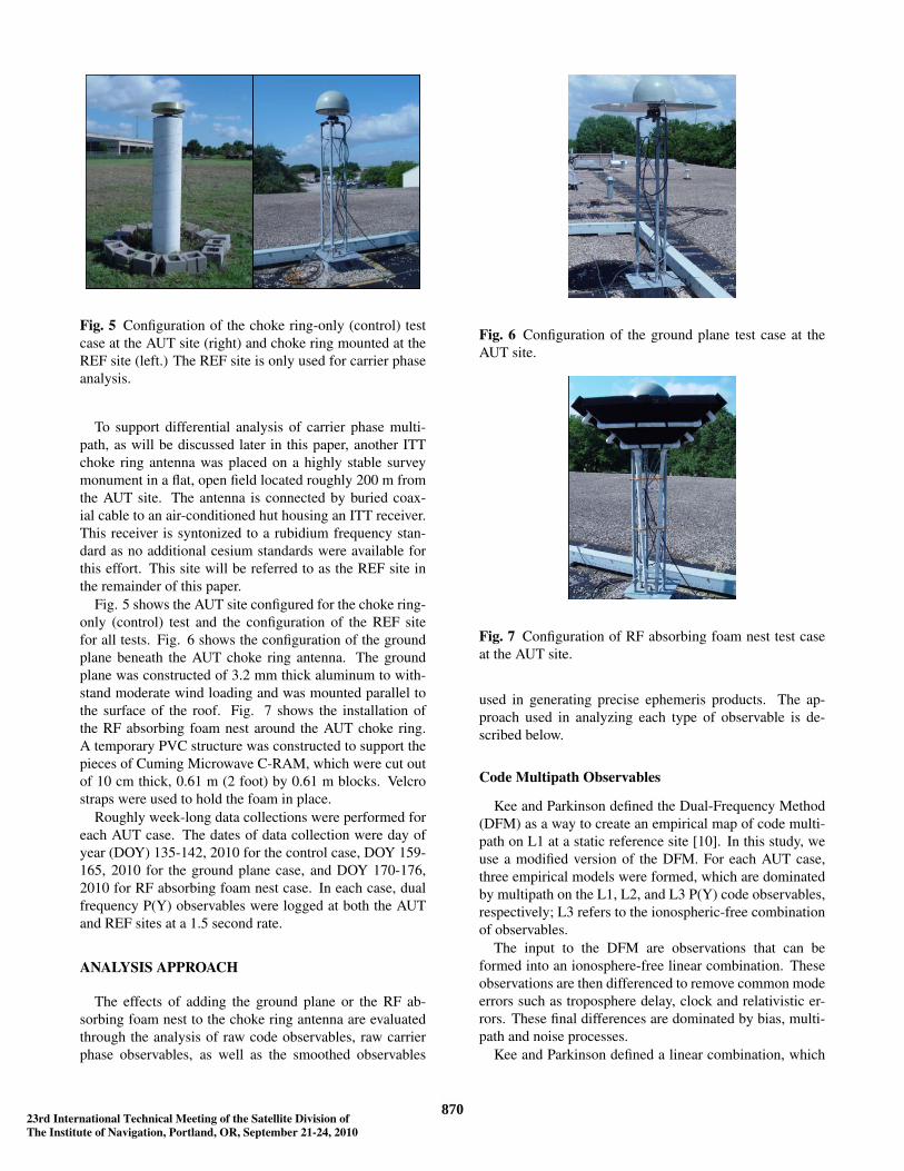
Fig. 5 Configuration of the choke ring-only (control) testcase at the AUT site (right) and choke ring mounted at theREF site (left.) The REF site is only used for carrier phaseanalysis.
To support differential analysis of carrier phase multi-path, as will be discussed later in this paper, another ITTchoke ring antenna was placed on a highly stable surveymonument in a flat, open field located roughly 200 m fromthe AUT site. The antenna is connected by buried coax-ial cable to an air-conditioned hut housing an ITT receiver.This receiver is syntonized to a rubidium frequency stan-dard as no additional cesium standards were available forthis effort. This site will be referred to as the REF site inthe remainder of this paper.
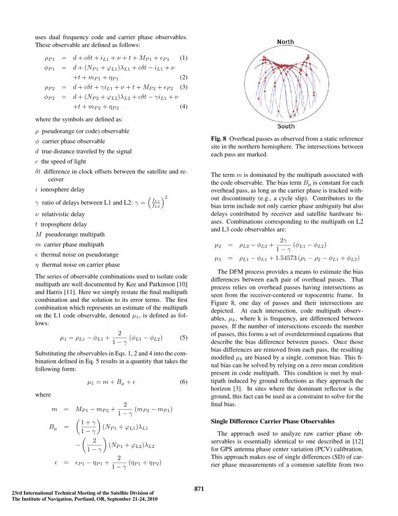
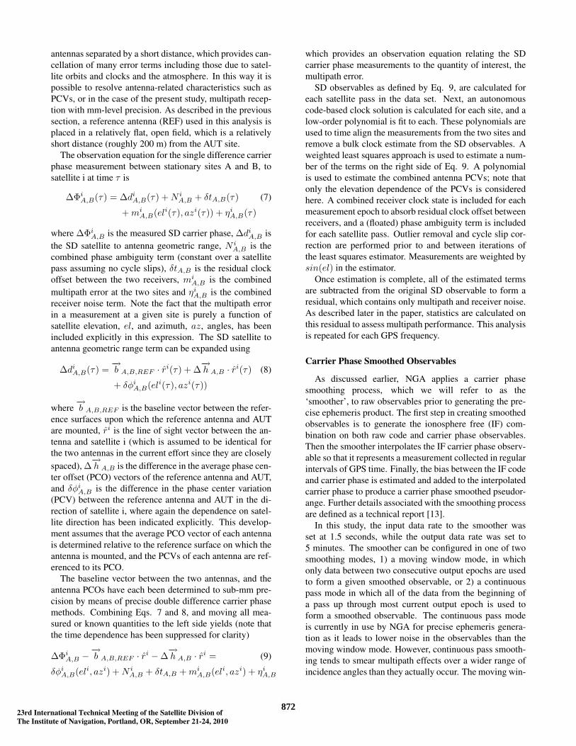
Fig. 5 shows the AUT site configured for the choke ring-only (control) test and the configuration of the REF sitefor all tests. Fig. 6 shows the configuration of the groundplane beneath the AUT choke ring antenna. The groundplane was constructed of 3.2 mm thick aluminum to with-stand moderate wind loading and was mounted parallel tothe surface of the roof. Fig. 7 shows the installation ofthe RF absorbing foam nest around the AUT choke ring.A temporary PVC structure was constructed to support thepieces of Cuming Microwave C-RAM, which were cut outof 10 cm thick, 0.61 m (2 foot) by 0.61 m blocks. Velcrostraps were used to hold the foam in place.
Roughly week-long data collections were performed foreach AUT case. The dates of data collection were day ofyear (DOY) 135-142, 2010 for the control case, DOY 159-165, 2010 for the ground plane case, and DOY 170-176,2010 for RF absorbing foam nest case. In each case, dualfrequency P(Y) observables were logged at both the AUTand REF sites at a 1.5 second rate.
ANALYSIS APPROACH
The effects of adding the ground plane or the RF ab-sorbing foam nest to the choke ring antenna are evaluatedthrough the analysis of raw code observables, raw carrierphase observables, as well as the smoothed observables
Fig. 6 Configuration of the ground plane test case at theAUT site.
Fig. 7 Configuration of RF absorbing foam nest test caseat the AUT site.
used in generating precise ephemeris products. The ap-proach used in analyzing each type of observable is de-scribed below.
Code Multipath Observables
Kee and Parkinson defined the Dual-Frequency Method(DFM) as a way to create an empirical map of code multi-path on L1 at a static reference site [10]. In this study, weuse a modified version of the DFM. For each AUT case,three empirical models were formed, which are dominatedby multipath on the L1, L2, and L3 P(Y) code observables,respectively; L3 refers to the ionospheric-free combinationof observables.
The input to the DFM are observations that can beformed into an ionosphere-free linear combination. Theseobservations are then differenced to remove common modeerrors such as troposphere delay, clock and relativistic er-rors. These final differences are dominated by bias, multi-path and noise processes.
Kee and Parkinson defined a linear combination, which
587023rd International Technical Meeting of the Satellite Division ofThe Institute of Navigation, Portland, OR, September 21-24, 2010
uses dual frequency code and carrier phase observables.These observable are defined as follows:
ρP1 = d+ cδt+ iL1 + ν + t+MP1 + εP1 (1)φP1 = d+ (NP1 + ϕL1)λL1 + cδt− iL1 + ν
+t+mP1 + ηP1 (2)ρP2 = d+ cδt+ γiL1 + ν + t+MP2 + εP2 (3)φP2 = d+ (NP2 + ϕL2)λL2 + cδt− γiL1 + ν
+t+mP2 + ηP2 (4)
where the symbols are defined as:
ρ pseudorange (or code) observable
φ carrier phase observable
d true distance traveled by the signal
c the speed of light
δt difference in clock offsets between the satellite and re-ceiver
i ionosphere delay
γ ratio of delays between L1 and L2: γ =(fL1fL2
)2
ν relativistic delay
t troposphere delay
M pseudorange multipath
m carrier phase multipath
ε thermal noise on pseudorange
η thermal noise on carrier phase
The series of observable combinations used to isolate codemultipath are well documented by Kee and Parkinson [10]and Harris [11]. Here we simply restate the final multipathcombination and the solution to its error terms. The firstcombination which represents an estimate of the multipathon the L1 code observable, denoted µ1, is defined as fol-lows:
µ1 = ρL1 − φL1 +2
1− γ(φL1 − φL2) (5)
Substituting the observables in Eqs. 1, 2 and 4 into the com-bination defined in Eq. 5 results in a quantity that takes thefollowing form:
µ1 = m+Bµ + ε (6)
where
m = MP1 −mP2 +2
1− γ(mP2 −mP1)
Bµ =(
1 + γ
1− γ
)(NP1 + ϕL1)λL1
−(
21− γ
)(NP1 + ϕL2)λL2
ε = εP1 − ηP1 +2
1− γ(ηP1 + ηP2)
Fig. 8 Overhead passes as observed from a static referencesite in the northern hemisphere. The intersections betweeneach pass are marked.
The term m is dominated by the multipath associated withthe code observable. The bias term Bµ is constant for eachoverhead pass, as long as the carrier phase is tracked with-out discontinuity (e.g., a cycle slip). Contributors to thebias term include not only carrier phase ambiguity but alsodelays contributed by receiver and satellite hardware bi-ases. Combinations corresponding to the multipath on L2and L3 code observables are:
µ2 = ρL2 − φL2 +2γ
1− γ(φL1 − φL2)
µ3 = ρL1 − φL1 + 1.54573 (ρ1 − ρ2 − φL1 + φL2)
The DFM process provides a means to estimate the biasdifferences between each pair of overhead passes. Thatprocess relies on overhead passes having intersections asseen from the receiver-centered or topocentric frame. InFigure 8, one day of passes and their intersections aredepicted. At each intersection, code multipath observ-ables, µk, where k is frequency, are differenced betweenpasses. If the number of intersections exceeds the numberof passes, this forms a set of overdetermined equations thatdescribe the bias difference between passes. Once thosebias differences are removed from each pass, the resultingmodified µk are biased by a single, common bias. This fi-nal bias can be solved by relying on a zero mean conditionpresent in code multipath. This condition is met by mul-tipath induced by ground reflections as they approach thehorizon [3]. In sites where the dominant reflector is theground, this fact can be used as a constraint to solve for thefinal bias.
Single Difference Carrier Phase Observables
The approach used to analyze raw carrier phase ob-servables is essentially identical to one described in [12]for GPS antenna phase center variation (PCV) calibration.This approach makes use of single differences (SD) of car-rier phase measurements of a common satellite from two
687123rd International Technical Meeting of the Satellite Division ofThe Institute of Navigation, Portland, OR, September 21-24, 2010
antennas separated by a short distance, which provides can-cellation of many error terms including those due to satel-lite orbits and clocks and the atmosphere. In this way it ispossible to resolve antenna-related characteristics such asPCVs, or in the case of the present study, multipath recep-tion with mm-level precision. As described in the previoussection, a reference antenna (REF) used in this analysis isplaced in a relatively flat, open field, which is a relativelyshort distance (roughly 200 m) from the AUT site.
The observation equation for the single difference carrierphase measurement between stationary sites A and B, tosatellite i at time τ is
∆ΦiA,B(τ) = ∆diA,B(τ) +N iA,B + δtA,B(τ) (7)
+miA,B(eli(τ), azi(τ)) + ηiA,B(τ)
where ∆ΦiA,B is the measured SD carrier phase, ∆diA,B isthe SD satellite to antenna geometric range, N i
A,B is thecombined phase ambiguity term (constant over a satellitepass assuming no cycle slips), δtA,B is the residual clockoffset between the two receivers, mi
A,B is the combinedmultipath error at the two sites and ηiA,B is the combinedreceiver noise term. Note the fact that the multipath errorin a measurement at a given site is purely a function ofsatellite elevation, el, and azimuth, az, angles, has beenincluded explicitly in this expression. The SD satellite toantenna geometric range term can be expanded using
∆diA,B(τ) =−→b A,B,REF · r̂i(τ) + ∆
−→h A,B · r̂i(τ) (8)
+ δφiA,B(eli(τ), azi(τ))
where−→b A,B,REF is the baseline vector between the refer-
ence surfaces upon which the reference antenna and AUTare mounted, r̂i is the line of sight vector between the an-tenna and satellite i (which is assumed to be identical forthe two antennas in the current effort since they are closelyspaced), ∆
−→h A,B is the difference in the average phase cen-
ter offset (PCO) vectors of the reference antenna and AUT,and δφiA,B is the difference in the phase center variation(PCV) between the reference antenna and AUT in the di-rection of satellite i, where again the dependence on satel-lite direction has been indicated explicitly. This develop-ment assumes that the average PCO vector of each antennais determined relative to the reference surface on which theantenna is mounted, and the PCVs of each antenna are ref-erenced to its PCO.
The baseline vector between the two antennas, and theantenna PCOs have each been determined to sub-mm pre-cision by means of precise double difference carrier phasemethods. Combining Eqs. 7 and 8, and moving all mea-sured or known quantities to the left side yields (note thatthe time dependence has been suppressed for clarity)
∆ΦiA,B −−→b A,B,REF · r̂i −∆
−→h A,B · r̂i = (9)
δφiA,B(eli, azi) +N iA,B + δtA,B +mi
A,B(eli, azi) + ηiA,B
which provides an observation equation relating the SDcarrier phase measurements to the quantity of interest, themultipath error.
SD observables as defined by Eq. 9, are calculated foreach satellite pass in the data set. Next, an autonomouscode-based clock solution is calculated for each site, and alow-order polynomial is fit to each. These polynomials areused to time align the measurements from the two sites andremove a bulk clock estimate from the SD observables. Aweighted least squares approach is used to estimate a num-ber of the terms on the right side of Eq. 9. A polynomialis used to estimate the combined antenna PCVs; note thatonly the elevation dependence of the PCVs is consideredhere. A combined receiver clock state is included for eachmeasurement epoch to absorb residual clock offset betweenreceivers, and a (floated) phase ambiguity term is includedfor each satellite pass. Outlier removal and cycle slip cor-rection are performed prior to and between iterations ofthe least squares estimator. Measurements are weighted bysin(el) in the estimator.
Once estimation is complete, all of the estimated termsare subtracted from the original SD observable to form aresidual, which contains only multipath and receiver noise.As described later in the paper, statistics are calculated onthis residual to assess multipath performance. This analysisis repeated for each GPS frequency.
Carrier Phase Smoothed Observables
As discussed earlier, NGA applies a carrier phasesmoothing process, which we will refer to as the‘smoother’, to raw observables prior to generating the pre-cise ephemeris product. The first step in creating smoothedobservables is to generate the ionosphere free (IF) com-bination on both raw code and carrier phase observables.Then the smoother interpolates the IF carrier phase observ-able so that it represents a measurement collected in regularintervals of GPS time. Finally, the bias between the IF codeand carrier phase is estimated and added to the interpolatedcarrier phase to produce a carrier phase smoothed pseudor-ange. Further details associated with the smoothing processare defined as a technical report [13].
In this study, the input data rate to the smoother wasset at 1.5 seconds, while the output data rate was set to5 minutes. The smoother can be configured in one of twosmoothing modes, 1) a moving window mode, in whichonly data between two consecutive output epochs are usedto form a given smoothed observable, or 2) a continuouspass mode in which all of the data from the beginning ofa pass up through most current output epoch is used toform a smoothed observable. The continuous pass modeis currently in use by NGA for precise ephemeris genera-tion as it leads to lower noise in the observables than themoving window mode. However, continuous pass smooth-ing tends to smear multipath effects over a wider range ofincidence angles than they actually occur. The moving win-
787223rd International Technical Meeting of the Satellite Division ofThe Institute of Navigation, Portland, OR, September 21-24, 2010
dow smoother, on the other hand, maintains the true spatialdependence of multipath errors, which is of particular in-terest in this study and simplifies the comparison of resultsfrom different AUTs. Therefore, moving window smooth-ing was used in this study. The evaluation of multipath ef-fects on smoothed observables generated using continuouspass smoothing will be addressed in a future study.
The quality of the smoother products can be assessedby differencing the smoothed pseudorange from a truthsource for pseudorange. This difference is referred to hereas an Observed Range Deviation (ORD). NGA Preciseephemerides are used as the truth source. The ORD cal-culations were computed using applications design specif-ically for this task, which are part of the GPS Toolkit(GPSTk), an open-source library and suite of applicationsfor GNSS data processing developed and maintained byARL:UT [14].
RESULTS
Code Multipath Observables
The DFM, as described in the previous section, was usedto generate observables corresponding to P(Y) code multi-path on the L1, L2, and L3 frequencies for each AUT case.These observables were generated at the full data collec-tion rate of 1.5 sec. For each AUT case and frequency, thecode multipath observables are sorted in terms of elevationangle, and binned statistics are calculated in 0.25 ◦ bins.
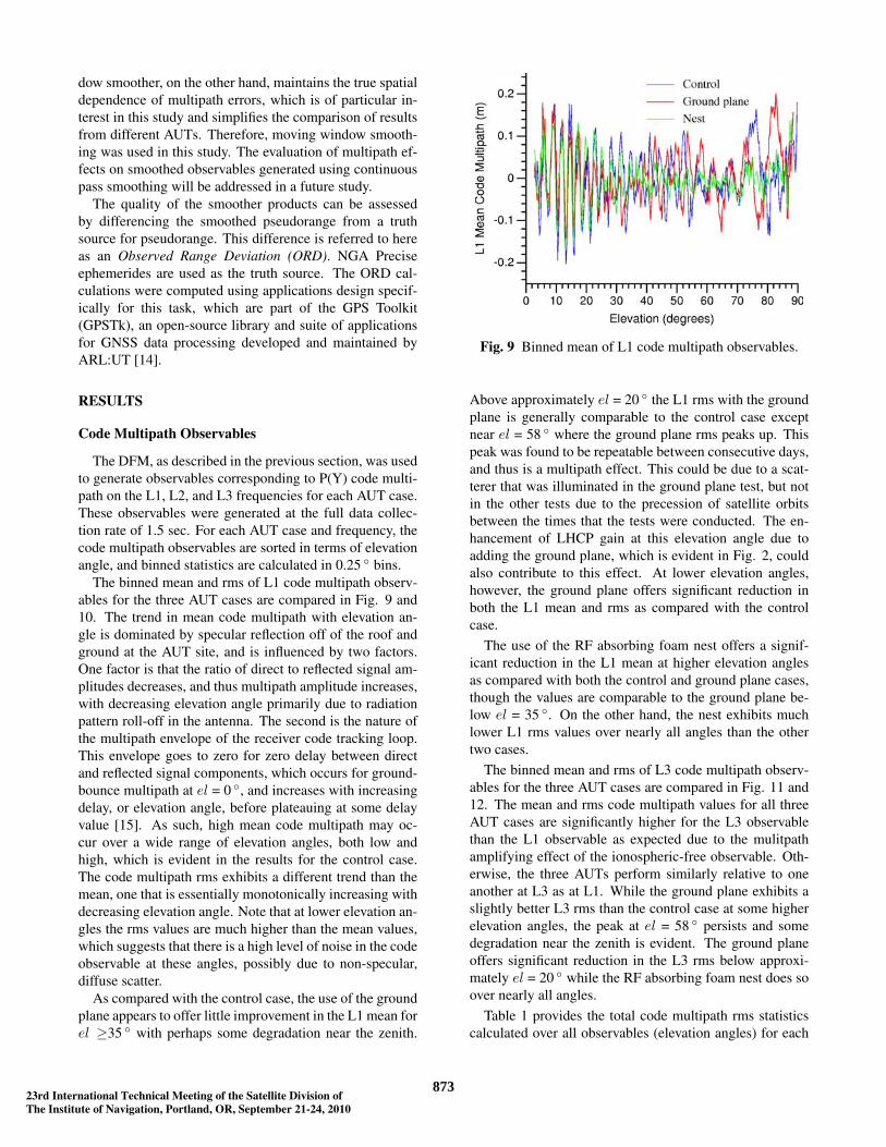
The binned mean and rms of L1 code multipath observ-ables for the three AUT cases are compared in Fig. 9 and10. The trend in mean code multipath with elevation an-gle is dominated by specular reflection off of the roof andground at the AUT site, and is influenced by two factors.One factor is that the ratio of direct to reflected signal am-plitudes decreases, and thus multipath amplitude increases,with decreasing elevation angle primarily due to radiationpattern roll-off in the antenna. The second is the nature ofthe multipath envelope of the receiver code tracking loop.This envelope goes to zero for zero delay between directand reflected signal components, which occurs for ground-bounce multipath at el = 0 ◦, and increases with increasingdelay, or elevation angle, before plateauing at some delayvalue [15]. As such, high mean code multipath may oc-cur over a wide range of elevation angles, both low andhigh, which is evident in the results for the control case.The code multipath rms exhibits a different trend than themean, one that is essentially monotonically increasing withdecreasing elevation angle. Note that at lower elevation an-gles the rms values are much higher than the mean values,which suggests that there is a high level of noise in the codeobservable at these angles, possibly due to non-specular,diffuse scatter.
As compared with the control case, the use of the groundplane appears to offer little improvement in the L1 mean forel ≥35 ◦ with perhaps some degradation near the zenith.
Fig. 9 Binned mean of L1 code multipath observables.
Above approximately el = 20 ◦ the L1 rms with the groundplane is generally comparable to the control case exceptnear el = 58 ◦ where the ground plane rms peaks up. Thispeak was found to be repeatable between consecutive days,and thus is a multipath effect. This could be due to a scat-terer that was illuminated in the ground plane test, but notin the other tests due to the precession of satellite orbitsbetween the times that the tests were conducted. The en-hancement of LHCP gain at this elevation angle due toadding the ground plane, which is evident in Fig. 2, couldalso contribute to this effect. At lower elevation angles,however, the ground plane offers significant reduction inboth the L1 mean and rms as compared with the controlcase.
The use of the RF absorbing foam nest offers a signif-icant reduction in the L1 mean at higher elevation anglesas compared with both the control and ground plane cases,though the values are comparable to the ground plane be-low el = 35 ◦. On the other hand, the nest exhibits muchlower L1 rms values over nearly all angles than the othertwo cases.
The binned mean and rms of L3 code multipath observ-ables for the three AUT cases are compared in Fig. 11 and12. The mean and rms code multipath values for all threeAUT cases are significantly higher for the L3 observablethan the L1 observable as expected due to the mulitpathamplifying effect of the ionospheric-free observable. Oth-erwise, the three AUTs perform similarly relative to oneanother at L3 as at L1. While the ground plane exhibits aslightly better L3 rms than the control case at some higherelevation angles, the peak at el = 58 ◦ persists and somedegradation near the zenith is evident. The ground planeoffers significant reduction in the L3 rms below approxi-mately el = 20 ◦ while the RF absorbing foam nest does soover nearly all angles.
Table 1 provides the total code multipath rms statisticscalculated over all observables (elevation angles) for each
887323rd International Technical Meeting of the Satellite Division ofThe Institute of Navigation, Portland, OR, September 21-24, 2010
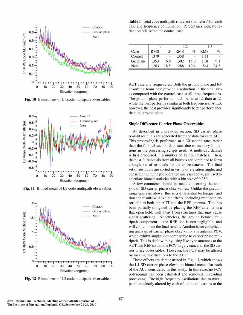
Fig. 10 Binned rms of L1 code multipath observables.
Fig. 11 Binned mean of L3 code multipath observables.
Fig. 12 Binned rms of L3 code multipath observables.
Table 1 Total code multipath rms error (in meters) for eachcase and frequency combination. Percentages indicate re-duction relative to the control case.
L1 L2 L3Case RMS % RMS % RMS %Control .379 - .358 - 1.11 -Gr. plane .353 6.9 .302 15.6 1.01 9.1Nest .283 18.5 .288 19.4 .841 24.3
AUT case and frequencies. Both the ground plane and RFabsorbing foam nest provide a reduction in the total rmsas compared with the control case at all three frequencies.The ground plane performs much better at L2 than at L1while the nest performs similar at both frequencies. At L3,however, the nest provides significantly better performancethan the ground plane.
Single Difference Carrier Phase Observables
As described in a previous section, SD carrier phasepost-fit residuals are generated from the data for each AUT.This processing is performed at a 30 second rate, ratherthan the full 1.5 second data rate, due to memory limita-tions in the processing scripts used. A multi-day datasetis first processed in a number of 12 hour batches. Then,the post-fit residuals from all batches are combined to forma single set of residuals for the entire dataset. The finalset of residuals are sorted in terms of elevation angle, andconsistent with the pseudorange analysis above, are used tocalculate binned statistics with a bin size of 0.25 ◦.
A few comments should be made concerning the anal-ysis of SD carrier phase observables. Unlike the pseudo-range analysis above, this is a differential technique, andthus the results will exhibit effects, including multipath er-ror, due to both the AUT and the REF antenna. This hasbeen partially mitigated by placing the REF antenna in aflat, open field, well away from structures that may causesignal scattering. Nonetheless, the ground bounce mul-tipath component at the REF site is non-negligible, andwill contaminate the final results. Another issue complicat-ing analysis of carrier phase observations is antenna PCV,which exhibit amplitudes comparable to carrier phase mul-tipath. This is dealt with by using like-type antennas at theAUT and REF so that the PCV largely cancel in the SD car-rier phase observables. However, the PCV may be alteredby making modifications to the AUT.
These effects are demonstrated in Fig. 13, which showsthe L1 SD carrier phase elevation-binned means for eachof the AUT considered in this study. In this case, no PCVpolynomial has been estimated and removed in residualprocessing. The high frequency oscillations due to multi-path, are clearly altered by each of the modifications to the
987423rd International Technical Meeting of the Satellite Division ofThe Institute of Navigation, Portland, OR, September 21-24, 2010

Fig. 13 L1 binned mean for raw carrier phase observablewhen no PCV is estimated in residual processing.
choke ring antenna. However, there is a common down-ward trend at low elevation angles in all three results. Thistrend is believed to be due to, primarily, the multipath at theREF site, which does not change between tests. Also, notethat a low frequency oscillation develops when the groundplane is added to the choke ring; this was determined tobe due to a change in the antenna PCV. This change inPCV between tests makes it difficult to compare the mul-tipath behavior of different AUT. Therefore, the residualprocessing was re-run including a 10th order polynomialto account for antenna PCV. This was done for each AUTcase for consistency. As is evident in the results givenbelow, this not only removes any trend due to PCV, butalso other low order trends in the data. This includes anybulk component of low elevation multipath at the AUT site.This, and the differential nature of the measurements likelymake the estimates reported here of the reduction in car-rier phase multipath provided by each antenna modificationsomewhat conservative.
The SD carrier phase elevation binned mean and rmsstatistics for the three AUTs (when a 10th order PCV poly-nomial is estimated in processing) are compared for theL1 and L3 frequencies in Fig. 14, 15, 16, and 17. Thestatistics for all three AUT exhibit a generally monoton-ically increasing trend with decreasing elevation. Thisis due primarily to the nature of the multipath envelopeof the receiver carrier phase tracking loop, which typi-cally exhibits increasing multipath error with decreasingdelay [15]. Note, however, that there is some decrease inthe statistics below el = 10 ◦. This is due to removing aPCV estimate from the residuals, which also removes a loworder multipath component, as discussed previously.
Similar trends in the mean statistic between differentAUT are evident in the SD carrier phase multipath observ-able as in the code observable. For both L1 and L3, thevariation in the mean using the ground plane is comparable
Fig. 14 L1 binned mean for raw carrier phase observablewhen a 10th order polynomial PCV is estimated in residualprocessing.
to the control case at higher elevation angles, but improvedat lower elevation angles. The mean using the nest, on theother hand, is improved relative to the control case overnearly all angles. At lower elevations, below el = 15 ◦ atL1, and el = 40 ◦ at L3, the improvement in the mean iscomparable for the ground plane and nest cases.
Some differences, however, are noted in the carrier phasestatistics as compared with the code statistics. Though theground plane exhibits improvement in the L1 SD carrierphase rms at lower elevation angles, it exhibits degradationabove el = 20 ◦. In the code results, however, the groundplane only exhibits degradation in the L1 rms statistic nearel = 58 ◦. This difference in the behavior of the two observ-ables is not yet understood. Also note that while the nest L1rms is much better than the control case at lower elevations,it appears to offer no improvement above el = 25 ◦; this isalso contrary to the code observable results. It is believedthat at higher elevation angles, a precision limit in the car-rier phase residual processing is being reached so that it isnot possible to resolve improvement due to the nest in sin-gle frequency results. This hypothesis is supported by theL3 rms statistics, which are somewhat better with the nestthan the control case at higher elevation angles. The am-plifying effect of the L3 observable causes the observablenoise to raise above the precision limit in residual process-ing.
Summary rms statistics calculated over the entire set ofresiduals (all elevation angles) for each AUT case and L1,L2, and L3 frequencies are given in Table 2. Consistentwith the results for the code observable, both the groundplane and the absorber nest offer an improvement in thetotal carrier phase residual rms at all frequencies consid-ered, but the nest performs somewhat better in each case.In general, the improvement to the carrier phase observableoffered by these antenna modifications is somewhat lower
1087523rd International Technical Meeting of the Satellite Division ofThe Institute of Navigation, Portland, OR, September 21-24, 2010
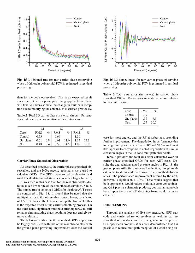
Fig. 15 L1 binned rms for raw carrier phase observablewhen a 10th order polynomial PCV is estimated in residualprocessing.
than for the code observable. This is an expected resultsince the SD carrier phase processing approach used herewill tend to under-estimate the change in multipath recep-tion due to modifying the antenna, as discussed previously.
Table 2 Total SD carrier phase rms error (in cm). Percent-ages indicate reduction relative to the control case.
L1 L2 L3Case RMS % RMS % RMS %Control 0.53 - 0.69 - 1.30 -Gr. plane 0.51 3.8 0.61 11.6 1.13 13.1Nest 0.48 9.4 0.59 14.5 1.08 16.9
Carrier Phase Smoothed Observables
As described previously, the carrier phase smoothed ob-servables, and the NGA precise ephemeris were used tocalculate ORDs. The ORDs were sorted by elevation andused to calculate binned statistics. A much larger bin size,10 ◦, was used in this case than for the raw observables dueto the much lower rate of the smoothed observables, 5 min.The binned rms of smoothed ORDs for the three AUT casesare compared in Fig. 18. It should first be noted that themultipath error in this observable is much lower, by a factorof 1.5 to 3, than in the L3 code multipath observable; thisis the expected effect of the carrier smoothing process. Onthe other hand, significant multipath error, up to 0.7 m, stillremains demonstrating that smoothing does not entirely re-move multipath.
The behavior exhibited in the smoothed ORDs appears tobe largely consistent with that of the raw observables, withthe ground plane providing improvement over the control
Fig. 16 L3 binned mean for raw carrier phase observablewhen a 10th order polynomial PCV is estimated in residualprocessing.
Table 3 Total rms error (in meters) in carrier phasesmoothed ORDs. Percentages indicate reduction relativeto the control case.
Case RMS %Control .39Gr. plane .37 6.5Nest .27 30.5
case for most angles, and the RF absorber nest providingfurther improvement. The degradation in performance dueto the ground plane between el = 50 ◦ and 60 ◦ as well as at80 ◦ appears to correspond to noted degradation at similarelevation angles in the L3 code multipath observable.
Table 3 provides the total rms error calculated over allcarrier phase smoothed ORDs for each AUT case. De-spite the degradations noted at some angles in Fig. 18, theground plane still offers an overall reduction, though mod-est, in the total rms multipath error in the smoothed observ-ables. The performance improvement offered by the nest,however, is significant, > 30%. These results suggest thatboth approaches would reduce multipath error contaminat-ing GPS precise ephemeris products, but that an approachbased upon the use of RF absorbing foam would be moreeffective.
CONCLUSIONS
Through the analysis of live sky measured GPS rawcode and carrier phase observables as well as carrier-smoothed observables used in the generation of preciseGPS ephemeris products, it has been demonstrated that it ispossible to reduce multipath reception of a choke ring an-
1187623rd International Technical Meeting of the Satellite Division ofThe Institute of Navigation, Portland, OR, September 21-24, 2010
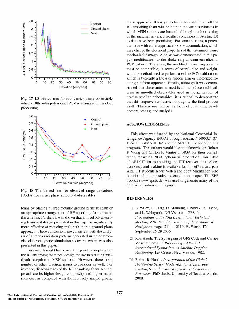
Fig. 17 L3 binned rms for raw carrier phase observablewhen a 10th order polynomial PCV is estimated in residualprocessing.
Fig. 18 The binned rms for observed range deviations(ORDs) for carrier phase smoothed observables.
tenna by placing a large metallic ground plane beneath oran appropriate arrangement of RF absorbing foam aroundthe antenna. Further, it was shown that a novel RF absorb-ing foam nest design presented in this paper is significantlymore effective at reducing multipath than a ground planeapproach. These conclusions are consistent with the analy-sis of antenna radiation patterns generated using commer-cial electromagnetic simulation software, which was alsopresented in this paper.
These results might lead one at this point to simply adoptthe RF absorbing foam nest design for use in reducing mul-tipath reception at MSN stations. However, there are anumber of other practical issues to consider as well. Forinstance, disadvantages of the RF absorbing foam nest ap-proach are its higher design complexity and higher mate-rials cost as compared with the relatively simple ground
plane approach. It has yet to be determined how well theRF absorbing foam will hold up in the various climates inwhich MSN stations are located, although outdoor testingof the material in varied weather conditions in Austin, TXto date have been promising. For some stations, a poten-tial issue with either approach is snow accumulation, whichmay change the electrical properties of the antenna or causemechanical damage. Also, as was demonstrated in this pa-per, modifications to the choke ring antenna can alter itsPCV pattern. Therefore, the modified choke ring antennamust be compatible, in terms of overall size and weight,with the method used to perform absolute PCV calibration,which is typically a live-sky robotic arm or motorized ro-tating platform approach. Finally, although it was demon-strated that these antenna modifications reduce multipatherror in smoothed observables used in the generation ofprecise satellite ephemerides, it is critical to demonstratethat this improvement carries through to the final productitself. These issues will be the focus of continuing devel-opment, testing, and analysis.
ACKNOWLEDGMENTS
This effort was funded by the National Geospatial In-telligence Agency (NGA) through contract# N00024-07-D-6200, task# 5101045 and the ARL:UT Honor Scholar’sprogram. The authors would like to acknowledge RobertF. Wong and Clifton F. Minter of NGA for their consul-tation regarding NGA ephemeris production, Jon Littleof ARL:UT for establishing the ITT receiver data collec-tion setup and making it available for this effort, and pastARL:UT students Kacie Walch and Scott Marmillion whocontributed to the results presented in this paper. The EPSToolkit (www.epstk.de) was used to generate many of thedata visualizations in this paper.
REFERENCES
[1] B. Wiley, D. Craig, D. Manning, J. Novak, R. Taylor,and L. Weingarth. NGA’s role in GPS. InProceedings of the 19th International TechnicalMeeting of the Satellite Division of the Institute ofNavigation, pages 2111 – 2119, Ft. Worth, TX,September 26-29 2006.
[2] Ron Hatch. The Synergism of GPS Code and CarrierMeasurements. In Proceedings of the 3rdInternational Symposium on Satellite DopplerPositioning, Las Cruces, New Mexico, 1982.
[3] Robert B. Harris. Incorporation of the GlobalPositioning System Modernization Signals intoExisting Smoother-based Ephemeris GenerationProcesses. PhD thesis, University of Texas at Austin,2008.
1287723rd International Technical Meeting of the Satellite Division ofThe Institute of Navigation, Portland, OR, September 21-24, 2010
[4] K.-D. Park, R.S. Nerem, M.S. Schenewerk, andJ.L.Davis. Site-specific multipath characteristics ofglobal IGS and CORS GPS sites. Journal ofGeodesy, 77(12):799–803, June 2004.
[5] J. Ray. Systematic errors in GPS position estimates,presented at the IGS Workshop 2006, May 2006.
[6] M. DiBenedetto M. Braasch F. van Graas C. BartoneD.B. Thornberg, D.S. Thornberg. The LAASintegrated multipath limiting antenna (IMLA). InProceedings of the 15th International TechnicalMeeting of the Satellite Division of the Institute ofNavigation, Portland, Oregon, September 2002.
[7] J. Cicero. Personal communication regarding theU.S. Air Force GPS Monitor Station AntennaReplacement (MSAR) project, July 22, 2010.
[8] Constantine A. Balanis. Advanced EngineeringElectromagnetics. John Wiley & Sons, New York,1989.
[9] HFSS software.http://www.ansoft.com/products/hf/hfss/.
[10] Changdon Kee and Bradford Parkinson. Calibrationof multipath errors on GPS pseudorangemeasurements. In Proceedings of the 7thInternational Technical Meeting of the SatelliteDivision of the Institute of Navigation, pages 353 –362, Salt Lake City, UT, September 20-23 1994.
[11] R. Benjamin Harris. Evaluation, Refinement andFusion of Software-Based Pseudorange MultipathMitigation Techniques. In Proceedings of the 15thInternational Technical Meeting of the SatelliteDivision of the Institute of Navigation, Portland,Oregon, September 2002.
[12] G. Mader. GPS antenna calibration at the NationalGeodetic Survey. GPS Solutions, 3(1):50–58, 1999.
[13] Description of the Smoothing Algorithm in the NGAMonitor Station Network. Technical report, AppliedResearch Laboratories, The University of Texas atAustin, May 1998.
[14] GPSTk website. http://www.gpstk.org/.
[15] R. van Nee. Spread-spectrum code and carriersynchronization errors caused by multipath andinterference. IEEE Trans. Aerospace and ElectronicSystems, 29(4):1359–1365, 1993.
1387823rd International Technical Meeting of the Satellite Division ofThe Institute of Navigation, Portland, OR, September 21-24, 2010