MODIFICATION OF GEAR MANUFACTURING PROCESSES OF QUILL SHAFT OF TURBO JET ENGINE
106
CHAPTER 1 INTRODUCTION 1.0 INTRODUCTION Hindustan Aeronautics Limited (HAL) was founded way back 1940 by a visionary Seth Shri Walchand Hirachand Aircraft Limited at Bangalore in association with the erstwhile princely state of Mysore. Govt. of India became one of its shareholders in March 1941 and took over the management in 1942. The present day Hindustan Aeronautics Limited, a Public Sector Undertaking (PSU), under Ministry of Defence and fully owned by Govt. of India was formally formed on Manufacturing Dept. with Hindustan Aeronautics Limited. Today, HAL is the largest PSU under Dept. of Defence Production, GOI and is declared as “Navratna” (Category-1) company. HAL has emerged as a premier 1
description
MODIFICATION OF GEAR MANUFACTURING PROCESSES OF QUILL SHAFT OF TURBO JET ENGINE....Final year project done in HAL, Bengaluru
Transcript of MODIFICATION OF GEAR MANUFACTURING PROCESSES OF QUILL SHAFT OF TURBO JET ENGINE

CHAPTER 1
INTRODUCTION
1.0 INTRODUCTION
Hindustan Aeronautics Limited (HAL) was founded way back 1940 by a
visionary Seth Shri Walchand Hirachand Aircraft Limited at Bangalore in
association with the erstwhile princely state of Mysore. Govt. of India became one
of its shareholders in March 1941 and took over the management in 1942.
The present day Hindustan Aeronautics Limited, a Public Sector
Undertaking (PSU), under Ministry of Defence and fully owned by Govt. of India
was formally formed on Manufacturing Dept. with Hindustan Aeronautics Limited.
Today, HAL is the largest PSU under Dept. of Defence Production, GOI and
is declared as “Navratna” (Category-1) company. HAL has emerged as a premier
defence production industry of the country and is fully owned by the Govt. of
India, Ministry of Defence.
HAL, with its wide spectrum of expertise in design, development and
manufacture of aircraft, helicopters, engines, accessories and avionics, has
emerged as a major aeronautical complex in Asia. HAL has nineteen production/
overhaul/ service Divisions well supported nine co-located R & D centers.
1

HAL’s mission is “To become a globally competitive aerospace industry
while working as instrument for achieving self-reliance in design, manufacture and
maintenance of aerospace equipment, civil transport aircraft, helicopters and
missiles and diversifying to related areas, managing the business on commercial
line in a climate of growing professional competence”.
The core business of HAL includes:
Design and development of fixed and rotary wing aircraft, Avionics and
Accessories.
Manufacture, maintenance, repair and overhaul of:
Fighter, Transport and Trainer aircraft
Helicopters
Aero-Engines
Avionics
Ground support equipment
Manufacture of structural components for satellites and launch vehicles.
Development of aeronautical software
HAL, over the last six decades, has grown progressively into an integrated
Aerospace organisation with its indigenous design & development of Advanced
Light Helicopter (ALH- Dhruv), Intermediate Jet Trainer (IFT), Light Combat
Aircraft (LCA-Tejas).
The on-going major projects & programmes include ALH (both in military
& civil roles). IJT, LCA, Pilotless Target Aircraft (PTA), S30MK, Hawk-
Advanced Jet Trainer.
2

Aligning with the emerging future requirements, HAL has conceptualised
the indigenous development of Light Combat Helicopter (LCH), Combat Air
Trainer (CAT) as well as naval & trainer versions of LCA.
HAL has three joint venture companies:
BAE-HAL Software Limited for development of aeronautical software
Indo-Russian Aviation Limited (IRAL) for spares & Services of Russian origin
aircraft/engines/accessories
Snecma- HAL Aerospace Private Limited for production of aero-engine
components. Further, several co-production and Joint Ventures with international
participation are under consideration, aiming to enhance business and to upgrade
technology.
HAL continues to maintain highest credit rating for long term and shirt term
debt programmes, which is a testimony of the financial soundness of HAL.
HAL as an organization, has won several awards for its achievements in the
field of aeronautics like world Quality Commitment International Star” in Platinum
category by Business Initiative Directions, Golden Peacock Award for Innovation
etc. in recognition of HAL’s contribution in Quality, Leadership, Technology and
Innovation.
1.1 HAL MANAGEMENT ACADEMY (HMA)
HMA is a premier training institute equipped with state-of-art training
facilities & highly qualified faculty. HMA undertakes various training programs
for the executives on regular basis for continued enhancement of managerial
knowledge and leadership.
3

1.2 BANGALORE COMPLEX
1.2.1 AIRCRAFT DIVISION
The product profile of the division presently include Jaguar Strike aircraft,
PTA (Lakshya), Composite/ Metal Drop tanks Dornier 228 Landing Gears.
Facilities for manufacture of HAWK-Advance Jet trainer are under establishment.
The division exports high precision aircraft components and sub-assemblies like
Airbus A320/A321 forward Pax Doors, Boeing 757 OWX Doors and other
structure work packages.
1.2.2 ENGINE DIVISION
Engine Division is presently engaged in manufacture of Adour Mk 871 &
811, Garrett TPE 331-5 Artouste IIIB & Shakti, GTSU, PTAE. The divisions also
undertake repair and overhaul of Adour Mk 811, Adour MK 804E, Garrett, Dart,
Gnome, Orpheous, Artouste IIIB and Avon MK 1/ MK 109 engines.
1.2.3 OVERHAUL DIVISION
The present activities of Overhaul division includes Major servicing of Kiran MK
I/IA, Kiran MK II, Jaguar Strike & Trainer and Major inspection of Mirage 2000
Fighter & Trainer, Overhaul & repair of Lycoming (HPT-32 & Islander) engines,
Overhaul and repair/ servicing of accessories.
1.2.4 AEROSPACE DIVISION
The Division undertakes production of light alloy structures for the Polar Satellite
Launch Vehicle (PSLV), Geo Stationary Launch Vehicle (GSLV), Indian Remote
sensing Satellite (IRS), Indian National Satellite (INSAT) and CRYO structures.
4

1.2.5 FOUNDARY & FORGE DIVISION
The activities of the division includes development and manufacture of
Aluminum and Magnesium base alloys and indigenous development of castings
and forgings in ferrous and Non- ferrous alloys, rolled rings, brake pads and rubber
products for critical applications for the Aeronautics, Space, Defence, Locomotive,
Earthmover and other industries.
1.2.6 AIRPORT SERVICES CENTER
Presently Airport Services Center is providing the technical services of Air
Traffic Control, maintenance of Runway and navigation/ landing aids and various
other allied services of HAL Airport, which is the third busiest airport in the
country.
1.2.7 INDUSTRIAL & MARINE GAS TURBINE (IMGT) DIVISION
The major activities of IMGT Division presently are manufacture of LM
2500 (Marine) engines and repair/overhaul of Industrial Avon, Allison & LM 2500
(Industrial) engines. A dedicated LCA-LSP unit has been set up to handle LCA-
Tejas production. Limited series production of LCA has commenced.
1.3 DESIGN COMPLEX
1.3.1 AIRCRAFT R & D CENTER (ARDC)
ARDC has full spectrum of expertise in all facets of aircraft design,
prototype manufacturing and extensive testing facilities backed by rich in-service
experience of more than five decades. On-going projects include indigenous design
& development of Intermediate Jet Trainer (IJT) & Light Combat Aircraft (LCA).
5

1.3.2 ROTARY WING R & D CENTER (RWRDC)
RWRDC undertakes full range of design tasks for civil & military
helicopters. It has extensive facilities for design & development, testing & analysis
of structure/transmission system/integration of engine/avionics as well as
accessories.
RWRDC is the nodal agency for successful design & development of Dhruv
ALH for wide range of military & civil applications. On-going projects include
development of Light Combat Helicopter (LCH).
1.3.3 HELICOPTER DIVISION
The present activities of the division include series production of Advanced
Light Helicopter (Dhruv), manufacture & overhaul of Cheetah (SA-315 Lama),
Chetak (Alouette III), Lancer, Cheetal and Chetan helicopters. Its service to
customer includes logistic and technical support including training. Barrackpore
Branch Factory, attached to Helicopter Division, primarily undertakes Major
Servicing of Cheetah and Chetak Helicopters.
1.3.4 AIRCRAFT DIVISION, NASIK
The Division is currently engaged in manufacture of SU-30 MKI aircraft,
spares of MiG21 series, MIG 27M, MIG 23 & MIG 29 aircraft.
The Division is also involved in manufacture /repair/overhaul of Undercarriages of
ALH, LCA and Mirage-2000.
6

1.3.5 AIRCRAFT OVERHAUL DIVISION, NASIK
The Division is currently engaged in repair/overhaul of MiG-21 aircraft
variants/ MIG-27M aircraft and their aggregates & retables. The Division has
undertaken series up gradation of MiG-21 BIS and MiG-27.
1.3.6 ENGINE DIVISION, KORAPUT
Present activities of the division include manufacture of R-25 series engines
of MiG-21BIS and overhaul of R-11 series engines of MiG-21 FL/MiG-21M, R-
29B engines for/ MIG- 27M aircraft and RD-33 engines of MiG-29 aircraft. The
division also undertakes development & manufacture of forgings & castings for
aeronautical & industrial applications.
1.3.7 SUKHOI ENGINE DIVISION, KORAPUT
A separate Division has been set up for manufacture an AL 31FP engine for
SU-30MKI aircraft. Production programme for AL 31FP commenced in 2004-05
1.4 ACCESSORIES COMPLEX
1.4.1 ACCESSORIES DIVISION, LUCKNOW
The manufacturing range of the division can be grouped under 3 categories.
Mechanical & Hydro Mechanical Accessories
Engine Accessories
Instrument Accessories
The division is also manufacturing a wide range of Ground Support equipment
like Ground Power Unit, Hydraulic Trolley, Weapon loading Trolley,
Transportation Trolley, Alert Trolley, Test Equipment etc
7

1.4.2 AVIONICS DIVISION, HYDERABAD
Presently, the product profit of the division includes Precision Apporach
Radar, INCOM, Airborne Rader, Identification of Friend or Foe (IFF), Automatic
Direction Finder (ADF), HFSSB, VHF/ UHF, Aircraft Battery and Ceramic Brake
Pads.
1.4.3 ACIONICS DIVISION, KORWA
Avionics Division Korwa is presently involved in a advanced avionics
systems like Inertial Navigation System (INS), s Combined Map and Electronic
Display (COMED), Head Up Display & Weapon Aiming Computer (HUDWAC),
Laser Ranger and Marked Target Seeker (LRMTS), Auto stabilizer and Flight Data
Recorder (FDR).
The Division has also established the facilities for Depot Level Maintenance
facilities for Digital Map Generator (DMG), Head UP Display (HUD) for Jaguar
and SU-30 aircraft & production Facilities for manufacture of Multi-Function
Display (MFD) for SU-30 MKI aircraft.
1.4.4 TRANSPORT AIRCRAFT DIVISION (TAD), KANPUR
Currently, the activities of TAD-Kanpur Division include manufacturing and
overhaul of DO-228 aircraft in addition to overhaul of HS-748 and HPT-32 aircraft
and their rotables. HAL Detachment Agra, attached to TAD-Kanpur is involved in
servicing of AN-32 aircraft and overhaul of Canberra aircraft
8

1.4.4 HAL CUSTOMERS
Defence Customers: Indian air force, Indian navy, Indian army
Civil Customers: Coast Guard, Border Security Force, Corporate Section,
State Governments
Exports: Honeywell, Rolls Royce, Turbomeca etc.
1.5 INTRODUCTION ON GEARS
Gears are machine elements that transmit motion by means of successively
engaging teeth. The gear teeth act like small levers. A gear is a rotating machine
part having teeth which mesh with another toothed part in order to transmit power,
torque, and motion or to change speed or direction.
1.5.1 THE LAW OF GEARING
A primary requirement of gears is the constancy of angular velocities or
proportionality of position transmission, Precision instruments require positioning
fidelity. High speed and/or high power gear trains also require transmission at
constant angular velocities in order to avoid severe dynamic problems. Constant
velocity (i.e. constant ratio) motion transmission is defined as “conjugate action”
of the gear tooth profiles. A geometric relationship can be derived for the form of
the tooth profiles to provide conjugate action, which is summarized as the Law of
Gearing as follows:
9

“A common normal to the tooth profiles at their point of contact must, in all
positions of the contacting teeth, pass through a fixed point on the line-of-centers
called the pitch point.” Any two curves or profiles engaging each other and
satisfying the law of gearing are conjugate Curves.
Fig 1.0 Law of gearing
1.5.2 INVOLUTE AND CYCLOIDAL PROFILES
Gear profiles that do not satisfy this law will not have a constant angular
velocity ratio. In other words the driving pinion could travel at a constant rpm but
the driven wheel would speed up and slow down instead of rotating smoothly. This
would cause all kinds of problems.
1.5.3 GEAR TEETH PROFILE
A profile is one side of a tooth in a cross section between the outside circle
and the root circle. Usually a profile is the curve of intersection of a tooth surface
and a plane or surface normal to the pitch surface, such as the transverse, normal, 10

or axial plane. The fillet curve (root fillet) is the concave portion of the tooth
profile where it joins the bottom of the tooth space. A non- fluctuating velocity
ratio is dependent on the profile of the teeth. Friction and wear between two gears
is also dependent on the tooth profile.
There are a great many tooth profiles that will give a constant velocity ratio,
and in many cases, given an arbitrary tooth shape, it is possible to develop a tooth
profile for the mating gear that will give a constant velocity ratio. However, two
constant velocity tooth profiles have been by far the most commonly used in
modern times.
Fig 1.1 Spur gear profile
1.5.4 INVOLTE TOOTH FORM
Imagine unwinding a spool of thread. The arc at the end of the thread forms
an involute curve. Involute gears are economical to make because the cutters used
to make the gears are straight. Another advantage is that the center distance
between the gears can be changed and the gears will still transmit a constant
velocity
11

Fig 1.2 Involute tooth form
.
1.5.5 INVOLUTE GEARS IN ACTION
Fig 1.3 Involute gears in action
This shows a pair of full fitting involute gears. Gears found in machines or
purchased from a catalogue would have tooth form like this.
o Very little backlash.
o Three teeth engaged at all times.
o Lots of friction.
12

1.5.6 CYCLOIDAL TOOTH FORM
Cycloidal tooth forms are used primarily in clocks for a number of reasons.
o Less sliding friction.
o Less wear.
o Easier to achieve higher gear ratios without tooth interference.
Two generating circles roll on the pitch circle to trace the cycloidal tooth
profile. The outside circle traces the "face" of the gear tooth. The inside circle
traces the "flank" of the gear tooth. Clock gears have a further refinement. Radial
lines are drawn from the center of the gear tangent to the flank. The flank area is
then removed along these lines to reduce friction.
1.5.7 CYCLOIDAL GEARS- MODIFIED FLANK
This cycloidal gear set has the flanks removed. See how the gears do not
engage until the pitch circles nearly come in contact. The length of time the gears
are touching is reduced too. Also see that the only one pair of teeth is engaged at a
time. As one tooth starts to drive, the previous driver loses contact. The teeth are
narrower and easier to make. Backlash is not a problem for clocks because the
gears always turn in one direction.
13

Fig 1.4 Cycloidal Gears- Modified Flank
Fig 1.5 Three teeth engaged at all times in cycloidal system
14

1.6 TERMINOLOGY IN GEAR MANUFACTURING PROCESS
Pitch Surface: The surface of the imaginary rolling cylinder (cone etc.) that
the toothed gear may be considered to replace.
Pitch circle: Right section of the pitch surface.
Addendum circle: The circle bounding the ends of the teeth, in a right
section of the gear.
Dedendum circle (root circle): The circle bounding the spaces between the
teeth, in a right section of the gear.
15

Addendum: The radial distance between the pitch circle and the addendum
circle.
Dedendum: The radial distance between the pitch circle and the root circle.
Clearance: The difference between the dedendum of one gear and the
addendum of the mating gear.
Face of a tooth: The part of the tooth surface lying outside the pitch surface.
Flank of a tooth: Part of the tooth surface lying inside the pitch surface.
Circular thickness (tooth thickness): The thickness of the tooth measured
on the pitch circle. It is the length of an arc and not a length of a straight
line.
Tooth space: The distance between the adjacent teeth measured on the pitch
circle.
Circular pitch (p): The width of a tooth and a space, measured on the pitch
circle.
Diametral pitch (P): The number of teeth of a gear per inch of its pitch
diameter. A toothed gear must have an integral number of teeth. Circular
pitch therefore equals the pitch circumference divided by the number of
teeth. The diametral pitch is the number of teeth divided by the pitch
diameter.
Module (m): Pitch diameter divided by number of teeth. The pitch diameter
is usually specified in inches or millimeters, in the former case the module is
inverse of diametral pitch.
Fillet: The small radius that connects the profile of a tooth to the root circle.
Pinion: The smallest of any pair of mating gears. The largest of the pair is
called simply the gear.
16

Velocity ratio: The ratio of number of revolutions of the driving (or input)
gear to the number of revolutions of the driven (or output) gear, in a unit of
time.
Pitch point: The point of tangency of the pitch circles of a pair of mating
gears.
Common tangent: The line tangent to the pitch circle at the pitch point.
Pressure angle: The angle between the common normal at the point of tooth
contact and the common tangent to the pitch circles. It is also the angle
between the line of action and the common tangent.
Base circle: An imaginary circle used in involute gearing to generate the
involutes that forms the tooth profiles
Working depth (hk): Working depth is the depth of engagement of two
gears; that is, the sum of their addenda.
Fig 1.6 Definition of pressure angle
1.7 TOOTH CONTACT NOMENCLATURE
1.7.1 POINT OF CONTACT
A point of contact is any point at which two tooth profiles touch each other.
17

1.7.2 LINE OF CONTACT
A line of contact is a line or curve along which two tooth surfaces are
tangent to each other.
Fig 1.7 Line of contact (spur and helical gear)
1.7.3 PATH OF ACTION
The path of action is the locus of successive contact points between a pair of
gear teeth, during the phase of engagement. For conjugate gear teeth, the path of
action passes through the pitch point. It is the trace of the surface of action in the
plane of rotation.
Fig 1.8 Path of Action
1.7.4 LINE OF ACTION
The line of action is the path of action for involute gears. It is the straight
line passing through the pitch point and tangent to both base circles.
18

Fig 1.9 Line of Action
1.7.5 SURFACE OF ACTION
The surface of action is the imaginary surface in which contact occurs
between two engaging tooth surfaces. It is the summation of the paths of action in
all sections of the engaging teeth.
Fig 1.10 Surface of action
1.7.6 PLANE OF ACTION
The plane of action is the surface of action for involute, parallel axis gears
with either spur or helical teeth. It is tangent to the base cylinders.
19

1.7.7 CONE OF ACTION (CONTACT ZONE)
Zone of action (contact zone) for involute, parallel-axis gears with either
spur or helical teeth, is the rectangular area in the plane of action bounded by the
length of action and the effective face width.
1.7.8 PATH OF CONTACT
The path of contact is the curve on either tooth surface along which
theoretical single point contact occurs during the engagement of gears with
crowned tooth surfaces or gears that normally engage with only single point
contact.
1.7.9 LENGTH OF ACTION
Length of action is the distance on the line of action through which the point
of contact moves during the action of the tooth profile.
1.7.10 ARC OF ACTION
Arc of action is the arc of the pitch circle through which a tooth profile
moves from the beginning to the end of contact with a mating profile.
20

1.7.11 ARC OF APPROACH, QA
Arc of approach is the arc of the pitch circle through which a tooth profile
moves from its beginning of contact until the point of contact arrives at the pitch
point.
1.7.12 ARC OF RECESS, QR
Arc of recess is the arc of the pitch circle through which a tooth profile
moves from contact at the pitch point until contact ends.
1.7.13 CONTACT RATIO, MC, Ε
Contact ratio in general is the number of angular pitches through which a
tooth surface rotates from the beginning to the end of contact.
1.7.14 Transverse contact ratio, mp, εα
Transverse contact ratio is the contact ratio in a transverse plane. It is the
ratio of the angle of action to the angular pitch. For involute gears it is most
directly obtained as the ratio of the length of action to the base pitch.
1.7.15 FACE CONTACT RATIO, MF, ΕΒ
Face contact ratio is the contact ratio in an axial plane, or the ratio of the
face width to the axial pitch. For bevel and hypoid gears it is the ratio of face
advance to circular pitch.
1.7.16 TOTAL CONTACT RATIO, MT, ΕΓ
Total contact ratio is the sum of the transverse contact ratio and the face
contact ratio.
εγ = εα + εβ
21

1.7.17 MODIFIED CONTACT RATIO, MO
Modified contact ratio for bevel gears is the square root of the sum of the
squares of the transverse and face contact ratios.
1.7.18 LIMIT DIAMETER
Limit diameter is the diameter on a gear at which the line of action intersects
the maximum (or minimum for internal pinion) addendum circle of the mating
gear. This is also referred to as the start of active profile, the start of contact, the
end of contact, or the end of active profile.
Fig. 1.11 limit diameter
1.7.19 START OF ACTIVE PROFILE (SAP)
The start of active profile is the intersection of the limit diameter and the
involute profile.
22
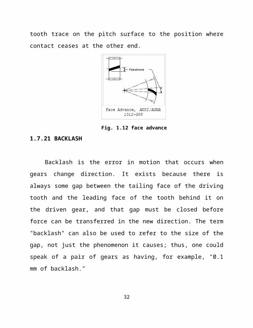
1.7.20 FACE ADVANCE
Face advance is the distance on a pitch circle through which a helical or
spiral tooth moves from the position at which contact begins at one end of the tooth
trace on the pitch surface to the position where contact ceases at the other end.
Fig. 1.12 face advance
1.7.21 BACKLASH
Backlash is the error in motion that occurs when gears change direction. It
exists because there is always some gap between the tailing face of the driving
tooth and the leading face of the tooth behind it on the driven gear, and that gap
must be closed before force can be transferred in the new direction. The term
"backlash" can also be used to refer to the size of the gap, not just the phenomenon
it causes; thus, one could speak of a pair of gears as having, for example, "0.1 mm
of backlash."
A pair of gears could be designed to have zero backlash, but this would
presuppose perfection in manufacturing, uniform thermal expansion characteristics
throughout the system, and no lubricant. Therefore, gear pairs are designed to have
some backlash. It is usually provided by reducing the tooth thickness of each gear
by half the desired gap distance.
23

In the case of a large gear and a small pinion, however, the backlash is
usually taken entirely off the gear and the pinion is given full sized teeth. Backlash
can also be provided by moving the gears farther apart. For situations, such as
instrumentation and control, where precision is important, backlash can be
minimized through one of several techniques. For instance, the gear can be split
along a plane perpendicular to the axis, one half fixed to the shaft in the usual
manner, the other half placed alongside it, free to rotate about the shaft, but with
springs between the two halves providing relative torque between them, so that one
achieves, in effect, a single gear with expanding teeth. Another method involves
tapering the teeth in the axial direction and providing for the gear to be slid in the
axial direction to take up slack.
1.7.22 UNDERCUT
Undercut is a condition in generated gear teeth when any part of the fillet
curve lies inside of a line drawn tangent to the working profile at its point of
juncture with the fillet. Undercut may be deliberately introduced to facilitate
finishing operations. With undercut the fillet curve intersects the working profile.
Without undercut the fillet curve and the working profile have a common tangent.
Fig. 1.13 Undercut
24

1.7.23 MODIFIED ADDENDUM TEETH
Teeth of engaging gears, one or both of which have non-standard addendum.
1.7.24 FULL-DEPTH TEETH
Full-depth teeth are those in which the working depth equals 2.000 divided
by the normal diametral pitch.
1.7.25 STUB TEETH
Stub teeth are those in which the working depth is less than 2.000 divided by
the normal diametral pitch.
1.7.26 EQUAL ADDENDUM TEETH
Equal addendum teeth are those in which two engaging gears have equal
addendums.
1.7.27 LONG AND SHORT-ADDENDUM TEETH
Long and short addendum teeth are those in which the addendums of two
engaging gears are unequal.
Fig. 1.14 long and short-addendum teeth25

1.8 AGMA- AMERICAN GEAR MANUFACTURERS ASSOCIATION
AGMA is a full service trade association representing 400 manufacturers
and users of gears and gearing products, suppliers of equipment and services to the
industry, individual consultants and academicians. AGMA has members in 30
countries and, in fact, is quickly becoming the Association for global
manufacturers in the gear industry.
1.8.1 AGMA QUALITY CLASS NUMBERS
The AGMA gear quality numbers range from 3 through to 15 and identify
the accuracy level of the tooth element tolerances that are permissible in the
manufacture of each particular gear in terms of its specialised use. The permissible
tolerances for the different quality numbers may be obtained from the AGMA
standards, which show the type of gear and the permissible tolerances and
inspection dimensions.
Application for AEROSPACE Quality Number
Actuators 7 - 11
Control Gearing 10 - 12
Engine Accessories 10 - 13
Engine Power 10 - 13
Engine Starting 10 - 13
Loading Hoist 7 - 11
Propellor Feathering 10 - 13
Small Engines 12 - 13
26

Once a suitable quality number has been decided, the relevant tolerances for
the tooth elements can be selected from the AGMA quality standards.
1.8.2 GEAR MATERIALS
The gear materials are classified as follows:
Heat resisting steels
Heat resisting alloys
Nickel based alloys
Special alloys:
1. Alacrite (cobalt based alloys)
2. Adnick (Nickel based alloys)
The various materials used for aero- engine gear manufacture are chromic
steel, carburized steel SAE1018, 1054, 4026, 4118,
4340, 4320, 4820 and 9310), Nitriding steel and Carburizing steel.
1.8.3 CHARACTERISTICS OF GEAR MATERIALS
It should resist inter crystalline corrosion.
It should work above 7500C.
It should have high temperature characteristics.
Resistance to hot turbine gases.
Saline corrosion resistance.
It should withstand oxidation upto 11000 C.
Good mechanical properties at elevated temperature.
27

28

1.9 GEAR CELL OF MACHINE SHOP MACHINES
1. Reishauer Gear Grinder: Used for grinding external profile of gear tooth.
2. Voumard Internal Grinder: Used for internal grinding of the gear.
3. Barber Colman Gear Hobber: Used for formation of gears teeth by hobbing
process.
4. Maxicut Gear Shaper: Used for formation of gear teeth by reciprocating
shaping process.
5. Gratomat: Used to provide contour break on the gear teeth by grinding
wheel.
6. Rotomat: Used for final finishing of gear by spindle deburring using
abrasives.
7. Lap Master: Used for lapping, this gives more accuracy than grinding.
8. Herbert 7: Is a lathe which is used for turning, facing etc.
9. Bevel Gear Cutting: Used for cutting bevel gears by shaping.
10.Samputensili Gear Hobber CNC: It’s a CNC used for hobbing process.
29
11.Fellows Gear Shaper CNC: It’s a CNC used for shaping process.
12.Okuma and Howa CNC lathe: It’s a CNC lathe used for operations like
turning, facing etc.
13.Hofler Gear Tester: Used to inspect the profile of the gear teeth.
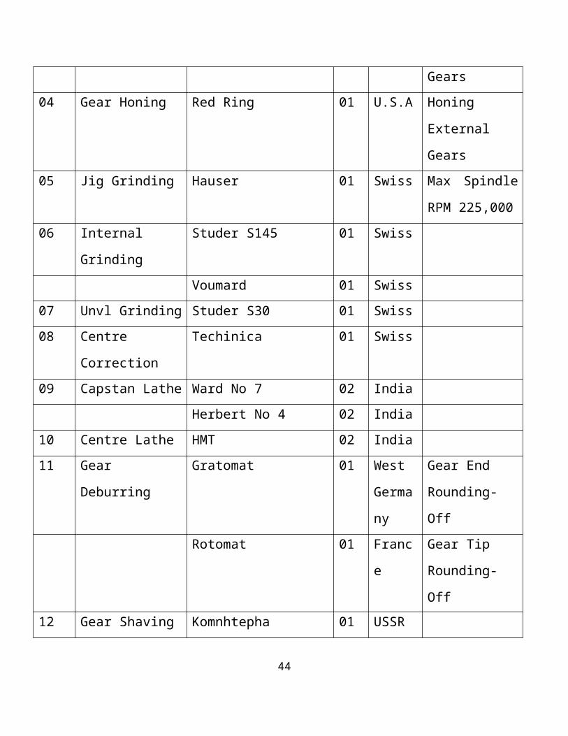
1.9.1FACILITY MATRIX- MANUFACTURE GEARS AT GEARS CELL
Sl.No Machine Type Make Qty Country Remarks
01 Gear Hobbing Barber & Coleman 01 U.S.A Ext Spur/Helical
Gears & Splines
Dowding & Doll 01 U.K Ext Small
Spur/Helical
Gears & Splines
Samputensilli 01 German
y
Ext Spur/Helical
Gears & Splines
Sykes 01 U.K Crown Hobbing
02 Gear Shaping Fellows-conventional 01 U.K Spur/Helical
Gears & Splines
Int & Ext
Fellows-cnc 01 U.K Spur/Helical
Gears & Splines
Int & Ext
Maxicutt 01 U.K Spur/Helical
30

Gears & Splines
Int & Ext
Sykes 01 U.K Spur/Helical
Gears & Splines
Int,Ext&Tapered
03 Gear Grinding Reishauer NZA 01 Swiss Spur & Helical
crowned Gears
CNC Reishauer RZS 01 Swiss Spur & Helical
crowned Gears
04 Gear Honing Red Ring 01 U.S.A Honing External
Gears
05 Jig Grinding Hauser 01 Swiss Max Spindle
RPM 225,000
06 Internal Grinding Studer S145 01 Swiss
Voumard 01 Swiss
07 Unvl Grinding Studer S30 01 Swiss
08 Centre Correction Techinica 01 Swiss
09 Capstan Lathe Ward No 7 02 India
Herbert No 4 02 India
10 Centre Lathe HMT 02 India
11 Gear Deburring Gratomat 01 West
German
y
Gear End
Rounding-Off
Rotomat 01 France Gear Tip
Rounding-Off
12 Gear Shaving Komnhtepha 01 USSR
31
1.9.2 GENERAL FLOW CHART- MANUFACTURE GEARS AT GEAR
CELL
RAW MATERIALS(Forging/casting/bar)
↓
BASIC HEAT TREATMENT TOBRING MACHINABILITY(Normalizing & tempering)
↓
GEAR BLANK PREPARATION(Lathe section)
↓
DATUM ESTABLISHMENT(Skim grinding)
↓
GEAR CUTTING(shaping, hobbing, broaching)
↓
BURR REMOVAL↓
CASE HARDENING(carburising, cynaiding, nitriding)
↓
SUPPORTING GRINDING OPERATIONS↓
PROFILE GRINDING↓
TEMPER ETCHING↓
FINAL GRINDING OPERATION (if any)↓
FINAL FINISHED COMPONENT
32

1.9.3 BASIC MACHINING OPERATIONS
Facing: An operation performed on lathe that feeds a single point tool
perpendicular to the axis of rotation of work to create a flat surface.
Turning: A machining operation used to make cylindrical or cone shaped
parts. A single point cutting tool passes along the outer surface of a
cylindrical work piece as it rotates and gradually removes a layer of
material.
Drilling: The process of using a multi- point tool to penetrate the surface of
the work piece and make a round hole
Boring: A process of enlarging and truing a pre- existing hole.
Reaming: The process of finishing and sizing the hole which has been
previously drilled or bored
Lapping: It is an operation of sizing and finishing of holes or turned
surfaces.
Chamfering: An operation performed on lathe that feeds tool to create a
beveled edge on the work piece.
Grooving: The process of reducing the diameter of a work piece over a very
narrow surface.
Milling: It is an operation of removing metal by feeding the work against
the rotating cutter having multiple cutting edges
Grinding: It is the operation of removing metal in the form of minute chips
by feeding the work against a rotating abrasive wheel.
Broaching: It is a method of removing metal by pushing or pulling a cutting
tool called broach which cuts in a fixed path.
33

CHAPTER 2
LITERATURE REVIEW
2.0 TURBO JET ENGINE
The turbojet is the oldest kind of general-purpose air breathing jet engine.
Two engineers, Hans von Ohain in Germany and Frank Whittlein the United
Kingdom, developed the concept independently into practical engines during the
late 1930s.
Turbojets consist of an air inlet, an air compressor, a combustion chamber, a
gas turbine (that drives the air compressor) and a nozzle. The air is compressed
into the chamber, heated and expanded by the fuel combustion and then allowed to
expand out through the turbine into the nozzle where it is accelerated to high speed
to provide propulsion.
Turbojets are quite inefficient if flown below about Mach 2 and very noisy.
Most modern aircraft use turbofans instead for economic reasons. Turbojets are
still very common in medium range cruise missiles, due to their high exhaust
speed, low frontal area and relative simplicity.
2.1 HISTORY
The first patent for using a gas turbine to power an aircraft was filed in 1921
by Frenchman Maxime Guillaume. His engine was to be an axial-flow turbojet, but
was never constructed, as it would have required considerable advances over the
state of the art in compressors.
Practical axial compressors were made possible by ideas from A.A.Griffith
in a seminal paper in 1926 ("An Aerodynamic Theory of Turbine Design").
On 27 August 1939 the Heinkel He 178 became the world's first aircraft to fly
under turbojet power with test-pilot Erich Warsitz at the controls, thus becoming
the first practical jet plane. The first two operational turbojet aircraft, the
34

Messerschmitt Me 262 and then the Gloster Meteor entered service towards the
end of World War II in 1944. A turbojet engine is used primarily to propel aircraft,
but has been used for other vehicles, such as cars. Air is drawn into the rotating
compressor via the intake and is compressed to a higher pressure before entering
the combustion chamber. Fuel is mixed with the compressed air and ignited by a
flame in the eddy of a flame holder. This combustion process significantly raises
the temperature of the gas.
Hot combustion products leaving the combustor expand through the turbine
where power is extracted to drive the compressor. Although this expansion process
reduces the turbine exit gas temperature and pressure, both parameters are usually
still well above ambient conditions. The gas stream exiting the turbine expands to
ambient pressure via the propelling nozzle, producing a high velocity jet in the
exhaust plume. If the momentum of the exhaust stream exceeds the momentum of
the intake stream, the impulse is positive, thus, there is a net forward thrust upon
the airframe.
Early generation jet engines were pure turbojets, designed initially to use a
centrifugal compressor (as in the Heinkel HeS 3), and very shortly afterwards
began to use Axial compressors (as in the Junkers Jumo 004) for a smaller
diameter to the overall engine housing. They were used because they were able to
achieve very high altitudes and speeds, much higher than propeller engines,
because of a better compression ratio and because of their high exhaust speed.
However, they were not very fuel efficient. Modern jet engines are mainly
turbofans, where a proportion of the air entering the intake bypasses the
combustor; this proportion depends on the engine's bypass ratio. This makes
turbofans much more efficient than turbojets at high subsonic/transonic and low
supersonic speeds.
35

One of the most recent uses of turbojet engines was the Olympus 593 on
Concorde. Concorde used turbojet engines because it turns out that the small cross-
section and high exhaust speed is ideal for operation at Mach 2. Concorde's engine
burnt less fuel to produce a given thrust for a mile at Mach 2.0 than a modern high-
bypass turbofan such as General Electric CF6 at its Mach 0.86 optimum speed.
Concorde's airframe, however, was far less efficient than that of any subsonic
airliner.
Turbojet engines had a significant impact on commercial aviation. Aside
from being faster than piston engines, turbojets had greater reliability, with some
models demonstrating dispatch reliability rating in excess of 99.9%. Pre-jet
commercial aircraft were designed with as many as 4 engines in part because of
concerns over in- flight failures. Overseas flight paths were plotted to keep planes
within an hour of a landing field, lengthening flights. Turbojets' reliability allowed
for three and two-engine designs, and more direct long-distance flights. Although
ramjet engines are simpler in design as they have virtually no moving parts, they
are incapable of operating at low flight speeds.
2.2 EARLY DESIGNS
Early German engines had serious problems controlling the turbine inlet
temperature. A lack of suitable alloys due to war shortages meant the turbine rotor
and stator blades would sometimes disintegrate on first operation and never lasted
long. Their early engines averaged 10–25 hours of operation before failing, often
with chunks of metal flying out the back of the engine when the turbine
overheated. British engines such as the Rolls-Royce Welland tended to fare better,
being type certificated for initially 80 hours, later extended to 150 hours between
overhauls, as a result of an extended 500 hour run being achieved in tests.
36

Fig 2.1 J85-GE-17A turbojet engine from General Electric (1970)
The United States had the best materials because of their reliance on
turbo/supercharging in high altitude bombers of World War II. For a time some US
jet engines included the ability to inject water into the engine to cool the
compressed flow before combustion, usually during takeoff. The water would tend
to prevent complete combustion and as a result the engine ran cooler again, but the
planes would take off leaving a huge plume of smoke.
Today these problems are much better handled, but temperature still limits
turbojet airspeeds in supersonic flight. At the very highest speeds, the compression
of the intake air raises the temperatures throughout the engine to the point that the
turbine blades would melt, forcing a reduction in fuel flow to lower temperatures,
but giving a reduced thrust and thus limiting the top speed. Ramjets and scramjets
do not have turbine blades; therefore they are able to fly faster, and rocket engines
run even hotter still.
37
At lower speeds, better materials have increased the critical temperature, and
automatic fuel management controls have made it nearly impossible to overheat
the engine.
2.3 EXOSKELETAL ENGINE
The exoskeletal engine (ESE) is a concept in turbomachinery design.
Current gas turbine engines have central rotating shafts and discs and are
constructed mostly from heavy metals. They require lubricated bearings and need
extensive cooling for hot components. They are also subject to severe imbalance
(or vibrations) that could wipe out the whole rotor stage, are prone to high- and
low-cycle fatigue, and subject to catastrophic failure due to disc bursts from high
tensile loads, consequently requiring heavy containment devices. To address these
limitations, the ESE concept turns the conventional configuration inside-out and
utilizes a drum-type rotor design for the turbo machinery in which the rotor blades
are attached to the inside of a rotating drum instead of radially outwards from a
shaft and discs. Multiple drum rotors could be used in a multi-spool design.
Fundamentally, the ESE drum-rotor configuration typically consists of four
concentric open-ended drums or shells:
an outer shell (engine casing) that both supports the bearings for the drum-
rotor shell and constrains it,
the drum-rotor shell that rotates within the bearings and carries the
compressor- and turbine blades,
a static stator shell that supports the guide vanes,
a hollow static inner shell that provides a flow path through the centre of the
engine.
38

In the ESE design, the rotating blades are primarily in radial compression as
opposed to radial tension, which means that materials that do not possess high-
tensile strength, such as ceramic materials, can be used for their construction.
Ceramics behave well in compressive loading situations where brittle fracture is
minimized, and would provide greater operating efficiency through higher
operating temperatures and lighter engine weight when compared to the metal
alloys that typically are used in turbomachinery components. The ESE design and
the use of composite materials could also reduce the part count, reduce or eliminate
cooling, and result in increased component life. The use of ceramics would also be
a beneficial feature for hypersonic propulsion systems, where high stagnation
temperatures can exceed the limits of traditional turbomachinery materials.
The cavity within the inner shell could be exploited in several different
ways. In subsonic applications, venting the centre cavity with a free-stream flow
could potentially contribute to a large noise reduction; while in supersonic-
hypersonic applications it might be used to house a ramjet or scramjet (or other
devices such as a pulse-detonation engine) as part of a turbine-based combined-
cycle engine. Such an arrangement could reduce the overall length of the
propulsion system and thereby reduce weight and drag significantly
39
CHAPTER 3
MECHANICAL OPERATIONS
3.0 GEAR CUTTING
3.1 PRE- CUTTING OPERATIONS
3.1.1 GEAR BLANK MANUFACTURE:
Aero engine blanks are prepared by Drop Forging process. Internal stresses
created are relieved by heat treatment. Basic heat treatment is done to increase the
hardness value to RC 28-38 so that the gear blank is machinable.
3.1.2 LATHE OPERATIONS:
Subsequent operations like step turning, grooving, boring etc. are done on
lathe. Tolerance range is within 5 mm.
3.1.3 OD AND ID GRINDING:
Outer diameters are ground in an external grinding machine. Ex. Studer
Universal Grinder. Internal Diameters or bore grinding is done on an internal
grinding machine. Ex. Voumard Internal Grinder.
3.1.4 SELF-CENTERING:
As the manufacturing is done, the centre line of the gear blank is the same as
the centre line of a gear. Reference surface on the gear blank ends is marked by the
self-centering machine, facilitating easy location of the job on the gear cutting
machines.
40

3.2 GEAR HOBBING
Fig. 3.1 gear hobbing
This is a gear generating process and not gear cutting process. Gear hobbing
is a continuous indexing process in which the hob and the gear rotate in a timed
relationship with one another while the hob is fed into the work. The teeth are cut
at one pass of the hob. This method is employed to manufacture aero engine gears
extensively because of the high profile accuracy that can be achieved by it. Gears
can also be manufactured on a large scale by this method.
3.3 GEAR SHAPING
This is a gear generating process where a pinion type tool is used. The tool
called shaper cutter is made of a material of higher strength than the material to be
cut. The tool rotates and reciprocates in a timed fashion with a gear blank which is
stationary. The cutting action takes place when the tool moves down. During the 41

return stroke, to prevent the dragging of the tool with the work, the work table is
slightly reciprocated in horizontal direction away from the tool. Then it comes
back to the initial position at the beginning of the next cut.
3.4 GEAR MILLING
Gear milling is a gear cutting operation where the gear tooth space is cut by
a form milling cutter. After each tooth space is milled the gear blank is indexed to
the next position for milling. This process is repeated and the entire gear is made.
3.5 GEAR BROACHING
Broaching can be defined as a machining process that removes metal from a
part by pulling or pushing a multiple tooth tool called a broach through or along
the surface of the work. Broaching is actually used in mass production since it
involves less machining time and labour.
3.6 SHEAR SPEED CUTTING
Used for cutting large size gears. A separate tool is used to cut each tooth
space. Non symmetrical gears can be cut by assembling different tools around the
gear blank in the cutting tool holder. The tools can be fed radially to achieve the
full depth of cut and retracted at the return stroke to prevent dragging of tool with
the work. The tool is stationary while the work is reciprocated past the tool in a
straight line.
42

3.7 BEVEL GEAR CUTTING
In bevel gear straight tooth generating machine the tools take the place of the
mating gear and their paths are lines converging on the pitch cone apex. The action
of the machine causes the work piece mounted on the spindle to roll as if it were in
contact with its mating gear.
3.8 GEAR FINISHING
Gear finishing operations are used for improving accuracy and/ or
uniformity of various gear tooth elements. It is necessary to control errors
(eccentricity, pitch, and profile and helix angle) for quietness and maximum
service life. In aero engine gear manufacture the finishing operations is the most
expensive operation.
3.9GEAR SHAVING
Gear shaving is a gear finishing operation which removes small amounts of
metal from the working surfaces of the gear teeth. Its purpose is to correct errors in
index, helix angle, tooth profile and eccentricity. The process can also improve
tooth surface finish, and eliminate by crowned tooth forms, the danger of tooth and
load concentrations in service.
Shaving provides form modifications that reduce gear noise, increase load
carrying capacity, and its service life. The rotary gear shaving process uses a
gashed rotary cutter in the form of a helical gear having helix angle different from
the gear that have to be shaved. The wheel is then passed through the space while
grinding occurs on the two adjacent teeth flanks and the root.
43
3.10 GEAR HONING
Gear honing is a gear finishing process that was developed to improve the
sound characteristics of hardened gears by removing nicks and burrs, improving
surface finish, making minor correction in tooth irregularities caused by heat treat
distortion. This can add significant wear life and sound qualities of both shaved
and ground hardened gears.
3.11GEAR GRINDING
Grinding is a technique of finish-machining, using an abrasive wheel. The two
most common techniques in gear grinding are
Generating Grinding: Here the threaded grinding wheel replaces the gear
hobber in gear hobbing technique. The ratio of work speed and wheel speed
when grinding spur gears is a simple ratio of teeth on the gear and number of
starts on the wheel.
Saucer Wheel Method: In this technique, two saucer shaped wheels are used.
The grinding surfaces of the two wheels represent the rack, and the involute
profile is generated by gear rolling relative to and in contact with the two
grinding wheels.
Form Grinding: In this technique the abrasive grinding wheel is profiled to
represent the space between two adjacent teeth on a gear. The wheel is then
passed through the space while grinding occurs on the two adjacent teeth
flanks and the root.
44

3.12 GEAR LAPPING
Lapping is a method of refining gear elements by removing small errors of
distortion resulting from heat treatment operations. Lapping tool is usually made of
a soft material that will readily carry the abrasive used to do the cutting while the
work gear and lapping gear are running together.
3.13 GEAR DEBURRING
A burr is a plastically deformed material at an edge generated by a chip
producing process. The process of removing burrs is called deburring operation
which is achieved by chamfering the edges of the gear. Deburring reduces gear
noise and stress concentration effects. Gratomat is one of the machines used for
deburring.
3.14 FORM GRINDING
In this technique the abrasive grinding wheel is profiled to represent the
space between two adjacent teeth on a gear. The wheel is then passed through the
space while grinding occurs on the two adjacent teeth flanks and the root.
The reason for heating and holding the steel in the Austenite is to dissolve
Carbide cementites into a matrix. Because of the rapid cooling, there is no time for
Austenite decomposition. At this stage, the trapped carbon causes a shift in the
atom which creates a stressed lattice structure. This stressed lattice structure, called
Martensite, is hard and brittle. The tool rotates and reciprocates in a timed fashion
with a gear blank which is stationary. The cutting action takes place when the tool
moves down. During the return stroke, to prevent the dragging of the tool with the
work, the work table is slightly reciprocated in horizontal direction away from the
tool. Then it comes back to the initial position at the beginning of the next cut.
45

3.15 HEAT TREATMENT
Heat treatment is the controlled heating and cooling of materials in order to
deliberately alter their mechanical properties. All heat treatment processes involve
3 main parts:
Heating the metal to the pre-determined heat treating temperature.
The soaking of the metal at that temperature until the structure becomes
uniform throughout the section.
The cooling of the metal at some pre-determined rate such will cause the
formation of, or will maintain desirable structures within the metal.
The hardness and depth of the case obtained is low in the annealed and
normalized steels with a Ferrite-Pearlite structure than for hardened and tempered
steels with a Sorbite structure. Hence basic hardening and tempering is adopted for
basic heat treatment of gears.
3.15.1 BASIC HEAT TREATMENT
3.15.1.1 NORMALIZING
Objectives:
i. To refine grain size.
ii. To improve machinability of low carbon steel.
iii. To increase strength of medium carbon steel.
iv. To achieve certain mechanical and electrical properties.
v. To relieve internal stresses.
vi. To refine the crystalline structure after steel has been coursed by previous
hot working. Eg: Welding, bending etc.
vii. To obtain more uniform structure for easy machining.
46

This process quite similar to annealing, but this is carried out by slow heating
the steel to above the critical temperature ( 850ºc -950ºc ) and then allowing to cool
freely in still air i.e; slow cooling. All forgings and castings undergo this treatment
before initial machining.
3.15.1.2 HARDENING
This treatment consists of heating the steel to a selected hardening
temperature, and holding it at this temperature for sufficient period to complete
transformation to Austenite (generally 1 hour per 25 mm of section thickness),
followed by cooling or quenching at a rate fast enough to develop the desired
hardness. The reason for heating and holding the steel in the Austenite is to
dissolve Carbide cementites into a matrix. Because of the rapid cooling, there is no
time for Austenite decomposition. At this stage, the trapped carbon causes a shift
in the atom which creates a stressed lattice structure. This stressed lattice structure,
called Martensite, is hard and brittle.
3.15.1.3 TEMPERING
The rapid cooling during hardening induces internal stresses in steels leading
to cracking and warping. This difficulty can be overcome by relieving the stress by
process called tempering. Thus hardening is always followed by tempering. The
process consists of:
Re-heating the quenched steel to a temperature below 7230C
Holding it for a fixed time period.
Slow cooling in air to room temperature.
47

3.15.1.4CASE HARDENING
Aero- engine gears are subjected to both wear and repeated shocks. Hence,
steel must be hard enough to withstand wear, tough enough not to be readily
fractured by shock, and low enough in first cost to be economical. Hence these
parts are subjected to case hardening processes such as Nitriding, Carburizing and
Cyaniding.
3.15.1.5 NITRIDING
Nitriding is a process of case-hardening in which steel is heated in an
atmosphere of NH3 gas at a temperature of 490-5500C, for a prolonged period
depending upon the case depth required. At this temperature range, ammonia gas
dissociates to produce atomic(nascent) nitrogen.
The atomic nitrogen diffuses into the steel forming nitrides, thus producing a
hard wear resisting surface free from scale containing, the minimum of distortion.
Only low alloy steels containing chromium, aluminum, molybdenum, vanadium,
tungsten etc. can be nitrided. Plane carbon steels are not suitable for nitriding.
3.15.1.6 CARBURISING
Carburising is a heat treatment process which increases the surface carbon
content of low carbon steel by 0.7- 1.0% in carbon medium. In practice,
carburizing is done at temperatures between 900- 9500C. During carburizing, three
important changes take place.
First, the atomic carbon liberated from the carbonaceous medium. Secondly,
the carbon atom from the carburizing is transferred to the surface of the steel.
Thirdly, the carbon so absorbed by the surface of the steel is diffused deep into it.
48

The components after carburizing, are usually directly quenched or cooled,
re-heated, and quenched in oil or in warm bath, depending on the alloy content to
get the Martensitic structure.
3.15.1.7 CYANIDING
Cyaniding also called liquid carbo- nitriding, is used to impart carbon and
nitrogen to the surface of the components especially on small parts. The
component is pre-heated to 200- 5000C to remove the moisture and then immersed
in the bath by using some suitable fixture. The charge is then heated until the
required temperature of 850- 9000C is got.
The charge is then allowed to soak for about 10- 60 minutes, depending on
the required case depth. Then the components are quenched in oil or water. This
process is generally applicable to low carbon and low alloy steels, nickel,
nickel/chromium steels.
3.15.1.8 STRESS RELIEVING
Stress relieving is a heat treatment designed to relieve the stress induced in
the component, minimize the distortion during subsequent heat treatment
(nitriding, carburizing etc.) and to avoid the formation of cracks in extreme cases.
Stress relieving is done by heating the steel to a temperature of 550-7000C, and
soaking it for at least 2-4 hours thoroughly to achieve uniformity throughout the
component. Then it is cooled to ambient temperature in a furnace.
49

At temperatures above 500-6000C, steel almost entirely ceases to be elastic,
and becomes ductile. For this reason, the internal stresses developed in the steel at
such temperatures are gradually relieved as a result of local plastic deformations
caused by them.
3.15.1.9 DEEP FREEZING
The deep freeze is another process that can improve hardness and wear and
achieve the proper microstructure. Through the use of the liquid nitrogen system,
sub- zero temperatures as low as -320oF are accurately controlled to completely
transform austenite into martensite.
50

CHAPTER 4
DESIGN
4.1 TURBO- JET ENGINE
Gas turbine engine in which a nozzle is used to obtain thrust by expanding
exhaust gases coming out of Turbine to ambient pressure is known as turbo-jet
engine. It has revolutionized air travel, reducing expense, increasing aircraft safety,
increasing cruise velocities, lengthening ranges, increasing payloads and lowering
maintenance. It has, however, a large fuel consumption rate, more so with after-
burning capability.
The greatest thrust would be obtained if the nozzle expands the gases to the
atmospheric pressure. The thrust delivered by a turbojet decreases as the
surrounding air temperature increases because the decreased density of the hot air
reduces the mass flow through the engine.
fig 4.1 turbo- jet engine
51

• The requirement of this engine to meet a Specific Aircraft Application has
been “Light Weight, Low Cost, Short Life” Turbojet Engine of 380 kg
Thrust with a Maximum Envelope Diameter of 330 mm and Dry Engine
Weight of 72 kg.
• The Engine shall be suitable for operation from a Remote Ground Station
through Tele command. The Engine should have life of approximately 6
hours or 30 Starts or 5 Sea Recoveries whichever occurs early.
4.2 GENERAL DESCRIPTION
4.2.1 ENGINE
This description considers the main functional components of the engine.
The single shaft straight flow turbojet engine consists of:
o A four stage axial flow compressor, rotors and stators with integral blades.
o A straight flow annular combustion chamber.
o A single stage axial turbine with integral blades and an un-cooled nozzle
guide vane.
o A fuel manifold.
o Exhaust cone with integral fixed area propelling nozzle.
o High speed direct driven permanent magnet alternator and fuel pump.
o Use of high capacity fuel cooled switch mode power supply for regulated
28V.
o DC power up to 1.1 kW.
o Elimination of gear drives by using total loss mist lubrication.
52

4.2.2 CONSTRUCTION AND PRINCIPLE OF OPERATION
The direct engine driven brushless alternator of the PGU has stator with
three phase star winding and a rotor with 8 numbers of sintered Samarium Cobalt
permanent magnets. The remanence of the magnets shall be 980 mT (minimum)
and the energy density shall be 180 kJ/m3 (minimum).
The stator is housed in aluminium casing. The rotor is supported on a pair of
grease packed bearings. The alternator generates 3 phase, sinusoidal voltage whose
amplitude and frequency varies with the speed of rotation of the alternator. The
alternator is placed in the nose bullet and mounted directly to the engine. The rotor
is connected to the engine shaft by means of the quill shaft.
The rectifier assembly consists of MIL qualified three phase bridge rectifiers
with electrically insulated heat sink case (JANTX 483- 03 or JANTX 483- 02).The
bridges are mounted on both sides of an aluminium pipe, through which aircraft
fuel can be passed to the engine's fuel pump inlet. A three phase diode bridge
assembly rectifies the three phase AC voltage generated by the alternator to
provide an unregulated DC voltage of 0– 60 Volts.
This ATF-Jet A1 fuel facilitates the necessary cooling for the bridge
rectifier. The rectifier assembly is fixed in the annular space around the alternator
in the nose bullet. The alternator wiring harness is routed to the outside of the
engine and interfaced to the main vehicle through connector.
4.2.3 AIR INTAKE SECTION
This section consists of an Air Intake Casing (AIC) which carries the front
rotor bearing. The alternator and the fuel pump are mounted on the front of the
AIC in that order.
53

A quill shaft connects the alternator rotor to the front of the compressor-
turbine shaft (CT shaft) tie rod and another quill shaft connects fuel pump drive
gear to the alternator rotor. The fuel cooled bridge rectifier is mounted on the
alternator housing. The DECU is mounted in the front of the fuel pump.
fig. 4.2 air intake section
4.2.4 COMPRESSOR SECTION
The Compressor section comprises four stages of axial compressor, each
stage having a rotor and a stator. All the rotors and stators are made of aluminium
alloy and are having integral blades. Labyrinth seals between successive rotors
minimise inter-stage air leakage.
A thrust balancing disc is present at the rear of the fourth stage compressor
which uses the difference in the compressor outlet pressure and the ambient
pressure to minimise end thrust on the engine ball bearing. The stator rings are
bolted together at the flanges.
54

fig 4.3 compressor section
4.2.5 DIFFUSER CASING
Casing is bolted to the Compressor stator ring stage 3. The inner and outer
casings are joined by 4 radial struts. Stator Ring Stage 4 is bolted at the front of the
diffuser casing.
At the rear, the casing has a flange for the combustion chamber outer casing.
The engine front mounting and the air start adaptor are positioned on the diffuser
casing rear flange.
fig 4.4 diffuser casing
55

4.2.6 COMBUSTION SECTION
Combustion Section consists of an annular combustion chamber, an external
casing, fuel manifold with 16 fuel nozzles and an Igniter plug. The combustion
chamber outer casing (CCOC) houses the flame tube assembly and provides bosses
for fixing the igniter plug, air impingement tubes, fuel manifold and air tapping for
mist generation and A/C fuel tank pressurization.
fig 4.5 combustion section
4.2.7 TURBINE SECTION
This comprises a single stage axial turbine rotor with integral blades and a
nozzle guide vane assembly. The turbine rotor is an integrally cast rotor blade and
disc unit. The front of the turbine rotor is bolted to the CT shaft and the rear is
supported by a roller bearing in the exhaust cone assembly.
56

Fig. 4.6 turbine section
4.2.8 ROTOR ASSEMBLY
The compressor rotors, the thrust balancing disc, a front shaft, compressor
turbine shaft (CT shaft) and the tie rod along with the turbine rotor form the main
rotating assembly. Curvic couplings are present on the ends of the compressor
turbine shaft (CT shaft), the rear end of front shaft and the front end of the turbine
rotor.
4.2.9 EXHAUST SECTION
The exhaust cone is secured to the rear of the combustion chamber outer
casing. The inner cone and the outer cone are joined by three radial hollow struts.
The inner cone accommodates the rear bearing housing.
57

fig. 4.7 exhaust section
4.3 SPECIFICATION
CONDITION : ISA – SEA LEVEL – STATIC
THRUST : 380 kgf (373 daN)
SFC : 1.18 kg/kgf-h
AIR MASS FLOW : 6.65 kg/s
COMPRESSOR
PRESSURE RATIO : 4.6
TET : 1200 K
ENGINE SPEED : 29,500 rpm
COMPRESSOR : 4 STAGE AXIAL
TURBINE : 1 STAGE AXIAL
COMBUSTOR : ANNULAR
OVERALL LENGTH : 1400 mm
MAXIMUM DIAMETER : 330 mm
WEIGHT : 72 kg58

4.4 MAJOR COMPONENTS OF THE ENGINE
Airintake casing
4 Stage Compressor to achieve Pressure Ratio of 4.65 and Integrally Bladed
Compressor Rotors and Stators in Aluminium Alloy.
Short Annular Combustor.
Integrally Bladed Precision Investment Casting for Turbine Stator and Rotor
in Super alloy to Meet Uncooled Turbine Operation upto 1200K.
High Speed (29,500 rpm) Rotor on Flexible Bearing Supports.
4.5TECHNOLOGICAL HIGHLIGHTS
Successful Flight of the Totally Indigenously Designed Aero Jet Engine
marks an Important Milestone in the History of Indian Aviation.
The Engine incorporates a microprocessor controlled closed loop hydro-
mechanical Fuel System.
The unit delivers fuel scheduled through an electronically controlled
metering system in response to the speed demand.
The engine control system consists of the Digital Electronic Control Unit
(DECU), Fuel Metering Unit and the Fuel Pump.
4.6 ABOUT QUILL SHAFT
59

4.6.1 CONSTRUCTIONAL DETAILS
Air Intake section consists of an Air Intake Casing (AIC) which carries the
front rotor bearing. The alternator and the fuel pump are mounted on the front of
the AIC in that order. A quill shaft connects the alternator rotor to the front of the
compressor-turbine shaft (CT shaft) tie rod and another quill shaft connects fuel
pump drive gear to the alternator rotor.
4.6.2 DESIGN CONDITION
Torque required to rotate alternator rotor should withstand the quill shaft.
The quill shaft should be less stronger in order to save the engine.
Quill shaft should have proper splines so that it could mate properly with the
main shaft.
4.6.3 FUNCTION OF THE QUILL SHAFT
Main function of the quill shaft is to transfer the power from the Alternator
shaft to the Compressor– Turbine shaft (CT shaft).
It is also used for the safety of the engine when excessive load is produced.
4.6.4 DEFINITION OF THE PROBLEM
The quill shaft that is used in the Turbojet Engines has
1. Taper teeths i.e., un even addendum and deddendum
2. Tooth parallelism error is beyond drawing limit(0.0002”)
3. Chattering marks appeared on the splines due to which profile error goes
beyond the drawing limit (+0.0002”/-0.0004”, zero at pitch point)
4. Bending occurs during the various operations like lathe, grinding.
60

The manufacture of a quill shaft cannot be done in one process. It involves
variety of processes like turning, grinding gear cutting. etc. These processes are
determined based on the component drawing. These processes have to be carried in
a specific order.
4.6.5 SPECIFICATION OF QUILL SHAFT
4.6.5.1 MATERIAL SPECIFICATION
Material : Chromium Steel
Specification :AMS 5622
Heat Treatment : Heat Treatment at 5500C +/-50C for 4 hours and
cool in air
Non- Destructive Test : Magnetic Particle Inspection
4.6.6 PROCESS BEFORE MODIFICATION
PROCESS:-1
Machine Tool : INCINNATI C’less Grinder
Operational Description : Centerless Grind Dia
134
15.57
61

PROCESS:-2
Machine Tool:-HMT C’lathe
Operational Description:-Load To Soft Jaws And Machine As Per Sketch Process
PROCESS:-3
Machine Tool:-HMT C’lathe
Operational Description:-Load To Soft Jaws And Machine As Per Sketch Process
62

PROCESS:-4
Machine Tool:-HMT C’lathe
Operational Description:-Load Between Center Machine As Per Sketch
PROCESS:-5
Machine Tool:-HMT C’lathe
Operational Description:-Load Between Center Machine As Per Sketch
PROCESS:-6
63

Machine Tool:-Technical Center Correction Machine
Operational Description:- Center Corection Both Ends
PROCESS:-7
Machine Tool:-Studer Universal Grinder
Operational Description:-Load Between Center Grind Dia
64

PROCESS:-8
Machine Tool:-Studer Universal Grinder
Operational Description:-Load Between Center Grind Dia
PROCESS:-9
Machine Tool:-Dowding And Dool Hobber
Operational Description:-Load To Fixture Hob Splines
PROCESS:-1065

Machine Tool:-Dowding And Dool Hobber
Operational Description:-Load To Fixture Separtions
4.6.7 PROCESS AFTER MODIFICATION
PROCESS:-1
Operation description:-grind OD as shown
Machine tool:-CINCINNATI C’less grinder
PROCESS:-2
Machine tool:-Schaublin centre lathe
66

Operation Description:-Hold in soft jaws. Face end face and form centre as shown
PROCESS:-3
Machine tool:-Schaublin centre lathe
Operation Description:- Hold in soft jaw. Face end face and form centre as shown
PROCESS:-4
67

Machine tool:-Schaublin centre lathe
Operation Description:-Hold between centre.Machine as shown
PROCESS:-5
Machine tool:-Technical centre correction machine
Operation Description:- Correct centres as shown
PROCESS:-6
Machine tool:-Studer universal grinder
68

Operation Description:-Hold between centers, grind dia as shown.
INVOLUTE SPLINE DATA FOR 3/8”NOM.FILLET ROOT SIDE FIT
No of splines 17
Diametral Pitch 48/96
Pressure angle 300
Major dia 0.375”/0.372”
Minor dia 0.3125”/0.3050”
Form dia 0.3293”
Pitch dia 0.3542”
Base dia 0.3067”
Circular spline thick max eff 0.312”max act 0.0299” (ref)
min eff 0.03”(ref) min act 0.0287”
Involute profile error +0.0002”
(zero at pitch point) -0.0004”
Max pitch error 0.0013”
Measurement over pins 0.04081”/0.4098”
PROCESS:-7
Machine tool: Dowding and doll hobber
69

Operation Description:-Form splines as shown
PROCESS: 8
Machine tool:-Schaublin centre lathe
Operation Description:-Load between centre machine as shown
PROCESS: 9
Machine tool:-Technical centre correction machine
70

Operation Description:-centre correct as shown
PROCESS:10
Machine tool: Studer universal grinder
Operation Description: Hold between centre grinder outer dia as shown
PROCESS: 11
Machine tool: Dowding and dool hobber71

Operation Description: form splines as shown
EXTERNAL SERRATION DATA
No of teeth 15
Diametral pitch 80/160
Pressure angle 450
Pitch circle diameter 0.1875”
Nominal diameter 0.200”/0.198”
Minor diameter 0.173”/0.175”
Dimensions over pins 0.2246”/0.2236”
Measuring pin diameter 0.244”
Circular tooth thickness with gauge 0.0216”max eff
Tooth parallelism error across face
within
0.0004”max
Eccentricity of pitch dia. with axis of
centres
0.0015”fir max
PROCESS: 12
Machine tool:-Schaublin centre lathe
72

Operation Description:-Hold between centre machine as shown
4.6.7 THE REQUIRED QUILL SHAFT
CHAPTER 5
CONCLUSION
73

The modified design was studied and the inspections on all the surfaces
including splines were done. The modified designing of the quill shaft reduced the
errors in the gear profiles and proper meshing of splines is made for the successful
power trabsmission.
74

CHAPTER 6
BIBLIOGRAPHY
In the process of finding a solution we went through several books
and websites. These are mentioned below
BOOKS
Practical Gear Design by D.W.Dudley
Modern gear production by H.J.Watson
Gear Engineering by H.E.Merit Pitman publications
WEBSITES
www.firstgear.com
www.efunda.com
www.adamsmachinery.com
www.ansi.org
75