Modern High Voltage Drive Train Architecture to ... · Conference on Future Automotive Technology...
8
Conference on Future Automotive Technology Focus Electromobility München, March, 18-19 st 2013 Modern High Voltage Drive Train Architecture to Accommodate the Needs for a Variety of Components for Future Automotive Applications Conference on Future Automotive Technology: Focus Electromobility Karsten Mueller 1 and Rico Heinrich 2 1 Systems E-Traction Division, IAV GmbH, Gifhorn, Germany 2 Transmission, Hybrid and Electrification, IAV Inc., Northville 48167, USA E-mail: [email protected], [email protected] ABSTRACT: We can see a variety of different concepts in prototypes and series programs. In HEV drivetrains with power-split architecture, the use of a DC to DC boost converter between the high voltage battery and the voltage source inverter is widely spread for years. Though often discussed, a boost converter in a parallel hybrid (HEV) or pure electric vehicle (EV) drivetrain architecture has no break-through yet. By introducing a high voltage DC to DC converter to the (H)EV architecture, an additional degree of freedom is added to the system design. That can be used to develop new drivetrain concepts to improve efficiency of components, energy management strategy, system costs and add additional benefits for customers. The presentation will take a closer look at the effects and opportunities of a high voltage DC/DC converter for the overall drivetrain architecture. Keywords: electrical drive train, DC boost converter, DC buck converter, MTPA, optimal DC-link voltage, high voltage drivetrain 1. INTRODUCTION Currently we see an increasing number of different types of vehicles, which are already in production or just on tiheir way into dealer showrooms, equipped with components freshly developed to electrify our modern driving experience. One of the most sold and well known representative of its kind is the Toyota Prius in its third generation and a plug-in version since 2009. Forced by politics, customer expectations, increasing oil prices, environmental responsibilities and the attraction of cutting edge technologies all major automotive OEMs are developing high voltage drivetrain architectures and their Tier 1 suppliers are following suit. This expansion leads to a huge variety of different types of architectures like pure electric vehicles (pure EV), Plug-in Hybrids, parallel Hybrids, serial Hybrids, EV with range extender devices, power splits and axle splits and many more. These varied types are equipped with an even greater assortment of unique high voltage components like (see Figure 1): • Electrical Motors (EM) o Interior permanent magnet motors (IPMSM) o Induction motors (IM) o Switched reluctance motors (SRM) o Brushless DC motors (BLDC) • Energy storage systems (ESS) o Lithium-Ion battery o Nickel-metal-hydride battery o Fuel cell system o Super capacitors (Super-caps) o Lithium-air battery • Energy transfer and modulation devices o Voltage source inverter (VSI) o Low voltage DC to DC converter o High voltage DC to DC converter o AC to DC converter as charging devices o Inductive charging devices • Auxiliary devices o High voltage climate compressor o PTC heating One particular parameter drives the design for those components, listed above. The DC-link voltage is the key design parameter for all the different drivetrain architectures. The voltage level for the DC-link vehicle bus is commanded by the main source of electrical energy in the system (the high voltage battery, and for most systems). This dependency leads to severe limitations for the drivetrain architecture design, the component layout (especially the EM) as well as the energy management and control strategy. Figure 1: x-EV architectures To overcome this limitation, a high voltage DC to DC converter could be used to decouple the ESS voltage level from the vehicle DC-bus voltage level and gain an extra degree of freedom to be leverage for system design, control and energy management. A well-known example for such a kind of separation between ESS voltage level and vehicle DC-bus in certain drive situation is the Toyota Prius since its second generation. As described in [1] and [2], the changes resulted in system improvements for design, control and energy management. This paper gives a more detailed insight of the effects of a high voltage DC to DC converter induced to pure electric vehicle architecture. It outlines different opportunities for the overall system design, which the automotive industry is presently facing. Aspects of potential energy savings, reduction of components variety and an increasing fulfilment of customer expectations are discussed. As summarized in this paper, there is a path outlined for future drivetrain architecture and set of components to reduce costs, increase efficiency and increase performance and customer expectations satisfaction. 2. SYSTEM ARCHITECTURE WITH HIGH VOLTAGE DC TO DC CONVERTER 2.1. Current DC-link bus design When we look at the current DC-link bus design in common electrical drive trains, we see the situation outlined in Figure 2. We see a varying Lithium-Ion battery voltage, which is varying by the current State of Charge (SoC) and the current battery current I Bat . Typical values for the lowest and highest allowed cell voltage are shown in Figure 2. At a cell voltage of 3.2 V the cell is considered as “fully” discharged and at a cell voltage of 4.2 V as “fully” charged.
Transcript of Modern High Voltage Drive Train Architecture to ... · Conference on Future Automotive Technology...
Conference on Future Automotive Technology
Focus Electromobility
München, March, 18-19st 2013
Modern High Voltage Drive Train Architecture to Accommodate the Needs for a
Variety of Components for Future Automotive Applications
Conference on Future Automotive Technology: Focus Electromobility
Karsten Mueller1 and Rico Heinrich2
1Systems E-Traction Division, IAV GmbH, Gifhorn, Germany 2 Transmission, Hybrid and Electrification, IAV Inc., Northville 48167, USA
E-mail: [email protected], [email protected]
ABSTRACT: We can see a variety of different concepts in prototypes and series programs. In HEV drivetrains with power-split architecture,
the use of a DC to DC boost converter between the high voltage battery and the voltage source inverter is widely spread for years. Though
often discussed, a boost converter in a parallel hybrid (HEV) or pure electric vehicle (EV) drivetrain architecture has no break-through yet.
By introducing a high voltage DC to DC converter to the (H)EV architecture, an additional degree of freedom is added to the system design.
That can be used to develop new drivetrain concepts to improve efficiency of components, energy management strategy, system costs and
add additional benefits for customers. The presentation will take a closer look at the effects and opportunities of a high voltage DC/DC
converter for the overall drivetrain architecture.
Keywords: electrical drive train, DC boost converter, DC buck converter, MTPA, optimal DC-link voltage, high voltage
drivetrain
1. INTRODUCTION
Currently we see an increasing number of different types of
vehicles, which are already in production or just on tiheir way into
dealer showrooms, equipped with components freshly developed to
electrify our modern driving experience. One of the most sold and
well known representative of its kind is the Toyota Prius in its third
generation and a plug-in version since 2009.
Forced by politics, customer expectations, increasing oil prices,
environmental responsibilities and the attraction of cutting edge
technologies all major automotive OEMs are developing high
voltage drivetrain architectures and their Tier 1 suppliers are
following suit. This expansion leads to a huge variety of different
types of architectures like pure electric vehicles (pure EV), Plug-in
Hybrids, parallel Hybrids, serial Hybrids, EV with range extender
devices, power splits and axle splits and many more. These varied
types are equipped with an even greater assortment of unique high
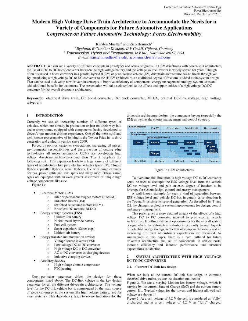
voltage components like (see
Figure 1):
• Electrical Motors (EM)
o Interior permanent magnet motors (IPMSM)
o Induction motors (IM)
o Switched reluctance motors (SRM)
o Brushless DC motors (BLDC)
• Energy storage systems (ESS)
o Lithium-Ion battery
o Nickel-metal-hydride battery
o Fuel cell system
o Super capacitors (Super-caps)
o Lithium-air battery
• Energy transfer and modulation devices
o Voltage source inverter (VSI)
o Low voltage DC to DC converter
o High voltage DC to DC converter
o AC to DC converter as charging devices
o Inductive charging devices
• Auxiliary devices
o High voltage climate compressor
o PTC heating
One particular parameter drives the design for those
components, listed above. The DC-link voltage is the key design
parameter for all the different drivetrain architectures. The voltage
level for the DC-link vehicle bus is commanded by the main source
of electrical energy in the system (the high voltage battery, and for
most systems). This dependency leads to severe limitations for the
drivetrain architecture design, the component layout (especially the
EM) as well as the energy management and control strategy.
Figure 1: x-EV architectures
To overcome this limitation, a high voltage DC to DC converter
could be used to decouple the ESS voltage level from the vehicle
DC-bus voltage level and gain an extra degree of freedom to be
leverage for system design, control and energy management.
A well-known example for such a kind of separation between
ESS voltage level and vehicle DC-bus in certain drive situation is
the Toyota Prius since its second generation. As described in [1] and
[2], the changes resulted in system improvements for design, control
and energy management.
This paper gives a more detailed insight of the effects of a high
voltage DC to DC converter induced to pure electric vehicle
architecture. It outlines different opportunities for the overall system
design, which the automotive industry is presently facing. Aspects
of potential energy savings, reduction of components variety and an
increasing fulfilment of customer expectations are discussed. As
summarized in this paper, there is a path outlined for future
drivetrain architecture and set of components to reduce costs,
increase efficiency and increase performance and customer
expectations satisfaction.
2. SYSTEM ARCHITECTURE WITH HIGH VOLTAGE
DC TO DC CONVERTER
2.1. Current DC-link bus design
When we look at the current DC-link bus design in common
electrical drive trains, we see the situation outlined in
Figure 2. We see a varying Lithium-Ion battery voltage, which is
varying by the current State of Charge (SoC) and the current battery
current IBat. Typical values for the lowest and highest allowed cell
voltage are shown in
Figure 2. At a cell voltage of 3.2 V the cell is considered as “fully”
discharged and at a cell voltage of 4.2 V as “fully” charged.
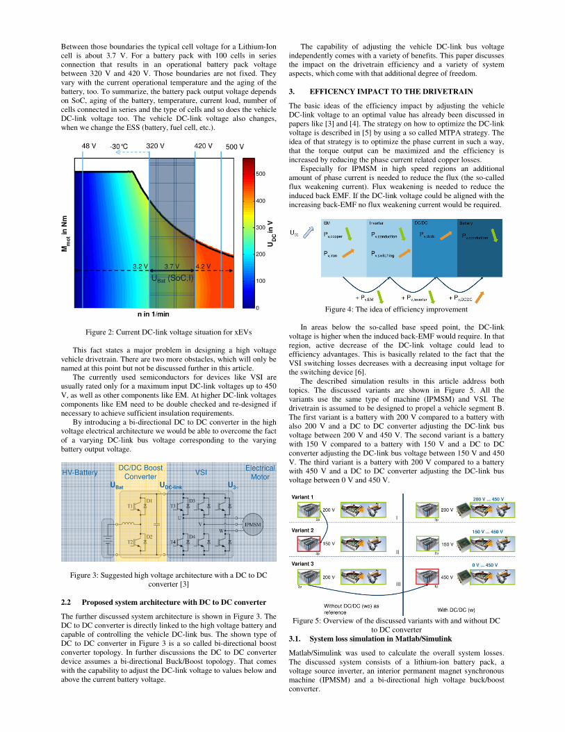
Between those boundaries the typical cell voltage for a Lithium-Ion
cell is about 3.7 V. For a battery pack with 100 cells in series
connection that results in an operational battery pack voltage
between 320 V and 420 V. Those boundaries are not fixed. They
vary with the current operational temperature and the aging of the
battery, too. To summarize, the battery pack output voltage depends
on SoC, aging of the battery, temperature, current load, number of
cells connected in series and the type of cells and so does the vehicle
DC-link voltage too. The vehicle DC-link voltage also changes,
when we change the ESS (battery, fuel cell, etc.).
Figure 2: Current DC-link voltage situation for xEVs
This fact states a major problem in designing a high voltage
vehicle drivetrain. There are two more obstacles, which will only be
named at this point but not be discussed further in this article.
The currently used semiconductors for devices like VSI are
usually rated only for a maximum input DC-link voltages up to 450
V, as well as other components like EM. At higher DC-link voltages
components like EM need to be double checked and re-designed if
necessary to achieve sufficient insulation requirements.
By introducing a bi-directional DC to DC converter in the high
voltage electrical architecture we would be able to overcome the fact
of a varying DC-link bus voltage corresponding to the varying
battery output voltage.
Figure 3: Suggested high voltage architecture with a DC to DC
converter [3]
2.2 Proposed system architecture with DC to DC converter
The further discussed system architecture is shown in Figure 3. The
DC to DC converter is directly linked to the high voltage battery and
capable of controlling the vehicle DC-link bus. The shown type of
DC to DC converter in Figure 3 is a so called bi-directional boost
converter topology. In further discussions the DC to DC converter
device assumes a bi-directional Buck/Boost topology. That comes
with the capability to adjust the DC-link voltage to values below and
above the current battery voltage.
The capability of adjusting the vehicle DC-link bus voltage
independently comes with a variety of benefits. This paper discusses
the impact on the drivetrain efficiency and a variety of system
aspects, which come with that additional degree of freedom.
3. EFFICENCY IMPACT TO THE DRIVETRAIN
The basic ideas of the efficiency impact by adjusting the vehicle
DC-link voltage to an optimal value has already been discussed in
papers like [3] and [4]. The strategy on how to optimize the DC-link
voltage is described in [5] by using a so called MTPA strategy. The
idea of that strategy is to optimize the phase current in such a way,
that the torque output can be maximized and the efficiency is
increased by reducing the phase current related copper losses.
Especially for IPMSM in high speed regions an additional
amount of phase current is needed to reduce the flux (the so-called
flux weakening current). Flux weakening is needed to reduce the
induced back EMF. If the DC-link voltage could be aligned with the
increasing back-EMF no flux weakening current would be required.
Figure 4: The idea of efficiency improvement
In areas below the so-called base speed point, the DC-link
voltage is higher when the induced back-EMF would require. In that
region, active decrease of the DC-link voltage could lead to
efficiency advantages. This is basically related to the fact that the
VSI switching losses decreases with a decreasing input voltage for
the switching device [6].
The described simulation results in this article address both
topics. The discussed variants are shown in Figure 5. All the
variants use the same type of machine (IPMSM) and VSI. The
drivetrain is assumed to be designed to propel a vehicle segment B.
The first variant is a battery with 200 V compared to a battery with
also 200 V and a DC to DC converter adjusting the DC-link bus
voltage between 200 V and 450 V. The second variant is a battery
with 150 V compared to a battery with 150 V and a DC to DC
converter adjusting the DC-link bus voltage between 150 V and 450
V. The third variant is a battery with 200 V compared to a battery
with 450 V and a DC to DC converter adjusting the DC-link bus
voltage between 0 V and 450 V.
Figure 5: Overview of the discussed variants with and without DC
to DC converter
3.1. System loss simulation in Matlab/Simulink
Matlab/Simulink was used to calculate the overall system losses.
The discussed system consists of a lithium-ion battery pack, a
voltage source inverter, an interior permanent magnet synchronous
machine (IPMSM) and a bi-directional high voltage buck/boost
converter.
3.1.1 IPMSM loss calculation
The lion share of losses in an IPMSM is caused by copper losses
and iron losses (hysteresis and eddy current losses). At low/mid
speed regions (below the rated speed) the copper losses are
dominant compared to the iron losses. At mid/high-speed regions
the iron losses have overcome the copper losses and become
dominant. Besides the copper and iron losses also eddy current
losses in the magnets and friction losses need to be taken into
account.
The iron losses can either be calculated by using the Steinmetz
equation [9] or by numerical calculations (FEM). For this paper the
IPMSM was designed for a rated voltage of 200 V and the
calculations were executed with Opera FEM. As result of the FEM
analysis the iron losses, magnetic losses, copper losses and drag
losses were separated. By post-processing the FEM results maps for
each loss share were created reflecting the dependencies on phase
current, voltage and rotational speed [8]:
��,��~��� � �1�
��,� ,��~��2�
��,� , ���~���3�
��,�~���4�
The total IPMSM machine losses result in:
��,�� � ��,�� ���,� ���,� ���,�����5�
3.1.2. Power electronic loss calculation
For the targeted application the losses for the voltage source inverter
and the DC to DC converter need to be calculated. The overall
losses for both components consist of switching and conduction
losses of the IGBTs. Conduction losses of interconnections or the
power consumption of the the device itself are neglected.
The IGBT losses of the voltage source inverter and DC to DC
converter were calculated according to [3], [6]. The conduction
losses consist of the conduction losses of each IGBT and the
corresponding freewheeling diode in the half bridge. The switching
losses are derived from the datasheet of the estimated IGBTs.
The current conduction losses of the DC to DC converter depend
on the current battery current. The battery current is not constant and
varies with the efficiency of the overall system. During the
calculation of the conduction losses a starting value for the battery
current has to be assumed. With the updated value for the
conduction losses of the DC to DC converter the battery current will
get updated and the conduction losses need to be updated too. After
multiple iterations the calculation of the conduction losses for the
dc/dc converter settles and the calculation can move on.
The sum of all conduction losses and switching losses results in
the overall power electronics losses
��,� � ��, !" ���,#$�#$�6�
3.1.2. Battery loss calculation
Also the battery losses within the system are taken into account for
the overall system losses with and without a DC to DC converter.
Only conduction losses of the battery are calculated and a varying
internal battery resistance by temperature and state of charge are
neglected.
��,&�' � (&�' ∗ �&�'� �7�
3.1.3 Overall system loss calculation
In order to calculate the overall system losses the sub-system
losses for power electronics, electrical machine and battery are
summed up for each operation point:
�� � ��,� ���,�� � ��,&�' �8�
A Matlab script is used to calculate the optimal phase current
and angle by using a MTPA strategy. The Matlab script allows you
to either calculate the MTPA trajectories for a fixed battery voltage
or for a DC-link voltage within certain boundaries. Within the
boundaries the DC-link voltage is optimized by the script to
minimize the DC-link voltage and phase current for the requested
torque output of the machine.
The step by step calculation of the overall system losses in each
operation point is according:
Step 1: Execute MTPA strategy to calculate required phase
current, phase voltage and dc voltage
Step 2: Calculate IPMSM losses based on phase current, phase
voltage, rotational speed
Step 3: Calculate voltage source inverter losses based on phase
current and phase voltage and dc voltage
Step 4: Calculate DC to DC converter losses based on dc
current, dc voltage, battery current and battery voltage
Step 5: Calculate battery losses based on battery current
Step 6: Summation of all loss shares following equation (8)
With the descried procedures to calculate the machine, power
electronic and battery losses the overall system losses are calculated
and listed in the next section of this paper.
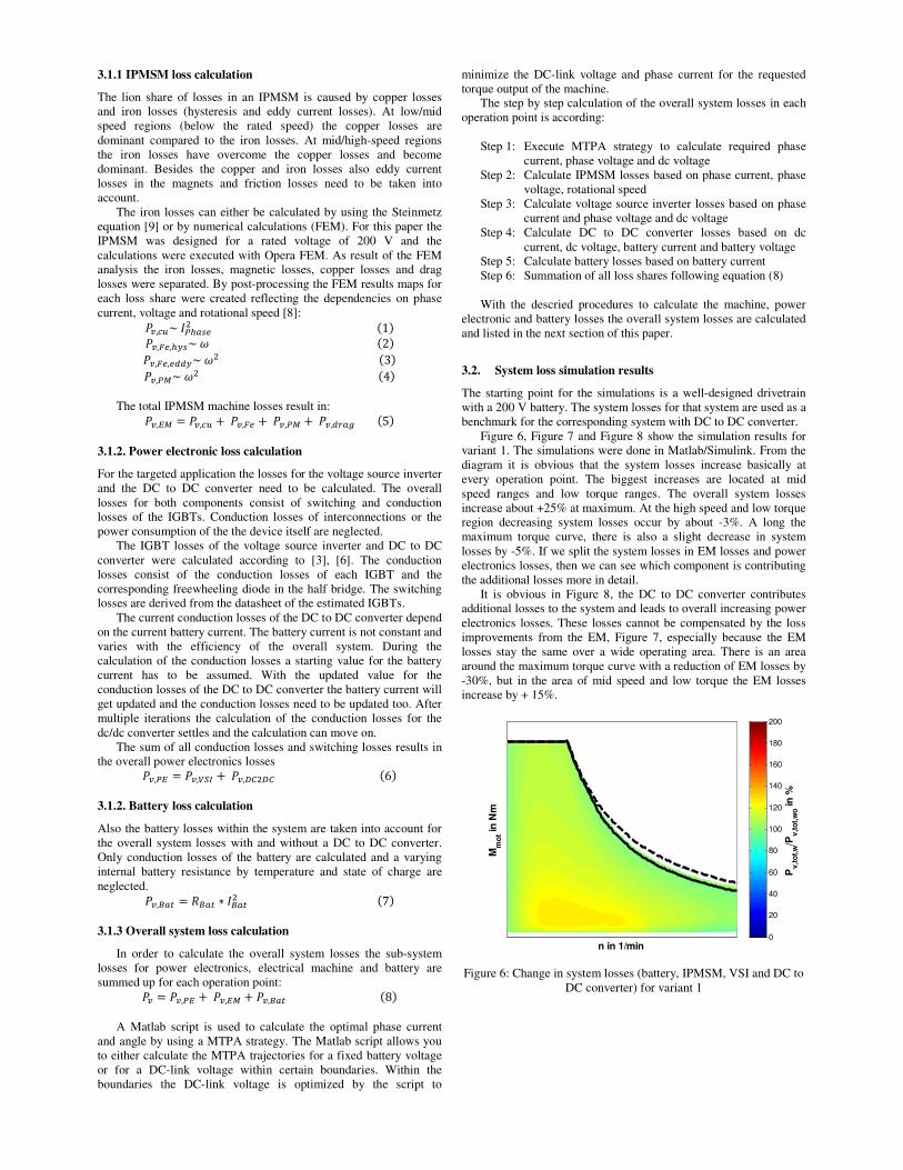
3.2. System loss simulation results
The starting point for the simulations is a well-designed drivetrain
with a 200 V battery. The system losses for that system are used as a
benchmark for the corresponding system with DC to DC converter.
Figure 6, Figure 7 and Figure 8 show the simulation results for
variant 1. The simulations were done in Matlab/Simulink. From the
diagram it is obvious that the system losses increase basically at
every operation point. The biggest increases are located at mid
speed ranges and low torque ranges. The overall system losses
increase about +25% at maximum. At the high speed and low torque
region decreasing system losses occur by about -3%. A long the
maximum torque curve, there is also a slight decrease in system
losses by -5%. If we split the system losses in EM losses and power
electronics losses, then we can see which component is contributing
the additional losses more in detail.
It is obvious in Figure 8, the DC to DC converter contributes
additional losses to the system and leads to overall increasing power
electronics losses. These losses cannot be compensated by the loss
improvements from the EM, Figure 7, especially because the EM
losses stay the same over a wide operating area. There is an area
around the maximum torque curve with a reduction of EM losses by
-30%, but in the area of mid speed and low torque the EM losses
increase by + 15%.
Figure 6: Change in system losses (battery, IPMSM, VSI and DC to
DC converter) for variant 1
n in 1/min
Mm
ot i
n N
m
Pv
,to
t,w
/Pv
,to
t,w
o in
%
0
20
40
60
80
100
120
140
160
180
200
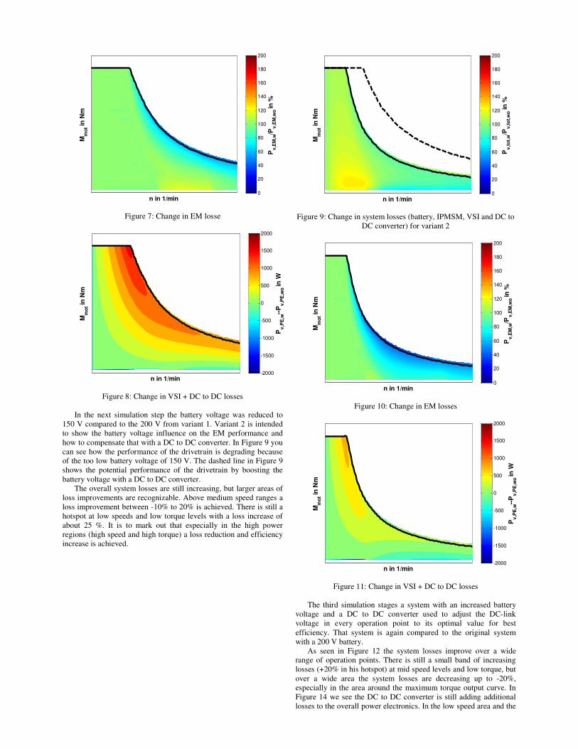
Figure 7: Change in EM losse
Figure 8: Change in VSI + DC to DC losses
In the next simulation step the battery voltage was reduced to
150 V compared to the 200 V from variant 1. Variant 2 is intended
to show the battery voltage influence on the EM performance and
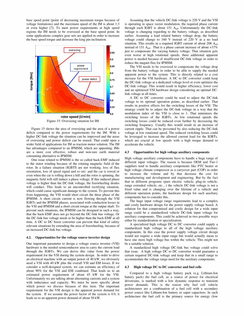
how to compensate that with a DC to DC converter. In Figure 9 you
can see how the performance of the drivetrain is degrading because
of the too low battery voltage of 150 V. The dashed line in Figure 9
shows the potential performance of the drivetrain by boosting the
battery voltage with a DC to DC converter.
The overall system losses are still increasing, but larger areas of
loss improvements are recognizable. Above medium speed ranges a
loss improvement between -10% to 20% is achieved. There is still a
hotspot at low speeds and low torque levels with a loss increase of
about 25 %. It is to mark out that especially in the high power
regions (high speed and high torque) a loss reduction and efficiency
increase is achieved.
Figure 9: Change in system losses (battery, IPMSM, VSI and DC to
DC converter) for variant 2
Figure 10: Change in EM losses
Figure 11: Change in VSI + DC to DC losses
The third simulation stages a system with an increased battery
voltage and a DC to DC converter used to adjust the DC-link
voltage in every operation point to its optimal value for best
efficiency. That system is again compared to the original system
with a 200 V battery.
As seen in Figure 12 the system losses improve over a wide
range of operation points. There is still a small band of increasing
losses (+20% in his hotspot) at mid speed levels and low torque, but
over a wide area the system losses are decreasing up to -20%,
especially in the area around the maximum torque output curve. In
Figure 14 we see the DC to DC converter is still adding additional
losses to the overall power electronics. In the low speed area and the
n in 1/min
Mm
ot i
n N
m
Pv
,EM
,w/P
v,E
M,w
o in
%
0
20
40
60
80
100
120
140
160
180
200
n in 1/min
Mm
ot i
n N
m
Pv
,PE
,w--
Pv
,PE
,wo in
W
-2000
-1500
-1000
-500
0
500
1000
1500
2000
n in 1/min
Mm
ot i
n N
m
Pv
,to
t,w
/Pv
,to
t,w
o in
%
0
20
40
60
80
100
120
140
160
180
200
n in 1/min
Mm
ot i
n N
m
Pv
,EM
,w/P
v,E
M,w
o in
%
0
20
40
60
80
100
120
140
160
180
200
n in 1/min
Mm
ot i
n N
m
Pv
,PE
,w--
Pv
,PE
,wo in
W
-2000
-1500
-1000
-500
0
500
1000
1500
2000
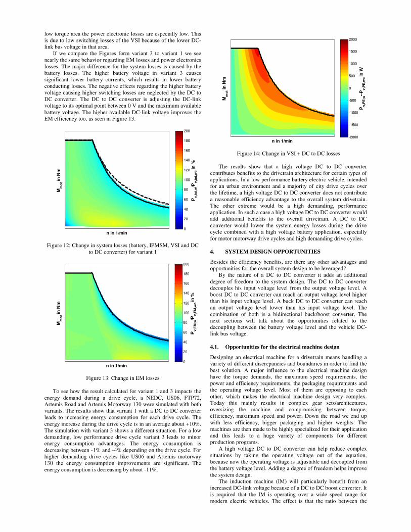
low torque area the power electronic losses are especially low. This
is due to low switching losses of the VSI because of the lower DC-
link bus voltage in that area.
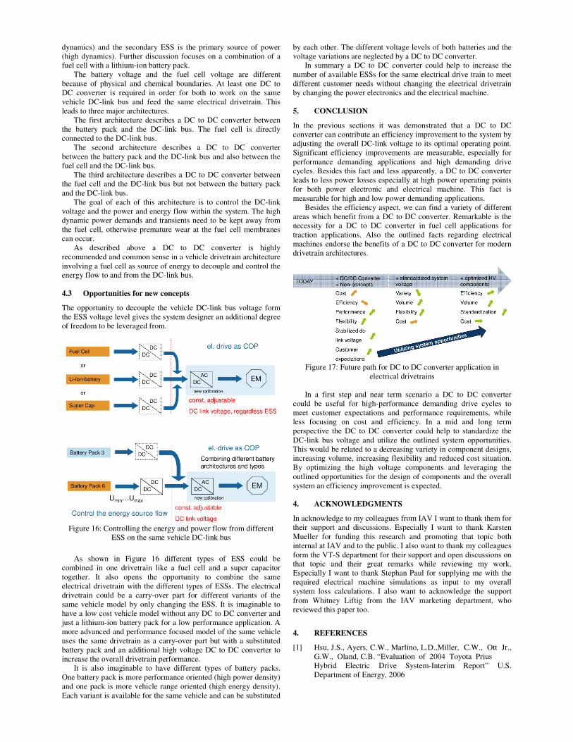
If we compare the Figures form variant 3 to variant 1 we see
nearly the same behavior regarding EM losses and power electronics
losses. The major difference for the system losses is caused by the
battery losses. The higher battery voltage in variant 3 causes
significant lower battery currents, which results in lower battery
conducting losses. The negative effects regarding the higher battery
voltage causing higher switching losses are neglected by the DC to
DC converter. The DC to DC converter is adjusting the DC-link
voltage to its optimal point between 0 V and the maximum available
battery voltage. The higher available DC-link voltage improves the
EM efficiency too, as seen in Figure 13.
Figure 12: Change in system losses (battery, IPMSM, VSI and DC
to DC converter) for variant 1
Figure 13: Change in EM losses
To see how the result calculated for variant 1 and 3 impacts the
energy demand during a drive cycle, a NEDC, US06, FTP72,
Artemis Road and Artemis Motorway 130 were simulated with both
variants. The results show that variant 1 with a DC to DC converter
leads to increasing energy consumption for each drive cycle. The
energy increase during the drive cycle is in an average about +10%.
The simulation with variant 3 shows a different situation. For a low
demanding, low performance drive cycle variant 3 leads to minor
energy consumption advantages. The energy consumption is
decreasing between -1% and -4% depending on the drive cycle. For
higher demanding drive cycles like US06 and Artemis motorway
130 the energy consumption improvements are significant. The
energy consumption is decreasing by about -11%.
Figure 14: Change in VSI + DC to DC losses
The results show that a high voltage DC to DC converter
contributes benefits to the drivetrain architecture for certain types of
applications. In a low performance battery electric vehicle, intended
for an urban environment and a majority of city drive cycles over
the lifetime, a high voltage DC to DC converter does not contribute
a reasonable efficiency advantage to the overall system drivetrain.
The other extreme would be a high demanding, performance
application. In such a case a high voltage DC to DC converter would
add additional benefits to the overall drivetrain. A DC to DC
converter would lower the system energy losses during the drive
cycle combined with a high voltage battery application, especially
for motor motorway drive cycles and high demanding drive cycles.
4. SYSTEM DESIGN OPPORTUNITIES
Besides the efficiency benefits, are there any other advantages and
opportunities for the overall system design to be leveraged?
By the nature of a DC to DC converter it adds an additional
degree of freedom to the system design. The DC to DC converter
decouples his input voltage level from the output voltage level. A
boost DC to DC converter can reach an output voltage level higher
than his input voltage level. A buck DC to DC converter can reach
an output voltage level lower than his input voltage level. The
combination of both is a bidirectional buck/boost converter. The
next sections will talk about the opportunities related to the
decoupling between the battery voltage level and the vehicle DC-
link bus voltage.
4.1. Opportunities for the electrical machine design
Designing an electrical machine for a drivetrain means handling a
variety of different discrepancies and boundaries in order to find the
best solution. A major influence to the electrical machine design
have the torque demands, the maximum speed requirements, the
power and efficiency requirements, the packaging requirements and
the operating voltage level. Most of them are opposing to each
other, which makes the electrical machine design very complex.
Today this mainly results in complex gear sets/architectures,
oversizing the machine and compromising between torque,
efficiency, maximum speed and power. Down the road we end up
with less efficiency, bigger packaging and higher weights. The
machines are then made to be highly specialized for their application
and this leads to a huge variety of components for different
production programs.
A high voltage DC to DC converter can help reduce complex
situations by taking the operating voltage out of the equation,
because now the operating voltage is adjustable and decoupled from
the battery voltage level. Adding a degree of freedom helps improve
the system design.
The induction machine (IM) will particularly benefit from an
increased DC-link voltage because of a DC to DC boost converter. It
is required that the IM is operating over a wide speed range for
modern electric vehicles. The effect is that the ratio between the
n in 1/min
Mm
ot i
n N
m
Pv
,to
t,w
/Pv
,to
t,w
o in
%
0
20
40
60
80
100
120
140
160
180
200
n in 1/min
Mm
ot i
n N
m
Pv
,EM
,w/P
v,E
M,w
o in
%
0
20
40
60
80
100
120
140
160
180
200
n in 1/min
Mm
ot i
n N
m
Pv
,PE
,w--
Pv
,PE
,wo in
W
-2000
-1500
-1000
-500
0
500
1000
1500
2000
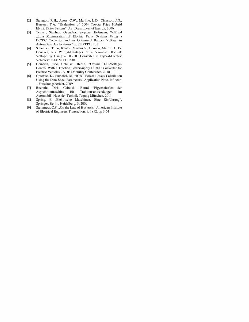
base speed point (point of decreasing maximum torque because of
voltage limitations) and the maximum speed of the IM is about 1:3
or even higher [7]. To meet power requirements at high speed
regions the IM needs to be oversized at the base speed point. In
some applications complex gear sets are applied in order to increase
the base speed torque and decrease the king pin inclination.
Figure 15: Oversizing situation for IM
Figure 15 shows the area of oversizing and the area of a power
deficit compared to the power requirements for the IM. With a
higher DC-link voltage the situation can be improved and the areas
of oversizing and power deficit can be erased. That could open a
wider field of applications for IM as traction motor solution. The IM
has advantages compared to an IPMSM, which are appealing. IMs
are a more cost effective, robust and non-rare earth material
consuming alternative to IPMSM.
One issue related to IPMSM is the so called back-EMF induced
to the stator winding because of the rotating magnetic field of the
rotor. In a failure situation (IGBTS are not working, loss of flux
orientation, loss of speed signal and so on) and the car is towed or
even when the car is rolling down a hill and the rotor is spinning, the
magnetic field will still induce a phase voltage. If this induced phase
voltage is higher than the DC-link voltage, the freewheeling diodes
will conduct. This leads to an uncontrolled rectifying situation,
which could cause significant damage to the system. To prevent this
from happening, the VSI would short circuit the three phase of the
IPMSM. A short circuit current is now flowing through the VSI
IGBTs and the IPMSM phases, associated with conduction losses in
the VSI and IPMSM and a short circuit torque at the output shaft. To
prevent such situations, the IPMSM can be designed in such a way,
that the back-EMF does not go beyond the DC-link bus voltage. Or
the DC-link bus voltage needs to be higher than the back-EMF at all
time. A DC to DC boost converter can prevent that kind of safety
relevant situations by extending the area of freewheeling, because of
an increased DC-link bus voltage.
4.2. Opportunities for the voltage source inverter design
One important parameter to design a voltage source inverter (VSI)
hardware is the needed semiconductor area to carry the current load
through the IGBTs. We can derive this value from the power
requirement for the VSI during the system design. In order to drive
an electrical machine with an output power of 40 kW, we obviously
need a VSI with 40 kW plus the overall VSI and EM losses. If we
consider a well-designed system, we can estimate an efficiency of
about 90% for the VSI and EM combined. That leads us to an
estimated power requirement of about 45 kW for the VSI.
Unfortunately we are talking about alternating currents and a system
with inductance and capacity. We must be more specific about
which power we discuss because of this item. The important
requirement for the VSI design is the apparent power demand for
the system. If we assume the power factor of the system is 0.9, it
leads us to an apparent power demand of about 50 kW.
Assuming that the vehicle DC-link voltage is 220 V and the VSI
is operating in space vector modulation, the required phase current
through each IGBT is about 151 Aeff. Unfortunately the DC-link
voltage is changing regarding to the battery voltage, as described
earlier. Assuming a load related battery voltage drop, the battery
voltage could change to 160 V instead of 220 V at a no load
situation. This results in a required IGBT current of about 208 Aeff
instead of 151 Aeff. That is a phase current increase of about +37%
just to compensate the varying battery voltage. That situation gets
even worse at high rotational speeds, there additional apparent
power is needed because of insufficient DC-link voltage in order to
reduce the magnet flux for IPMSM.
The VSI needs to be oversized to compensate the voltage drop
from the battery voltage in order to be able to supply the needed
apparent power to the system. This is directly related to a cost
increase for the VSI hardware. A DC to DC converter could keep
the DC-link voltage at a dedicated voltage level or even optimize the
DC-link voltage. This would result in higher efficiency, lower cost
and an optimized VSI hardware design considering an optimal DC-
link voltage at all times.
A DC to DC converter could be used to adjust the DC-link
voltage to its optimal operation points, as described earlier. That
results in positive effects for the switching losses of the VSI. The
strategy could be to adjust the DC-link voltage in a way that the
modulation index of the VSI is close to 1. That minimizes the
switching losses of the IGBTs. At low rotational speeds the
switching losses could be reduced even further by decreasing the
switching frequency. Usually this would result in an increase of
current ripple. That can be prevented by also reducing the DC-link
voltage at low rotational speed. The reduced switching losses could
be leveraged to increase the allowed current load for the IGBTs,
which are crucial at low speeds with a high torque demand to
accelerate the vehicle.
4.3 Opportunities for high voltage auxiliary components
High voltage auxiliary components have to handle a huge range of
different input voltages. The reason is because OEM and Tier-1
suppliers tend to handle auxiliary components like PTC heater or
high voltage climate compressor as a carryover part (COP) in order
to increase the volume and by that decrease the cost for
manufacturing and development and engineering. But by the fact
that in different programs (pure electric vehicle, plug-in vehicle,
range extended vehicle, etc…) the vehicle DC-link voltage is not a
fixed value and is changing over the lifetime of a vehicle and
different operation points, the hardware design for such auxiliary
components has to consider this.
The huge input voltage range requirements lead to a complex
and costly hardware design for the power supply voltage board. A
solution for that compromised and costly design for a wide input
range could be a standardized vehicle DC-link input voltage for
auxiliary components. This could be achieved in two possible ways
either by standardization or specialization.
A specialized high voltage DC to DC converter could supply a
standardized high voltage to all of the high voltage auxiliary
components. In this case the power supply voltage circuit design
would not require a wide input range but would actually mean to
have one more high voltage bus within the vehicle. This might not
be a suitable solution.
A standardized high voltage DC-link bus voltage could solve
that issue. A high voltage DC to DC converter would guarantee a
certain required DC-link voltage and keep that in a small range to
accommodate the voltage range need for the auxiliary components.
4.3 High voltage DC to DC converter and fuel cells
Compared to a high voltage battery pack (e.g. Lithium-Ion
battery pack) the fuel cell, as a source of power for electrical
drivetrains, is marked with a low dynamic response to transient
power demands. This is the reason why fuel cell vehicle
architectures are a combination of a fuel cell with a secondary
power source like Lithium-Ion battery or super capacitors. In such
architecture the fuel cell is the primary source for energy (low
dynamics) and the secondary ESS is the primary source of power
(high dynamics). Further discussion focuses on a combination of a
fuel cell with a lithium-ion battery pack.
The battery voltage and the fuel cell voltage are different
because of physical and chemical boundaries. At least one DC to
DC converter is required in order for both to work on the same
vehicle DC-link bus and feed the same electrical drivetrain. This
leads to three major architectures.
The first architecture describes a DC to DC converter between
the battery pack and the DC-link bus. The fuel cell is directly
connected to the DC-link bus.
The second architecture describes a DC to DC converter
between the battery pack and the DC-link bus and also between the
fuel cell and the DC-link bus.
The third architecture describes a DC to DC converter between
the fuel cell and the DC-link bus but not between the battery pack
and the DC-link bus.
The goal of each of this architecture is to control the DC-link
voltage and the power and energy flow within the system. The high
dynamic power demands and transients need to be kept away from
the fuel cell, otherwise premature wear at the fuel cell membranes
can occur.
As described above a DC to DC converter is highly
recommended and common sense in a vehicle drivetrain architecture
involving a fuel cell as source of energy to decouple and control the
energy flow to and from the DC-link bus.
4.3 Opportunities for new concepts
The opportunity to decouple the vehicle DC-link bus voltage form
the ESS voltage level gives the system designer an additional degree
of freedom to be leveraged from.
Figure 16: Controlling the energy and power flow from different
ESS on the same vehicle DC-link bus
As shown in Figure 16 different types of ESS could be
combined in one drivetrain like a fuel cell and a super capacitor
together. It also opens the opportunity to combine the same
electrical drivetrain with the different types of ESSs. The electrical
drivetrain could be a carry-over part for different variants of the
same vehicle model by only changing the ESS. It is imaginable to
have a low cost vehicle model without any DC to DC converter and
just a lithium-ion battery pack for a low performance application. A
more advanced and performance focused model of the same vehicle
uses the same drivetrain as a carry-over part but with a substituted
battery pack and an additional high voltage DC to DC converter to
increase the overall drivetrain performance.
It is also imaginable to have different types of battery packs.
One battery pack is more performance oriented (high power density)
and one pack is more vehicle range oriented (high energy density).
Each variant is available for the same vehicle and can be substituted
by each other. The different voltage levels of both batteries and the
voltage variations are neglected by a DC to DC converter.
In summary a DC to DC converter could help to increase the
number of available ESSs for the same electrical drive train to meet
different customer needs without changing the electrical drivetrain
by changing the power electronics and the electrical machine.
5. CONCLUSION
In the previous sections it was demonstrated that a DC to DC
converter can contribute an efficiency improvement to the system by
adjusting the overall DC-link voltage to its optimal operating point.
Significant efficiency improvements are measurable, especially for
performance demanding applications and high demanding drive
cycles. Besides this fact and less apparently, a DC to DC converter
leads to less power losses especially at high power operating points
for both power electronic and electrical machine. This fact is
measurable for high and low power demanding applications.
Besides the efficiency aspect, we can find a variety of different
areas which benefit from a DC to DC converter. Remarkable is the
necessity for a DC to DC converter in fuel cell applications for
traction applications. Also the outlined facts regarding electrical
machines endorse the benefits of a DC to DC converter for modern
drivetrain architectures.
Figure 17: Future path for DC to DC converter application in
electrical drivetrains
In a first step and near term scenario a DC to DC converter
could be useful for high-performance demanding drive cycles to
meet customer expectations and performance requirements, while
less focusing on cost and efficiency. In a mid and long term
perspective the DC to DC converter could help to standardize the
DC-link bus voltage and utilize the outlined system opportunities.
This would be related to a decreasing variety in component designs,
increasing volume, increasing flexibility and reduced cost situation.
By optimizing the high voltage components and leveraging the
outlined opportunities for the design of components and the overall
system an efficiency improvement is expected.
4. ACKNOWLEDGMENTS
In acknowledge to my colleagues from IAV I want to thank them for
their support and discussions. Especially I want to thank Karsten
Mueller for funding this research and promoting that topic both
internal at IAV and to the public. I also want to thank my colleagues
form the VT-S department for their support and open discussions on
that topic and their great remarks while reviewing my work.
Especially I want to thank Stephan Paul for supplying me with the
required electrical machine simulations as input to my overall
system loss calculations. I also want to acknowledge the support
from Whitney Liftig from the IAV marketing department, who
reviewed this paper too.
4. REFERENCES
[1] Hsu, J.S., Ayers, C.W., Marlino, L.D.,Miller, C.W., Ott Jr.,
G.W., Oland, C.B. “Evaluation of 2004 Toyota Prius
Hybrid Electric Drive System-Interim Report” U.S.
Department of Energy, 2006
[2] Staunton, R.H., Ayers, C.W., Marlino, L.D., Chiasson, J.N.,
Burress, T.A. “Evaluation of 2004 Toyota Prius Hybrid
Elctric Drive System” U.S. Department of Energy, 2006
[3] Tenner, Stephan, Guenther, Stephan, Hofmann, Wilfried
„Loss Minimization of Electric Drive Systems Using a
DC/DC Converter and an Optimized Battery Voltage in
Automotive Applications “ IEEE VPPC, 2011
[4] Schoenen, Timo, Kunter, Markus S., Hennen, Martin D., De
Doncker, Rik W. „Advantages of a Variable DC-Link
Voltage by Using a DC-DC Converter in Hybrid-Electric
Vehicles” IEEE VPPC, 2010
[5] Heinrich, Rico, Cebulski, Bernd, “Optimal DC-Voltage-
Control With a Traction PowerSupply DC/DC Converter for
Electric Vehicles”, VDE eMobility Conference, 2010
[6] Graovac, D., Pürschel, M. “IGBT Power Losses Calculation
Using the Data-Sheet Parameters” Application Note, Infineon
– Forschungsbericht, 2009
[7] Bochnia, Dirk, Cebulski, Bernd “Eigenschaften der
Asynchronmaschine für Traktionsanwendungen im
Automobil“ Haus der Technik Tagung München, 2011
[8] Spring, E „Elektrische Maschinen. Eine Einführung“,
Springer, Berlin, Heidelberg, 3, 2009
[9] Steinmetz, C.P. „On the Law of Hystersis“ American Institute
of Electrical Engineers Transaction, 9, 1892, pp 3-64