MODELS SDR AND SDL - ENVIRO-TEC MODELS SDR AND SDL SDR SDL. 2 ENVIRO-TEC FORM ET130.13-NOM1 (519)...
16
INSTALLATION, OPERATION & MAINTENANCE SINGLE DUCT VAV TERMINALS Supersedes: ET130.13-NOM1 (615) Form ET130.13-NOM1 (519) MODELS SDR AND SDL SDR SDL
Transcript of MODELS SDR AND SDL - ENVIRO-TEC MODELS SDR AND SDL SDR SDL. 2 ENVIRO-TEC FORM ET130.13-NOM1 (519)...
INSTALLATION, OPERATION & MAINTENANCE
SINGLE DUCT VAV TERMINALS
Supersedes: ET130.13-NOM1 (615) Form ET130.13-NOM1 (519)
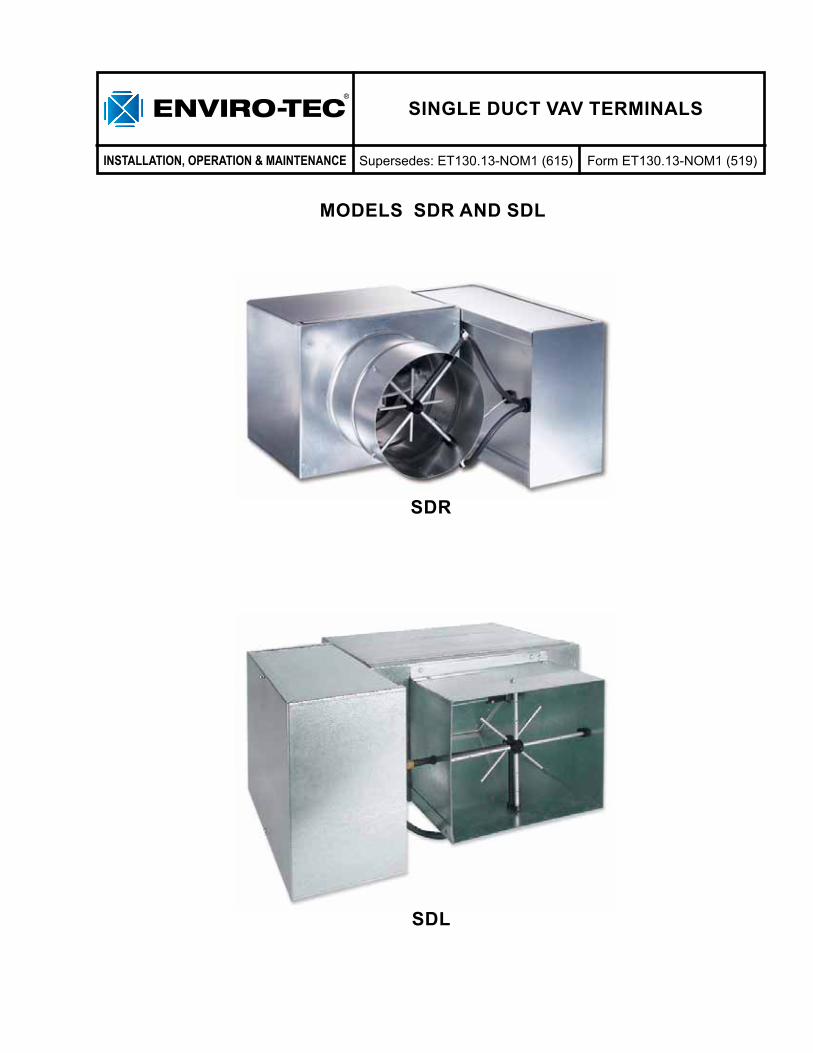
MODELS SDR AND SDL
SDR
SDL
ENVIRO-TEC2
FORM ET130.13-NOM1 (519)
SAFETY CONSIDERATIONS .....................................................................................................................3INSPECTION ................................................................................................................................................4STORAGE ....................................................................................................................................................4PRE-INSTALLATION INSPECTION ..........................................................................................................5SEQUENCE OF OPERATION ....................................................................................................................5
Single Duct .............................................................................................................................................5INSTALLATION ............................................................................................................................................5
Clearances .............................................................................................................................................5Hanging and Mounting Equipment ......................................................................................................5Unit Weights ...........................................................................................................................................6Duct Connections ..................................................................................................................................6Critically Sound Applications ...............................................................................................................7Coil Connections ...................................................................................................................................7Electrical .................................................................................................................................................7
OPERATION .................................................................................................................................................7Start-Up ..................................................................................................................................................73 Phase Balancing .................................................................................................................................7
MAINTENANCE ...........................................................................................................................................8Optional Damper Actuator ....................................................................................................................8Manual Override ....................................................................................................................................8Mechanical Angle of Rotation Stops ...................................................................................................8External Terminal Strip .........................................................................................................................8Overload Protection ..............................................................................................................................8Checkout Instructions ...........................................................................................................................8Damper Shaft .........................................................................................................................................8Coil ..........................................................................................................................................................8
Cleaning ............................................................................................................................................9 Electric Heat ..........................................................................................................................................9
Minimum Operating Conditions ......................................................................................................9Electric Heater Rack Replacement .................................................................................................9Electric Heater Element Replacement ............................................................................................9Heater Troubleshooting Guide ......................................................................................................10(SSR) Troubleshooting Guide .......................................................................................................11
Calibration Charts ...............................................................................................................................15
TABLE OF CONTENTS
ENVIRO-TEC 3
FORM ET130.13-NOM1 (519)
SAFETY SYMBOLS
The following symbols are used in this document to alert the reader to areas of potential hazard:
CAUTION identifies a hazard which could lead to damage to the machine, damage to other equipment and/or environmental pollution. Usually an instruction will be given, together with a brief explanation.
NOTE is used to highlight additional information which may be helpful to you.
DANGER indicates an imminently hazardous situation which, if not avoided, will result in death or serious injury.
WARNING indicates a potentially hazardous situation which, if not avoided, could result in death or se-rious injury.
SAFETY CONSIDERATIONSThe equipment covered in this manual is designed for safe and reliable operation when installed and operated within its’ design specification limits. To avoid personal injury or damage to equipment or property while installing or operating this equipment, it is essential that qualified, experience personnel familiar with local codes and regulations, perform these functions using good judgment and safe practices. See the following cautionary statements.
ELECTRICAL SHOCK HAZARDSAll power must be disconnected prior to installation and servicing this equip-ment. More then one source of power may be present. Disconnect all power sources to avoid electrocution or shock hazards.
HOT PARTS HAZARDElectric resistance heating elements must be disconnected prior to servic-ing. Electric heaters may start auto-matically; disconnect all power and control circuits prior to servicing to avoid burns.
Check that rigging and lifting equip-ment can safely support the unit as-sembly and component weights.
All assemblies must be adequately secured during lifting and rigging by temporary supports and restraints un-til equipment is permanently fastened and set in its’ final location.
All unit temporary and permanent supports must be capable of safely supporting the equipment’s weight and any additional live, seismic or dead loads that may be encountered. All supports must be designed to meet ap-plicable local codes and ordinances.
All fastening devices must be designed to mechanically lock the assembly in place without the capability of loosen-ing or breaking away due to system operation and vibration.
Secure all dampers when servicing damper, actuators or linkage. Damp-ers may activate automatically, discon-nect control circuits or control systems to avoid injury.
Protect adjacent flammable material when brazing. Use flame and heat protection barriers where needed. Have fire extinguisher ready for im-mediate use.
ENVIRO-TEC4
FORM ET130.13-NOM1 (519)
INSPECTIONUpon receipt of equipment, carefully check all items against the bill of lading to ensure that all equipment has been received (including shipped loose items). Note any discrepancy on the bill of lading before signing.
Inspect all equipment for any signs of damage caused during transit. On units with re-heat, check the coil fins and/or ensure that the resistance heat coils are not damaged. Note any visual damage on the bill of lading before signing. Immediately report all visual and concealed damage to the carrier and file a claim with the carrier.
Locate the model number on the nameplate and check that the correct units have been received. Verify that all options have been included, such as controls, heating coils, etc. Also ensure that unit voltage agrees with the building parameters. If a discrepancy is discovered between what was ordered and received, contact your local ENVIRO-TEC representative immediately.
DO NOT USE FLOW SENSOR, CONNECTING TUBES, COIL STU-BOUTS OR DAMPER SHAFT AS A HANDLE WHEN LIFTING OR MOVING EQUIPMENT, AS DAM-AGE MAY OCCUR.
DO NOT HANDLE EQUIPMENT’S HEATING ELEMENTS, AS PERMA-NENT DAMAGE MAY OCCUR.
CHECK assembly and component weights to be sure that the rigging equipment can handle them safely. Note; also check the centers of gravity and any specific rigging instructions.
CHECK for adequate ventilation so fumes do not migrate through ductwork to occupied spaces when welding or cutting around the unit.
DO NOT work on damper until associ-ated actuator is disconnected.
NEVER pressurize equipment above specified test pressure.
PROTECT adjacent flammable ma-terials when brazing. Use flame and heat protection barriers where needed. Have a fire extinguisher at hand and ready for immediate use.
STORAGEIf equipment is to be stored prior to installation, observe the following precautions:
1. Choose a dry storage site that is reasonably level and sturdy to prevent undue stress or permanent damage to the equipment. Set equipment off ground if in moisture prone areas.
2. Tag and store in a safe place until needed. Cover entire equipment with protective tarp or moisture proof cover. Extend cover under equipment if stored on ground. Secure cover with adequate tie downs and store indoors. Be sure that piping con-nections have protective shipping caps installed.
ENVIRO-TEC 5
FORM ET130.13-NOM1 (519)
PRE-INSTALLATION INSPECTION
DO NOT USE FLOW SENSOR, CONNECTING TUBES, COIL STU-BOUTS OR DAMPER SHAFT AS A HANDLE WHEN LIFTING OR MOVING EQUIPMENT, AS DAM-AGE MAY OCCUR.
DO NOT HANDLE EQUIPMENT’S HEATING ELEMENTS, AS PERMA-NENT DAMAGE MAY OCCUR.
Ensure that all linkages are connected properly. Check the linkage that connects the actuator to the damper shaft to ensure that the nuts are tight.
While viewing the damper from the discharge of the unit, rotate the shaft fully. The damper should close fully and there should be no gaps between the damper gasketing and the inside of the valve.
SEQUENCE OF OPERATIONSingle Duct
The basic unit consists of a sheet metal casing and an air valve, which is used to modulate the air being delivered into the occupied zone. Air enters the air valve inlet and exits into the sheet metal casing to be distributed to the occupied zone through ductwork attached to the discharge of the unit.
The basic unit can be ordered with either a factory mounted hot water heating coil or an electric heater.
These re-heat units are used primarily to reheat the air-to-zone temperature when the load in the occupied space drops off.
The primary air is modulated through the FlowStar™ air valve by rotating the damper blade. The air valves come in rectangular and round. The round valves only come in diameters of 4, 5, 6, 8, 10, 12, 14 and 16 inches; an adapter must be used for metric ductwork.
INSTALLATION
DO NOT USE FLOW SENSOR, CONNECTING TUBES, COIL STU-BOUTS OR DAMPER SHAFT AS A HANDLE WHEN LIFTING OR MOVING EQUIPMENT, AS DAM-AGE MAY OCCUR.
DO NOT HANDLE EQUIPMENT’S HEATING ELEMENTS, AS PERMA-NENT DAMAGE MAY OCCUR.
All terminal equipment with electric heaters must be installed in a horizontal plane with respect to the airflow stream. Low height equipment (Model SDL) can be flipped over in the field to vary or change control section handing.
Clearances
All equipment covered in this document, including those with electric heat, are ETL listed for 0.0" clearance to combustibles. Refer to NEC and/or local codes for minimum electrical clearances required for service. Equipment should not make contact with any structure located above the equipment without appropriate isolation. Equipment supplied with bottom access panels requires sufficient clearance to access fasteners, and to lower and slide panel horizontally until clear of bottom of unit.
Hanging and Mounting Equipment
Although the basic equipment is generally light enough that it can be supported by the ductwork, ENVIRO-TEC strongly recommends that all equipment be suspended from the upper most ceiling or a structural element of the building, independent of the false ceiling grid. Suspension devises are field supplied, sized and designed by others. ENVIRO-TEC will not accept responsibility for unit support. Equipment must be installed in a level horizontal plane. Failure to level equipment properly may prevent proper operation of controls. Provisions for proper support in seismically active regions is the responsibility of others. See table 1 through 4 for unit weights.
ENVIRO-TEC6
FORM ET130.13-NOM1 (519)
UNIT WEIGHTS
When requested, equipment is supplied with optional hanger brackets for use with up to a 3/8" diameter hanger rod. See submittal drawings for hanger bracket locations.
Hanger straps may be utilized as an alternate means of suspending the equipment. Do not secure hanger straps to electric heaters, coils or control enclosures. Hanger straps can be mounted directly to the sides and bottom of equipment casing, such that they do not interfere with working components or access panels, using screws that do not penetrate the unit cabinet more than 3/8".
When hanging equipment, always use the support method as prescribed for rectangular duct in the job specifications.
Duct Connections
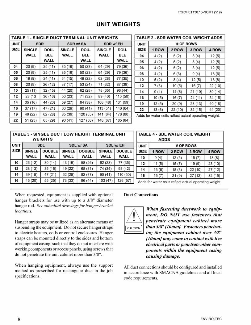
When fastening ductwork to equip-ment, DO NOT use fasteners that penetrate equipment cabinet more than 3/8" [10mm]. Fasteners penetrat-ing the equipment cabinet over 3/8" [10mm] may come in contact with live electrical parts or penetrate other com-ponents within the equipment casing causing damage.
All duct connections should be configured and installed in accordance with SMACNA guidelines and all local code requirements.
TABLE 4 - SDL WATER COIL WEIGHT ADDSUNIT SIZE
# OF ROWS1 ROW 2 ROW 3 ROW 4 ROW
10 9 (4) 12 (5) 15 (7) 18 (8)12 11 (5) 15 (7) 19 (9) 23 (10)14 13 (6) 18 (8) 22 (10) 27 (12)16 15 (7) 21 (9) 27 (12) 32 (15)
Adds for water coils reflect actual operating weight.
TABLE 1 - SINGLE DUCT TERMINAL UNIT WEIGHTSUNIT SIZE
SDR SDR w/ SA SDR w/ EHSINGLE WALL
DOU-BLE
WALL
SINGLE WALL
DOU-BLE
WALL
SINGLE WALL
DOU-BLE
WALL04 20 (9) 25 (11) 35 (16) 50 (23) 64 (29) 79 (36)05 20 (9) 25 (11) 35 (16) 50 (23) 64 (29) 79 (36)06 19 (9) 24 (11) 34 (15) 49 (22) 62 (28) 77 (35}08 20 (9) 26 (12) 37 (17) 53 (24) 71 (32) 87 (39)10 25 (11) 32 (15) 44 (20) 62 (28) 78 (35) 96 (44)12 28 (13 36 (16) 50 (23) 71 (32) 89 (40) 110 (50)14 35 (16) 44 (20) 59 (27) 84 (38) 106 (48) 131 (59)16 37 (17) 47 (21) 63 (29) 90 (41) 113 (51) 140 (64)19 49 (22) 62 (28) 85 (39) 120 (55) 141 (64) 176 (80)22 51 (23) 65 (29) 90 (41) 127 (58) 148 (67) 185 (84)
TABLE 2 - SDR WATER COIL WEIGHT ADDSUNIT SIZE
# OF ROWS1 ROW 2 ROW 3 ROW 4 ROW
04 4 (2) 5 (2) 8 (4) 12 (5)05 4 (2) 5 (2) 8 (4) 12 (5)06 4 (2) 5 (2) 8 (4) 12 (5)08 4 (2) 6 (3) 9 (4) 13 (6)10 5 (2) 8 (4) 12 (5) 18 (8)12 7 (3) 10 (5) 16 (7) 22 (10)14 9 (4) 14 (6) 21 (10) 30 (14)16 10 (5) 16 (7) 24 (11) 34 (15)19 12 (5) 20 (9) 28 (13) 40 (18)22 13 (6) 22 (10) 32 (15) 44 (20)
Adds for water coils reflect actual operating weight.
TABLE 3 - SINGLE DUCT LOW HEIGHT TERMINAL UNIT WEIGHTSUNIT SIZE
SDL SDL w/ SA SDL w/ EHSINGLE WALL
DOUBLE WALL
SINGLE WALL
DOUBLE WALL
SINGLE WALL
DOUBLE WALL
10 26 (12) 30 (14) 43 (19) 58 (26) 62 (28) 77 (35)12 28 (13) 35 (16) 49 (22) 68 (31) 74 (34) 93 (42)14 39 (18) 47 (21) 62 (28) 82 (37) 90 (41) 110 (50)16 45 (20) 55 (25) 73 (33) 96 (44) 103 (47) 126 (57)
ENVIRO-TEC 7
FORM ET130.13-NOM1 (519)
Allow a minimum of 1½-duct diameters of straight duct prior to equipment inlet and equipment discharge. The diameter of the inlet duct for round valves must be equal to the listed size of the equipment. The round air valve inlet collar of the equipment is 1/8" smaller then listed size in order to allow the round ductwork to slip over the air valve inlet collar. DO NOT INSERT DUCTWORK INTO AIR VALVE INLET COLLAR. When making ductwork connection to air valve inlet collar and insulating air valve inlet, take caution not to damage or remove the flow sensor connections, which are vital to unit control. Provide insulation around entire inlet collar (all the way to the equipment casing).
Permissible discharge duct connections are straight flanged, slip and drive or drive and screw.
If equipment is to be installed in a location with high humidity, external insulation around the heating coil should be installed.
Sound Critical Applications
Flexible duct connectors are not recommended on equipment discharge. The sagging membrane of these fittings can cause turbulence and higher air velocities that generate noise. Also, lightweight membrane material allows noise to breakout, which can increase sound levels in the space below.
Coil Connections
Hot water and steam coils are male sweat connections. Use appropriate brazing alloy for system temperature and pressure. Refer to unit construction submittal drawing for specific connection size. MAXIMUM HYDRONIC SYSTEM OPERATING PRESSURE MUST NOT EXCEED 300 PSIG. MAXIMUM STEAM SYSTEM PRESSURE MUST NOT EXCEED 15 PSIG.
Electrical
All field wiring must comply with NEC and all local codes. Electrical and/or control wiring diagrams are located on the control enclosure box. All electric heaters are staged per specifications.
The installing electrician should rotate the incoming electric service by phase to help balance the building electrical load.
Minimum circuit ampacity (MCA) designates the maximum operating load of the equipment for sizing wire feeders. Fuse size of the internal fuse if supplied. Maximum Overcurrent Protection (MOP) designates the largest breaker or fuse in the electrical service panel that can be used to protect the equipment.
Use Copper conductors only.
OPERATIONStart-Up
Thorough safety precautions should always be taken when performing startup and service. Only qualified individuals should perform these tasks.
Check that all electrical work is finished and properly terminated. Check that all electrical connections are tight and that the proper voltage is connected.
3 Phase Balancing
AC power imbalance must not exceed 2%. Be sure that the following guides are met:
1. AC power is within 10% of rated voltage at rated frequency. (See equipment nameplate for rat-ings).
2. AC power is within 5% of rated frequency at rated voltage.
3. A combined variation in the voltage and frequency of 10% (sum of absolute values) of rated values, provided the frequency variation does not exceed 5% of rated frequency.
Equipment with electric heat requires a minimum of 0.1" w.g. downstream static pressure.
Prior to start-up, the project control sequence/wiring diagram should be obtained and thoroughly understood. If factory supplied analog or DDC controls are utilized, refer to the applicable Operation Manual for start-up and balancing information.
ENVIRO-TEC8
FORM ET130.13-NOM1 (519)
MAINTENANCEOptional Damper Actuator
An optional factory mounted floating type actuator is available, which mounts directly to the damper operating shaft. The actuator is not provided with and does not require any limit switches but is electronically protected against overload.
Manual Override
A button on the side of the actuator cover disengages the gear train so the drain shaft can be moved manually. Releasing the button will re-engage the gear train.
Mechanical Angle of Rotation Stops
The adjustable stops may be field adjusted to halt the rotation of the damper blade before the damper blade reaches the damper stops. The actuator can be indefinitely stalled in any position without harm.
1. Loosen the two end stop screws using a No. 2 Phillips head screwdriver, being careful not to unscrew the captive nut under the slot.
2. Move the stops (in 2.5° steps) to the desired posi-tion and retighten the screws.
External Terminal Strip
The external terminal strip is located on the top of the actuator. Connections are numbered. The terminals are designed for 26 to 16 gauge wires. For most installations, 18 or 16 gauge wire will work well with the actuator (see table 5 for maximum wire lengths).
Overload Protection
The actuators are electronically protected against mechanical overload. In the actuator, an electronic circuit maintains the current at a level that will not damage the motor while providing adequate holding torque.
Checkout Instructions
1. Disconnect actuator from the controller.2. Apply 24 VAC to the COM and CW terminals on
the actuator. Actuator should rotate in a clockwise direction.
3. Apply 24 VAC to the COM and CCW terminals on the actuator. Actuator should rotate in a counter clockwise direction.
4. If actuator moves in both directions, it is opera-tional.
5. If the actuator does not rotate, it may be at an end stop or there is a problem with the damper.
6. Loosen the set screw to free the actuator from the damper shaft. Check to make sure that the damper shaft rotates freely.
7. Check to make sure that actuator is not against stop. Repeat steps 2 and 3.
8. If actuator does not rotate, replace.
Damper Shaft
There is an indicator on the end of the damper shaft that can be used to determine the position of the damper blade. If the indicator is horizontal, the damper is completely open. The damper shaft is ½" diameter.
Coil
The frequency of required cleaning is dependent on the operating hours of the system, filter maintenance and efficiency as well as dirt load.
Important: Coils may become exter-nally dirty as result of normal opera-tion. Dirt on the surface of the coil reduces its ability to transfer heat that can result in reduced performance, and increased operating energy cost. If the dirt on the surface of the coil becomes wet, microbial growth (mold) can result, possibly causing unpleas-ant odors and serious health related indoor air quality problems.
Fin edges are sharp. Fins are fragile; care must be exercised to avoid damag-ing fins. Do not use solutions to clean coils; drain pans are not present to remove collected solution.
TABLE 5 - MAXIMUM WIRE LENGTHSWIRE SIZE MAX FEET
16 GA 1225 FT18 GA 725 FT20 GA 400 FT22 GA 200 FT
ENVIRO-TEC 9
FORM ET130.13-NOM1 (519)
Cleaning1. Disconnect all electrical power to the equipment,
tag and lock out power source.2. Gain access to coil either through ductwork or
optional coil access panel. 3. Use soft brush and vacuum to remove loose debris
from sides of coil. Do not use fluid or solvents to clean coils, as no provisions for collecting liquids exist on this type of equipment.
4. Straighten any coil fins that may have been dam-aged during cleaning process with fin comb.
5. Replace ductwork or access panel and restore electrical power to equipment.
Electric Heat
ENVIRO-TEC electric heaters require little or no maintenance.
Electric heaters come equipped with a primary auto-reset limit switch. These limit switches provide protection against overheating. The auto-reset limits switches automatically cut the heater off when overheating occurs, and turns the heater back on when the elements have cooled down. Electric heaters also come equipped with a secondary one-time trip limit switch. Should the secondary limit switches trip, they will need to be replaced with a limit switch that has the same trip temperature as the one-time trip limit switch that was originally supplied with the electric heater. An optional manual reset secondary is available, which can be reset by depressing the reset switch.
Minimum Operating Conditions
Airflow must be at least 70 CFM per kW. A minimum of 0.1" w.g. external pressure is required.
Electric Heater Rack Replacement
ENVIRO-TEC HEATERS
1. Turn off power supply before servicing.2. Locate T-Plate inside on heater control enclo-
sure.3. Before removing wires from the element rack
T-Plate, mark where the wires are connected so that they can be reconnected correctly on the new element rack.
4. Remove the wires and screws holding the heater T-plate in the control enclosure and remove ele-ment rack.
5. Insert new element rack into control enclosure and replace screws to secure the element rack to control enclosure.
6. Replace wires.7. Close control enclosure cover before turning on
the power.
Electric Heater Element ReplacementTUTCO HEATERS
1. Turn off power supply before servicing.2. Disconnect field wiring from Electric Heater Con-
trol Enclosure.3. Disconnect Amp Plug Connectors if equipped.4. Remove 4 mounting screws from inside Electric
Heater Control Enclosure.5. Slide entire heater assembly out of Single Duct
Terminal.6. Remove wires and any jumpers from heater ele-
ment terminal ends, noting which wire and jumper goes to which terminal.
7. Remove ¼" hex head screws located near terminal ends.
8. Remove ¼" hex head screws from opposite of terminal end on heater rack.
9. Remove elements and replace with new ones.10. Reassemble, replace wires correctly.11. Close control enclosure cover before turning on
power.

ENVIRO-TEC10
FORM ET130.13-NOM1 (519)
ELECTRIC HEATER TROUBLESHOOTING GUIDEENVIRO-TEC AND TUTCO
TABLE 6 - HEATER TROUBLESHOOTING GUIDE
Check wiring diagrams to ensure that heater is properly wired.SYMPTOM POSSIBLE CAUSE CORRECTIVE ACTION
HEATER DOES NOT OPERATE
No Power Check Disconnect.
No Control VoltageCheck Control Signal (i.e. 24 VAC).Check transformer and transformer fus-ing (if applicable), replace if necessary.
Blown Fuse Replace fuse.
Open Limit (primary or secondary)Replace limits or reset as applicable.Check for continuity across limit to de-termine if open, replace as necessary.
Airflow Incorrect Direction Check sensing tube, rotate if needed.Low Airflow Static Pressure Increase airflow.
Damaged ElementsCheck for open or damaged elements and replace as necessary.
LOW OR HIGH TEMPERATURE RISE
Incompatible Thermostat or ControllerCheck Wiring.Check for compatibility.
Problems with Additional Stages
Check location of thermostat; may be installed in a “too hot” or “too cold loca-tion. Check heat outputs on controller.Check contactors for open coil.Check for damaged elements.
Incorrect CFMCheck for blocked duct or location of heater.
SHORT CYCLINGImproper Airflow
Check for even airflow across the face of the element section.Check for blocked duct.Verify installation per SMACNA and ASHRAE guidelines.Check for dirty filters.
Low CFMSee remedies for “Improper Airflow”.Check air velocity of 70 CFM per kW.
HEATER WITH SSR DOES NOT OPERATE
Incorrect Signal Applied Verify signal input.Interface Board Fuse Blown Replace fuse.See SSR Troubleshooting (next page)
ENVIRO-TEC 11
FORM ET130.13-NOM1 (519)
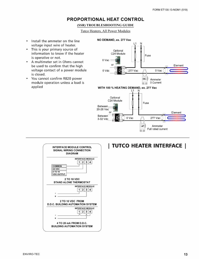
PROPORTIONAL HEAT CONTROL (SSR) TROUBLESHOOTING GUIDE
ENVIRO-TEC Heaters
Lethal voltages are present in the heater control enclosure. Use extreme caution when taking measurements in these units. Always disconnect power before removing or re-applying any connections.
1. Before applying power, verify wiring matches diagram in cover of heater control enclosure, and that correct line voltage has been wired to heater line block.
2. Verify 24 VAC +15% or -10% between P1 and P2 of interface circuit board (ETPHCI, ETPHCV2, etc., depending on input).
3. The table below lists responses to input signal by interface model as explained in step 4. If any of these inputs cannot be obtained, refer to the litera-ture on the device that is supposed to provide the input. Otherwise, proceed to step 4.
INTERFACEMODEL
“PULSE”INPUT
FULL OFF
INPUT
FULL ON
INPUTINPUTS
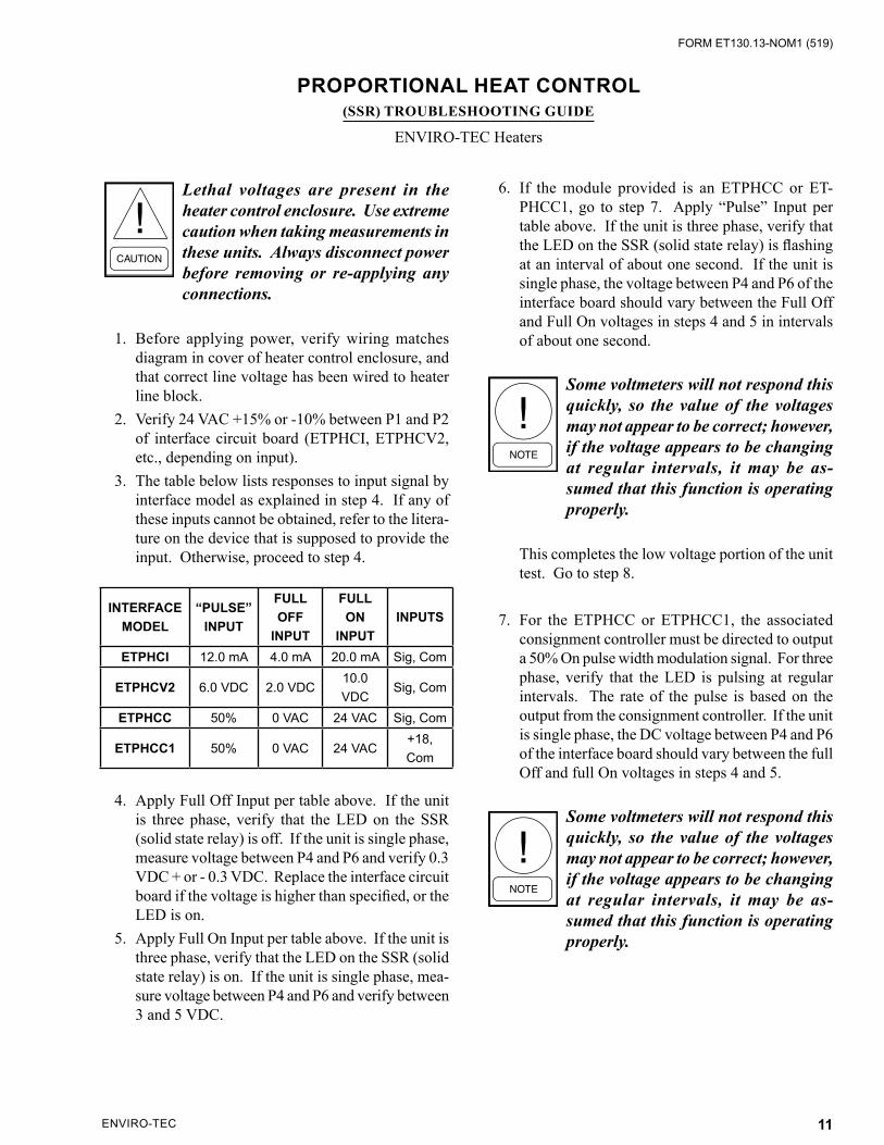
ETPHCI 12.0 mA 4.0 mA 20.0 mA Sig, Com
ETPHCV2 6.0 VDC 2.0 VDC10.0 VDC
Sig, Com
ETPHCC 50% 0 VAC 24 VAC Sig, Com
ETPHCC1 50% 0 VAC 24 VAC+18, Com
4. Apply Full Off Input per table above. If the unit is three phase, verify that the LED on the SSR (solid state relay) is off. If the unit is single phase, measure voltage between P4 and P6 and verify 0.3 VDC + or - 0.3 VDC. Replace the interface circuit board if the voltage is higher than specified, or the LED is on.
5. Apply Full On Input per table above. If the unit is three phase, verify that the LED on the SSR (solid state relay) is on. If the unit is single phase, mea-sure voltage between P4 and P6 and verify between 3 and 5 VDC.
6. If the module provided is an ETPHCC or ET-PHCC1, go to step 7. Apply “Pulse” Input per table above. If the unit is three phase, verify that the LED on the SSR (solid state relay) is flashing at an interval of about one second. If the unit is single phase, the voltage between P4 and P6 of the interface board should vary between the Full Off and Full On voltages in steps 4 and 5 in intervals of about one second.
Some voltmeters will not respond this quickly, so the value of the voltages may not appear to be correct; however, if the voltage appears to be changing at regular intervals, it may be as-sumed that this function is operating properly.
This completes the low voltage portion of the unit test. Go to step 8.
7. For the ETPHCC or ETPHCC1, the associated consignment controller must be directed to output a 50% On pulse width modulation signal. For three phase, verify that the LED is pulsing at regular intervals. The rate of the pulse is based on the output from the consignment controller. If the unit is single phase, the DC voltage between P4 and P6 of the interface board should vary between the full Off and full On voltages in steps 4 and 5.
Some voltmeters will not respond this quickly, so the value of the voltages may not appear to be correct; however, if the voltage appears to be changing at regular intervals, it may be as-sumed that this function is operating properly.
ENVIRO-TEC12
FORM ET130.13-NOM1 (519)
8. If the heater always remains energized when power is applied, remove the wire from P4 of the interface circuit board. If the heat remains on, there is a wiring error or the SSR is defective.
Remove Power From the Unit Before Proceeding With the Next Step.
9. If the heater is always de-energized when power is applied, remove the line and load connections to the proportional heat control and temporarily tie them together. If the system is a three phase arrangement, do the phases one at a time.
Always remove power from the unit before moving to the next phase).
Make sure there is no danger of the temporary connection shorting to another component or the chassis. Briefly reapply power. If the section of heat under test now energizes, the SSR is defective. If heater still will not energize, one of the heater safety devices (limits, safety contactor or airflow switch) or elements is defective.
ENVIRO-TEC 13
FORM ET130.13-NOM1 (519)
PROPORTIONAL HEAT CONTROL (SSR) TROUBLESHOOTING GUIDE
Tutco Heaters, All Power Modules
ENVIRO-TEC14
FORM ET130.13-NOM1 (519)
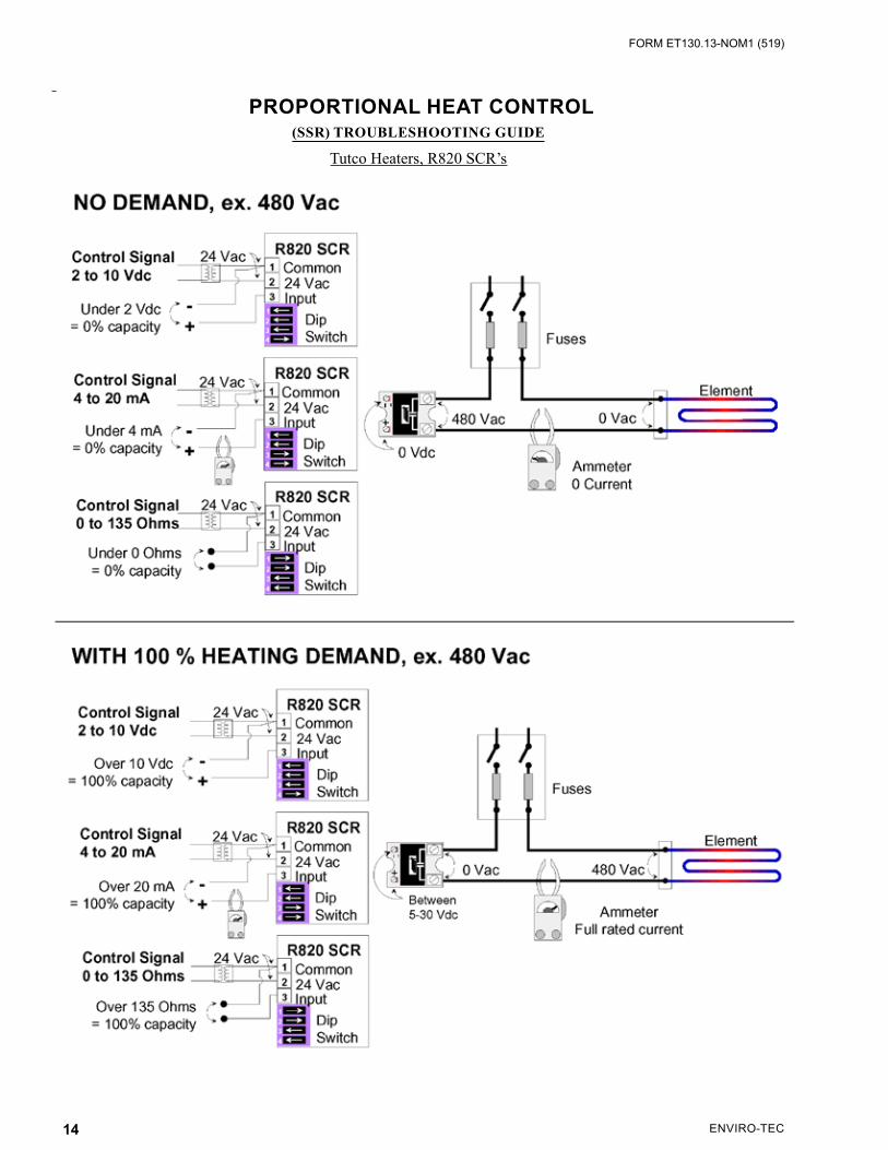
PROPORTIONAL HEAT CONTROL
(SSR) TROUBLESHOOTING GUIDE
Tutco Heaters, R820 SCR’s
ENVIRO-TEC 15
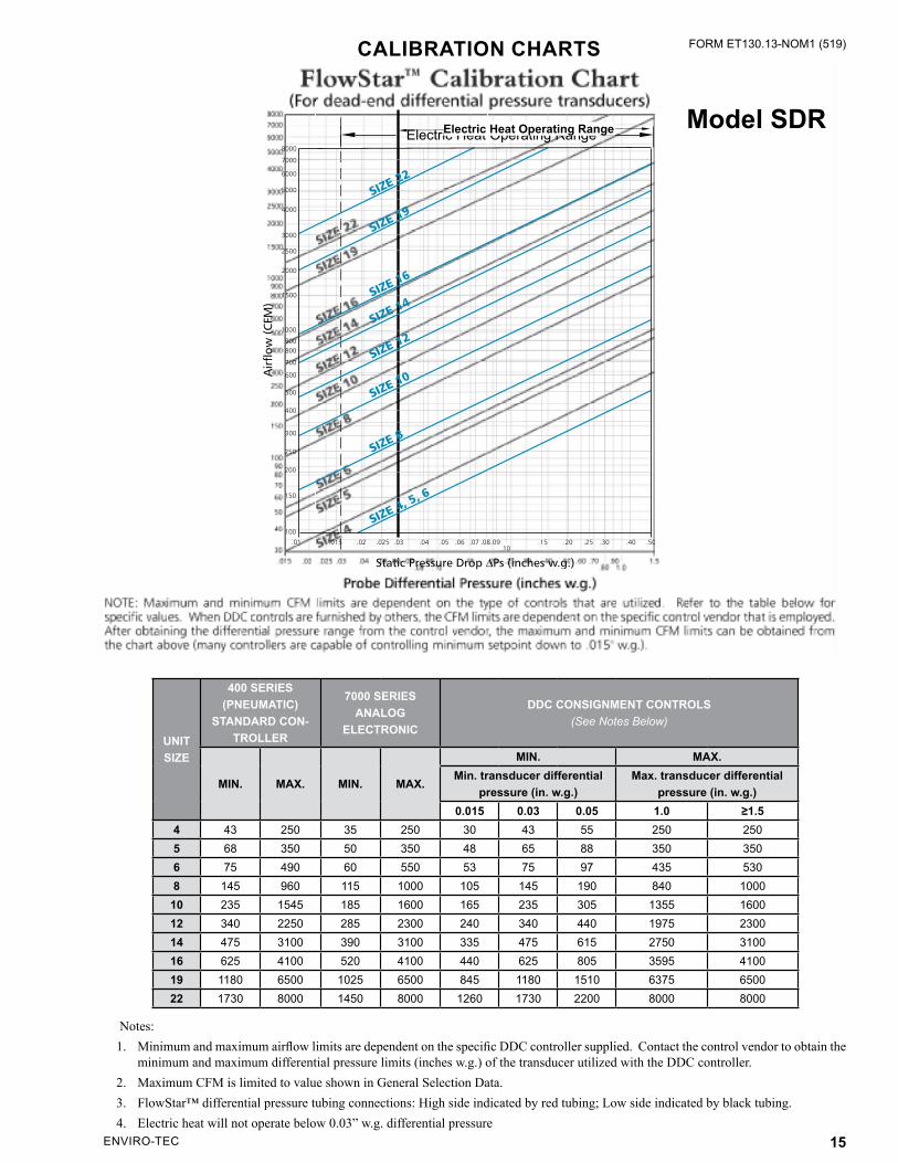
FORM ET130.13-NOM1 (519)CALIBRATION CHARTS
Notes:1. Minimum and maximum airflow limits are dependent on the specific DDC controller supplied. Contact the control vendor to obtain the
minimum and maximum differential pressure limits (inches w.g.) of the transducer utilized with the DDC controller.2. Maximum CFM is limited to value shown in General Selection Data.3. FlowStar™ differential pressure tubing connections: High side indicated by red tubing; Low side indicated by black tubing.4. Electric heat will not operate below 0.03” w.g. differential pressure
UNIT SIZE
400 SERIES(PNEUMATIC)
STANDARD CON-TROLLER
7000 SERIES ANALOG
ELECTRONIC
DDC CONSIGNMENT CONTROLS (See Notes Below)
MIN. MAX. MIN. MAX.
MIN. MAX. Min. transducer differential
pressure (in. w.g.)Max. transducer differential
pressure (in. w.g.)0.015 0.03 0.05 1.0 ≥1.5
4 43 250 35 250 30 43 55 250 2505 68 350 50 350 48 65 88 350 3506 75 490 60 550 53 75 97 435 5308 145 960 115 1000 105 145 190 840 100010 235 1545 185 1600 165 235 305 1355 160012 340 2250 285 2300 240 340 440 1975 230014 475 3100 390 3100 335 475 615 2750 310016 625 4100 520 4100 440 625 805 3595 410019 1180 6500 1025 6500 845 1180 1510 6375 650022 1730 8000 1450 8000 1260 1730 2200 8000 8000
Electric Heat Operating RangeModel SDR�����������������������������
ENVIRO-TEC is a registered trademark of Johnson Controls, Inc. in the United States of America and other countries. Other trademarks used herein may be trademarks or registered trademarks of other companies.
Catalog: ET130.13-NOM1 (519) Supersedes ET130.13-NOM1 (615)© 2019 Johnson Controls, Inc. P.O. Box 423, Milwaukee, WI 53201 Printed in USAwww.enviro-tec.com
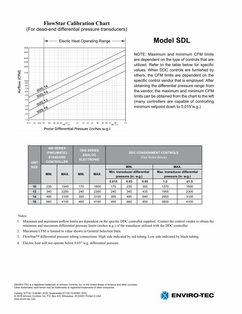
Notes:1. Minimum and maximum airflow limits are dependent on the specific DDC controller supplied. Contact the control vendor to obtain the
minimum and maximum differential pressure limits (inches w.g.) of the transducer utilized with the DDC controller.2. Maximum CFM is limited to value shown in General Selection Data.3. FlowStar™ differential pressure tubing connections: High side indicated by red tubing; Low side indicated by black tubing.
4. Electric heat will not operate below 0.03” w.g. differential pressure
UNIT SIZE
400 SERIES(PNEUMATIC) STANDARD
CONTROLLER
7000 SERIES ANALOG
ELECTRONIC
DDC CONSIGNMENT CONTROLS (See Notes Below)
MIN. MAX. MIN. MAX.
MIN. MAX. Min. transducer differential
pressure (in. w.g.)Max. transducer differential
pressure (in. w.g.)0.015 0.03 0.05 1.0 ≥1.5
10 235 1545 170 1600 170 235 305 1370 160012 340 2250 240 2300 240 340 435 1955 230014 495 3100 350 3100 350 495 640 2855 310016 660 4100 465 4100 465 660 850 3800 4100
Model SDL����������������������������
FlowStar Calibration Chart(For dead-end differential pressure transducers)
NOTE: Maximum and minimum CFM limits are dependent on the type of controls that are utilized. Refer to the table below for specific values. When DDC controls are furnished by others, the CFM limits are dependent on the specific control vendor that is employed. After obtaining the differential pressure range from the vendor, the maximum and minimum CFM limits can be obtained from the chart to the left (many controllers are capable of controlling minimum setpoint down to 0.015”w.g.)