MODELS SA4, SA4-D, MA4, MA4-D, LA4, LA4-D
12
Power amplifiers QUICKSTART GUIDE MODELS | SA4, SA4-D, MA4, MA4-D, LA4, LA4-D
Transcript of MODELS SA4, SA4-D, MA4, MA4-D, LA4, LA4-D

Power amplifiers
QUICKSTART GUIDE
MODELS | SA4, SA4-D, MA4, MA4-D, LA4, LA4-D

2 JBL DSI SERIES POWER AMPLIFIERS
IMPORTANT SAFETY INSTRUCTIONSIMPORTANTES INSTRUCTIONS DE SÉCURITÉWICHTIGE SICHERHEITSINSTRUKTIONENINSTRUCCIONES DE SEGURIDAD IMPORTANTES
1. Read these instructions.2. Keep these instructions.3. Heed all warnings.4. Follow all instructions.5. Do not use this apparatus near water.6. Clean only with a dry cloth.7. Do not block any ventilation openings. Install in
accordance with the manufacturer’s instructions.8. Do not install near any heat sources such as radiators,
heat registers, stoves, or other apparatus (including amplifiers) that produce heat.
9. Do not defeat the safety purpose of the polarized or grounding-type plug. A polarized plug has two blades with one wider than the other. A grounding-type plug has two blades and a third grounding prong. The wide blade or the third prong is provided for your safety. If the provided plug does not fit into your outlet, consult an electrician for replacement of the obsolete outlet.
10. Protect the power cord from being walked on or pinched, particularly at plugs, convenience receptacles, and the point where they exit from the apparatus.
11. Only use attachments/accessories specified by the manufacturer.
12. Use only with a cart, stand, tripod, bracket, or table specified by the manufacturer, or sold with the apparatus. When a cart is used, use caution when moving the cart/apparatus combination to avoid injury from tip-over.
13. Unplug this apparatus during lightning storms or when unused for long periods of time.
14. Refer all servicing to qualified service personnel. Servicing is required when the apparatus has been damaged in any way, such as power-supply cord or plug is damaged, liquid has been spilled or objects have fallen into the apparatus, the apparatus has been exposed to rain or moisture, does not operate normally,or has been dropped.
15. Use the mains plug to disconnect the apparatus from the mains.
16. WARNING: TO REDUCE THE RISK OF FIRE OR ELECTRIC SHOCK, DO NOT EXPOSE THIS APPARATUS TO RAIN OR MOISTURE.
17. DO NOT EXPOSE THIS EQUIPMENT TO DRIPPING OR SPLASHING AND ENSURE THAT NO OBJECTS FILLED WITH LIQUIDS, SUCH AS VASES, ARE PLACED ON THE EQUIPMENT.
18. THE MAINS PLUG OF THE POWER SUPPLY CORD SHALL REMAIN READILY OPERABLE.
TO PREVENT ELECTRIC SHOCK DO NOT REMOVE TOP OR BOTTOM COVERS. NO USER SERVICEABLE PARTS INSIDE. REFER SERVICING TO QUALIFIED SERVICE PERSONNEL.
À PRÉVENIR LE CHOC ÉLECTRIQUE N’ENLEVEZ PAS LES COUVERCLES. IL N’Y A PAS DES PARTIES SERVICEABLE À L’INTÉRIEUR. TOUS REPARATIONS DOIT ETRE FAIRE PAR PERSONNEL QUALIFIÉ SEULMENT.
PARA PREVENIR UN CHOQUE ELÉCTRICO, NO RETIRE LAS CUBIERTAS SUPERIOR O INFERIOR. NO EXISTEN PARTES QUE PUEDAN SER REPARADAS POR EL USUARIO AL INTERIOR. REMITA EL SERVICICO AL PERSONAL TÉCHNICAL CALIFICADO.
TO COMPLETELY DISCONNECT THIS EQUIPMENT FROM THE AC MAINS, DISCONNECT THE POWER SUPPLY CORD PLUG FROM THE AC RECEPTACLE. THE MAINS PLUG OF THE POWER SUPPLY CORD SHALL REMAIN READILY OPERABLE.
POUR DÉMONTER COMPLÈTEMENT L’ÉQUIPEMENT DE L’ALIMENTATION GÉNÉRALE, DÉMONTER LE CÂBLE D’ALIMENTATION DE SON RÉCEPTACLE. LA PRISE D’ALIMENTATION RESTERA AISÉMENT FONCTIONNELLE.
PARA DESCONECTAR COMPLETAMENTE EL EQUIPO DEL SUMINSTRO ELECTRICO, DESCONECTE EL CABLE DE ALIMENTACION DE LA TOMA DE CA. LAS PATAS DEL CONECTOR DEL CABLE DE ALIMENTACIÓN DEBERAN MANTENERSE EN BUEN ESTADO.
WATCH FOR THESE SYMBOLS:The lightning bolt triangle is used to alert the user to the risk of electric shock.
The exclamation point triangle is used to alert the user to important operating or maintenance instructions.
REGARDEZ CES SYMBOLES:La triangle avec le sigle ‘’foudre’’ est employée pour alerter l’utilisateur au risque de décharge électrique. Le triangle avec un point d’exclamation est employée pour alerter l’utilisateur d’instruction importantes pour lors opérations de maintenance.
ATENCION CON ESTOS SÍMBOLOS:El triángulo con el símbolo de rayo eléctrico es usado para alertar al usuario de el riesgo de un choque eléctrico. El triángulo con el signo de admiración es usado para alertar al usuario de instrucciones importantes de operación o mantenimiento.
The Centric Amplified Control System are certified only at 120V~ in Canada.
IMPORTANTSystème de contrôle Centric Amplified require Class 2 output wiring. Les amplificateurs de série de I-Tech exigent des câbles de sortie de classe 2.Centric Amplified Kontrollsystem Klasse die 2 Produktionsverdrahtung.Sistema de control amplificado central requieren de un cableado de salida Clase 2.
MAGNETIC FIELDCAUTION! Do not locate sensitive high-gain equipment such as preamplifiers directly above or below the unit. Because this amplifier has a high power density, it has a strong magnetic field which can induce hum into unshielded devices that are located nearby. The field is strongest just above and below the unit.
If an equipment rack is used, we recommend locating the amplifiers) in the bottom of the rack and the preamplifier or other sensitiv e equipment at the top.
FCC COMPLIANCE NOTICEThis device complies with part 15 of the FCC rules. Operation is subject to the following two conditions: (1) This device may not cause harmful interference, and (2) this device must accept any interference received, including interference that may cause undesired operation.
CAUTION: Changes or modifications not expressly approved by the party responsible for compliance could void the user’s authority to operate the equipment.
NOTE: This equipment has been tested and found to comply with the limits for a Class B digital device, pursuant to part 15 of the FCC Rules. These limits are designed to provide reasonable protection against harmful interference in a residential installation. This equipment generates, uses, and can radiate radio frequency energy and, if not installed and used in accordance with the instruction manual, may cause harmful interference to radio communications. However, there is no guarantee that interference will not occur in a particular installation. If this equipment does cause harmful interference to radio or television reception, which can be determined by turning the equipment off and on, the user is encouraged to try to correct the interference by one or more of the following measures:
• Reorient or relocate the receiving antenna.• Increase the separation between the equipment and
receiver.• Connect the equipment into an outlet on a circuit
different from that to which the receiver is connected.• Consult the dealer or an experienced radio/TV technician
for help.
C A U T I O NRISK OF ELECTRIC SHOCK
DO NOT OPEN
A V I SRISQUE DE CHOC ÉLECTRIQUE
N’OUVREZ PAS

3QUICK START GUIDE
Thank you for purchasing a JBL DSi 2 Cinema amplifier, one in a complete line of high-performance amplifiers based on exclusive DriveCore technology powered by Crown. The DSi 2 Series amplifiers are designed, engineered, and manufactured to the industry’s highest quality standards and offer cinema system integrators with the advanced features and flexibility required for challenging 21st-century Cinema-sound applications.
Please take the time to study the owners manual so that you can obtain the best possible service from your amplifier at http://jblpro.com.
Trademark Notice: Com-Tech, BCA, JBL, Amcron, DriveCore, Drivecore Install are Trademarks of HARMAN International..
WHATS INCLUDED1. JBL DSi 2.0 Amplifier2. 2 Phoenix Terminals for Analog Input.3. 8 Spade Lugs for Amplifier Output.4. Phoenx Terminal for GPIO.5. 1 Power cord (except for ‘-NP’ Variants)
WHAT YOU WILL NEED(not supplied):
• Input wiring cables • Output wiring cables • Flathead screwdriver • Phillips screwdriver• Rack for mounting amplifier (or a stable surface for stacking)• Category 5e or higher cabling• 1 Power cord for ‘-NP’ Models
Quick Reference Chart
Ordering Information
WELCOMEPOWER ON Press Power Button momentarily
POWER OFF Press and Hold Power button for 2s
FRONT PANEL LOCK/UNLOCK Simultaneously Press and Hold Select 1 Button and Encoder
DIAGNOSTICS SCREEN Press and Hold Encoder
ORDERING INFORMATION
SA4 SA4 Amplifier with Analog only Inputs
MA4 MA4 Amplifier with Analog only Inputs
LA4 LA4 Amplifier with Analog only Inputs SA4-D SA4 Amplifier with Analog + AES67 Inputs
MA4-DMA4 Amplifier with Analog + AES67 Inputs
LA4-D LA4 Amplifier with Analog + AES67 Inputs Suffix '- US' Amplifier Model with US power cord
Suffix '- EK'Amplifier Model with EU, UK and Korea Power cord
Suffix '- CN' Amplifier Model with China power cord
Suffix '-NP'Amplifier Model with NO power cord. Power cords may be ordered separately.
Example: SA4-D-USSA4 Amplifier with Analog + AES67 Inputs with US power cord
Example: LA4-CNLA4 Amplifier with Analog only Inputs with China power cord
Example: SA4-NPSA4 Amplifier WITHOUT any power cord (No Power cord)
Spare Analog Input Connector
(P/N 5024623).
Spare Speaker Terminal Spade Lugs
(P/N PV10-6LF-L)
4 JBL DSI SERIES POWER AMPLIFIERS
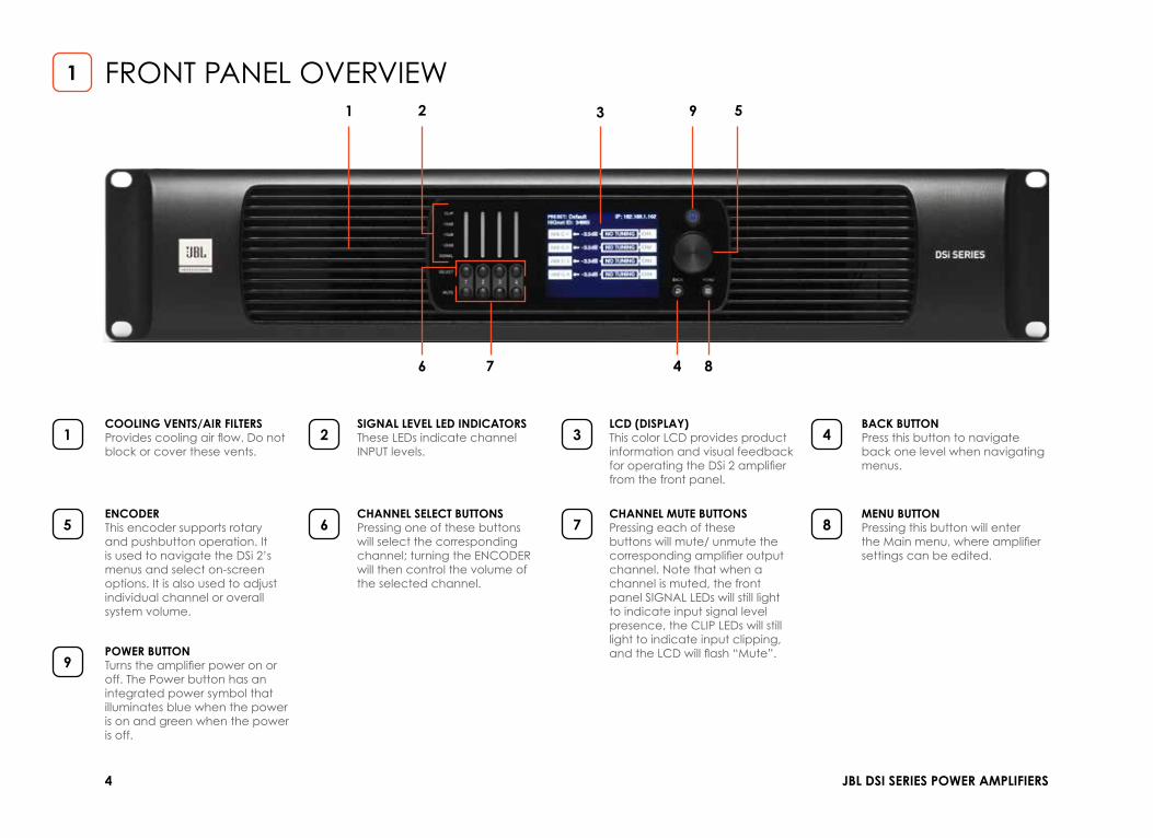
COOLING VENTS/AIR FILTERSProvides cooling air flow. Do not block or cover these vents.
SIGNAL LEVEL LED INDICATORSThese LEDs indicate channel INPUT levels.
LCD (DISPLAY)This color LCD provides product information and visual feedback for operating the DSi 2 amplifier from the front panel.
BACK BUTTONPress this button to navigate back one level when navigating menus.
ENCODERThis encoder supports rotary and pushbutton operation. It is used to navigate the DSi 2’s menus and select on-screen options. It is also used to adjust individual channel or overall system volume.
CHANNEL SELECT BUTTONSPressing one of these buttons will select the corresponding channel; turning the ENCODER will then control the volume of the selected channel.
CHANNEL MUTE BUTTONSPressing each of these buttons will mute/ unmute the corresponding amplifier output channel. Note that when a channel is muted, the front panel SIGNAL LEDs will still light to indicate input signal level presence, the CLIP LEDs will still light to indicate input clipping, and the LCD will flash “Mute”.
MENU BUTTONPressing this button will enter the Main menu, where amplifier settings can be edited.
POWER BUTTONTurns the amplifier power on or off. The Power button has an integrated power symbol that illuminates blue when the power is on and green when the power is off.
1
5
9
2
6
3
7
4
8
FRONT PANEL OVERVIEW1 2 3
4
9
87
5
6
1

5QUICK START GUIDE
COOLING VENTSDo not block/cover these vents.
AES67 PRIMARY / SECONDARY PORTSThese two RJ45 connectors are used for AES67 Audio transport and are available only on the ‘-D’ DSi 2 amplifier models. This implementation of AES67 allows for up to 64 channels of digital audio over Category 5e wiring.
GENERAL PURPOSE INPUT/OUTPUT (GPIO)This 8-pin block connector combines the 2-in, 2-out GPIO with the SLEEP and AMP STATUS pins from the AUX circuit.
ETHERNET (NETWORK CONTROL) PORTConnect this RJ45 port to a computer or network for monitoring and controlling the amplifier over Category 5e wiring via the Audio Architect software.
AC POWER INLETConnect the included AC power cord to this standard 15A, IEC type 320 inlet. Supported mains voltage range is 100-240V~.
OUTPUT TERMINAL (BARRIER BLOCK) CONNECTORSTwo four-pole, touch-proof terminal strip per channel pair. Accepts up to 10 AWG wire or terminal forks.
ANALOG AUDIO INPUT CONNECTORSConnect your audio source outputs to these inputs using the provided plug-in connectors. One 6-pin plug-in connector can be used per input pair. These inputs are high impedance, balanced connections.
1
5
2
6
3
7
4
REAR PANEL OVERVIEW1 2 34 7
6 6
75
2

6 JBL DSI SERIES POWER AMPLIFIERS
UNPACKINGUnpack your amplifier and inspect for any damage that may have occurred during transit. If damage is found, notify the shipping company immediately. Only you can initiate a claim for shipping damage, though JBL will be happy to help as needed. If the product arrived showing signs of damage, save the shipping carton for the shipper’s inspection.
We also recommend that you save all packing materials for use if you ever need to transport the unit. Never ship the unit without the factory carton and packing materials.
CAUTION: Before you begin, make sure your amplifier is disconnected from the power source.
INSTALLING THE AMPLIFIERMount the unit in a standard 19-inch (48.3 cm) equipment rack (EIA RS-310B). You can also place a single amp on a solid, stable surface or stack multiple amps.
NOTE: Amplifiers should be supported at both the front and rear of the rack.
PROPER COOLINGWhen using an equipment rack, mount units directly on top of each other. Close any open spaces in the rack with blank panels. (Open spaces will reduce cooling efficiency.) DO NOT block front or rear air vents.
The rack should be a minimum of 2 inches (5.1 cm) away from the amplifier, and the back of the rack should be a minimum of 4 inches (10.2 cm) from the amplifier back panel.
INSTALLING THE AMP3
CLIP
-10dB
-15dB
-20dB
SIGNAL
SELECT
MUTE
PRESET: DefaultHiQnet ID: 34885
BACKMENU
NO TUNINGNO TUNINGNO TUNINGNO TUNING
–3.5dB
–3.5dB
–3.5dB
–3.5dB
IP: 192.168.1.102
1 2 3 4
ANLG 1
CH1
CH2
CH3
CH4
ANLG 2
ANLG 3
ANLG 4
CLIP
-10dB
-15dB
-20dB
SIGNAL
SELECT
MUTE
PRESET: DefaultHiQnet ID: 34885
BACKMENU
NO TUNINGNO TUNINGNO TUNINGNO TUNING
–3.5dB
–3.5dB
–3.5dB
–3.5dB
IP: 192.168.1.102
1 2 3 4
ANLG 1
CH1
CH2
CH3
CH4
ANLG 2
ANLG 3
ANLG 4
CLIP
-10dB
-15dB
-20dB
SIGNAL
SELECT
MUTE
PRESET: DefaultHiQnet ID: 34885
BACKMENU
NO TUNINGNO TUNINGNO TUNINGNO TUNING
–3.5dB
–3.5dB
–3.5dB
–3.5dB
IP: 192.168.1.102
1 2 3 4
ANLG 1
CH1
CH2
CH3
CH4
ANLG 2
ANLG 3
ANLG 4
CLIP
-10dB
-15dB
-20dB
SIGNAL
SELECT
MUTE
PRESET: DefaultHiQnet ID: 34885
BACKMENU
NO TUNINGNO TUNINGNO TUNINGNO TUNING
–3.5dB
–3.5dB
–3.5dB
–3.5dB
IP: 192.168.1.102
1 2 3 4
ANLG 1
CH1
CH2
CH3
CH4
ANLG 2
ANLG 3
ANLG 4

7QUICK START GUIDE
CONNECTING THE AC POWER CORDConnect your amplifier to the AC mains power outlet using the supplied AC power cord. First, connect the IEC end of the cord to the IEC connector on the amplifier. Then plug the other end of the cord to the AC mains.
WARNING: The third (ground) prong of the supplied AC power cord connector is a required safety feature. Do not attempt to disable this ground connection by using an adapter or other methods.
Make certain the AC mains voltage and current ratings are sufficient to deliver full power to all amplifiers. DSi 2 Series amplifiers use a universal power supply. The AC voltage requirements are 100V-240V~, 50/60Hz (±10%). If the AC line voltage varies outside of this acceptable range, the amplifier’s power supply will turn off and the blue Power LED will flash. The amplifier will turn back on when the AC line voltage returns to safe operating levels.
POWER UP PROCEDUREWhen turning on the amplifier for the first time: 1. Ensure all connections are disconnected with the exception of the power cord.2. Press the amplifier’s POWER button. The Power indicator will light blue and the amplifier will boot as long as sufficient
mains power is provided.3. Once boot up is complete, turn the ENCODER counter-clockwise until all amp levels are set to -80dB in the front panel
LCD. (The Encoders affect the OUTPUT levl of hte Amplifier.)4. Configure the amplifier as described in .5. Once the amplifier has been properly configured for the application, turn off the power — by pressing and holding the
Power button for 2 seconds — then disconnect the power cord.6. Turn down the level of your audio source.7. Make all connections as described in “Wiring Input Connectors” and “Wiring Output Connectors” on page 8.8. Once all connections have been made, reconnect the power cord and turn on the amplifier power.9. Turn your audio source up to an optimum level. Refer to all device meters and ensure that at no point in the signal
chain is the signal being clipped in any way. If any of the amplifier’s Clip indicators light yellow, reduce the source level until the Clip LEDs no longer light.
10. Turn the amplifier’s ENCODER clockwise until the desired loudness or power level is achieved, while making sure the amplifier’s clip LEDs do not light.
HARDWARE SETUP4

8 JBL DSI SERIES POWER AMPLIFIERS
WIRING INPUT CONNECTORSJBL recommends using pre-built or professionally wired balanced cables (two-conductor plus shield). Balanced wiring provides better rejection of unwanted noise and hum, however, unbalanced line may also be used. Use 6-pin plug-in cable ends at the amp input connectors. A male connector is supplied for each input of your model of amplifier. Additional connectors are available from JBL (P/N 5024623). Figure 4 shows connector pin assignments for balanced wiring and Figure 5 shows connector pin assignments for unbalanced wiring. Note that for bridge mono operation, only the odd-numbered input channels (1,3) should be wired for each bridged pair.
WIRING OUTPUT CONNECTORSBefore making any output connections, ensure the power cord is disconnected from the amplifier and carefully review the total impedance for loudspeakers connected to each amplifier output. If multiple loudspeakers are connected to an output (i.e., in series, parallel, or series-parallel), be certain the total system impedance is within allowed specification for the output.
For low-impedance loads, refer to the table below and select the appropriate size of wire based on the distance from amplifier to speaker.
Figure 4b: Unbalanced wiring
SOURCE
INPUT
Figure 4a: Balanced wiring
SOURCE
INPUT
Distance Wire Size
Up to 25 ft. (7.6m) 16 AWG
26-40 ft. (7.9-12.2m) 14 AWG
41-60 ft. (12.5-18.3m) 12 AWG
> 60 ft (18.3m) 10 AWG Figure 4c: Wiring output connectors

9QUICK START GUIDE
FRONT PANEL MENUS & NAVIGATION OVERVIEW5
MENU STRUCTUREThe below diagram shows the DSI 2’s front panel menu
structure, as well as how to navigate and control channel volume.
Home Screen
Adjusts Channel 1 Volume
Adjusts Channel 2 Volume
Adjusts Channel 3 Volume
Adjusts Channel 4 Volume
Turn ENCODER
Turn ENCODER
Turn ENCODER
Turn ENCODER
Turn ENCODER
Adjusts System Volume(all channels)
Configure Amplifier System Settings Network AES67
Guided Setup
Amp Wiring(Y, Bridge)
Input Source
Output Fader Linking
Save Preset
Load Preset
Lighting / DisplayMenu
Security
Amp SensitivityMode
Power Modes
Diagnostics
Config (DHCP)
IP Address
Subnet Mask
Gateway
HiQnet Address
AES67 Status
AES67 Settings
Pre
ss M
ENU
Bu
tto
n
Pre
ss a
nd
ho
ld E
NC
OD
ERPress CH1 SELECT Button
(hold button for CH1 Info)
Press CH2 SELECT Button
(hold button for CH2 Info)
Press CH3 SELECT Button
(hold button for CH3 Info)
Press CH4 SELECT Button
(hold button for CH4 Info)
CH2 Selected
CH1 Selected
CH3 Selected
CH4 Selected
*Turn ENCODER to Scroll through options and Press to Select
AES67 Option available only on ‘-D’ Models
Speaker Tunings /DSP
AES67 Option available only on ‘-D’ Models
Home Screen
Configure Amplifier
Press MENU Button
Scroll and select Using ENCODER
Guided Setup
Amp Wiring(Y, Bridge)
Input Source
Speaker Tunings /DSP
Output Fader Linking
Save Preset
Load Preset
Input Delay
Input PEQ
Xover
Output Delay
Limiter
Speaker Tuning
Output PEQ

10 JBL DSI SERIES POWER AMPLIFIERS
THE HOME SCREENThe Home screen (shown in Figure 5a) is the first screen displayed in the DSi 2’s front panel display once the amplifier has completed the boot sequence.
From the Home screen, the ENCODER can be turned to adjust system volume or pressed and held to access the Diagnostics screen, the CHANNEL SELECT buttons can be pressed (or held) to adjust individual channel volume using the ENCODER, or the MENU button can be pressed to enter the Main menu to configure and view information about the amplifier.
The Home screen shows at-a-glance amplifier configuration information, as shown in Figure 5b. Here you can see the currently loaded device preset, device IP address, DSi 2 configuration, channel volume settings, and more.
Figure 5a: Home screen
Current Device Preset
HiQnet ID
Figure 5b: Home screen layout
Device IP Address
Channel Volume Settings
Error Messages Are Displayed Here
Configuration

11QUICK START GUIDE
DSI SERIES FEATURESPlease refer to the DSi User Guide for in depth descriptions and instruction on the following features.
CONFIGURING THE AMPRead how to configure the DSi 2 amplifier for your application using the front panel user interface. This includes assigning input channels, editing internal routing and DSP settings, and configuring output mode settings. DSi 2 Series amplifiers can be configured using the built-in Guided Setup or manually using the individual menu options in the Configure Amplifier menu. Configuration can also be performed from a PC using HiQnet Audio Architect.
INTRODUCTION TO HIQNET AUDIO ARCHITECTDSi 2 amplifiers can be set up from either the front panel or from the HiQnet Audio Architect software program. Access to some settings and functionality are only available from Audio Architect.
The latest version of Audio Architect can be downloaded at www.audioarchitect.harmanpro.com. To communicate with Audio Architect, the amplifier must be connected to a TCP\IP network via the rear panel Ethernet port and, in some cases, configured for the network.
INSTALLING AUDIO ARCHITECT & CONFIGURING THE NETWORKNetwork settings can be configured from either the DSi 2’s front panel or from the NetSetter software application. DHCP is enabled by default, allowing the DSi 2 amplifiers to automatically obtain an IP address when connecting to an Ethernet switch or router with an active DHCP server, or when using Auto-IP.
USING HIQNET AUDIO ARCHITECTJBL DSi 2 amplifiers have Digital Signal Processing built in. When using a DSi 2 amp, the loudspeaker processing (crossovers, limiters, EQs, and delays) are in the onboard DSP, making discrete rackmount loudspeaker processing devices unnecessary. This drastically reduces setup time, commissioning, rack space, and costs. The DSi 2’s internal DSP can be used to perform the following:
6

© 2020 Harman International Industries, Incorporated CAT CTA 01/20
FACTORY SERVICEJBL accepts no responsibility for non-serviceable product that is sent to us for factory repair. It is the owner’sresponsibility to ensure that their product is serviceable prior to sending it to the factory.
SPOC (Single Point of Contact) for SERVICE/WARRANTY :
[email protected] Tech Support
[email protected] Warranty claims
https://pro.harman.com/service General service site, assistance from After-Sales Services 844-776-4899
For SERVICE/ WARRANTY Outside the US., Please contact your local JBL/HARMAN Representative.
SUMMARY OF WARRANTY:JBL Professional 8500 Balboa Blvd. Northridge, CA 91329 U.S.A. warrants to you, the ORIGINAL PURCHASER and ANY SUBSEQUENT OWNER of each NEW JBL product, for three years from the date of purchase by the original purchaser (the “warranty period”) that the new JBL product is free of defects in materials and workmanship. We further warrant the new JBL product regardless of the reason for failure, except as excluded in this Warranty.
*Warranty is only valid within the United States of America. For information on
Warranty outside of the U.S.A, please contact your local distributor.
HOW TO OBTAIN WARRANTY SERVICEYou must notify us of your need for warranty service within the warranty period. All components must be shipped in a factory pack, which, if needed, may be obtained from us free of charge. Corrective action will be taken within a reasonable time of the date of receipt of the defective product by us or our authorized service center. If the repairs made by us or our authorized service center are not satisfactory, notify us or our authorized service center immediately.
DISCLAIMER OF CONSEQUENTIAL AND INCIDENTAL DAMAGESYOU ARE NOT ENTITLED TO RECOVER FROM US ANY INCIDENTAL DAMAGES RESULTING FROM ANY DEFECT IN THE NEW JBL PRODUCT. THIS INCLUDES ANY DAMAGE TO ANOTHER PRODUCT OR PRODUCTS RESULTING FROM SUCH A DEFECT. SOME STATES DO NOT ALLOW THE EXCLUSION OR LIMITATIONS OF INCIDENTAL OR CONSEQUENTIAL DAMAGES, SO THE ABOVE LIMITATION OR EXCLUSION MAY NOT APPLY TO YOU.
Refer to User Manual Page 79 & 80 for more details.


![]~~1 MA4~~l0BA1~](https://static.fdocuments.net/doc/165x107/619c7217cb831c1a3e4eb205/1-ma4l0ba1.jpg)