
(MODELS F AND G) - ElectricalPartManuals.com
34
LOW VOLf\GE SWifCGtA I N-5 T R U C T I 0 N S . . (MODELS F AND G) �- ... ' . .� . - . 4 ./' r ,. \ 1-T-E CIRCUIT BREAKER COMPANY • PHILADELPHIA 30, PENNSYLVANI A 1 -� PRINTED IN US.A. 9-58 SM • Supersedes IB-55C Dat 6-{ / www . ElectricalPartManuals . com
Transcript of (MODELS F AND G) - ElectricalPartManuals.com

LOW VOLf;:\GE SWifCr,iGtAt< I N-5 T R U C T I 0 N S
. .
(MODELS F AND G)
�-..... '
. .� . - .
4 ./.' r
,. \ 1-T-E CIRCUIT BREAKER COMPANY • PHILADELPHIA 30, PENNSYLVANIA ----------------------------1 -�
PRINTED IN US.A. 9-58 SM •
Supersedes IB-55C Dated 6-{ / www .
Elec
tricalP
artM
anua
ls . c
om

www . El
ectric
alPar
tMan
uals
. com

INSTRUCTIONS FOR TYPE KC CIRCUIT BREAKERS
(MODELS F AND G)
INTRODUCTION
These instructions are a supplement to instruction bulletin IB-5404, which is included with this bulletin. The combination of the two form complete instructions for
· the Type KC circuit breakers
having serial numbers with the prefixes F and G (Models F and G).
The Models F and G and Models C, D, and E are similar, except as described in the following sections. For example, the Type L auxiliary switch described in IB-5404 is replaced by the Type L2 auxiliary switch described in section AUXILIARY SWITCHES and shown on the wiring diagrams, Figs. 2 and 3, of this supplement.
DESCRIPTION
A three-pole electrically operated circuit breaker, with the Type L2 auxiliary switch and Dimenso finish, is shown on the front cover.
A side section view of an electrically operated circuit breaker is shown in Fig. l.
Typical diagrams of connections for rectified a-c
and d-e control applications are shown in Figs. 2 and 3, respectively.
AUXILIARY SWITCHES
The Type L2 auxiliary switch is a front-connected switch with double-break contacts. The six-contact switch, furnished as standard on electrically op- •
erated circuit breakers, is mounted on the righthand side of the mechanism shelf. If more than six contacts are required, an additional two, four, or six-contact switch can be mounted on the left-hand side of the mechanism shelf.
The auxiliary switch is used primarily to protect the coil of the shunt trip device by opening the trip coil circuit. The auxiliary switch may also be used to control indicating lamps and interlocking o r alarm circuits. For more specific information on the Type L2 auxiliary switch, refer to IB-5504.
On applications requiring alarm contacts, a Type ML latched-contact switch is mounted on the rear of the circuit breaker escutcheon plate. For ·>' more specific information on the Type ML latchedc ontact switch, refer to IB-5500.
These instructions do not purport to cover all details or variations in equipment nor to p;ovide for every possible contingency to be met in connection with installation, operation, or maintenance. Should further information be desired or should particular problems arise which are not covered sufficiently for the purchaser's purposes, the matter should be referred to the 1-T-E Circuit Breaker Company.
3
I /;
i www . El
ectric
alPar
tMan
uals
. com

www . El
ectric
alPar
tMan
uals
. com

LOW VOLfAGE SWITCHGEAR INSTRUCTIONS
TYPE KC CIRCUIT BREAKERS
(MODELS C, D, AND E)
:�·;:.
1-T-E CIRCUIT BREAKER COMPANY· PHILADELPHIA 30, PENNSYLVANIA
PRINTED IN US.A. 5-58 5M SUPERSEDES IB·l3DD·�� . DATED JUNE 19/
/ I
www . El
ectric
alPar
tMan
uals
. com

www . El
ectric
alPar
tMan
uals
. com

INSTRUCTIONS FOR TYPE KC CIRCUIT BREAKERS
MODELS C. D. AND E INTRODUCTION
These instructions apply to the Type KC circuit breakers having serial numbers with the prefix C (Model C), D (Model D). and E (Model E).
Read these instructions thoroughly and carefully before installing or attempting to operate the Type KC circuit breakers. By following these instructions, the operator can prolong the life and usefulness of the equipment.
After the circuit breakers are installed and operating properly, file these instructions in a convenient place with any other drawings or switchgear data pertaining to the installation.
APPLICATION "AND RATINGS
The Type KC circuit breakers were designed for the protection of feeder circuits and as main circuit breakers on systems rated 600 volts a-c or 250 volts d-e, and where the interrupting requirements do not exceed 50,000 amperes. The Type KC circuit breakers are particularly adaptable to general industrial and switchgear applications where severe service, requiring frequent opening and closing operations, is encountered in general power and lighting circuits.
RECEIVING. HANDLING. AND STORAGE
Each circuit breaker, before leaving the 1-T-E Circuit Breaker Company, is carefully inspected and tested for proper operation and then crated by workmen who are experienced in the proper handling and packing of electrical equipment.
Immediately upon receipt of the circuit breaker, examine the crates to determine if any damage or loss was sustained during transit. If injury or rough handling is evident, file a damage claim at once with the carrier and promptly notify the 1-T-E Circuit Breaker Company. The I-T-E- Circuit Breaker Company is not responsible for damage of goods after delivery to the carrier. However, the company will lend assistance in securing any adjustment if notified of such claims.
HANDLING
Unpack the circuit breaker as soon as possible after receipt. If unpacking is delayed, difficulty may be exp�rienced in making a claim for damages not evident upon receipt.
Use care in unpacking in order to avoid bending, breaking, or damaging any of the circuit
breaker parts. Check the contents of each package against the packing list before discarding any of the packing material. If any shortage of material is discovered, promptly notify the nearest representative of the 1-T-E Circuit Breaker Company. Information specifying the purchase number, crate number, and part numbers of the missing or damaged parts should accompany the claim.
STORAGE
It is recommended that the circuit breakers be installed in their permanent location even though they may not be placed in service for some time. When set up in buildings under construction, they should be protected from damage, dirt, dust, and moisture.
If the circuit breakers can not be installed in •
their permanent location immediately and it is necessary to store the equipment, it should be kept in a clean, dry place. It must not be exposed to dirt, to the action of corrosive gases such as chlorine, or to possible mechanical injury. Special care should be taken to prevent injury to the apparatus through shocks or jars due to rough handling.
DESCRIPTION
The Type KC circuit breakers can be furnished as a two-pole, three-pole, or four-pole circuit breaker, having either a manually or electrically operated mechanism, depending upon the application. A three-pole manually operated circuit breaker is shown in Fig. l. A two-pole circuit breaker omits the center pole; while an additional pole is added for a four-pole circuit breaker.
Each pole is mounted on individual insulating moldings. These moldings isolate the main current carrying structure from the metal supporting base of the circuit breaker.
CONTACTS
Each pole consists of movable and stationary main contacts with their protective intermediate and arcing contacts. The movable contact structure for each pole is mounted on an insulated, square, steel connector bar which assures that all poles open and close simultaneously.
The correct contact closing sequence is as follows: (l ) the arcing contacts close, (2) the intermediate contacts close, and (3) the main contacts close. The contacts open in the reverse order when the circuit breaker opens.
3 I / www . El
ectric
alPar
tMan
uals
. com

www . El
ectric
alPar
tMan
uals
. com

lB-5404 ;. �
"'5 ----lt...lL-
44 �� <43 "" '
t 39
0 0 .. -c(@. ·a·.- .. ·-. o (§) Q. 0 ······o-, . . . .
"\- • 2
! r-;:;;:_-38 _jjl � �..+h�- �� I I 7 L_e
I 9 '
/�-·
j 10 1 L. :er::····rti II l
- _L.----12 t r 37 13 \' -- 14 I "36 � 35 I U k'll I o/ AH:.f/::��2� •JIJ·l;_�· .!. f (', o "- ....-==--, U 15
! 34
1. lnterphaae Barrier and Roof Aue 2. Arc Chute 3. Retaining Nut 4. Retaining Stud S. Arc Runner 6. Screw ?. Movable Arcing Contact Sprinq 8. Screw • 9. Spring Clip
10. Contact Lever-Assembly 11. Movable Main Contact Spring 12. Set Screw 13. Eccentric Com 14. Contact Arm Cap 15. Buffer Block 16. Operating Mechanism 17. Escutcheon Assembly lB. Visual Indicator 19. Shock Spring 20. Solenoid Assembly 21. Plunger Rod 22. Operating Handle 23. Closing Coil 24. formed Door or front Sheet 25. Mounting Bolt 26. Set Screw 27. Plunger 28. Bumper Block 29. Type OD-1 Dual Overcurrent Trip
Device 30. :Metal Bose 31. Tripper Bar 32. Lower Current Stud 33. Opening Spring 34. Lower Base Molding 35. Connector Bar 36. Movable Main Contact and Cone
Assembly 37. Upper Current Stud and Stationc
Main Contact 38. Main Separable Contact Assembl 39. Stationary Intermediate Contact 40. Movable Intermediate Contact 41. Blowout Coil Assembly 42. Stationary Arcing Contact 43. :Movable Arcing Contact 44. Upper Base Molding 45. Mounting Stud
www . El
ectric
alPar
tMan
uals
. com

www . El
ectric
alPar
tMan
uals
. com

Main Contacts
The movable main contact and conductor assembly (36, Fig. 2) requires two contact and conductor assemblies per pole. Each of these assemblies consists of two contact levers having ·
silver-alloy inserts for the actual contact surface, and a laminated flexible conductor which joins the two contact levers and connects them to the lower terminal.
The contact levers pivot about a bearing pin which is held in position against the contact arm by the pressure from two compression springs.
When the circuit breaker is open, the lower end of the contact lever bears against the contact arm, limiting the free open travel position. When the circuit breaker is closed, the contacts carried by their contact levers are pressed against the stationary main contacts. This operation includes a wiping action for maximum efficiency.
The stationary main contact (37, Fig. 2) for each pole is a silver-alloy insert brazed to the upper current stud and is positioned so as to engage the movable main contacts as the circuit breaker is closed.
Intermediate and Arcing Contacts
Each pole of the circuit breaker has two movable intermediate contacts (40, Fig. 2) and one movable arcing contact (43, Fig. 2). The movable intermediate and arcing contacts are faced with a silver-alloy insert and fastened to their respective contact levers by socket head screws. These contact levers pivot about a yoke pin which is held in place by the contact arm and two "U" shaped spring clips. Two compression springs bear against the contact levers in such a manner that the spring pressure is divided between the three levers.
The stationary intermediate contacts (39, Fig. 2) are bolted to the upper surface of the stationary main contacts and are faced with silver-alloy inserts.
The stationary arcing contacts (42, Fig. 2) are silver-alloy inserts which are brazed to the face of the rear arc runners, and are supported by the intermediate contacts and blowout coils.
INTERPHASE BARRIER AND ROOF ASSEMBLY
The interphase barrier and roof assembly (1, Fig. 2) provides additional isolation between poles and at the top and front of the circuit breaker. The assembly is held in place by two retaining studs, and is easily removed for inspection and maintenance of the arc chutes and contacts.
ARC CHUTES
The arc chutes (2, Fig. 2) surround the main, intermediate, and arcing contacts of each pole and are bolted to the upper base molding by two
mounting studs. The arc chutes are easily removable for inspection and maintenance of the contacts.
Each arc chute consists of an assembly of insulated barriers which confine the arc within a limited insulated area. Magnetic blowout irons on the outside of the arc chute are magnetized as the circuit breaker opens. The magnetic field, thus set up. forces the arc into the extinguishing chamber between the insulating barriers where the arc is cooled and extinguished. An arc runner in each arc chute is electrically connected to the lower terminal by a laminated flexible conductor.
OPERATING MECHANISM
The operating mechanism which consists of a closing cam, trip-free toggle, latches, and tripper bar is supported between two housing frames which are securely bolted to the circuit breaker· panel. A manual operating handle is connected _ _
directly to the operating mechanism by a shaft-:.. which passes through an escutcheon assembly.
Photo 20210-R
Fig. 3-Type KC Electrically Operated Circuit Breaker Showing Arrangement of
Standard Devices
5
..; . .
www . El
ectric
alPar
tMan
uals
. com

www . El
ectric
alPar
tMan
uals
. com

)
from dents and burrs. All nuts on the current carrying studs must be securely bolted against the terminal connections to obtain good contact. The nuts should turn freely on the studs and not be forced. If the joints are not made correctly, dangerous heating of the circuit breaker may result.
·
To avoid overheating of the circuit breaker, the connecting leads must have a current-carrying capacity at least equal to the current-carrying
· parts of the circuit breaker which in turn must be adequate for the maximum continuous current of the load.
Shunts for ammeters, resistors, o r similar devices which operate at relatively high temperatures must be mounted far enough away from the circuit breaker so that they will not conduct heat to the breaker.
Cables and connections should be properly supported so that the circuit breaker is not subjected to unnecessary �trains.
Control Wiring The control wiring should be in accordance
with the diagram accompanying the circuit breaker. Typical connection diagrams for a-c and d-e applications are shown in Figs. 4 and S respectively. Diagrams for a specific application may be obtained from the I-T-E Circuit Breaker Company.
FINAL INSPECTION
After a circuit breaker is installed and all the mechanical and electrical connections complete the following inspection and tests should be made:
I. See that the circuit breaker is properly set up and leveled on its supporting structure (panels, pipes, structural iron or steel frames, etc.).
2. Close the circuit breaker slowly by hand, with primary and control circuits de-energized, noting whether the contacts are properly adjusted for correct alignment, and that good contact is made with the circuit breaker closed.
3. Inspect all insulated wiring to see that no damage to the insulation has resulted during the process of installing the circuit breaker.
4. Test the wiring for possible grounds or shorts . .
S. See that all joints, whether bolted joints of copper bars or soldered (or clamped) joints made with wires or cables, are made correctly.
6. Circuit Breakers furnished with Type OD overcurrent trip devices should have the long-time delay armature on each pole operated manually a few limes until the armature is restrained during the closing stroke. This is done to make sure that all of the fluid is in the lower (pressure) side of the time-delay cup.
OPERATION
The manual and electrical closing operations are independent of each other. Therefore, the interruption of control power does not render the circuit breaker inoperable. The circuit breaker may be kept in service as a manually operated device.
TRIP FREE OPERATION
The Type KC circuit breakers are mechanically and electrically trip free so that the circuit breaker mechanism may be tripped in any part of the closing stroke by the operation of any tripping device with which it may be equipped. As soon as the contacts touch under fault conditions, the overcurrent trip device will operate the tripping mechanism, release the tripping toggle, and alloY>! .. the opening springs to return the contacts to the_:: fully open position. ,_
Circuit breakers equipped with undervoltage or: reverse current trip devices are also trip-free undef": undervoltage and reverse current conditions re�·spectively.
MANUAL OPERATION
The direction in which to turn the manual operating handle, to "CLOSE" or "TRIP" the circuit breaker, is indicated on the escutcheon under the operating handle.
To close the circuit breaker, turn the manuaL operating handle clockwise with enough force and" speed so that the contacts close smartly and the visual indicator shows "CLOSED." The operating· handle, when released, will return automatically to a vertical position.
To trip the circuit breaker, turn the manual operating handle counter-clockwise until the operating mechanism latch is released and the visual indicator shows "OPEN." The operating handle, when released,· will return automatically to a vertical position.
To lock the circuit breaker in the "OPEN" position, turn the operating handle counter-clockwise, raise the locking hasp, and insert the padlock . The locking hasp will accommodate from one to three padlocks. '
Refer to the schematic diagram, either Fig. 4 or S, when following the electrical operation procedure described in the following section.
ELECTRICAL OPERATION
The Type KC circuit breaker is electrically closed, by the operation of a control switch located at some remote point, as follows:
Turn the control switch (CS) to the "CLOSED" position. This energizes simultaneou sly pick-up coil (PC) and holding coil (HC). The stronger of
7 www . El
ectric
alPar
tMan
uals
. com

www . El
ectric
alPar
tMan
uals
. com

··-,
AUXILIARY SWJTQt
I . I
•oo woRE WHEN SELECT<VE · I overs. ARE svPPL� WHEN r�,..r I
lN �u� 11-_J I I If': �CUSTOftER'S - ---.-..J '1 l'o' �· FUS£5
: rCST-c;sc1: x sus � � c>Jt L- T CONTROL
���::.�, • ��Fu� 1: RECT
c GR-..
FUSE -,-y -<:�.�-�-�--�----�-
LEGEND a -Contact Closed When Circuit Breaker Is
Closed. b -Contact Closed When Circuit Breaker Is
Open. bb -Contact Closed When Closinq Solenoid
Is in Non-operative Position. CC -Closinq Coil. ,. CR-14-Closinq Control Relay (Trip Free).
g�:!�� { Contact� Close When Pickup Coil Is
CR14/3 � Enerql2:ed. . CR14/4 -Contact Open Only When Pickup Coil Is
De-enerqized and Holding Coil Is Enerqized.
CS -Control Switch. CS-C -Control Switch Close Contact
Maintained or Momentary. CS-T- Control Switch Trip Contact.
HC -Holding Coil of Closing Control Relay. OC- Overcuuent Trip Coil-{Omitlor
Non-automatic). PC -Pickup Coil of Closing Control Relay. TC -Shunt Trip Coil. UV -Undervoltage Trip Coil.
NOTES I. Use A.W.G. #14 Stranded Wire. Except as Noted.
2. Resistors Furnished on Certain Voltages. 3. Adjustable Resistor-Adjustment lor Aging Recti-
fier. 4. Pole Positions Reading Left to Right:
One Pole Breaker Uses #2 Pole Only. Two Pole Breaker Uses #I & #3 Poles. Three Pole Breaker Uses #1, #2 & #3. Four Pole Breaker Uses #1, #2 & #3 Poles as
Shown & .;\04 Pole in Addition. S. Disconnect Devices on Individually Enclosed KC.
Pullout Breakers Only.
Dwg. 700102
Fig. 4-Typical Diagram of Connections for Type KC Circuit Breakers Using A-C Control Voltage
X!>FORO·Cl-C�: �--.-. � FUS£ "f-CS-T
HEN uv OA0£!!£0
I 'SEE' _t_NOTE 2
a-
b
bb
cc CR-14-
CRI4/l f CR14/2 CRI4/3 CRI4/4-
csCS-C -
CS-THC oc-
PC TCuv-
LEGEND
Contact Closed When Circuit Breaker Is Closed.
Contact Closed When Circuit Breaker Is Open.
Contact Closed When Closing Solenoid ls in Non-operative Position.
Closing CoiL Closing Control Relay (Trip Free). Contacts Close When Pi;:kup Coil Is
Energized.
Contact Open Only When Pickup Coil Is De-energized and Holding Coil Is Energized.
Control Switch. Control Switch Close Contact-
Maintained or Momentary. Control Switch Trip Contact. Holding Coil of Closing Control Relay. Over current Trip Coil-( Omit for
Non-automatic). Pickup Coil of Closing Control Relay. Shunt Trip CoiL Under voltage Trip Coil.
NOTES
I. Use A.W.G. �14 Stranded Wire. Except As Noted. 2. Resistors Furnished on Certain Voltages. 3. Pole Positions Reading Left to Right:
One Pole Breaker Uses #2 Pole Only. Two Pole Breaker Uses #I & #3 Poles Three Pole Breaker Uses .ttl. ::;2 & .ti'3. Four Pole Breaker Us"s .;:tl. .;\02 & #3 Poles As
Shown & #4 Pole in Addition. 4. Disconnect Devices on Individually Enclosed KC
Pullout Breakers Only.
Dwg. 700103 Fig. 5-Typical Diagram of Connections for Type KC Circuit Breakers Using D-C Control Voltage
9 www . El
ectric
alPar
tMan
uals
. com

www . El
ectric
alPar
tMan
uals
. com

1· Stop
2 Tripper Bar Stop Screw · 3 Adjusting Lever
4 Tripper Bar
5 Spring
6 Mechanism Housing
Dwg. S-13828
Fig. 6-Latch Bite Adjustment for Type KC Circuit Breakers
LATCH BITE
If the circuit breaker does not successfully close due to slipping of the latch, adjust the tripper bar stop screw (2, Fig. 6) so that the circuit breaker will trip with a 0.045 inch feeler gauge inserted at "A," Fig. 6. The circuit breaker should not trip with a 0.035 inch feeler gauge inserted at "A." Be sure and tighten the locknut on the stop screw when the adjustment is correct.
ACCESSORIES
The accessories that may be furnished with the Type KC circuit breakers should be connected in accordance with the connection diagram furnished. These devices are adjusted, tested and inspected before leaving the factory. However, operating tests under actual conditions are necessary and both the mechanical and electrical performance of each device should be noted. Where provision is made for adjustment, such adjustments should be within the limits recommended.
The instruction book numbers for the accessories and tripping devices described in the following sections are listed in the bibliography at the back of this instruction book. Copies of these books will be furnished on request.
TYPE Rl4 CONTROL RELAY
The Type Rl4 control relay is a trip free closing relay furnished on electrically operated circuit breakers. The operation of a remote mounted control switch energizes the control relay. The operation of the control relay contacts controls the closing operation of the solenoid. A non-repeat feature of the control relay prevents cyclic reclosing of the circuit breaker and assures that the momentarily rated relay pick-up coil receives only intermittent service.
AUXILIARY SWITCHES
The Type L auxiliary switch is a six contact, back-connected switch usually mounted on a bracket supported by the right-hand shelf support.
The auxiliary switch is used primarily to protect the coil of the shunt trip device by opening the trip coil circuit. The auxiliary switch is also used to control indicating lamps and inter locking or alarm circuits.
O n applications requiring alarm contacts, a Type ML latched-contact switch is mounted on the rear of the circuit breaker escutcheon plate.
SHUNT TRIP DEVICE
The shunt trip device is usually mounted to the shelf at the right-hand side of the operating mechanism. The device is used to trip the circuit breaker electrically from some remote point without regard to the load conditions of the circuit.
UNDERVOLTAGE TRIP DEVICE
The undervoltage trip device is usually mounted to the shelf at the left-hand side of the operating mechanism. The device will trip the circu;t breaker when the voltage drops to some predetermined value of main circuit voltage. The release voltage is 30 to 60 per cent oi the main circuit voltage.
When it is required that the circuit breaker remain closed for a short interval following a volt
age failure, an adhesion type time-delay device is added. This device delays the operation of the undervoltage trip device for approximately three seconds at zero voltage.
INSTANTANEOUS OVERCURRENT TRIP DEVICE
The instantaneous overcurrent trip device is a direct acting device which operates to trip the circuit breaker instantaneously at all values of current above a predetermined value . The device is series-connected so that all the current flowing through the circuit breaker flows through the device trip coil. Normal calibration is 80 to 160 per cent of the circuit breaker rating.
11 www . El
ectric
alPar
tMan
uals
. com

www . El
ectric
alPar
tMan
uals
. com

)
- L.. L.- • . ._. ! I· .. ...1... •._.
2?Q
-,j
340 -·:- .-......:.
I L L. I'1U • .:.1 1._.11.
292
FOR PF. -·,:; Plrl'�D TEC.itt�IC;"'z fJFFI(;::'" ;: i�7\E c:IRCUIT Br
r t.:u
293 294
322
www . El
ectric
alPar
tMan
uals
. com

www . El
ectric
alPar
tMan
uals
. com

L_ , __ ! '·-· 1·-..
j
_LL'·-·! I L L I '1 U t ::) 1--! .l _J L -' 1-) :J .:J 1·-·;
Rec-:.?rr:..IT1€':lci-sd G_!..t�.:J:rdi�ies en-� bcs�d o:r� � :t=<;.le c::cuit b:�;�k-t=rg_ r or e�C}l ud.dHicnc:�l 1 G brt-(�k�rE ir�gtvl!eC �b��lt,_a 2Sf rf1iet tc
1:1£l,,.�1�IVfHER-('1�v� c�r,._�n--\,plel� cuc��H bt��u�!�r :-1'J.;��pl�t� da�tt.=t�
r e �-; 1... __ .:� _:::._ ..L u ._) ·-·
·-:��.a4-Hf�i� f_-!,..-
tc 5.
r� -�,--------���---��-��-�-- �---·----.,�·-·---��----�--�- �---�-----,- -��---�------·��----�--··--��,
I ";;';'' i "-""or''"' iY:�i, . ",?i;�i'0/:;{����l�;�;',l! 1:�--- �--....---_ljl _______ �------ --�·- --�--- -------=---=------'--- ---�.....,..-----�-----�--'- - ____ i i . + - -; ----,-�--: �-- -j- �--- ' ----"' -, 1 i ��:� ���:: ::::::��;� : :' :' ' - � �:;� J �tun.:,_n:.H)F t{:-;;Ti ur.�i Axci.r:9 O::>:::::lni;::;_;::<! (h:.F;.Ja!.b!l anci :B4t��nq 11\:.";hh.:isd .., Opantnq Sp.dng _ . i Cp�F.::ting ;I�ndh::. Af.�trmt;:y
! 2 inttt:I:Jttdlotc- Con���; r� 3��t�onGry) �-Q Op�.-;.:.HH'SJ r .. ·fw:-h . . �;:,�8:rr: bly ( Cc.rr�;;-��!f-' r� 3 �·ol.s) 1� �I·,�,��;�,n�e��;,�;:������;;,.;�,,q:� " : r ' Poi'$) �4 :'e-:-"':1' lA :.=� :.'1 � [.,. �..,; : �r---::;- ,
.-., --
.._}'_
·�;r!.p L-F�·t.� S::;·�',L(.; . "-1-:-�_;_�;.._ :��"":\i1rl:�,,3 p_�·:, s�,r.r-:::7 .: "-.,{�,--}·. Co-· nr;r T i ��;;tr1 i,r·-:-'r>j �::�r:��cf li�,::'!J.q -.:"�;;1,�:: S;:!_n� }'-.:� �--'-�-} C-�·;-�t.:J.�t :=:.f;-•�n'� �; (" r:;>t :.. (:, �.c_.�ef.,-::-_;�0 :::(��l":��- ?'h.:fl{j�?'. ::-,u'i •.:;-;'!q S--c- Sf1� __; SU'<-
1--"j.;::.J� ·} _. .. F..aJ·;\''f t� r-,::;_,_:�;: . .-fj · ) _;._ ,-� ot .. :,1 C_ S¢Lrr.-�i� .Yi�s;;;if� P�·.1n�'ii:r- Cc-i! ::....�d S-: ;en�-iJ ���· - :-�;J�;j:.�� :��i������B�c;����!d��o�y)
<t-;it·�c ���:----;..;� _t-p1 �ns- ( AC c_.: [!::) .,., .t-•";.•;_•1(:'!-;t 1'r�!-' ( J;-j;;L�-\ (Si:�tt- Volt CP�C �re·�-)
j,.:�"\'\ !1:-;;fo jz,-c '\:..�:. .··s.i.G�¥ VcH ond f::eq.)
.. ···- •: ·, �;'· �·· · ·:� . �:;��: E�\:;,Lt�:�;,� �f�����; ��=�· :; ··�-- �':c:L�u.;.r (Stet=:; VeiL)
;:.::-�� , 'l, , ;:-.,��l::c��i (_ :'SL:II� V o;t _) ·.r· :·c--,1-,_���,:· ... .,., � S-:a:!.s V¢-H. etl,d F'-e-�_
.,..-r:i• �
. 2
"'<- .
v���- -.dEU Fr'f.i�.:� ·;:;-: �r,'::i !-·�eq -
+ H�t��- t-::1 B-hlle-tln f...?-1:/��--} 3,. � R�Ii7t �';, !h1�let�r. FJ' .. lC·�--- A�/;.
/:J. Q\!���i�sB o• r��L__:_r;:r.-;__
OFFICE OF I-7' J::
2 �4{_:� �-4 � l
" -- �-�
·--:-_;'
;;. '-! �- -· "_!� --
·"'·.I_· H�-_ILLET!l�.)
--· �=· ;t"tt '7Yiifift'f--* f!'
www . El
ectric
alPar
tMan
uals
. com

www . El
ectric
alPar
tMan
uals
. com

IB-5507A
l ..1.. .J._ ..L attct•• •• )._
at 110011 .... ,
PHYSICAL DIAGRAM f�l't(> .. l • l(ll" f!l'l( AO:[ R p,.o;£ Ll
•·(1-.- �-.-.o-.rl • •1 l 1 j 1 l, li.T •l ·I 'l 1 •l• l!.:.J_L L � ..!'J
•• ffi-c l!J- r •
• "
,,
,
n-=:P . (
C& (9
UhO( •vO< taG( CtfiClJ•1
t t......:• OI'CK-"Cal
Fig. 2-Typical Diagram ol Connections lor Type KC
www . El
ectric
alPar
tMan
uals
. com

www . El
ectric
alPar
tMan
uals
. com

LOW VOLTAGE SWITCHGEAR
TYPE OD-1 AND OD-2
OVERCURRENT TRIP DEVICES
INTRODUCTION
The dual overcurrent device consists of the following basic elements in two combinations.
ELEMENT 1. Long time delay of dual or selective trip using a silicone oil displacement dash pot.
ELEMENT 2. Short time delay of selective trip using a geared timer.
ELEMENT 3. Instantaneous trip of dual overcurrent trip.
Type ODl is comprised of elements 1 and 3. Type OD2 is comprised of elements 1 and 2.
APPLICATION
The type ODl and OD2 overcurrent trip devices are applicable to a-c circuit breakers up to and including 6000 amperes and to d-e breakers up to and including 1600 amperes with either series or transformer tripping as design warrants.
FUNCTIONS
The delay of element 1 is measurable in seconds, minutes and hours, and that of element 2 in cycles. Element 3 operates with no intentional delay.
IB-1500-KA
Photo., 17457
FIG. 13-TYPE OD-2 OVERCURRENT TRIP DEVICE
MECHANICAL DESCRIPTION
The device is shown in Fig. 13. Tripping current flows through the coil surrounding the upper leg of the magnet and supplies the tripping force. The two armatures pivot on a common pin and are attracted to the magnet with a force, the value of which depends upon the current and the number of turns in the coil. Tripping of the circuit breaker is obtained by having either armature trip screw strike the breaker trip finger. A resonant silencer is incorporated on the long time delay armature for alternating current application. Both armatures have fixed air gaps and use tension springs for calibration of pick up values. The long time delay dashpot is linked to one armature. Delay is obtained by the displacement of the silicone oil from one side of the piston to the other. After the armature has completed not more than half its stroke, the piston enters an unrestrained portion of the cylinder, allowing the armature to strike the trip finger with impact. The magnitude of time delay is a function of the distance that the piston moves in the restrained portion of the cylinder. Due to a highly responsive check valve, the armature resets rapidly (in less than 1 second) and, therefore, successive tripping attempts both current and time delay, are in accordance with calibrated values.
The short time delay timer is also constructed in a manner that permits impact trip, since time delay is concluded in the first half of the armature stroke. Due to instantaneous reset of the armature after a partial tripping stroke, minimum operating current is required on successive tripping attempts.
ELECTRICAL CHARACTERISTICS
Element 1 is calibrated and adjustable for minimum operating currents of 80 to 160% of the ampere rating of the circuit breaker with time delay adjustments to any of the three standard NEMA operating bands.
Element 2 is calibrated and adjustable for minimum operating currents of 500%,750%, and 1000% of the ampere rating of the circuit breaker with time delay adjustments to any of the three standard NEMA short time operating bands.
Element 3 is calibrated and adjustable for minimum operating currents of 800%, 1200%, and 1500% of circuit breaker rating.
ADJUSTMENTS
Minimum operating current adjustments are made by turning the appropriate calibration knob on the front of the device.
Long time delay adjustment has been factory set and locked. Should adjustment be required, flatten corner of lock plate and turn spring loaded screw so that the long time delay indicator moves in the required direction. Refer to applicable characteristic curves TD-3304C, TD-3305C, or TD-3306C for setting the long time band indicator.
KA13-553 www . El
ectric
alPar
tMan
uals
. com

www . El
ectric
alPar
tMan
uals
. com

Short time delay is factory set according to one of the three NEMA bands and the coil rating of the breaker. The factory should be consulted for instructions for changing from one band to another. These bands are represented by TD-3307C, TD-3308C, and TD-3309C.
Armature air gap adjustment is factory set and must not be changed.
Armature tripping travel. When checking or making this adjustment, insert feeler shims at point "A" Fig. 14 parallel armature face. Breakers should trip
with 0.020 inch gauge and not trip with 0.030 inch gauge. Make sure set screws are tightened after making this adjustment and operate breaker a few times to insure correct adjustment.
I
SPARE PARTS
Due to the high precision expected of this device, assembly and calibration must be extremely accurate. It is, therefore, recommended that no attempt be made to repair or replace parts of the unit. A replacement unit may be obtained from the factory.
Trip Overtrovel Adjustment-----------..
FRONT VIEW
Long Time Delay Doshpot
RIGHT SECTION VIEW
FIG. 14-Type OD-1, OR OD-2 OVERCURRENT TRIP DEVICE
SPARE PARTS
I I
DWG. S-11578
It is recommended that sufficient spare parts be carried in stock to enable the operators of circuit
breakers to promptly replace any worn, broken or damaged parts. Should renewal parts be required,
refer to Bulletin RP-1500-KA. The figure indexes in this bulletin are for instruction description only.
In conclusion it is again strongly urged that the manufacturer's instructions for each circuit breaker
be carefully read and followed.
Portions of this Instruction Bulletin as to text and calibration ratings are in accordance with the
National Electrical Manufacturers Association Standards, dated April 1951.
KA14-553 IB-1500-KA
(1
www . El
ectric
alPar
tMan
uals
. com

www . El
ectric
alPar
tMan
uals
. com
"t) '��'
) j
LOW VOLTAGE SWITCHGEAR
w :;;; i= "-tt: 1-
IB-1500-KA
-r-- 4 3
"' <r :> 0 l:
l_
I "' w .... :::> z i
l I
II> 0 z 0 u w II>
l
II>
I 50 40 30
20
10
5 4 3
I
50 40 30
20
10
5 4
I 50 40 30
20
10
w 4 ...J � 3 u
I .9 .e .7 .6 .5 .4 .3
�-2 .5
!._ l._ (., \ II I I II I�
I I l
I I
I I I
1'\ fl
\ 1\
.6 .7.8.9 I
.., ' >'
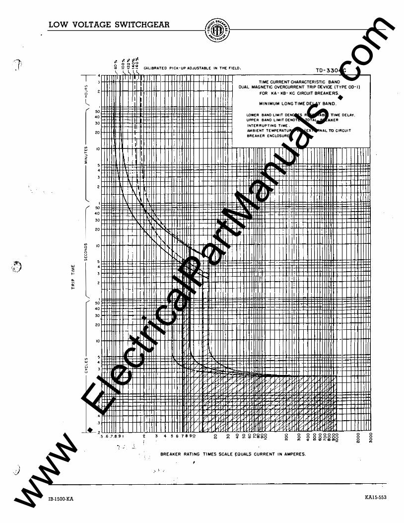
CALIBRATED PICK-UP ADJUSTABLE IN THE FIELD TD-3304C TIME CURRENT CHARACTERISTIC BAND
DUAL MAGNETIC OVERCURRENT TRIP OEVICE (TYPE OD-1)
FOR KA- KB- KC CIRCUIT BREAKERS.
M INIMUM LONG TIME DELAY BAND.
LOWER BAND LIM I T DENOTES RESET TABLE TIME DELAY.
UPPER BAND LIMIT DENOTES TOTAL BREAKER
INTER RUPTI N G TIME.
AMBIENT TEMPERATURE 2:1"\EXTERNAL TO C I RCUI T
BREAI<ER ENCLOSURE l.
\
r, r-...
.... l"o ...
'
'l ' v v vv l/,.tr--- I/,.?
:/ / 1/
7' V,:; / /:7 b', V?
0 2 3 4 5 6 7892 0 0 0 0 � ��g� 0 0 0 0 0 0000
N ..... .. "' 0 0 0 2 o oo·oo 0 "' ,., .. U) ,... tD tnQ 0 "'
BREAKER RATING TIMES SCALE EQUALS CURRENT IN AMPERES.
0 0 0 ,.,
KA15-553 www . El
ectric
alPar
tMan
uals
. com

www . El
ectric
alPar
tMan
uals
. com

KA16-553
LOW VOLTAGE SWITCHGEAR
�;I.��� o 0 0oo "' � !:! � ';t! CALIBRATED PICK-UP ADJUSTABLE lN THE FIELD. TD-3305C
"' a: ::> 0 I
"' w .... " z i
l
4 3
2
I 0 0 0
0
10
5 4 3
2
I ( 50
"' 0 z 0 u w "'
"'
4 3 2
0 0 0
0
5 4 3
2
I 0 0 0
2 0
0
5 w 4 .J u ,_ "
3 2
I .9 ¥ 6 5 4
. 3
- 2
l 'I
I I 1
I
I
I \ 1\ I I -
.. -
-
\ �-
-1-
I
+-.. r---
� l If
, , ' :
-I I I
I
I
Kl I
I I
' ! r-
II' -
I
.5 6 .7.8.91
I I I
I
!I 'I
I I
II t1 -
t l -i't
� �' •u -::tf' ��I ... 1 l !
t I r-..
j
-
I
, , /I
/
I /
'
J v 4 5 6 7 8 92
' ;
....
<: ,/
v
/
/
/
I
!
0 "'
I I ' I
i !
I T j 1
l I i I
/-/
)
TIME CURRENT CHARACTERISTIC B AND DUAL MAGNETIC OVERCURRENT TRIP DEVICE (TYPE 00-1 )
FOR KA- K B - KC CIRCUIT BREAKERS.
INTERMEDIATE LONG TIME DELAY BAND.
LOWER BAND L I MIT DENOTES RESETTABLE TIME DELAY.
UPPER BAND LIMIT DENOTES TOTAL BREAKER
I NTERRUP TING TIME.
AMBI ENT TEMPER ATURE 25"C (EKTERNAL TO CIRCUIT
BREAKER ENCLOSURE).
i
I
11 v..- v,..
v � 7 v v
0 0 0 0 0000 0 :;: � Sol����� 2
BREAKER RATING TIMES SCALE EQUALS CURRENT IN AM PERES.
8 .,
IB-1500-KA
( I,;
www . El
ectric
alPar
tMan
uals
. com

www . El
ectric
alPar
tMan
uals
. com

'� '\) \ ,.'
LOW VOLTAGE SWITCHGEAR
"' "' ::> 0 :z:
l_
I "' "' .... ::> z i
l I
"' 0 z 0 0 ... "' 1&1
l :1! ;:: !!: 0: ...
2
I 50 40 30 20
10
5 4 3 2
I 50 40 30 20
10
2
I 50 40 30 20
10
s 4 3 2
I 9 :¥ .6 .5 ,4 .3
.2
� � � �� a � � � � CALIBRATED PICK·UP ADJUSTABLE IN THE FIELD.
'I' ! I I
. \ ,\
��'r\
� ,, '.
�
'/. � ...; 7 /-
'/. v: 1/. � r/ P': v;
.5 .6 .7.8.9 I 2 3 4 :S 6 7 B 92 0 "'
T0-3306C
TIME CURRENT CHARACTERISTIC BAND DUAL MAGNETIC OVERCURRENT TRIP DEVI C E (TYPE 00· I I
FOR KA·KB·KC CIRCUIT BREAKERS.
MAXIMUM LONG TIME DELAY BAND.
LOWER IIAHD LIMIT DENOTES RESETTA BLE TIME DELAY.
UPPER BAN D LIMIT DENOTES TOTAL BREAKER
INTER RUPTING TIME .
AMBIENT TEMPER ATURE U•C !EXTERN AL TO CI RCUIT
BREAKER ENCLOSURE.)
� ���
� r,.t
bo' ��
i..-'
0 0 0 0 0000 � � s � �g�� 0 0
!il BREAKER RATING TIMES SCALE EQUALS CURRENT IN AMPERES,
I
IB-1500-KA
0 0 0 "'
KA17-553 www . El
ectric
alPar
tMan
uals
. com

www . El
ectric
alPar
tMan
uals
. com


![Business models for the mobile enterprise [g li ntech]](https://static.fdocuments.net/doc/165x107/55ab8cd61a28abac358b456d/business-models-for-the-mobile-enterprise-g-li-ntech.jpg)