
Models 69NT20-284 69NT40-461 69NT40-464 · Carrier Transicold Division, Carrier Corporation, P.O....
120
Models 69NT20-284 69NT40-461 69NT40-464 T-252-05 $6.00
Transcript of Models 69NT20-284 69NT40-461 69NT40-464 · Carrier Transicold Division, Carrier Corporation, P.O....
Models69NT20-28469NT40-46169NT40-464
T-252-05 $6.00

Carrier Transicold Division, Carrier Corporation, P.O. Box 4805, Syracuse, N.Y. 13221
SERVICE MANUALOPERATION AND
Carrier Corporation 1993 D Printed in U. S. A. 0393
CONTAINER REFRIGERATION UNIT
MODELS69NT20-28469NT40-46169NT40-464

i
TABLE OF CONTENTS
Section Page
1 DESCRIPTION 1-1. . . . . . . . . . . . . . . . . . . . . . . . . . . . . . . . . . . . . . . . . . . . . . . . . . . . .1.1 Introduction 1-1. . . . . . . . . . . . . . . . . . . . . . . . . . . . . . . . . . . . . . . . . . . . . . . . . . . . . . . .1.2 General Description 1-2. . . . . . . . . . . . . . . . . . . . . . . . . . . . . . . . . . . . . . . . . . . . . . . . .1.3 Refrigeration System Data 1-8. . . . . . . . . . . . . . . . . . . . . . . . . . . . . . . . . . . . . . . . . . . .1.4 Electrical Data 1-8. . . . . . . . . . . . . . . . . . . . . . . . . . . . . . . . . . . . . . . . . . . . . . . . . . . . . .1.5 Safety Override Thermostat (Optional) 1-9. . . . . . . . . . . . . . . . . . . . . . . . . . . . . . . . .1.6 Voltage Switch And Power Transformer (Optional) 1-9. . . . . . . . . . . . . . . . . . . . . . .1.7 Humidistat (Optional) 1-9. . . . . . . . . . . . . . . . . . . . . . . . . . . . . . . . . . . . . . . . . . . . . . . .1.8 Fresh Air Makeup Vent 1-9. . . . . . . . . . . . . . . . . . . . . . . . . . . . . . . . . . . . . . . . . . . . . . .1.9 Digital Temperature Display 1-10. . . . . . . . . . . . . . . . . . . . . . . . . . . . . . . . . . . . . . . . . . .1.10 Safety And Protective Devices 1-10. . . . . . . . . . . . . . . . . . . . . . . . . . . . . . . . . . . . . . . . .1.11 Refrigeration Circuit 1-11. . . . . . . . . . . . . . . . . . . . . . . . . . . . . . . . . . . . . . . . . . . . . . . . .1.12 Water-Cooled Condenser And Water Pressure Switch (Optional) 1-11. . . . . . . . . . . .1.13 Remote Monitoring Receptacle And Circuit 1-12. . . . . . . . . . . . . . . . . . . . . . . . . . . . .1.14 Suction Solenoid Valve (Model 69NT40) 1-12. . . . . . . . . . . . . . . . . . . . . . . . . . . . . . . .1.15 Frost Formation On Compressors 1-12. . . . . . . . . . . . . . . . . . . . . . . . . . . . . . . . . . . . . .1.16 Controller 1-12. . . . . . . . . . . . . . . . . . . . . . . . . . . . . . . . . . . . . . . . . . . . . . . . . . . . . . . . . .
2 OPERATION 2-1. . . . . . . . . . . . . . . . . . . . . . . . . . . . . . . . . . . . . . . . . . . . . . . . . . . . . . .2.1 Pre-Trip Inspection (Before Starting) 2-1. . . . . . . . . . . . . . . . . . . . . . . . . . . . . . . . . . .2.2 Starting And Stopping Instructions 2-1. . . . . . . . . . . . . . . . . . . . . . . . . . . . . . . . . . . . .2.3 After Starting Inspection 2-2. . . . . . . . . . . . . . . . . . . . . . . . . . . . . . . . . . . . . . . . . . . . . .2.4 Unit Operation 2-2. . . . . . . . . . . . . . . . . . . . . . . . . . . . . . . . . . . . . . . . . . . . . . . . . . . . . .
2.4.1 Cooling --- Controller Set Below ---10_C (+14_F) 2-2. . . . . . . . . . . . . . . .2.4.2 Controller Set Above ---10_C (+14_F) 2-2. . . . . . . . . . . . . . . . . . . . . . . . .2.4.3 Defrost 2-5. . . . . . . . . . . . . . . . . . . . . . . . . . . . . . . . . . . . . . . . . . . . . . . . . . .
3 TROUBLESHOOTING 3-1. . . . . . . . . . . . . . . . . . . . . . . . . . . . . . . . . . . . . . . . . . . . . .3.1 Unit Will Not Start Or Starts Then Stops 3-1. . . . . . . . . . . . . . . . . . . . . . . . . . . . . . . .3.2 Unit Runs But Has Insufficient Cooling 3-1. . . . . . . . . . . . . . . . . . . . . . . . . . . . . . . . .3.3 Unit Operates Long Or Continuously In Cooling 3-1. . . . . . . . . . . . . . . . . . . . . . . . .3.4 Unit Will Not Heat Or Has Insufficient Heating 3-2. . . . . . . . . . . . . . . . . . . . . . . . . .3.5 Unit Will Not Terminate Heating 3-2. . . . . . . . . . . . . . . . . . . . . . . . . . . . . . . . . . . . . . .3.6 Unit Will Not Defrost Properly 3-2. . . . . . . . . . . . . . . . . . . . . . . . . . . . . . . . . . . . . . . .3.7 Abnormal Pressures (Cooling) 3-3. . . . . . . . . . . . . . . . . . . . . . . . . . . . . . . . . . . . . . . . .3.8 Abnormal Noise Or Vibrations 3-3. . . . . . . . . . . . . . . . . . . . . . . . . . . . . . . . . . . . . . . .3.9 Temperature Controller Malfunction 3-3. . . . . . . . . . . . . . . . . . . . . . . . . . . . . . . . . . .3.10 No Evaporator Air Flow Or Restricted Air Flow 3-3. . . . . . . . . . . . . . . . . . . . . . . . . .3.11 Expansion Valve Malfunction 3-4. . . . . . . . . . . . . . . . . . . . . . . . . . . . . . . . . . . . . . . . . .3.12 Water-Cooled Condenser Or Water Pressure Switch Malfunction 3-4. . . . . . . . . . .3.13 Step-Up Power Transformer Malfunction 3-4. . . . . . . . . . . . . . . . . . . . . . . . . . . . . . . .

ii
TABLE OF CONTENTS (CONTINUED)
Section Page
4 SERVICE 4-1. . . . . . . . . . . . . . . . . . . . . . . . . . . . . . . . . . . . . . . . . . . . . . . . . . . . . . . . . .4.1 Removing The Refrigerant 4-1. . . . . . . . . . . . . . . . . . . . . . . . . . . . . . . . . . . . . . . . . . . .4.2 Refrigerant Leak Checking 4-1. . . . . . . . . . . . . . . . . . . . . . . . . . . . . . . . . . . . . . . . . . . .4.3 Evacuation And Dehydration 4-1. . . . . . . . . . . . . . . . . . . . . . . . . . . . . . . . . . . . . . . . . .
4.3.1 General 4-1. . . . . . . . . . . . . . . . . . . . . . . . . . . . . . . . . . . . . . . . . . . . . . . . . . .4.3.2 Preparation 4-1. . . . . . . . . . . . . . . . . . . . . . . . . . . . . . . . . . . . . . . . . . . . . . . .4.3.3 Procedure 4-1. . . . . . . . . . . . . . . . . . . . . . . . . . . . . . . . . . . . . . . . . . . . . . . . . .
4.4 Adding Or Checking The Refrigerant Charge 4-2. . . . . . . . . . . . . . . . . . . . . . . . . . . .4.4.1 Checking The Refrigerant Charge 4-2. . . . . . . . . . . . . . . . . . . . . . . . . . . . .4.4.2 Adding Refrigerant To System (Full Charge) 4-2. . . . . . . . . . . . . . . . . . . .4.4.3 Adding Refrigerant To System (Partial Charge) 4-2. . . . . . . . . . . . . . . . . .
4.5 Replacing The Compressor 4-3. . . . . . . . . . . . . . . . . . . . . . . . . . . . . . . . . . . . . . . . . . .4.6 Compressor Disassembly 4-4. . . . . . . . . . . . . . . . . . . . . . . . . . . . . . . . . . . . . . . . . . . . . .4.7 Compressor Reassembly 4-6. . . . . . . . . . . . . . . . . . . . . . . . . . . . . . . . . . . . . . . . . . . . . .4.8 Checking The Compressor Oil Level 4-7. . . . . . . . . . . . . . . . . . . . . . . . . . . . . . . . . . . .4.9 Checking Or Replacing Moisture-Liquid Indicator 4-8. . . . . . . . . . . . . . . . . . . . . . . .4.10 Checking Or Replacing The Filter-Drier 4-8. . . . . . . . . . . . . . . . . . . . . . . . . . . . . . . .4.11 Checking Or Replacing High Pressure Switch 4-9. . . . . . . . . . . . . . . . . . . . . . . . . . . .
4.11.1 Replacing High Pressure Switch 4-9. . . . . . . . . . . . . . . . . . . . . . . . . . . . . . .4.11.2 Checking High Pressure Switch 4-9. . . . . . . . . . . . . . . . . . . . . . . . . . . . . . . .
4.12 Servicing Quench Solenoid Valve (QV) 4-9. . . . . . . . . . . . . . . . . . . . . . . . . . . . . . . . .4.13 Replacing The Evaporator Coil And Heater Assembly 4-10. . . . . . . . . . . . . . . . . . . . .4.14 Replacing The Evaporator Fan And Motor Assembly 4-10. . . . . . . . . . . . . . . . . . . . . .4.15 Servicing The Evaporator Coil Heaters 4-10. . . . . . . . . . . . . . . . . . . . . . . . . . . . . . . . .4.16 Checking Calibration Of The Defrost Air Switch 4-10. . . . . . . . . . . . . . . . . . . . . . . . .4.17 Condenser Coil 4-11. . . . . . . . . . . . . . . . . . . . . . . . . . . . . . . . . . . . . . . . . . . . . . . . . . . . . .4.18 Condenser Fan And Motor Assembly 4-11. . . . . . . . . . . . . . . . . . . . . . . . . . . . . . . . . . .4.19 Recording Thermometer (Partlow) 4-11. . . . . . . . . . . . . . . . . . . . . . . . . . . . . . . . . . . . .4.20 Recording Thermometer (Saginomiya) 4-13. . . . . . . . . . . . . . . . . . . . . . . . . . . . . . . . . .4.21 Recording Thermometer (Fuji Kiki) 4-14. . . . . . . . . . . . . . . . . . . . . . . . . . . . . . . . . . . .4.22 Rust Prevention And Maintenance Of Painted Surfaces 4-14. . . . . . . . . . . . . . . . . . . .4.23 Servicing The Water-Cooled Condenser 4-14. . . . . . . . . . . . . . . . . . . . . . . . . . . . . . . . .4.24 Checkout Procedure For Optional Power Transformer 4-16. . . . . . . . . . . . . . . . . . . . .4.25 Servicing The Modulating Solenoid Valve 4-16. . . . . . . . . . . . . . . . . . . . . . . . . . . . . . .4.26 Controller Checkout Procedure 4-17. . . . . . . . . . . . . . . . . . . . . . . . . . . . . . . . . . . . . . . .
4.26.1 Controller Pre-Trip 4-17. . . . . . . . . . . . . . . . . . . . . . . . . . . . . . . . . . . . . . . . . .4.26.2 Temperature Control Board Checkout Procedure With TCSM 4-18. . . . .4.26.3 Replacing The Unit Main Control Board 4-19. . . . . . . . . . . . . . . . . . . . . . .4.26.4 Printed Circuit Board Cleaning Procedure 4-19. . . . . . . . . . . . . . . . . . . . . .4.26.5 Temperature Set Station Checkout Procedure 4-19. . . . . . . . . . . . . . . . . . .4.26.6 Temperature Controller Sensor Checkout Procedure 4-20. . . . . . . . . . . . .4.26.7 Replacing Temperature Sensor 4-20. . . . . . . . . . . . . . . . . . . . . . . . . . . . . . . .
4.27 Thermostatic Expansion Valve 4-20. . . . . . . . . . . . . . . . . . . . . . . . . . . . . . . . . . . . . . . . .4.28 Evaporator Fan Motor Capacitors 4-21. . . . . . . . . . . . . . . . . . . . . . . . . . . . . . . . . . . . . .4.29 Humidistat 4-22. . . . . . . . . . . . . . . . . . . . . . . . . . . . . . . . . . . . . . . . . . . . . . . . . . . . . . . . .
5 ELECTRICAL WIRING SCHEMATIC AND DIAGRAMS 5-1. . . . . . . . . . . . . . . . . .5.1 Introduction 5-1. . . . . . . . . . . . . . . . . . . . . . . . . . . . . . . . . . . . . . . . . . . . . . . . . . . . . . . .
iii
LIST OF ILLUSTRATIONS
Figure Page
1-1 Refrigeration Unit --- Front 1-3. . . . . . . . . . . . . . . . . . . . . . . . . . . . . . . . . . . . . . . . . . .1-2 Refrigeration Unit --- Rear (Panels Removed) 1-4. . . . . . . . . . . . . . . . . . . . . . . . . . . .1-3 Water-Cooled Condenser/Receiver Section 1-5. . . . . . . . . . . . . . . . . . . . . . . . . . . . . .1-4 Control Box And Controller (Units With Two-Speed Evaporator Motors) 1-6. . . .1-5 Control Box And Controller (Units With One-Speed Evaporator Motors) 1-7. . . .1-6 Refrigeration Circuit 1-11. . . . . . . . . . . . . . . . . . . . . . . . . . . . . . . . . . . . . . . . . . . . . . . . .1-7 Frost Pattern On Compressors 1-12. . . . . . . . . . . . . . . . . . . . . . . . . . . . . . . . . . . . . . . . .1-8 Current Control Printed Circuit Board 1-13. . . . . . . . . . . . . . . . . . . . . . . . . . . . . . . . . .1-9 Controller Set Point Below ---10_C (+14_F) (Return Air Control) 1-16. . . . . . . . . . .1-10 Controller Set Point Above ---10_C (+14_F) (Supply Air Control) 1-16. . . . . . . . . . .
2-1 Cooling --- Within 2_C (3.6_F) Of Set Point 2-3. . . . . . . . . . . . . . . . . . . . . . . . . . . . . .2-2 Heating --- Within 2_C (3.6_F) Of Set Point 2-4. . . . . . . . . . . . . . . . . . . . . . . . . . . . . .2-3 Defrost 2-5. . . . . . . . . . . . . . . . . . . . . . . . . . . . . . . . . . . . . . . . . . . . . . . . . . . . . . . . . . . .
4-1 Vacuum Pump Connections 4-1. . . . . . . . . . . . . . . . . . . . . . . . . . . . . . . . . . . . . . . . . . .4-2 Compressor --- Model 06DR 4-3. . . . . . . . . . . . . . . . . . . . . . . . . . . . . . . . . . . . . . . . . . .4-3 Oil Pump 4-3. . . . . . . . . . . . . . . . . . . . . . . . . . . . . . . . . . . . . . . . . . . . . . . . . . . . . . . . . . .4-4 Exploded View Of Valve Plate Assembly 4-4. . . . . . . . . . . . . . . . . . . . . . . . . . . . . . . .4-5 Bottom Plate Removed 4-4. . . . . . . . . . . . . . . . . . . . . . . . . . . . . . . . . . . . . . . . . . . . . . .4-6 Vane Oil Pump And Bearing Head 4-5. . . . . . . . . . . . . . . . . . . . . . . . . . . . . . . . . . . . .4-7 Gear Oil Pump And Bearing Head 4-5. . . . . . . . . . . . . . . . . . . . . . . . . . . . . . . . . . . . .4-8 Motor End Cover 4-5. . . . . . . . . . . . . . . . . . . . . . . . . . . . . . . . . . . . . . . . . . . . . . . . . . . .4-9 Crankshaft Assembly 4-6. . . . . . . . . . . . . . . . . . . . . . . . . . . . . . . . . . . . . . . . . . . . . . . .4-10 Removing Equalizing Tube And Lock Screw Assembly 4-6. . . . . . . . . . . . . . . . . . . . .4-11 Terminal Mounting Assembly 4-6. . . . . . . . . . . . . . . . . . . . . . . . . . . . . . . . . . . . . . . . . .4-12 Suction Valve And Positioning Springs In Place 4-7. . . . . . . . . . . . . . . . . . . . . . . . . . .4-13 Piston Rings 4-7. . . . . . . . . . . . . . . . . . . . . . . . . . . . . . . . . . . . . . . . . . . . . . . . . . . . . . . .4-14 Typical Setup For Testing High Pressure Switch 4-9. . . . . . . . . . . . . . . . . . . . . . . . . . .4-15 Evaporator Fan Locating Dimension 4-10. . . . . . . . . . . . . . . . . . . . . . . . . . . . . . . . . . .4-16 Defrost Air Switch Test Set-Up 4-11. . . . . . . . . . . . . . . . . . . . . . . . . . . . . . . . . . . . . . . .4-17 Partlow Recording Thermometer 4-12. . . . . . . . . . . . . . . . . . . . . . . . . . . . . . . . . . . . . .4-18 Saginomiya Recording Thermometer 4-13. . . . . . . . . . . . . . . . . . . . . . . . . . . . . . . . . . .4-19 Fuji Kiki Recording Thermometer 4-14. . . . . . . . . . . . . . . . . . . . . . . . . . . . . . . . . . . . . .4-20 Water-Cooled Condenser Cleaning 4-15. . . . . . . . . . . . . . . . . . . . . . . . . . . . . . . . . . . . .4-21 Modulating Solenoid Valve 4-17. . . . . . . . . . . . . . . . . . . . . . . . . . . . . . . . . . . . . . . . . . . .4-22 Unit Control Board 4-19. . . . . . . . . . . . . . . . . . . . . . . . . . . . . . . . . . . . . . . . . . . . . . . . . .4-23 Temperature Set Station And Plug 4-20. . . . . . . . . . . . . . . . . . . . . . . . . . . . . . . . . . . . .4-24 Sensor 4-20. . . . . . . . . . . . . . . . . . . . . . . . . . . . . . . . . . . . . . . . . . . . . . . . . . . . . . . . . . . . .4-25 Sensor And Cable Assembly 4-20. . . . . . . . . . . . . . . . . . . . . . . . . . . . . . . . . . . . . . . . . . .4-26 Thermostatic Expansion Valve 4-21. . . . . . . . . . . . . . . . . . . . . . . . . . . . . . . . . . . . . . . . .4-27 Humidistat 4-22. . . . . . . . . . . . . . . . . . . . . . . . . . . . . . . . . . . . . . . . . . . . . . . . . . . . . . . . .

iv
LIST OF ILLUSTRATIONS (CONTINUED)Figure Page5-1 Electrical Wiring Schematic (Model 69NT20-284) 5-2. . . . . . . . . . . . . . . . . . . . . . . . .5-2 Electrical Wiring Diagram (Model 69NT20-284) 5-4. . . . . . . . . . . . . . . . . . . . . . . . . .5-3 Electrical Wiring Schematic (Model 69NT40-464) 5-6. . . . . . . . . . . . . . . . . . . . . . . . .5-4 Electrical Wiring Diagram (Model 69NT40-464) 5-8. . . . . . . . . . . . . . . . . . . . . . . . . .5-5 Electrical Wiring Schematic (Model 69NT40-464-1) 5-10. . . . . . . . . . . . . . . . . . . . . . .5-6 Electrical Wiring Diagram (Model 69NT40-464-1) 5-12. . . . . . . . . . . . . . . . . . . . . . . .5-7 Electrical Wiring Schematic (Model 69NT40-464-2) 5-14. . . . . . . . . . . . . . . . . . . . . . .5-8 Electrical Wiring Diagram (Model 69NT40-464-2) 5-16. . . . . . . . . . . . . . . . . . . . . . . .5-9 Electrical Wiring Schematic (Model 69NT40-464-8)
(Units with S/N 90105284 thru 90105383) 5-18. . . . . . . . . . . . . . . . . . . . . . . . . . . . . . . .5-10 Electrical Wiring Diagram (Model 69NT40-464-8)
(Units with S/N 90105284 thru 90105383) 5-20. . . . . . . . . . . . . . . . . . . . . . . . . . . . . . . .5-11 Electrical Wiring Schematic (Model 69NT40-464-8) (Units starting with S/N 90105384) 5-225-12 Electrical Wiring Diagram (Model 69NT40-464-8) (Units starting with S/N 90105384) 5-245-13 Electrical Wiring Schematic (Model 69NT40-464-3) 5-26. . . . . . . . . . . . . . . . . . . . . . .5-14 Electrical Wiring Diagram (Model 69NT40-464-3) 5-28. . . . . . . . . . . . . . . . . . . . . . . .5-15 Electrical Wiring Schematic (Model 69NT20-284-1 & -284-2) 5-30. . . . . . . . . . . . . . .5-16 Electrical Wiring Diagram (Model 69NT20-284-1 & -284-2) 5-32. . . . . . . . . . . . . . . .5-17 Electrical Wiring Schematic (Model 69NT40-464-4) 5-34. . . . . . . . . . . . . . . . . . . . . . .5-18 Electrical Wiring Diagram (Model 69NT40-464-4) 5-36. . . . . . . . . . . . . . . . . . . . . . . .5-19 Electrical Wiring Schematic (Model 69NT40-464-5) 5-38. . . . . . . . . . . . . . . . . . . . . . .5-20 Electrical Wiring Diagram (Model 69NT40-464-5) 5-40. . . . . . . . . . . . . . . . . . . . . . . .5-21 Electrical Wiring Schematic (Model 69NT20-284-3) 5-42. . . . . . . . . . . . . . . . . . . . . . .5-22 Electrical Wiring Diagram (Model 69NT20-284-3) 5-44. . . . . . . . . . . . . . . . . . . . . . . .5-23 Electrical Wiring Schematic (Model 69NT40-464-7 & 69NT40-461-7, -8) 5-46. . . . .5-24 Electrical Wiring Diagram (Model 69NT40-464-7 & 69NT40-461-7, -8) 5-48. . . . . . .5-25 Electrical Wiring Schematic (Model 69NT40-464-9, -15) 5-50. . . . . . . . . . . . . . . . . . .5-26 Electrical Wiring Diagram (Model 69NT40-464-9, -15) 5-52. . . . . . . . . . . . . . . . . . . .5-27 Electrical Wiring Schematic (Model 69NT40-464-10) 5-54. . . . . . . . . . . . . . . . . . . . . .5-28 Electrical Wiring Diagram (Model 69NT40-464-10) 5-56. . . . . . . . . . . . . . . . . . . . . . .5-29 Electrical Wiring Schematic (Model 69NT40-464-12) 5-58. . . . . . . . . . . . . . . . . . . . . .5-30 Electrical Wiring Diagram (Model 69NT40-464-12) 5-60. . . . . . . . . . . . . . . . . . . . . . .
LIST OF TABLESTable Page1-1 Model Chart 1-1. . . . . . . . . . . . . . . . . . . . . . . . . . . . . . . . . . . . . . . . . . . . . . . . . . . . . . . .1-2 Compressor Model Number Significance Chart 1-2. . . . . . . . . . . . . . . . . . . . . . . . . .1-3 Safety And Protective Devices 1-10. . . . . . . . . . . . . . . . . . . . . . . . . . . . . . . . . . . . . . . . .1-4 Current Limiting Switch Positions And Amperages 1-13. . . . . . . . . . . . . . . . . . . . . . .
2-1 Electrical Control Positions --- Above ---10_C (+14_F) 2-6. . . . . . . . . . . . . . . . . . . .2-2 Electrical Control Positions --- Below ---10_C (+14_F) 2-7. . . . . . . . . . . . . . . . . . . . .
4-1 Partlow Bulb Temperature --- Resistance Chart 4-22. . . . . . . . . . . . . . . . . . . . . . . . . . .4-2 Selector Settings And Resistance 4-23. . . . . . . . . . . . . . . . . . . . . . . . . . . . . . . . . . . . . . .4-3 Recommended Bolt Torque Values 4-23. . . . . . . . . . . . . . . . . . . . . . . . . . . . . . . . . . . . .4-4 Wear Limits For Compressors 4-24. . . . . . . . . . . . . . . . . . . . . . . . . . . . . . . . . . . . . . . . .4-5 Compressor Torque Values 4-25. . . . . . . . . . . . . . . . . . . . . . . . . . . . . . . . . . . . . . . . . . . .4-6 Sensor D.C. Voltages 4-25. . . . . . . . . . . . . . . . . . . . . . . . . . . . . . . . . . . . . . . . . . . . . . . . .4-7 Temperature-Pressure Chart --- R-12 4-26. . . . . . . . . . . . . . . . . . . . . . . . . . . . . . . . . . . .

1-1
SECTION 1
DESCRIPTION1.1 INTRODUCTION
This manual contains Operating Data, ElectricalData and Service Instructions for the refrigeration unitslisted in Table 1-1. Also Table 1-1 charts most of thesignificant differences between these models.
The unit, of lightweight aluminum frameconstruction, is an all electric, one piece self-containedcooling and heating refrigeration unit. The unit isdesigned to fit in the front of a container and to serve asthe container front wall. Fork lift pockets are providedfor installation and removal of the unit.
The unit is complete with a charge of Refrigerant-12(These units can be converted to Refrigerant-22. Theelectrical schematic has an R-22 option for CDV, CHT,UV and UVT, these parts can be added to convert theunit to R-22), compressor lubricatingoil, mode indicatinglights, temperature controller and is ready for operationupon installation.
Some units are dual voltage units designed tooperate on 190/230 or 380/460 vac, 3 phase, 50-60 hertzpower. (Refer to Table 1-1 and section 1.6) Other unitsare designed to operate on 380/460 vac, 3 phase 50/60hertz power.
Operating control power is provided by a singlephase transformer which steps down the AC powersupply voltage to 24 vac, 1 phase control power.
The temperature controller is a solid state controller.(Refer to section 1.16) Once the temperature controlleris set at desired container temperature, the unit willoperate automatically to maintain the desiredtemperature within very close limits. The control systemautomatically selects cooling, holding or heating asnecessary to maintain the desired temperature within thecontainer.
The units are equipped with a Partlow dual Simpsonprobe recorder or a Fuji Kiki or Saginomiyabattery-driven recorder.
Also, these units are equipped with a digitaltemperature display (switchable for _C or _F). Refer tosection 1.9.
WARNINGBeware of unannounced starting of theevaporator and condenser fans. Do not opencondenser fan grille before turning power OFFand disconnecting power plug.
Table 1-1. Model Chart
MODELSUNIT WEIGHT
REFRIGER-ANT12
LB KG LB KG
69NT20-284 1330 620 9.0 4.1 X --- --- X X --- ---69NT20-284-1 1170 531 9.0 4.1 --- --- --- --- --- --- ---69NT20-284-2 1160 526 9.0 4.1 --- --- --- --- --- --- ---69NT20-284-3 1285 583 12.3 5.6 --- X --- --- --- X ---69NT40-461-7 1260 571 12.3 5.6 --- --- X --- --- X C69NT40-461-8 1260 572 12.3 5.6 --- --- X --- --- X ---69NT40-464 1200 545 8.8 4.0 --- A --- --- --- X ---69NT40-464-1 1210 560 8.8 4.0 --- A --- --- X X ---69NT40-464-2 1200 545 8.8 4.0 --- A --- --- --- X ---69NT40-464-3 1470 667 12.0 4.4 X X --- X X --- ---69NT40-464-4 1250 567 8.8 3.9 X --- --- X X --- ---69NT40-464-5 1230 558 8.8 4.0 --- A --- --- --- X ---69NT40-464-7 1260 572 12.3 5.58 --- --- X --- --- X C69NT40-464-8 1200 545 8.8 4.0 --- A --- --- --- X ---69NT40-464-9 1240 562 8.8 4.0 --- A --- --- --- X C69NT40-464-10 1230 558 12.3 5.6 --- --- X --- --- --- ---69NT40-464-12 1200 545 8.8 4.0 --- A --- --- --- --- ---69NT40-464-15 1230 558 8.8 4.0 --- A --- --- --- X ---
A --- Provision for water-cooled condenser. If water-cooled condenser is added, refrigerant charge will change.B --- Provision for step-up power transformer.C --- Provision for heat exchanger.X --- Designates item provided.
1-2
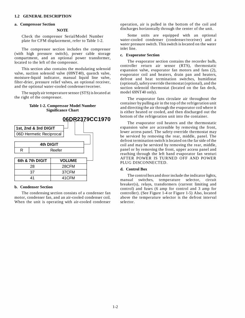
1.2 GENERAL DESCRIPTION
a. Compressor SectionNOTE
Check the compressor Serial/Model Numberplate for CFM displacement, refer to Table 1-2.
The compressor section includes the compressor(with high pressure switch), power cable storagecompartment, and an optional power transformer,located to the left of the compressor.
This section also contains the modulating solenoidvalve, suction solenoid valve (69NT40), quench valve,moisture-liquid indicator, manual liquid line valve,filter-drier, pressure relief valves, an optional receiver,and the optional water-cooled condenser/receiver.
The supply air temperature sensor (STS) is located atthe right of the compressor.
Table 1-2. Compressor Model NumberSignificance Chart
06DR2379CC19701st, 2nd & 3rd DIGIT06D Hermetic Reciprocal
4th DIGITR Reefer
6th & 7th DIGIT VOLUME28 28CFM37 37CFM41 41CFM
b. Condenser SectionThe condensing section consists of a condenser fan
motor, condenser fan, and an air-cooled condenser coil.When the unit is operating with air-cooled condenser
operation, air is pulled in the bottom of the coil anddischarges horizontally through the center of the unit.
Some units are equipped with an optionalwater-cooled condenser (condenser/receiver) and awater pressure switch. This switch is located on the waterinlet line.
c. Evaporator SectionThe evaporator section contains the recorder bulb,
controller return air sensor (RTS), thermostaticexpansion valve, evaporator fan motors and fans (2),evaporator coil and heaters, drain pan and heaters,defrost and heat termination switches, humidistat(optional), safety override thermostat (optional), and thesuction solenoid thermostat (located on the fan deck,model 69NT40 only).
The evaporator fans circulate air throughout thecontainer by pulling air in the top of the refrigeration unitand directing the air through the evaporator coil where itis either heated or cooled, and then discharged out thebottom of the refrigeration unit into the container.
The evaporator coil heaters and the thermostaticexpansion valve are accessible by removing the front,lower access panel. The safety override thermostat maybe serviced by removing the rear, middle, panel. Thedefrost termination switch is located on the far side of thecoil and may be serviced by removing the rear, middle,panel or by removing the front, upper access panel andreaching through the left hand evaporator fan venturiAFTER POWER IS TURNED OFF AND POWERPLUG DISCONNECTED.
d. Control BoxThe controlbox and door include the indicator lights,
manual switches, temperature selector, circuitbreaker(s), relays, transformers (current limiting andcontrol) and fuses (6 amp for control and 3 amp forcontroller). (See Figure 1-4 or Figure 1-5) Also, locatedabove the temperature selector is the defrost intervalselector.

1-3
1. Access Panel (Evaporator Fan Motor #2)2. Access Panel (Heater Location)3. TIR Locking Devices4. Recording Thermometer5. Make-Up Air Cover6. Unit Serial/Model No. Plate --- Location7. Power Cables and Plug8. Power Transformer --- Location9. Discharge Service Valve
10. Compressor Sight Glass
11. High Pressure Switch12. Compressor13. Remote Monitoring Receptacle (RM)14. Manual Defrost Switch15. Start-Stop Switch16. Condenser Fan and Motor17. Fork Lift Pockets18. Thermostatic Expansion Valve --- Location19. Access Panel (Evaporator Fan Motor #1)
1
2
3
4
5
6
7
8
9 10 11 12 13
14
15
16
17
18
19
Figure 1-1. Refrigeration Unit --- Front
1-4
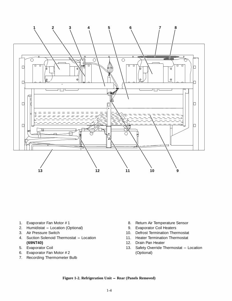
1. Evaporator Fan Motor #12. Humidistat --- Location (Optional)3. Air Pressure Switch4. Suction Solenoid Thermostat --- Location
(69NT40)5. Evaporator Coil6. Evaporator Fan Motor #27. Recording Thermometer Bulb
8. Return Air Temperature Sensor9. Evaporator Coil Heaters
10. Defrost Termination Thermostat11. Heater Termination Thermostat12. Drain Pan Heater13. Safety Override Thermostat --- Location
(Optional)
Figure 1-2. Refrigeration Unit --- Rear (Panels Removed)
1 2 3 4 5 6 7 8
910111213
1-5
12 11
SIDE VIEW
5421
14
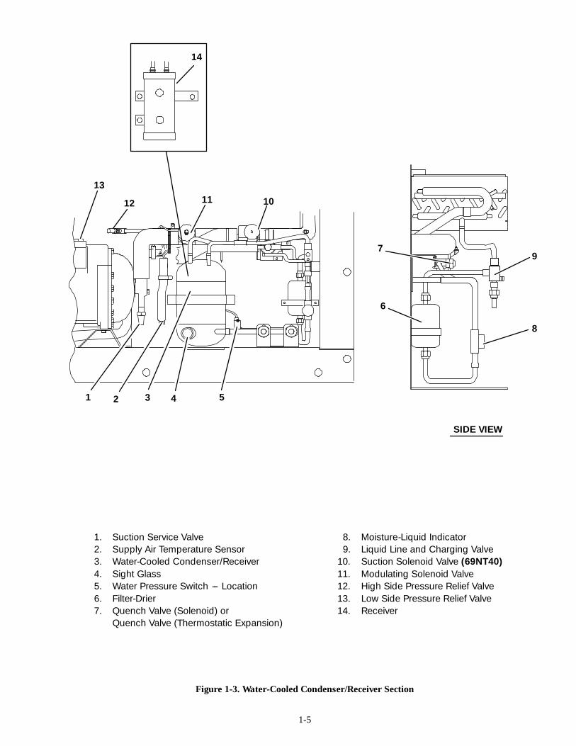
1. Suction Service Valve2. Supply Air Temperature Sensor3. Water-Cooled Condenser/Receiver4. Sight Glass5. Water Pressure Switch --- Location6. Filter-Drier7. Quench Valve (Solenoid) or
Quench Valve (Thermostatic Expansion)
8. Moisture-Liquid Indicator9. Liquid Line and Charging Valve
10. Suction Solenoid Valve (69NT40)11. Modulating Solenoid Valve12. High Side Pressure Relief Valve13. Low Side Pressure Relief Valve14. Receiver
3
Figure 1-3. Water-Cooled Condenser/Receiver Section
13
6
7
8
9
10
1-6
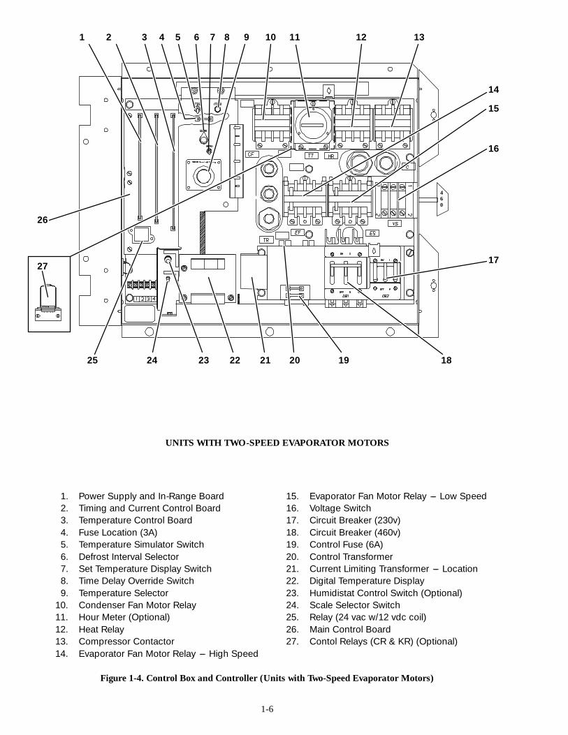
UNITS WITH TWO-SPEED EVAPORATOR MOTORS
1. Power Supply and In-Range Board2. Timing and Current Control Board3. Temperature Control Board4. Fuse Location (3A)5. Temperature Simulator Switch6. Defrost Interval Selector7. Set Temperature Display Switch8. Time Delay Override Switch9. Temperature Selector
10. Condenser Fan Motor Relay11. Hour Meter (Optional)12. Heat Relay13. Compressor Contactor14. Evaporator Fan Motor Relay --- High Speed
15. Evaporator Fan Motor Relay --- Low Speed16. Voltage Switch17. Circuit Breaker (230v)18. Circuit Breaker (460v)19. Control Fuse (6A)20. Control Transformer21. Current Limiting Transformer --- Location22. Digital Temperature Display23. Humidistat Control Switch (Optional)24. Scale Selector Switch25. Relay (24 vac w/12 vdc coil)26. Main Control Board27. Contol Relays (CR & KR) (Optional)
Figure 1-4. Control Box and Controller (Units with Two-Speed Evaporator Motors)
460
1 2 3 4 5 9 10
17
181920212225
26
7 12 13
14
16
6 8 11
15
2324
27

1-7
UNITS WITH ONE-SPEED EVAPORATOR MOTORS
1. Power Supply and In-Range Board2. Timing and Current Control Board3. Temperature Control Board4. Fuse Location (3A)5. Temperature Simulator Switch6. Defrost Interval Selector7. Time Delay Override Switch8. Set Temperature Display Switch9. Temperature Selector
10. Condenser Fan Motor Relay11. Evaporator Fan Motor Relay12. Heat Relay
13. Compressor Contactor14. Voltage Switch15. Circuit Breaker (230v)16. Circuit Breaker (460v)17. Control Fuse (6A)18. Control Transformer --- Location19. Current Limiting Transformer20. Digital Temperature Display21. Scale Selector Switch22. Relay (24 vac w/12 vdc coil)23. Main Control Board
Figure 1-5. Control Box and Controller (Units with One-Speed Evaporator Motors)
1 2 3 4 5 6 7 8 9 10 11 12 13
14
15
16171819202122
23
1-8
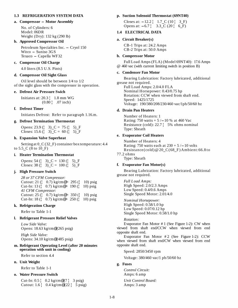
1.3 REFRIGERATION SYSTEM DATAa. Compressor --- Motor Assembly
No. of Cylinders: 6Model: 06DRWeight (Dry): 132 kg (290 lb)
b. Approved Compressor OilPetroleum Specialties Inc. --- Cryol 150Witco --- Suniso 3GSTexaco --- Capella WF32
c. Compressor Oil Charge4.0 liters (8.5 U.S. Pints)
d. Compressor Oil Sight GlassOil level should be between 1/4 to 1/2
of the sight glass with the compressor in operation.
e. Defrost Air Pressure Swich
Initiates at: 20.3 ¦ 1.8 mm WG(0.80 ¦ .07 inch)
f. Defrost TimerInitiates Defrost: Refer to paragraph 1.16.m.
g. Defrost Termination ThermostatOpens: 23.9 (¦ 3)_C = 75 (¦ 5)_FCloses: 15.6 (¦ 3)_C = 60 (¦ 5)_F
h. Expansion Valve SuperheatSettingat 0_C (32_F) container box temperature: 4.4
to 5.5_C (8 to 10_F)
i. Heater Termination ThermostatOpens: 54 (¦ 3)_C = 130 (¦ 5)_FCloses: 38 (¦ 3)_C = 100 (¦ 5)_F
j. High Pressure Switch28 or 37 CFM Compressor:Cutout: 21 (¦ 0.7) kg/cm@ = 295 (¦ 10) psigCut-In: 13 (¦ 0.7) kg/cm@ = 190 (¦ 10) psig41 CFM Compressor:Cutout: 25 (¦ 0.7) kg/cm@ = 350 (¦ 10) psigCut-In: 18 (¦ 0.7) kg/cm@ = 250 (¦ 10) psig
k. Refrigeration ChargeRefer to Table 1-1
l. Refrigerant Pressure Relief ValvesLow Side Valve:Opens: 18.63 kg/cm@ (265 psig)
High Side Valve:Opens: 34.10 kg/cm@ (485 psig)
m. Refrigerant Operating Level (after 20 minutesoperation with unit in cooling)Refer to section 4.4
n. Unit WeightRefer to Table 1-1
o. Water Pressure SwitchCut-In: 0.5 ¦ 0.2 kg/cm@ (7 ¦ 3 psig)Cutout: 1.6 ¦ 0.4 kg/cm@ (22 ¦ 5 psig)
p. Suction Solenoid Thermostat (69NT40)Closes at: ---12.2 ¦ 1.7_C (10 ¦ 3_F)Opens at: ---6.7 ¦ 3.3_C (20 ¦ 6_F)
1.4 ELECTRICAL DATA
a. Circuit Breaker(s)CB-1 Trips at: 24.2 AmpsCB-2 Trips at: 50.0 Amps
b. Compressor MotorFull Load Amps (FLA) (Model 69NT40): 17.6 Amps
@ 460 vac (with current limiting switch in position B)
c. Condenser Fan MotorBearing Lubrication: Factory lubricated, additional
grease not required.Full Load Amps: 2.0/4.0 FLANominal Horsepower: 0.43/0.75 hpRotation: CCW when viewed from shaft end.Speed: 1425/1725Voltage: 190/380/208/230/460 vac/1ph/50/60 hz
d. Drain Pan HeatersNumber of Heaters: 1Rating: 750 watts +5 /---10 % at 460 VacResistance (cold): 22.7 ¦ 5% ohms nominalType: Sheath
e. Evaporator Coil HeatersNumber of Heaters: 4Rating: 750 watts each at 230 +5 /---10 voltsResistance(cold)@20_C(68_F)Ambient:66.8 to
77.2 ohmsType: Sheath
f. Evaporator Fan Motor(s)Bearing Lubrication: Factory lubricated, additional
grease not required.
Full Load Amps:High Speed: 2.0/2.3 AmpsLow Speed: 0.4/0.6 AmpsSingle Speed Motor: 2.01/4.0
Nominal Horsepower:High Speed: 0.58/1.0 hpLow Speed: 0.07/0.12 hpSingle Speed Motor: 0.58/1.0 hp
Rotation:Evaporator Fan Motor #1 (See Figure 1-2): CW when
viewed from shaft end/CCW when viewed from endopposite shaft end.
Evaporator Fan Motor #2 (See Figure 1-2): CCWwhen viewed from shaft end/CW when viewed from endopposite shaft end.
Speed: 2850/3450 rpm
Voltage: 380/460 vac/1 ph/50/60 hz
g. FusesControl Circuit:Amps: 6 amp
Unit Control Board:Amps: 3 amp
1-9
1.5 SAFETY OVERRIDE THERMOSTAT(OPTIONAL)
This thermostat is fixed at ---3.9_C (25_F) to providea low temperature limit on the evaporator supply air(discharge air) when transporting perishablecommodities.
When the temperature controller is set below ---10_C(14_F), the safety override thermostat is bypassed asrelay TU is de-energized and contacts T36 to T35 areclosed, refer to section 5.
For thermostat location see Figure 1-2.1.6 VOLTAGE SWITCH AND POWER
TRANSFORMER (OPTIONAL)
WARNINGDo not attempt to remove power plug(s) beforeturning OFF start-stop switch (ST), unit circuitbreaker(S) and external power source. Make surethe power plugs are clean and dry beforeconnecting to any power receptacle.
a. Step-Up Power Transformer
The transformer is located under the condenser coil(left-hand side of unit) and the purpose of thistransformer is to provide 380 vac/3 ph/50 hz power whenthe 190/230 vac power cable (black) is connected to a 190vac power supply or to provide 460 vac/3 ph/60 hz whenthe 190/230 vac power cable (black) is connected to a 230vac power supply.
WARNINGDo not attempt to remove power plug beforeturning OFF voltage switch (VS), start-stopswitch (ST), unit circuit breakers (CB-1 AndCB-2), and external power source.
b. To Place Unit on 190/230 vac Power Supply
1. Make sure voltage switch (VS) is in the OFFposition. Make sure start-stop switch (ST, on controlpanel) and circuit breakers CB-2 is in position “O”(OFF). (See Figure 1-4 or Figure 1-5)
2. Connect 190/230 vac power cable plug (blackcable). Place voltage switch (VS) in the 230 v position.Place circuit breaker (CB-2) in position “1”. Close andsecure control box door and then place the start-stopswitch (ST) in position “1”.c. To Place Unit on 380/460 vac Power Supply
1. Make sure voltage switch (VS) is in the OFFposition. Make sure start-stop switch (ST, on controlpanel) and circuit breaker (CB-1) is in position “O”.(OFF).
2. Connect 380/460 vac power cable plug (yellowcable). Place voltage switch (VS) in the 460 v position.Place circuit breaker (CB-1) in position “1”. Close andsecure control box door and then place the start-stopswitch (ST) in position “1”.1.7 HUMIDISTAT (OPTIONAL)
NOTEThe supply air must be in-range or humidistatcircuit will not energize.
The humidistat (Figure 1-2) is factory set at 70%relative humidity (R.H.) and is designed to operate whentransporting a chill load (controller set above ---10_C(14_F) and is locked out when the controller is set below---10_C (TU contacts T35 to T37 are open).a. The humidistat will be in operation if:
1. Supply air is in-range (in-range light illuminated).
2. Humidistat control switch in the ON position.
3. Controller is set above ---10_C (14_F).
4. Container relative humidity reaches the 70%R.H. setting of humidistat.
The above energizes the humidistat circuit as relayIRS contacts T24 to T23, TU relay contacts T35 to T37,HCS contacts 1-2, and HC contacts 1-3 close to energizethe heaters and heat light.b. For testing purposes:
WARNINGBeware of rotating evaporator fan whenconducting following test.
1. Remove the front evaporator fan motor #1access panel (see Figure 1-1). The humidistat is locatedbehind this panel.
2. Move the controller set pointer within 2_C(3.6_F) of container supply air temperature.
3. Move the humidistat control switch to ONposition (position 1).
4. Turn the humidistat control knob until heatersare energized (heat light ON) and then reset control to70% R.H. Replace access panel and lockwire.1.8 FRESH AIR MAKEUP VENT
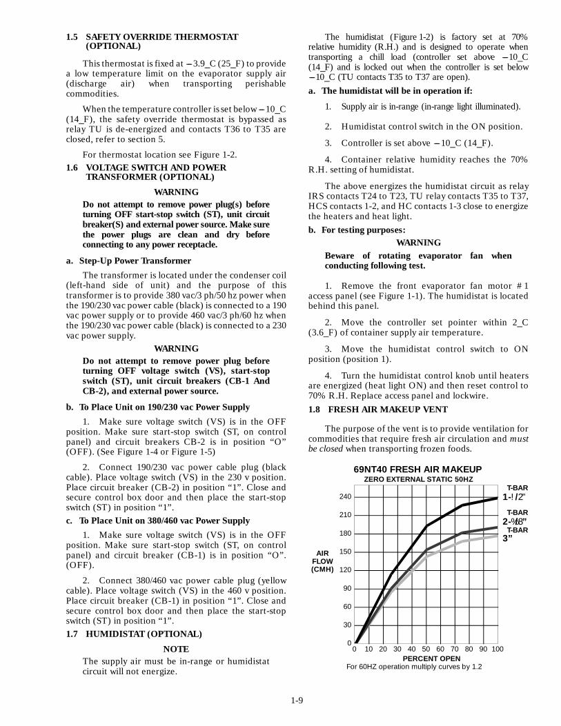
The purpose of the vent is to provide ventilation forcommodities that require fresh air circulation and mustbe closed when transporting frozen foods.
0
30
60
90
120
150
180
210
240
0 10 20 30 40 50 60 70 80 90 100
AIRFLOW(CMH)
1-!/2”
PERCENT OPEN
69NT40 FRESH AIR MAKEUP
T-BAR
2-%/8”
3”T-BAR
T-BAR
ZERO EXTERNAL STATIC 50HZ
For 60HZ operation multiply curves by 1.2
1-10
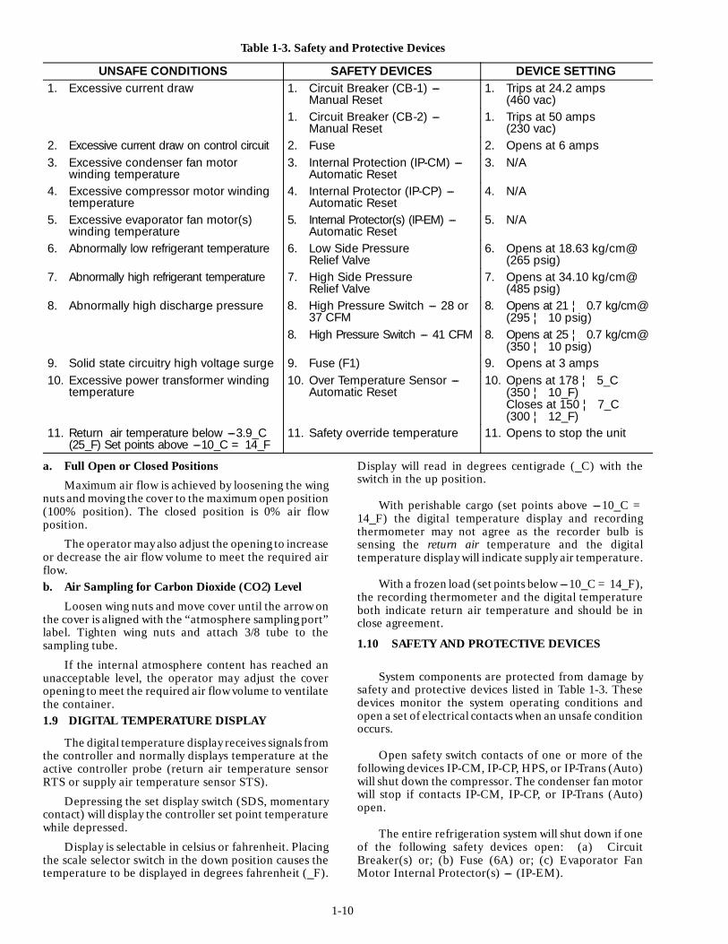
Table 1-3. Safety and Protective Devices
UNSAFE CONDITIONS SAFETY DEVICES DEVICE SETTING1. Excessive current draw 1. Circuit Breaker (CB-1) ---
Manual Reset1. Trips at 24.2 amps
(460 vac)1. Circuit Breaker (CB-2) ---
Manual Reset1. Trips at 50 amps
(230 vac)2. Excessive current draw on control circuit 2. Fuse 2. Opens at 6 amps3. Excessive condenser fan motor
winding temperature3. Internal Protection (IP-CM) ---
Automatic Reset3. N/A
4. Excessive compressor motor windingtemperature
4. Internal Protector (IP-CP) ---Automatic Reset
4. N/A
5. Excessive evaporator fan motor(s)winding temperature
5. Internal Protector(s) (IP-EM) ---Automatic Reset
5. N/A
6. Abnormally low refrigerant temperature 6. Low Side PressureRelief Valve
6. Opens at 18.63 kg/cm@(265 psig)
7. Abnormally high refrigerant temperature 7. High Side PressureRelief Valve
7. Opens at 34.10 kg/cm@(485 psig)
8. Abnormally high discharge pressure 8. High Pressure Switch --- 28 or37 CFM
8. Opens at 21 ¦ 0.7 kg/cm@(295 ¦ 10 psig)
8. High Pressure Switch --- 41 CFM 8. Opens at 25 ¦ 0.7 kg/cm@(350 ¦ 10 psig)
9. Solid state circuitry high voltage surge 9. Fuse (F1) 9. Opens at 3 amps10. Excessive power transformer winding
temperature10. Over Temperature Sensor ---
Automatic Reset10. Opens at 178 ¦ 5_C
(350 ¦ 10_F)Closes at 150 ¦ 7_C(300 ¦ 12_F)
11. Return air temperature below ---3.9_C(25_F) Set points above ---10_C = 14_F
11. Safety override temperature 11. Opens to stop the unit
a. Full Open or Closed Positions
Maximum air flow is achieved by loosening the wingnuts and moving the cover to the maximum open position(100% position). The closed position is 0% air flowposition.
The operator may also adjust the opening to increaseor decrease the air flow volume to meet the required airflow.b. Air Sampling for Carbon Dioxide (CO2) Level
Loosen wing nuts and move cover until the arrow onthe cover is aligned with the “atmosphere sampling port”label. Tighten wing nuts and attach 3/8 tube to thesampling tube.
If the internal atmosphere content has reached anunacceptable level, the operator may adjust the coveropening to meet the required air flow volume to ventilatethe container.1.9 DIGITAL TEMPERATURE DISPLAY
The digital temperature display receives signals fromthe controller and normally displays temperature at theactive controller probe (return air temperature sensorRTS or supply air temperature sensor STS).
Depressing the set display switch (SDS, momentarycontact) will display the controller set point temperaturewhile depressed.
Display is selectable in celsius or fahrenheit. Placingthe scale selector switch in the down position causes thetemperature to be displayed in degrees fahrenheit (_F).
Display will read in degrees centigrade (_C) with theswitch in the up position.
With perishable cargo (set points above ---10_C =14_F) the digital temperature display and recordingthermometer may not agree as the recorder bulb issensing the return air temperature and the digitaltemperature display will indicate supply air temperature.
With a frozen load (set points below ---10_C = 14_F),the recording thermometer and the digital temperatureboth indicate return air temperature and should be inclose agreement.
1.10 SAFETY AND PROTECTIVE DEVICES
System components are protected from damage bysafety and protective devices listed in Table 1-3. Thesedevices monitor the system operating conditions andopen a set of electrical contacts when an unsafe conditionoccurs.
Open safety switch contacts of one or more of thefollowing devices IP-CM, IP-CP, HPS, or IP-Trans (Auto)will shut down the compressor. The condenser fan motorwill stop if contacts IP-CM, IP-CP, or IP-Trans (Auto)open.
The entire refrigeration system will shut down if oneof the following safety devices open: (a) CircuitBreaker(s) or; (b) Fuse (6A) or; (c) Evaporator FanMotor Internal Protector(s) --- (IP-EM).

1-11
1.11 REFRIGERATION CIRCUITStarting at the compressor (see Figure 1-6), the
suction gas is compressed to a higher temperature andpressure.
1. Suction Service Valve2. Discharge Service Valve3. Air-Cooled Condenser4. Water-Cooled Condenser or Receiver5. Sight Glass6. Water Outlet7. Water Inlet8. Pressure Relief Valve (High Side)9. Pressure Relief Valve (Low Side)
10. Liquid Line Valve11. Filter-Drier12. Moisture-Liquid Indicator13. Expansion Valve14. External Equalizer Line15. Expansion Valve Bulb16. Evaporator17. Suction Solenoid Valve (69NT40)18. Modulating Solenoid Valve19. Quench Valve (Solenoid or Thermostatic)
18
2
16
8
71
3
4
10
5 6
9
11
13
14
15
17
19
12
Figure 1-6. Refrigeration Circuit
When operating with the air-cooled condenser, thegas flows through the discharge service valve into theair-cooled condenser. Air flowing across the coil fins andtubes cools the gas to saturation temperature. Byremoving latent heat, the gas condenses to a hot liquidand then flows to the water-cooled condenser/receiverwhich stores the additional charge necessary for lowtemperature operation.
When operating with the water-cooled condenser, thehot gas flows through the air-cooled condenser and intothe water-cooled condenser. The heat flows from the hotgas into the condenser coolant thus cooling thecompressed gas and changing the state of refrigerantfrom a gas to a liquid.
From the condenser/receiver, the liquid refrigerantflows by a pressure relief valve which opens if therefrigerant pressure is abnormally high.
The liquid refrigerant continues through a liquid lineshutoff valve, filter-drier (which keeps refrigerant cleanand dry), a moisture-liquid indicator and then to thethermostatic expansion valve. As the liquid refrigerantpasses through the orifice of the expansion valve some ofit vaporizes into a gas (flash gas). Heat is absorbed fromthe evaporator air by the balance of the liquid causing itto vaporize in the evaporator coil. The vapor then flowsthrough the suction line to the compressor.
The thermostatic expansion valve bulbon the suctionline near the evaporator coil outlet, controls the valve,maintaining a relatively constant superheat at the coiloutlet regardless of load conditions except at abnormallyhigh container temperatures such as during pulldown(valve at maximum operating pressure condition).
1.12 WATER-COOLED CONDENSER ANDWATER PRESSURE SWITCH(OPTIONAL)
The water-cooled condenser is used when heatingthe surrounding air is objectionable such as in a ship’shold and cooling water is available.
The water-cooled condenser is of the shell and coiltype with circulating water through the cupro-nickel coil.The refrigerant vapor is admitted to the shell side and iscondensed on the outer surface of the coil.
For operation of the refrigeration unit with the water-cooledcondenser, do the following:
a. Connect water supply line to inlet side ofcondenser and discharge line to outlet side of condenser.
b. Maintain a flow rate of 11 to 26 litres (3 to 7 U.S.gallons) per minute. The water pressure switch will opento de-energize the condenser fan relay. The condenserfan motor will stop and will remain stopped until thewater pressure switch closes.
The refrigeration unit operating with thewater-cooled condenser will perform as outlined insection 2.4 except that the condenser fan motor isstopped in all modes.
To shift to air-cooled condenser operation, do the following:
Disconnect the water supply and the discharge line tothe water-cooled condenser. The refrigeration unit willshift to air-cooled condenser operation when the waterpressure switch closes. (Refer to paragraph 1.3.o.)

1-12
1.13 REMOTE MONITORING RECEPTACLEAND CIRCUIT
When the remote monitor is connected to theremote monitoring receptacle, Figure 1-1, the followingremote circuits are energized.
Circuit Function
Sockets B to A Energizes remote cool lightSockets C to A Energizes remote defrost lightSockets D to A Energizes remote in-range light
NoteThe in-range light will be illuminated if thecontainer return air temperature is within 2_C(3.6_F). Refer to paragraph 1.16.n.
1.14 SUCTION SOLENOID VALVE(Model 69NT40)
The suction solenoid valve, shown in Figure 1-3 iscontrolled by the suction solenoid thermostat (located onthe evaporator fan motor deck as shown in Figure 1-2).
In operation, if the return air temperature decreasesto ---12.2_C (10_F), the suction solenoid thermostat(SST) closes to energize the suction solenoid valve, whichopens to increase the refrigerant flow rate and coolingcapacity.
The thermostat opens with increasing return airtemperature at ---7 ¦ 3_C (20 ¦ 6_F) to de-energize thevalve.
1.15 FROST FORMATION ON COMPRESSORS
NoteSome models have a thermostatic expansionquench valve, so frost formation on thecompressor is not applicable. To see whichmodels use a solenoid quench valve refer tosection 5.
Frost may, in normal operation, form on thecompressor suction service valve and end bell. This iscaused by normal quench valve operation in conjunctionwith the suction modulation valve. Figure 1-7A shows theallowable frost limit pattern for units operating with thecontroller set point above ---10_C (14_F). This frostpattern is described below.
The temperature controller varies the amount ofcurrent through the suction modulation valve coil whichin turn increases or decreases the amount of restriction inthe suction line, so that the net cooling capacity of theunit will match the cooling required to maintain the loadat set point.
When the suction modulation valve is approximately50% closed (approximately 0.6 amps output to thesuction modulation valve coil from the temperaturecontroller), the temperature controller will energize thequench solenoid valve. When the quench valve is opened,a small amount of liquid refrigerant is metered throughan orifice (which acts as an expansion device) into the
suction line down streamof the suction modulation valve.Because of low compressor suction pressures created bythe suction modulation valve, the liquid fed by thequench valve flashes to a low temperature gas and,therefore, the compressor may form frost or ice on theend bell and top of the motor cavity adjacent to thesuction gas path of flow. This is not harmful to thecompressor, as the restrictor in the quench valve lineprevents excessive liquid from flowing into thecompressor.
Figure AController Set Above --10_C (14_F)
Figure BController Set Below --10_C (14_F)
Figure 1-7. Frost Pattern on Compressors
With the controller set below ---10_C (14_F) theallowable compressor frost pattern limit is shown inFigure 1-7B. The frost line will not normally extendbeyond the suction service valve as the quench valveshould not energize when operating with the controllerset point below ---10_C (14_F).
If excessive frost is noticed on the compressor andthe suction modulation system is operating normally,then the thermal expansion valve superheat settingshould be checked. Flooding by a thermal expansionvalve may cause oil to foam excessively. Normal quenchvalve operation will not foam the oil significantly afteroperation has stabilized.
Adhesive-backed labels depicting allowable frostpatterns on compressors are available from CarrierTransicold Replacement Component Group.
1.16 CONTROLLER
h. General Description (See Figure 1-4 or Figure 1-5)
The Carrier Transicold controller is a modularassembly of solid state electronic circuits that combines anumber of refrigeration system control functions in asingle unit.

1-13
The functions are: (1) temperature control; (2)current control; (3) temperature control function timedelays; (4) selectable time interval defrost; and, (5)out-of-range indication time delay.
The controller consists of a programmed main circuitboard, three plug-in control circuit boards, five or sixplug-in relays, and remote located components whichare: (1) temperature set point potentiometer; (2) twotemperature sensing probes; (3) two switches forchecking calibration; and, (4) current limitingtransformer.
The controller has high precision components incritical circuits which result in the elimination ofcalibration adjustments. As long as componentreplacements are made using factory specified parts,calibration will be maintained.
i. Model 69NT40 Current Control(Capacity Override)
The current control function of the controller limitsthe maximum unit current draw to prevent possibleoverloading of limited power sources such as anengine-generator set when operating with high containertemperatures and high ambient temperatures. Refer toTable 1-4.
The current control function, when required, willoverride the normal modulated capacity control function(described in paragraph 1.16.j.) to reduce coolingcapacity sufficiently to prevent total unit current fromexceeding a preset value. This is accomplished bycircuitry on the timing and current control circuit boardin response to the current sensed in one phase of thecompressor power line by current limiting transformer(CLT). The current limit on the timing and currentcontrol board is factory set in switch position “B” (seeFigure 1-8).
A
B CD
ESW1
CURRENT LIMIT SWITCH
Figure 1-8. Current Control Printed Circuit Board
Table 1-4. Current Limiting Switch Positions andAmperages
Switch Position A B C D E460 vac Operation 15A 17A 19A 21A 23A230 vac Operation 30A 34A 38A 42A 46A
NOTES1. If the current limiting switch is set too low,unit pulldown capacity may be reduced due tolimitation of compressor amperage asdetermined by the timing and current controlboard.
2. Table 1-4 shows the approximate total unitamps for each position of the current limitcontrol.
j. Temperature Control (Capacity Control)The temperature control portion of the controller
consists of a temperature set point potentiometer (CSS),return air (RTS) and supply air (STS) temperaturesensors (two thermistor probes), solid state circuitry(temperature control, timing and current control, powersupply and IRS printed circuit boards), and associatedcontrol relays. Each temperature sensor is located in itsrespective air stream.
Operation at any desired temperature within the setpoint range (---25_C to +25_C or ---15_F to +80_F) isachieved by turning the set point potentiometer knob toposition the pointer at the desired temperature.
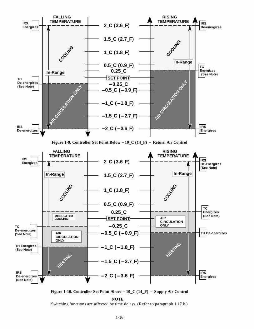
A change in sensed air temperature (supply or returnair depending on set point) causes a correspondingchange in electrical resistance of the thermistor sensor.This change is processed by the electronic circuitry of thecontroller which actuates control relays and therefrigerant suction modulating valve in accordance withthe controller operating diagrams as shown in NO TAGand NO TAG.
For set points above ---10_C (14_F) relay TU will beenergized along with contactor EF. The two-speedevaporator motors will be in high speed.
Also, for set points above ---10_C (14_F), thecontroller will maintain supply air at the set temperatureby the following modes of operation:
1. Conventional, Humidity Control Switch (HCS)in position “O” --- cooling by refrigeration with suctionmodulation and the compressor cycling at light loads.Electric resistance heating.
2. Conventional plus Dehumidification, HumidityControl Switch in position “1” --- cooling by refrigerationwith suction modulation and compressor cycling at lowhumidities, suction modulation and simultaneouselectric resistance heating at high humidities.
1. Operation in the Conventional ModeOperation in the Conventional Mode (HCS in
position “O”) with the set point setting below the airtemperature at the supply air probe but above ---10_C(14_F) the unit starts in cooling with controller relays TUand TQ energized. Compressor and condenser fancontactors are energized through relay TC contacts T9and T3 (now closed) and relay TQ contacts T7 to T6 (nowclosed).
As the sensed temperature continues to fall, themodulating valve current will remain at minimum (under0.2 amp) until the sensed temperature drops to 0.25_C(0.45_F) above set point.
1-14
With any further drop in sensed temperature,modulated (continuously variable) capacity reductionoccurs to match cooling requirements that are less thanthe maximum capacity of the unit. This permits exactbalancing of unit capacity with a wide range of coolingloads while maintaining continuous compressoroperation and holding the temperature very close to setpoint. This variable cooling capacity is achieved by amodulating solenoid valve which provides a variablerestriction in the compressor suction line. This valvevaries the flow rate of the refrigerant pumped by thecompressor.
For low cooling capacity operation requiring higherthan 0.62 amp modulating valve current, the two-wayquench solenoid valve is energized (opened) whichallows a small, metered flow of liquid refrigerant to enterthe suction line and provide supplemental compressormotor cooling.
For very small cooling requirements that are lessthan the minimum refrigeration capacity of the unit (fullyclosed modulating valve), the controller will cyclecompressor on and off to match the load.De-energization of relay TC to stop the compressor isdelayed to prevent nuisance cycling from brief lowtemperature swings. Once off, the compressor will notrestart for 5 to 6 minutes. (Refer to paragraph k.)
In cold ambients when container heating is required,the sensed temperature will drop to 1.0_C (1.8_F) belowset point and the controller will cycle electric resistanceheating with a transient masking delay on energizationsimilar to that associated with compressor cycling. Theheat relay (contactor HR) is energized through the closedcontacts (N.C.) of relay TC by controller relay THenergizing and closing the TH contacts (N.O.). Heatrelay (contactor) HR energizes the defrost and drain panheaters.
For set points below ---10_C (14_F), return airtemperature is sensed and the range of capacityreduction is more limited than for higher set points.When cooling requirements are less than the minimumcontinuous operatingcapacity of the unit, the unit revertsto on-off compressor cycling to match the load. Whencooling, compressor and condenser fan contactors areenergized through the normally open (N.O.) contacts ofrelay TC.
Also, for set points below ---10_C (14_F), thecontroller will maintain return air at the set temperatureby refrigeration. Electric resistance heating iselectronically locked out in this temperature range. Unitswith two-speed evaporator fan motors will have theevaporator fan motors in low speed as relay TU will bede-energized. (Contactor ES energized.)
Electric resistance heating is locked out for set pointsbelow ---10_C (14_F) by controller relay TH being lockedout to prevent energizing the circuit.
Cargo temperatures will necessarily vary somewhatfrom controlled air temperatures. A simple numericaldifference between product temperature and controlledair temperature cannot be stated because of the complex
relationship of air flow variations within the containerand temperature gradients of air and product. However,during cooling, it can be stated that with supply aircontrol, a minimum product temperature will beeffectively maintained and with return air control, amaximum product temperature will be effectivelymaintained.
2. Operation in the Dehumidification ModeOperation in the Dehumidification Mode (HCS in
position “1”). With the set point setting below the airtemperature at the supply air probe (but above ---10_C(14_F) starts with controller relays TU and TQenergized. The compressor and condenser fan contactorsare energized through normally closed TC relay contacts.The evaporator fan motors are as previously described.
Cooling capacity reduction by modulation is thesame as described for the conventional operating modewhen the return air relative humidity is below the settingon the humidity controller (HC) and as long as anout-of-range temperature condition exists, regardless ofreturn air relative humidity.
For relative humidities higher than the HC setting, ifthe supply air temperature drops to 2_C (3.6_F) aboveset point, in-range relay (IRS) energizes and, in turn,energizes heat relay (contactor) HR thorough closed(N.O.) relay HC contacts. Also, the in-range and heatlights are illuminated at this time.
This applies power to the defrost and drain panheaters. This added head load causes the controller toopen the modulating valve to match the new total heatload while still holding the supply air temperature veryclose to set point.
Opening the modulating valve reduces thetemperature of the evaporator coil surface whichincreases the rate water is condensed from the air passingthrough the coil. Removing water from the air reducesthe relative humidity until the HC setting is reached andcontroller HC contacts open to de-energize heating.
Humidity controller HC will continue to cycleheating to maintain relative humidity below HC setting.
With set points below ---10_C (14_F), operation isthe same as previously described for conventional mode--- heating and dehumidification are locked out.
k. Time DelaysTC relay operation is affected by a time delay
function of the Timing and Current Control Board; itspurpose is to prevent short cycling of the compressor.
To prevent short cycling of the compressor, a sixminute compressor off time must be satisfied. When thetimer completes its six minute cycle, the followingtemperature requirements must be met to allow thecompressor to start.
1. ¦ .25_C (¦ .45_F) from setpoint, setpointsabove ---10_C (14_F).
2. ¦ .50_C (¦ .9_F) fromsetpoint, setpoints below---10_C (14_F).
Until these temperature requirements are met, thetimer will continue to cycle.

1-15
Additional transient override time delays affect theoperation of TC and TH relays. These delays are alloverridden by pressing the time delay override switch(TDS).l. Lockout Functions
Heating function lockout for set points below ---10_C(14_F) is achieved by relay TH being prevented fromenergizing.m. Selectable Time Interval Defrost
A selectable interval defrost initiation timer isincluded in the timing and current control board. Thetime interval between defrost initiations (90 second test,3 hours, 6 hours, 12 hours, or 24 hours) is set with thedefrost interval selector switch (DIS).
The controller initiates defrost (providing theevaporator coil temperature is below 13_C = 55_Frequired to close the defrost termination thermostatcontacts) by:1. Energizing defrost relay (DR) energizes the defrostlight and stops the evaporator fan motors byde-energizing the evaporator fan motor contactor.2. De-energizing cooling relay (TC) and energizing andheating relay (TH). This stops the compressor andcondenser fan motor and energizes the defrost and drainpan heaters.
Defrosting is terminated by the defrost terminationthermostat (DTT), which opens when the evaporator coiltemperature rises to 24_C (75_F) after all frost has beenmelted from the coil.
Also, defrost may be manually initiated at any timeby actuating the manual defrost switch (MDS).
NOTEDefrost interval timing restarts at time zerowhenever the time delay override switch (TDS)is depressed or control circuit power is restoredafter an interruption such as occurs whenstopping or starting unit (ST switch).
n. Out-of-Range Indication Time DelayDuring defrost, the temperature at the sensingprobe
rises above the upper in-range limit which would result inan out-of-range indication if the temporary conditionwere not overridden. Circuitry on the timing and currentcontrol board works in conjunction with the temperaturecontrol circuitry to delay de-energization of the in-rangerelay (IRS) until approximately 90 minutes after thetemperature at the sensing probe goes beyond thein-range temperature limits. A normal operating unit willreturn from defrost to an in-range condition beforeexpiration of the 90 minute delay and no interruption ofin-range indication will occur. Indication of theinstantaneous temperature condition (in orout-of-range) can be obtained by pressing the time delayoverrride switch (TDS).o. Function and Calibration Check
The controller has precision resistors that simulatesensing probe temperatures to permit readily checkingcontroller functions and calibration without using
temperature baths or other temperature measuringinstruments.
Sensing probe temperature is simulated by holdingthe temperature simulator switch (TSS) in the desiredposition, 0_C (32_F) or ---17.8_C (0_F).
When checking controller functions and calibration,it is also necessary to hold the time delay override switch(TDS) depressed to obtain immediate controllerresponses. Depressing switch TDS does the following:
1. Cancels 90 minute in-range delay (paragraph n.).
2. Cancels 6 minute compressor recycle delay(paragraph k.).
3. Cancels relays TC “OFF and TH “ON” nuisancecycling delays.(Paragraphs j. and k.).
4. Resets defrost interval timing to zero (paragraph n.).
1-16
RISINGTEMPERATURE
FALLINGTEMPERATURE
---1.5_C (---2.7_F)
---1_C (---1.8_F)
---0.5_C (---0.9_F)---0.25_C
0.25_C
1.5_C (2.7_F)
1_C (1.8_F)
0.5_C (0.9_F)
---2_C (---3.6_F)
SET POINT
2_C (3.6_F)
IRSEnergizes
IRSDe-energizes
IRSEnergizes
IRSDe-energizes
TCDe-energizes(See Note)
TCEnergizes(See Note)
FALLINGTEMPERATURE
RISINGTEMPERATURE
---1.5_C (---2.7_F)
---1_C (---1.8_F)
---0.5_C (---0.9_F)---0.25_C
0.25_C
1.5_C (2.7_F)
1_C (1.8_F)
0.5_C (0.9_F)
NOTE
2_C (3.6_F)
---2_C (---3.6_F)
AIRCIRCULATIONONLY
IRSEnergizes
IRSDe-energizes
IRSEnergizes
IRSDe-energizes
TCEnergizes(See Note)
TCDe-energizes(See Note)
(See Note)
(See Note)
TH Energizes(See Note)
Switching functions are affected by time delays. (Refer to paragraph 1.17.k.)
Figure 1-9. Controller Set Point Below ---10_C (14_F) --- Return Air Control
Figure 1-10. Controller Set Point Above ---10_C (14_F) --- Supply Air Control
TH De-energizes
In-Range
In-Range
In-Range In-Range
AIRCIRCULATIONONLY
SET POINT

2-1
SECTION 2
OPERATION
2.1 PRE-TRIP INSPECTION (Before Starting)
WARNINGBeware of unannounced starting of theevaporator and condenser fan.
a. If container is empty, check inside for the following:1. Check channels or “T” bars on floor for
cleanliness. Channels must be free of debris for properair circulation.
2. Check container panels, insulation and doorseals for damage. Effect permanent or temporaryrepairs.
3. Visually check evaporator fan motor mountingbolts for proper securement.
4. Check for dirt or grease on evaporator fan or fandeck and clean if necessary.
5. Check evaporator coil for cleanliness orobstructions. Wash with fresh water. (Refer to section 4.13)
6. Check defrost drain pans and drain lines forobstructions and clear if necessary. Wash with freshwater.
7. Check panels on refrigeration unit for loosebolts and condition of panels. Make sure T.I.R. devicesare in place on access panels.b. Check condenser coil for cleanliness. Wash withfresh water. (Refer to section 4.17)c. Check position of fresh air makeup vent cover.Operator must determine if fresh air makeup vent coveris to be opened or closed.d. Open Partlow recording thermometer (if soequipped) door and do the following:
1. Manually wind clock on recording thermometer(key is located in a clip.) KEY MUST STAY WITH THETHERMOMETER.
2. Lift stylus (pen) by pushing down the stylus lifterand rotating the lifter clockwise (raising stylus at sametime) until lifter locks in position.
3. Install new chart on recording thermometermaking sure chart is under the four corner tabs. Releasestylus lifter by pushing down and rotating liftercounterclockwise until stylus lifter locks in position andstylus has made contact with chart. Then secure door.e. Open Saginomiya recording thermometer (if soequipped) door and do the following:
1. Check Chart drive battery condition. (Refer tosection 4.20)
2. Lift stylus (pen) by pushing in the stylus lifterand rotating the lifter clockwise (raising stylus at sametime) until lifter locks in position.
3. Install new chart on recording thermometermaking sure chart is under the four corner tabs. Releasestylus lifter by pushing down and rotating lifter
counterclockwise until stylus lifter locks in position andstylus has made contact with chart. Then secure door.
f. Open Fuji Kiki recording thermometer (if soequipped) door and do the following:
1. Check Chart drive battery condition. (Refer tosection 4.21)
2. Lift stylus (pen) by pushing in the stylus lifterand rotating the lifter clockwise (raising stylus at sametime) until lifter locks in position.
3. Install new chart on recording thermometermaking sure chart is under the four corner tabs. Releasestylus lifter by pushing down and rotating liftercounterclockwise until stylus lifter locks in position andstylus has made contact with chart. Then secure door.
g. Open the control/contactor box door. Check forloose electrical connections or hardware.
h. Check color of moisture-liquid indicator.
i. Check oil level in compressor sight glass.
j. Check quench valve operation.
k. Check modulation valve coil resistance. (Refer tosection 4.25)
l. Start refrigeration unit. (Refer to section 2.3)
2.2 STARTING AND STOPPING INSTRUCTIONS
CAUTION
Make sure that the unit circuit breaker(S) (CB)and the start-stop switch are in the OFFpositionbefore connecting to any electrical power source.
p. Starting the Unit
1. Refer to Pre-Trip Inspection, section 2.1.
2. Make sure unit circuit breaker(s) and start-stopswitch are in position “O” (OFF position).
3. Check power source for proper voltage. Connectunit power plug and turn main power ON.
4. Turn refrigeration unit circuit breaker(s), andthe start-stop switch ON (position “1”).
5. To adjust the temperature set points, depressSDS switch and turn temperature selector knob whilelooking at the digital temperature display. Thisprocedure allows temperature settings within a tenth of adegree centigrade.
6. Refer to section 2.3 after unit is running.
q. Stopping the Unit
Turn the start-stop switch to position “O” (OFF).
2-2
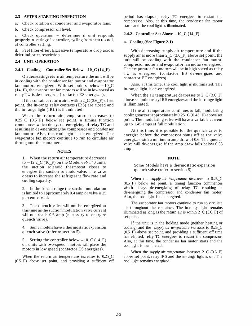
2.3 AFTER STARTING INSPECTION
a. Check rotation of condenser and evaporator fans.b. Check compressor oil level.c. Check operation --- determine if unit respondsproperly to settingof controller, cycling fromheat to cool,at controller setting.d. Feel filter-drier. Excessive temperature drop acrossdrier indicates restriction.
2.4 UNIT OPERATION
2.4.1 Cooling --- Controller Set Below ---10_C (14_F)
On decreasing return air temperature the unit will bein cooling with the condenser fan motor and evaporatorfan motors energized. With set points below ---10_C(14_F), the evaporator fan motors will be in low speed asrelay TU is de-energized (contactor ES energizes).
If the container return air is within 2_C (3.6_F) of setpoint, the in-range relay contacts (IRS) are closed andthe in-range light (IRL) is illuminated.
When the return air temperature decreases to0.25_C (0.5_F) below set point, a timing functioncommences which delays de-energizing of relay TC andresulting in de-energizing the compressor and condenserfan motor. Also, the cool light is de-energized. Theevaporator fan motors continue to run to circulate airthroughout the container.
NOTES
1. When the return air temperature decreasesto ---12.2_C (10_F) on the Model 69NT40 units,the suction solenoid thermostat closes toenergize the suction solenoid valve. The valveopens to increase the refrigerant flow rate andcooling capacity.
2. In the frozen range the suction modulationis limited to approximately 0.4 amp or valve is 25percent closed.
3. The quench valve will not be energized atthis time as the suction modulation valve currentwill not reach 0.6 amp (necessary to energizequench valve).
4. Some models have a thermostatic expansionquench valve (refer to section 5).
5. Setting the controller below ---10_C (14_F)on units with two-speed motors will place themotors in low speed (contactor ES energizes).
When the return air temperature increases to 0.25_C(0.5_F) above set point, and providing a sufficient off
period has elapsed, relay TC energizes to restart thecompressor. Also, at this time, the condenser fan motorstarts and the cool light is illuminated.
2.4.2 Controller Set Above ---10_C (14_F)
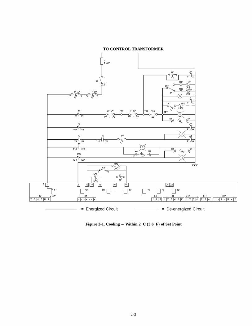
a. Cooling (See Figure 2-1)
With decreasing supply air temperature and if thesupply air is more than 2_C (3.6_F) above set point, theunit will be cooling with the condenser fan motor,compressor motor and evaporator fan motors energized.The evaporator fan motors will be in high speed as relayTU is energized (contactor ES de-energizes andcontactor EF energizes).
Also, at this time, the cool light is illuminated. Thein-range light is de-energized.
When the air temperature decreases to 2_C (3.6_F)above set point relay IRS energizes and the in-range lightis illuminated.
If the air temperature continues to fall, modulatingcooling starts at approximately 0.25_C (0.45_F) above setpoint. The modulating valve will have a variable currentup to 1.45 amps at full modulation.
At this time, it is possible for the quench valve toenergize before the compressor shuts off as the valveenergizes with a minimum amp draw of 0.6. The quenchvalve will de-energize if the amp draw falls below 0.55amp.
NOTE
Some Models have a thermostatic expansionquench valve (refer to section 5).
When the supply air temperature decreases to 0.25_C(0.5_F) below set point, a timing function commenceswhich delays de-energizing of relay TC resulting inde-energizing the compressor and condenser fan motor.Also, the cool light is de-energized.
The evaporator fan motors continue to run to circulateair throughout the container. The in-range light remainsilluminated as long as the return air is within 2_C (3.6_F) ofset point.
If the unit is in the holding mode (neither heating orcooling) and the supply air temperature increases to 0.25_C(0.5_F) above set point, and providing a sufficient off timehas elapsed, relay TC energizes to restart the compressor.Also, at this time, the condenser fan motor starts and thecool light is illuminated.
When the supply air temperature increases 2_C (3.6_F)above set point, relay IRS and the in-range light is off. Thecool light remains energized.
2-3
TO CONTROL TRANSFORMER
= Energized Circuit = De-energized Circuit
Figure 2-1. Cooling --- Within 2_C (3.6_F) of Set Point
2-4
TO CONTROL TRANSFORMER
= Energized Circuit = De-energized Circuit
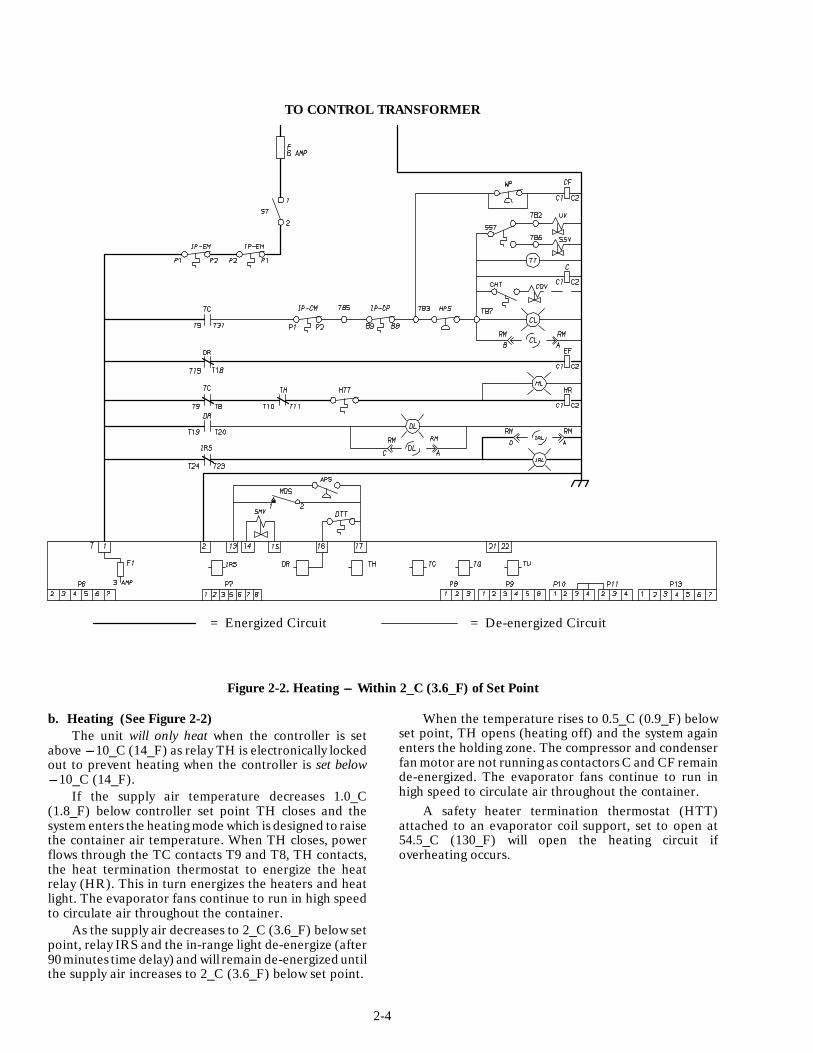
Figure 2-2. Heating --- Within 2_C (3.6_F) of Set Point
b. Heating (See Figure 2-2)The unit will only heat when the controller is set
above ---10_C (14_F) as relay TH is electronically lockedout to prevent heating when the controller is set below---10_C (14_F).
If the supply air temperature decreases 1.0_C(1.8_F) below controller set point TH closes and thesystem enters the heating mode which is designed to raisethe container air temperature. When TH closes, powerflows through the TC contacts T9 and T8, TH contacts,the heat termination thermostat to energize the heatrelay (HR). This in turn energizes the heaters and heatlight. The evaporator fans continue to run in high speedto circulate air throughout the container.
As the supply air decreases to 2_C (3.6_F) below setpoint, relay IRS and the in-range light de-energize (after90 minutes time delay) and will remain de-energized untilthe supply air increases to 2_C (3.6_F) below set point.
When the temperature rises to 0.5_C (0.9_F) belowset point, TH opens (heating off) and the system againenters the holding zone. The compressor and condenserfan motor are not running as contactors C and CF remainde-energized. The evaporator fans continue to run inhigh speed to circulate air throughout the container.
A safety heater termination thermostat (HTT)attached to an evaporator coil support, set to open at54.5_C (130_F) will open the heating circuit ifoverheating occurs.
2-5
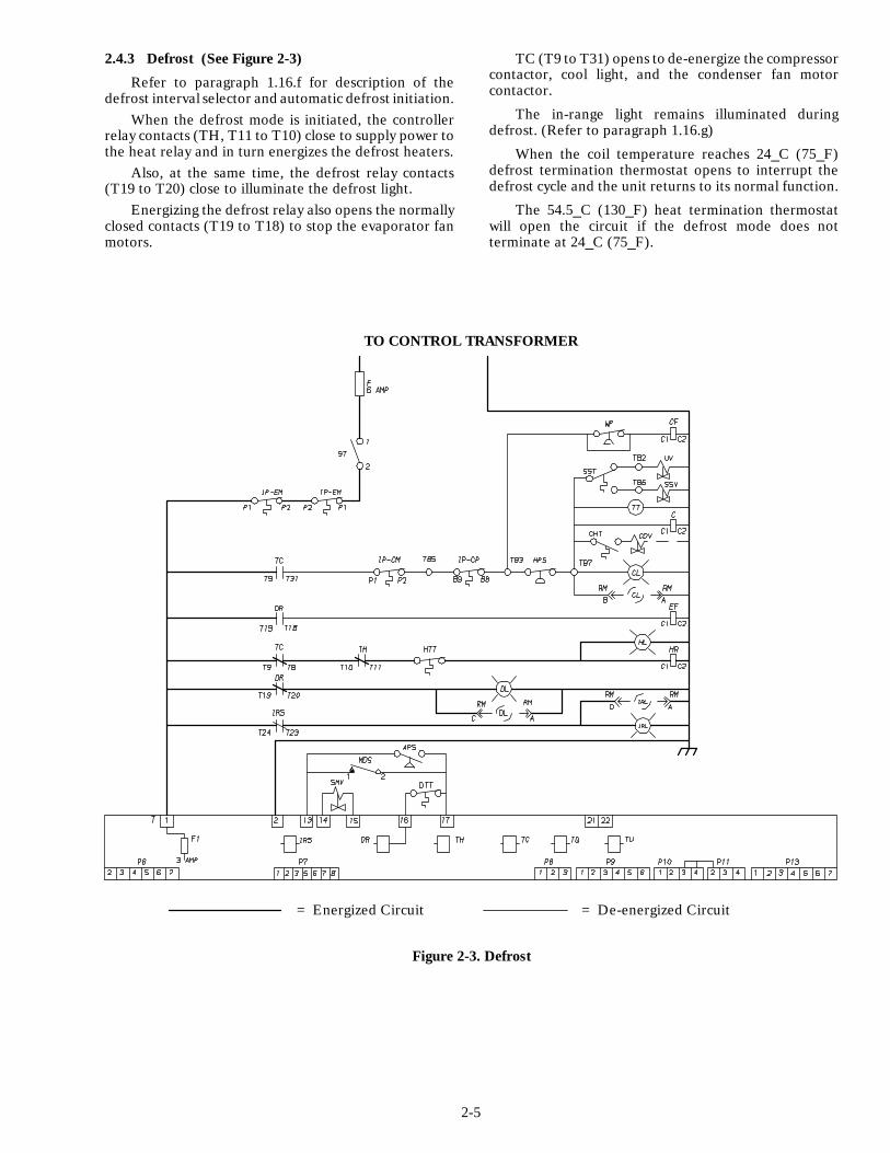
2.4.3 Defrost (See Figure 2-3)
Refer to paragraph 1.16.f for description of thedefrost interval selector and automatic defrost initiation.
When the defrost mode is initiated, the controllerrelay contacts (TH, T11 to T10) close to supply power tothe heat relay and in turn energizes the defrost heaters.
Also, at the same time, the defrost relay contacts(T19 to T20) close to illuminate the defrost light.
Energizing the defrost relay also opens the normallyclosed contacts (T19 to T18) to stop the evaporator fanmotors.
TC (T9 to T31) opens to de-energize the compressorcontactor, cool light, and the condenser fan motorcontactor.
The in-range light remains illuminated duringdefrost. (Refer to paragraph 1.16.g)
When the coil temperature reaches 24_C (75_F)defrost termination thermostat opens to interrupt thedefrost cycle and the unit returns to its normal function.
The 54.5_C (130_F) heat termination thermostatwill open the circuit if the defrost mode does notterminate at 24_C (75_F).
TO CONTROL TRANSFORMER
= Energized Circuit = De-energized Circuit
Figure 2-3. Defrost

2-6
Table 2-1. Electrical Control Positions --- Above ---10_C (14_F)
CONTROL CIRCUIT COOLING HOLDINGZONE
* Dehumidifica-tion
HEATING DEFROST
Compressor Contactor(C)
Energized De-energized Energized De-energized De-energized
Condenser Fan MotorContactor (CF) Energized De-energized Energized De-energized De-energized
One Speed EvaporatorMotor Relay (EF) Energized Energized Energized Energized De-energized
Two Speed EvaporatorMotor Relay (EF) Energized at set points above --10_C (14_F) De-energized
Two Speed EvaporatorMotor Relay (ES) De-energized at set points above --10_C (14_F)
Defrost Relay (DR) De-energized De-energized De-energized De-energized EnergizedHeater Relay (HR) De-energized De-energized Energized Energized EnergizedQuench Solenoid (QV) Refer to para-
graph 1.16.cDe-energized Refer to para-
graph 1.16.cDe-energized De-energized
CONTROLLER RELAYSDR (Defrost) OFF OFF OFF OFF ONIRS (In-Range) Closed -- If supply air is within 2_C (3.6_F) of set pointTC (Cooling) ON OFF ON OFF OFFTH (Heating) OFF OFF ON ON ONTQ (Quench) Refer to N/A N/A N/A N/ATU (Utility) paragraph 1.16.c
(Two-Speed Motors) Energized with controller settings above --10_C (14_F)INDICATING LIGHTSCool ON OFF ON OFF OFFDefrost OFF OFF OFF OFF ONIn-Range On -- If supply air is within 2_C (3.5_F) of set pointHeat OFF OFF ON ON ONPOWER CIRCUITCompressor Energized De-energized Energized De-energized De-energizedCondenser Fan Motor Energized De-energized Energized De-energized De-energizedHeaters De-energized De-energized Energized Energized EnergizedEvaporator Fan Motors Energized Energized Energized Energized De-energized* Unit with optional Humidistat (Refer to section 1.7)N/A -- Not Applicable

2-7
Table 2-2. Electrical Control Positions --- Below ---10_C (14_F)
CONTROL CIRCUIT COOLING HOLDINGZONE
**Dehumidifica-tion
HEATING DEFROST
Compressor Contactor(C)
Energized De-energized ** ** De-energized
Condenser Fan MotorContactor (CF) Energized De-energized ** ** De-energized
One Speed EvaporatorMotor Relay (EF) Energized Energized ** ** De-energized
Two Speed EvaporatorMotor Relay (EF) De-energized at set points below --10_C (14_F)
Two Speed EvaporatorMotor Relay (ES) Energized at set points below --10_C (14_F) De-energized
Defrost Relay (DR) De-energized De-energized ** ** EnergizedHeater Relay (HR) De-energized De-energized ** ** EnergizedQuench Solenoid (QV) Refer to
paragraph 1.16.cDe-energized ** ** De-energized
CONTROLLER RELAYSDR (Defrost) OFF OFF ** ** ONIRS (In-Range) Closed -- If supply air is within 2_C (3.6_F) of set pointTC (Cooling) ON OFF ** ** OFFTH (Heating) OFF OFF ** ** ONTQ (Quench) Refer to N/A ** ** N/ATU (Utility) paragraph 1.16.c
(Two-Speed Motors) Energized with controller settings below --10_C (14_F)INDICATING LIGHTSCool ON OFF ** ** OFFDefrost OFF OFF ** ** ONIn-Range On -- If supply air is within 2_C (3.5_F) of set pointHeat OFF OFF ** ** ONPOWER CIRCUITCompressor Energized De-energized ** ** De-energizedCondenser Fan Motor Energized De-energized ** ** De-energizedHeaters De-energized De-energized ** ** EnergizedEvaporator Fan Motors Energized Energized ** ** De-energized** Dehumidification and heating modes do not operate at set points below --10_C (14_F)N/A -- Not Applicable
3-1
SECTION 3
TROUBLESHOOTING
INDICATION/ POSSIBLE CAUSES REFERENCETROUBLE SECTION
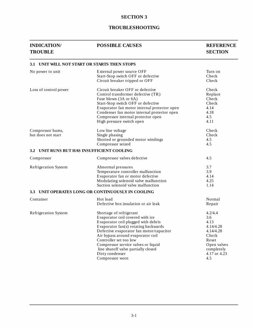
3.1 UNIT WILL NOT START OR STARTS THEN STOPS
No power to unit External power source OFF Turn onStart-Stop switch OFF or defective CheckCircuit breaker tripped or OFF Check
Loss of control power Circuit breaker OFF or defective CheckControl transformer defective (TR) ReplaceFuse blown (3A or 6A) CheckStart-Stop switch OFF or defective CheckEvaporator fan motor internal protector open 4.14Condenser fan motor internal protector open 4.18Compressor internal protector open 4.5High pressure switch open 4.11
Compressor hums, Low line voltage Checkbut does not start Single phasing Check
Shorted or grounded motor windings 4.5Compressor seized 4.5
3.2 UNIT RUNS BUT HAS INSUFFICIENT COOLING
Compressor Compressor valves defective 4.5
Refrigeration System Abnormal pressures 3.7Temperature controller malfunction 3.9Evaporator fan or motor defective 4.14Modulating solenoid valve malfunction 4.25Suction solenoid valve malfunction 1.14
3.3 UNIT OPERATES LONG OR CONTINUOUSLY IN COOLING
Container Hot load NormalDefective box insulation or air leak Repair
Refrigeration System Shortage of refrigerant 4.2/4.4Evaporator coil covered with ice 3.6Evaporator coil plugged with debris 4.13Evaporator fan(s) rotating backwards 4.14/4.28Defective evaporator fan motor/capacitor 4.14/4.28Air bypass around evaporator coil CheckController set too low ResetCompressor service valves or liquid Open valvesline shutoff valve partially closed completelyDirty condenser 4.17 or 4.23Compressor worn 4.5
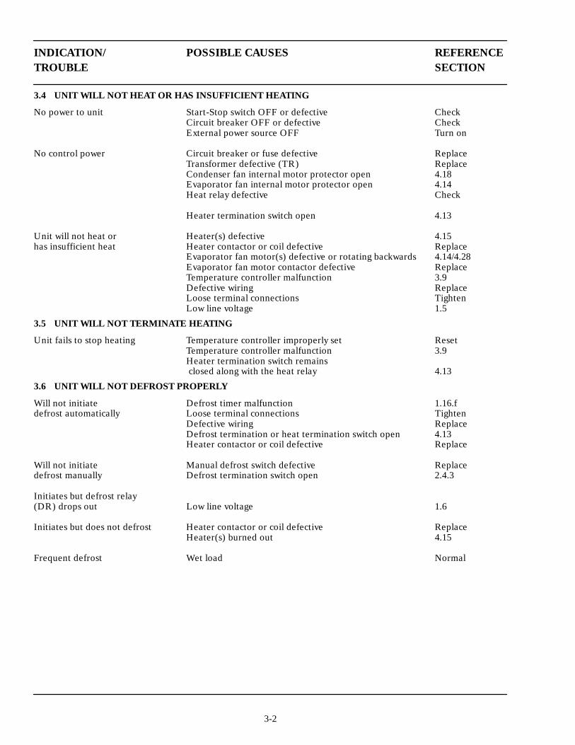
3-2
INDICATION/ POSSIBLE CAUSES REFERENCETROUBLE SECTION
3.4 UNIT WILL NOT HEAT OR HAS INSUFFICIENT HEATING
No power to unit Start-Stop switch OFF or defective CheckCircuit breaker OFF or defective CheckExternal power source OFF Turn on
No control power Circuit breaker or fuse defective ReplaceTransformer defective (TR) ReplaceCondenser fan internal motor protector open 4.18Evaporator fan internal motor protector open 4.14Heat relay defective Check
Heater termination switch open 4.13
Unit will not heat or Heater(s) defective 4.15has insufficient heat Heater contactor or coil defective Replace
Evaporator fan motor(s) defective or rotating backwards 4.14/4.28Evaporator fan motor contactor defective ReplaceTemperature controller malfunction 3.9Defective wiring ReplaceLoose terminal connections TightenLow line voltage 1.5
3.5 UNIT WILL NOT TERMINATE HEATING
Unit fails to stop heating Temperature controller improperly set ResetTemperature controller malfunction 3.9Heater termination switch remainsclosed along with the heat relay 4.13
3.6 UNIT WILL NOT DEFROST PROPERLY
Will not initiate Defrost timer malfunction 1.16.fdefrost automatically Loose terminal connections Tighten
Defective wiring ReplaceDefrost termination or heat termination switch open 4.13Heater contactor or coil defective Replace
Will not initiate Manual defrost switch defective Replacedefrost manually Defrost termination switch open 2.4.3
Initiates but defrost relay(DR) drops out Low line voltage 1.6
Initiates but does not defrost Heater contactor or coil defective ReplaceHeater(s) burned out 4.15
Frequent defrost Wet load Normal
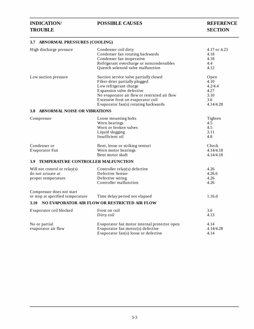
3-3
INDICATION/ POSSIBLE CAUSES REFERENCETROUBLE SECTION
3.7 ABNORMAL PRESSURES (COOLING)
High discharge pressure Condenser coil dirty 4.17 or 4.23Condenser fan rotating backwards 4.18Condenser fan inoperative 4.18Refrigerant overcharge or noncondensibles 4.4Quench solenoid valve malfunction 4.12
Low suction pressure Suction service valve partially closed OpenFilter-drier partially plugged 4.10Low refrigerant charge 4.2/4.4Expansion valve defective 4.27No evaporator air flow or restricted air flow 3.10Excessive frost on evaporator coil 3.6Evaporator fan(s) rotating backwards 4.14/4.28
3.8 ABNORMAL NOISE OR VIBRATIONS
Compressor Loose mounting bolts TightenWorn bearings 4.5Worn or broken valves 4.5Liquid slugging 3.11Insufficient oil 4.8
Condenser or Bent, loose or striking venturi CheckEvaporator Fan Worn motor bearings 4.14/4.18
Bent motor shaft 4.14/4.18
3.9 TEMPERATURE CONTROLLER MALFUNCTION
Will not control or relay(s) Controller relay(s) defective 4.26do not actuate at Defective Sensor 4.26.6proper temperature Defective wiring 4.26
Controller malfunction 4.26
Compressor does not startor stop at specified temperature Time delay period not elapsed 1.16.d
3.10 NO EVAPORATOR AIR FLOW OR RESTRICTED AIR FLOW
Evaporator coil blocked Frost on coil 3.6Dirty coil 4.13
No or partial Evaporator fan motor internal protector open 4.14evaporator air flow Evaporator fan motor(s) defective 4.14/4.28
Evaporator fan(s) loose or defective 4.14

3-4
INDICATION/ POSSIBLE CAUSES REFERENCETROUBLE SECTION
3.11 EXPANSION VALVE MALFUNCTION
Low suction pressure Low refrigerant charge 4.2/4.4with high superheat External equalizer line plugged Open
Wax, oil or dirt plugging valve or orifice 4.27Ice formation at valve seat 4.2/4.3Superheat too high 4.27.cPower assembly failure 4.27Loss of element/bulb charge 4.27Broken capillary 4.27Foreign material in valve 4.27
High suction pressure Superheat setting too low 4.27.cwith low superheat External equalizer line plugged Open
Ice holding valve open 4.2/4.3Foreign material in valve 4.27
Liquid slugging in compressor Pin and seat of expansion valve eroded orheld open by foreign material 4.27
Fluctuating suction pressure Improper bulb location or installation 4.27Low superheat setting 4.27.c
3.12 WATER-COOLED CONDENSER OR WATER PRESSURE SWITCH MALFUNCTION
High discharge pressure Dirty coil 4.23Noncondensibles 4.23
Condenser fan Water pressure switch malfunction Checkstarts and stops Water supply interruption Check
3.13 STEP-UP POWER TRANSFORMER MALFUNCTION
Unit will not start Circuit breaker (CB2) tripped CheckStep-up transformer internal protector open 4.24Step-up transformer defective 4.24Power source not turned ON Check
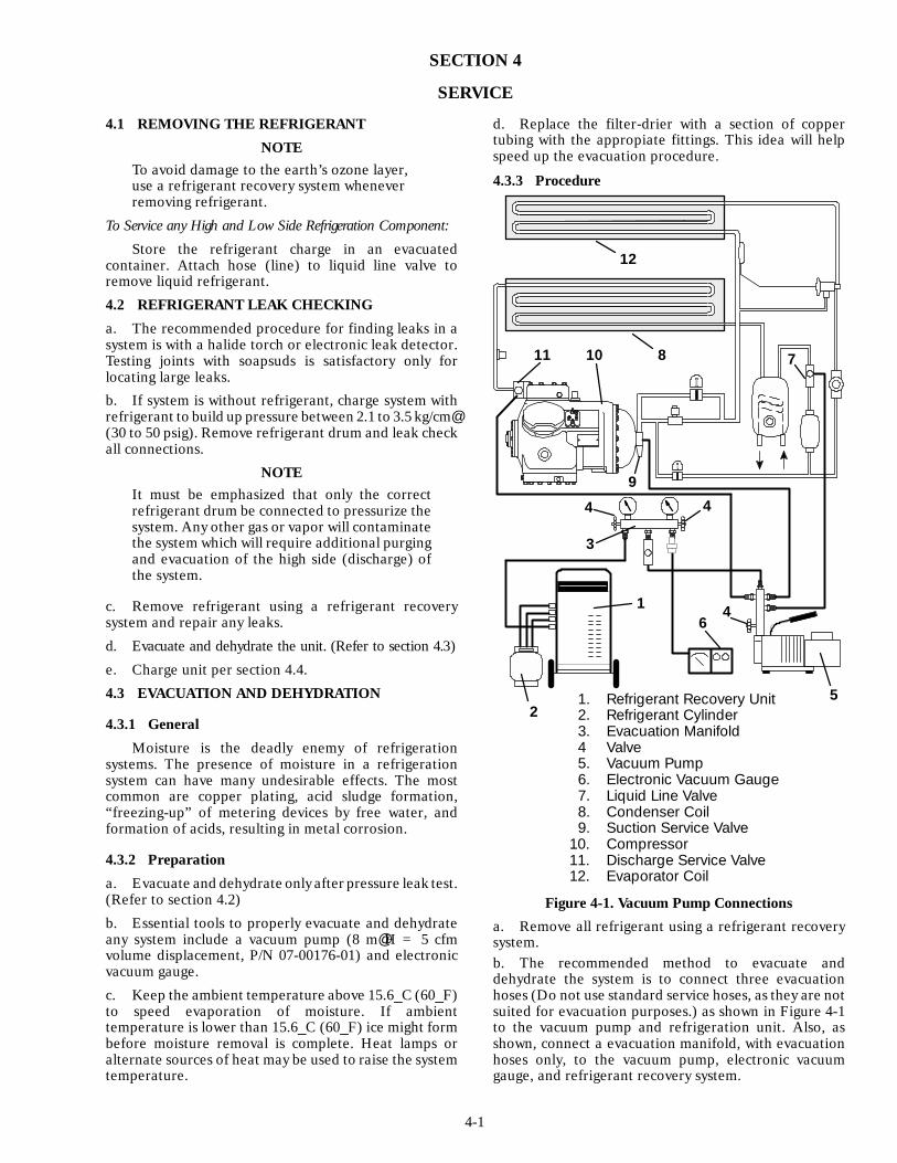
4-1
SECTION 4
SERVICE
4.1 REMOVING THE REFRIGERANT
NOTETo avoid damage to the earth’s ozone layer,use a refrigerant recovery system wheneverremoving refrigerant.
To Service any High and Low Side Refrigeration Component:
Store the refrigerant charge in an evacuatedcontainer. Attach hose (line) to liquid line valve toremove liquid refrigerant.
4.2 REFRIGERANT LEAK CHECKING
a. The recommended procedure for finding leaks in asystem is with a halide torch or electronic leak detector.Testing joints with soapsuds is satisfactory only forlocating large leaks.
b. If system is without refrigerant, charge system withrefrigerant to build up pressure between 2.1 to 3.5 kg/cm@(30 to 50 psig). Remove refrigerant drum and leak checkall connections.
NOTEIt must be emphasized that only the correctrefrigerant drum be connected to pressurize thesystem. Any other gas or vapor will contaminatethe system which will require additional purgingand evacuation of the high side (discharge) ofthe system.
c. Remove refrigerant using a refrigerant recoverysystem and repair any leaks.
d. Evacuate and dehydrate the unit. (Refer to section 4.3)
e. Charge unit per section 4.4.
4.3 EVACUATION AND DEHYDRATION
4.3.1 General
Moisture is the deadly enemy of refrigerationsystems. The presence of moisture in a refrigerationsystem can have many undesirable effects. The mostcommon are copper plating, acid sludge formation,“freezing-up” of metering devices by free water, andformation of acids, resulting in metal corrosion.
4.3.2 Preparation
a. Evacuate and dehydrate only after pressure leak test.(Refer to section 4.2)
b. Essential tools to properly evacuate and dehydrateany system include a vacuum pump (8 m@H = 5 cfmvolume displacement, P/N 07-00176-01) and electronicvacuum gauge.
c. Keep the ambient temperature above 15.6_C (60_F)to speed evaporation of moisture. If ambienttemperature is lower than 15.6_C (60_F) ice might formbefore moisture removal is complete. Heat lamps oralternate sources of heat may be used to raise the systemtemperature.
d. Replace the filter-drier with a section of coppertubing with the appropiate fittings. This idea will helpspeed up the evacuation procedure.
4.3.3 Procedure
1. Refrigerant Recovery Unit2. Refrigerant Cylinder3. Evacuation Manifold4 Valve5. Vacuum Pump6. Electronic Vacuum Gauge7. Liquid Line Valve8. Condenser Coil9. Suction Service Valve
10. Compressor11. Discharge Service Valve12. Evaporator Coil
1
2
3
4
5
6
78
9
1011
12
4
4
Figure 4-1. Vacuum Pump Connections
a. Remove all refrigerant using a refrigerant recoverysystem.b. The recommended method to evacuate anddehydrate the system is to connect three evacuationhoses (Do not use standard service hoses, as they are notsuited for evacuation purposes.) as shown in Figure 4-1to the vacuum pump and refrigeration unit. Also, asshown, connect a evacuation manifold, with evacuationhoses only, to the vacuum pump, electronic vacuumgauge, and refrigerant recovery system.
4-2
c. With the unit service valves closed (back seated) andthe vacuum pump and electronic vacuum gauge valvesopen, start the pump and draw a deep vacuum. Shut offthe pump and check to see if the vacuum holds. Thisoperation is to test the evacuation setup for leaks, repairif necessary.
d. Midseat the refrigerant system service valves.
e. Then open the vacuum pump and electronic vacuumgauge valves, if they are not already open. Start thevacuum pump. Evacuate unit until the electronic vacuumgauge indicates 2000 microns. Close the electronicvacuum gauge and vacuum pump valves. Shut off thevacuum pump. Wait a few minutes to be sure the vacuumholds.
f. Break the vacuum with clean dry refrigerant gas. Userefrigerant that the unit calls for. Raise system pressureto approximately 2 psig by monitoring it with thecompound gauge.
g. Remove refrigerant using a refrigerant recoverysystem.
h. Repeat steps e through g one time.
i. Remove the copper tubing and change thefilter-drier. Evacuate unit to 500 microns. Close theelectronic vacuum gauge and vacuum pump valves. Shutoff the vacuum pump. Wait five minutes to see if vacuumholds. This checks for residual moisture and/or leaks.
j. With a vacuum still in the unit, the refrigerant chargemay be drawn into the system from a refrigerantcontainer on weight scales. The correct amount ofrefrigerant may be added by observing the scales. (Referto section 4.4)4.4 ADDING OR CHECKING THE
REFRIGERANT CHARGE
4.4.1 Checking the Refrigerant Charge
NOTE
1. Set the controller set point to ---25_C(---13_F) to ensure that the modulating solenoidvalve is fully open when checking operation ofunit.
2. The refrigerant level should only be checkedwhen the unit is running with the modulatingsolenoid valve fully open. The containertemperature should be approximately 1.7_C(35_F) or ---17.8_C (0_F).
a. Connect the gauge manifold to the compressordischarge and suction service valves.
b. Units equipped with the optional water-cooledcondenser, check charge only on air-cooled operation.Refrigerant level on water-cooled operation will benormally above sight glass. Partially block the condensercoil inlet air starting from the front of the condenser coil.Increase the area blocked until the compressor dischargepressure is raised to approximately 12 kg/cm@ (175 psig).Refrigerant should appear at center line of sight glass onthe water-cooled condenser. If not, refer to section 4.4.3.
Units equipped with air-cooled condenser only,partially block the condenser coil inlet air starting fromthe front of the condenser coil. Increase the area blockeduntil the compressor discharge pressure increases toapproximately 13 kg/cm@ (190 psig) with the containertemperature about 2_C (35_F) or 11 kg/cm@ (160 psig)with the container temperature about ---18_C (0_F).Allow the system to stabilize for 5 minutes of continuousoperation maintaining the head pressure at the properlevel. Proceed to step c.c. For units with air-cooled condenser only, check theliquid line sight glass. If the sight glass appears clear withno bubbles visible or only occasional intermittentbubbles, then the unit has an adequate charge. If the sightglass appears to be flashing or bubbles are constantlymoving through the sight glass, then the unit may have alow refrigerant charge, or the filter-drier could bepartially plugged (refer to section 4.10). If it isdetermined that the filter-drier is not restricted, then itwill be necessary to add some refrigerant to the system.Refer to section 4.4.3.4.4.2 Adding Refrigerant to System (Full Charge)
a. Evacuate unit and leave in deep vacuum. (Refer tosection 4.3)b. Place drum of R-12 on scale and connect chargingline from drum to liquid line valve. Purge charging line atliquid line valve and then note weight of drum andrefrigerant.c. Open liquid valve on drum. Open liquid line valvehalf-way and allow the liquid refrigerant to flow into theunit until the correct weight of refrigerant has beenadded as indicated by scales. Correct charge is noted inTable 1-1.
NOTEIt may be necessary to finish charging unitthrough suction service valve in gas form, due topressure rise in high side of the system. (Refer tosection 4.4.3)
d. Backseat liquid line valve (to close off gauge port).Close liquid valve on drum. Crack connection oncharging line at liquid line valve to vent charging line.e. Start unit in cooling mode. Run approximately tenminutes and check the refrigerant charge. (Refer toparagraph 4.4.1.b)4.4.3 Adding refrigerant to System
(Partial Charge)
a. Examine the unit refrigerant system for any evidenceof leaks. Repair as necessary. (Refer to section 4.2)b. Maintain the conditions outlined in section 4.4.1.c. Fully backseat (to close off gauge port) the suctionservice valve (see Figure 1-3) and remove the 1/4 inchflare cap.d. Connect charging line between suction service valveport and drum of Refrigerant-12. Open VAPOR valve ondrum. Purge charging line.e. Partially frontseat (turn clockwise) the suctionservice valve and slowly add charge until the refrigerantappears at the proper level (refer to section 4.4.1).
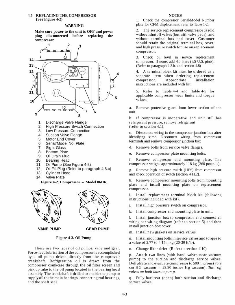
4-3
4.5 REPLACING THE COMPRESSOR(See Figure 4-2)
WARNINGMake sure power to the unit is OFF and powerplug disconnected before replacing thecompressor.
1 2 3
4
5
6789
10
11
12
1314
1. Discharge Valve Flange2. High Pressure Switch Connection3. Low Pressure Connection4. Suction Valve Flange5. Motor End Cover6. Serial/Model No. Plate7. Sight Glass8. Bottom Plate9. Oil Drain Plug
10. Bearing Head11. Oil Pump (See Figure 4-3)12. Oil Fill Plug (Refer to paragraph 4.8.c)13. Cylinder Head14. Valve Plate
Figure 4-2. Compressor --- Model 06DR
GEAR PUMPVANE PUMP
Figure 4-3. Oil Pump
There are two types of oil pumps; vane and gear.Force-feed lubrication of the compressor is accomplishedby a oil pump driven directly from the compressorcrankshaft. Refrigeration oil is drawn from thecompressor crankcase through the oil filter screen andpick up tube to the oil pump located in the bearing headassembly. The crankshaft is drilled to enable the pump tosupply oil to the main bearings, connecting rod bearings,and the shaft seal.
NOTES1. Check the compressor Serial/Model Numberplate for CFM displacement, refer to Table 1-2.2. The service replacement compressor is soldwithout shutoff valves (but with valve pads), andwithout terminal box and cover. Customershould retain the original terminal box, cover,and high pressure switch for use on replacementcompressor.3. Check oil level in service replacementcompressor. If none, add 4.0 liters (8.5 U.S. pints).(Refer to paragraph 1.3.b. and section 4.8)4. A terminal block kit must be ordered as aseparate item when ordering replacementcompressor. Appropriate installationinstructions are included with kit.
5. Refer to Table 4-4 and Table 4-5 forapplicable compressor wear limits and torquevalues.
a. Remove protective guard from lower section of theunit.
b. If compressor is inoperative and unit still hasrefrigerant pressure, remove refrigerant(refer to section 4.1).
c. Disconnect wiring in the compressor junction box afteridentifying same. Disconnect wiring from compressorterminals and remove compressor junction box.
d. Remove bolts from service valve flanges.
e. Remove compressor plate mounting bolts.
f. Remove compressor and mounting plate. Thecompressor weighs approximately 118 kg (260 pounds).
g. Remove high pressure switch (HPS) from compressorand check operation of switch (section 4.11.2).
h. Remove compressor mounting bolts from mountingplate and install mounting plate on replacementcompressor.
i. Install replacement terminal block kit (followinginstructions included with kit).
j. Install high pressure switch on compressor.
k. Install compressor and mounting plate in unit.
l. Install junction box to compressor and connect allwiring per wiring diagram (refer to section 5) and theninstall junction box cover.
m. Install new gaskets on service valves.
n. Install mounting bolts in service valves and torque toa value of 2.77 to 4.15 mkg (20-30 ft/lb).
o. Change filter-drier. (Refer to section 4.10)
p. Attach two lines (with hand valves near vacuumpump) to the suction and discharge service valves.Dehydrate and evacuate compressor to 500 microns (75.9cm HG vacuum = 29.90 inches Hg vacuum). Turn offvalves on both lines to pump.
q. Fully backseat (open) both suction and dischargeservice valves.
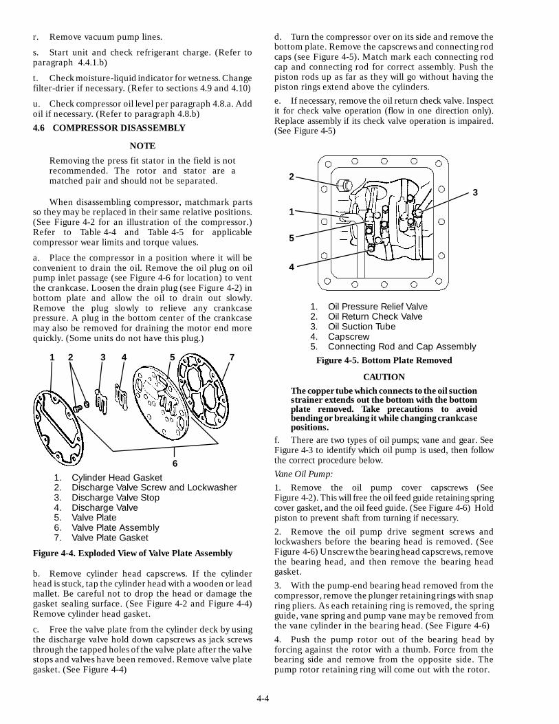
4-4
r. Remove vacuum pump lines.
s. Start unit and check refrigerant charge. (Refer toparagraph 4.4.1.b)
t. Check moisture-liquid indicator for wetness. Changefilter-drier if necessary. (Refer to sections 4.9 and 4.10)
u. Check compressor oil level per paragraph 4.8.a. Addoil if necessary. (Refer to paragraph 4.8.b)4.6 COMPRESSOR DISASSEMBLY
NOTE
Removing the press fit stator in the field is notrecommended. The rotor and stator are amatched pair and should not be separated.
When disassembling compressor, matchmark partsso they may be replaced in their same relative positions.(See Figure 4-2 for an illustration of the compressor.)Refer to Table 4-4 and Table 4-5 for applicablecompressor wear limits and torque values.
a. Place the compressor in a position where it will beconvenient to drain the oil. Remove the oil plug on oilpump inlet passage (see Figure 4-6 for location) to ventthe crankcase. Loosen the drain plug (see Figure 4-2) inbottom plate and allow the oil to drain out slowly.Remove the plug slowly to relieve any crankcasepressure. A plug in the bottom center of the crankcasemay also be removed for draining the motor end morequickly. (Some units do not have this plug.)
1 2 3 4 5 7
61. Cylinder Head Gasket2. Discharge Valve Screw and Lockwasher3. Discharge Valve Stop4. Discharge Valve5. Valve Plate6. Valve Plate Assembly7. Valve Plate Gasket
Figure 4-4. Exploded View of Valve Plate Assembly
b. Remove cylinder head capscrews. If the cylinderhead is stuck, tap the cylinder head with a wooden or leadmallet. Be careful not to drop the head or damage thegasket sealing surface. (See Figure 4-2 and Figure 4-4)Remove cylinder head gasket.
c. Free the valve plate from the cylinder deck by usingthe discharge valve hold down capscrews as jack screwsthrough the tapped holes of the valve plate after the valvestops and valves have been removed. Remove valve plategasket. (See Figure 4-4)
d. Turn the compressor over on its side and remove thebottom plate. Remove the capscrews and connecting rodcaps (see Figure 4-5). Match mark each connecting rodcap and connecting rod for correct assembly. Push thepiston rods up as far as they will go without having thepiston rings extend above the cylinders.e. If necessary, remove the oil return check valve. Inspectit for check valve operation (flow in one direction only).Replace assembly if its check valve operation is impaired.(See Figure 4-5)
1. Oil Pressure Relief Valve2. Oil Return Check Valve3. Oil Suction Tube4. Capscrew5. Connecting Rod and Cap Assembly
1
2
3
4
5
Figure 4-5. Bottom Plate Removed
CAUTIONThe copper tube which connects to the oil suctionstrainer extends out the bottom with the bottomplate removed. Take precautions to avoidbending or breaking it while changingcrankcasepositions.
f. There are two types of oil pumps; vane and gear. SeeFigure 4-3 to identify which oil pump is used, then followthe correct procedure below.Vane Oil Pump:1. Remove the oil pump cover capscrews (SeeFigure 4-2). This will free the oil feed guide retaining springcover gasket, and the oil feed guide. (See Figure 4-6) Holdpiston to prevent shaft from turning if necessary.2. Remove the oil pump drive segment screws andlockwashers before the bearing head is removed. (SeeFigure 4-6) Unscrew the bearinghead capscrews, removethe bearing head, and then remove the bearing headgasket.3. With the pump-end bearing head removed from thecompressor, remove the plunger retaining rings with snapring pliers. As each retaining ring is removed, the springguide, vane spring and pump vane may be removed fromthe vane cylinder in the bearing head. (See Figure 4-6)4. Push the pump rotor out of the bearing head byforcing against the rotor with a thumb. Force from thebearing side and remove from the opposite side. Thepump rotor retaining ring will come out with the rotor.

4-5
5. A new bearing head complete with oil pump shouldbe obtained from Carrier Transicold as a replacement toeliminate oil pump trouble. However, if the cause ofpump failure can be determined in the field, replacementparts may be ordered from Carrier Transicold to repairthe pump.
8
1514
135
12
1110
9
7
6
43
21
1. Oil Pump Cover2. Cover Gasket3. Capscrews and
Lockwashers4. Oil Pump Drive5. Rotor Retaining Ring6. Pump Vane Cylinder7. Pump Vane8. Vane Spring
9. Retaining Ring10. Spring Guide11. Bearing Head12. Pump Rotor13. Oil Feed Guide14. Retainer Spring15. Capscrews and
Washers16. Oil Inlet Passage
TOP
16
4
11 5
12
3
Figure 4-6. Vane Oil Pump and Bearing Head
Gear Oil Pump:
1. Remove eight capscrews and remove oil pumpbearing head assembly, gasket and thrust washer. (SeeFigure 4-7)
2. If it was determined that the oil pump was notoperating properly, the entire oil pump and bearing headassembly must be replaced. Replacement parts for thepump are not available.
2
1
34
1. Oil Pump & Bearing Head2. Thrust Washer (Gear Pump Only)3. Oil Pickup Tube4. Oil Inlet Port
Figure 4-7. Gear Oil Pump and Bearing Head
g. Be very careful not to damage the motor windingswhen removing the motor end cover as the cover fits overthe winding coils. Remove all capscrews except one in thetop of the cover. Then, while holding the cover in place,remove the remaining capscrew. Do not allow the coverto drop from its own weight. To prevent striking thewinding, move the cover off horizontally and in line withthe motor axis.h. Remove the refrigerant suction strainer and if it isremoved with ease it may be cleaned with solvent andreplaced. (See Figure 4-8) If the strainer is broken,corroded or clogged with dirt that is not easily removed,replace the strainer. Install newgaskets upon reassembly.
1234567
1. Valve Capscrew2. Suction Service Valve3. Valve Gasket4. Motor End Cover5. Motor End Cover Gasket6. Suction Strainer7. Strainer Screws and Washers
Figure 4-8. Motor End Cover
i. Block the compressor crankshaft so that it cannotturn. Use a screw driver to bend back the tabs on thelockwasher and remove the equalizer tube. (SeeFigure 4-10) The slinger at the end of the shaft draws
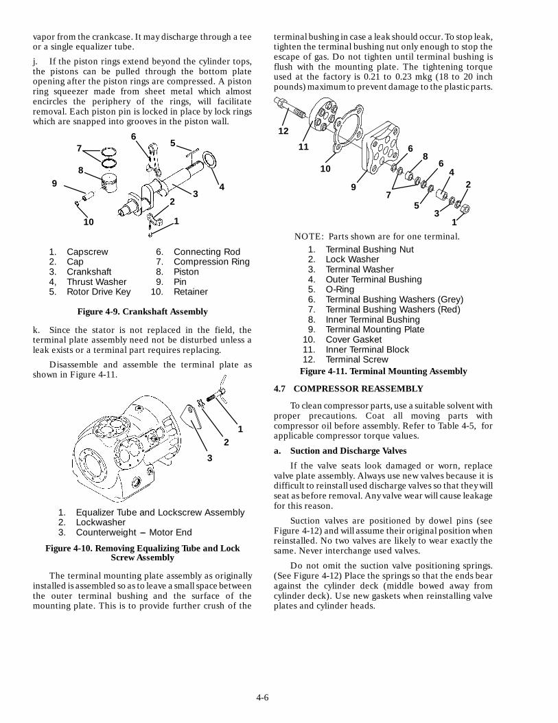
4-6
vapor from the crankcase. It may discharge through a teeor a single equalizer tube.
j. If the piston rings extend beyond the cylinder tops,the pistons can be pulled through the bottom plateopening after the piston rings are compressed. A pistonring squeezer made from sheet metal which almostencircles the periphery of the rings, will facilitateremoval. Each piston pin is locked in place by lock ringswhich are snapped into grooves in the piston wall.
1
23
4
56
7
89
10
1. Capscrew2. Cap3. Crankshaft4, Thrust Washer5. Rotor Drive Key
6. Connecting Rod7. Compression Ring8. Piston9. Pin
10. Retainer
Figure 4-9. Crankshaft Assembly
k. Since the stator is not replaced in the field, theterminal plate assembly need not be disturbed unless aleak exists or a terminal part requires replacing.
Disassemble and assemble the terminal plate asshown in Figure 4-11.
1. Equalizer Tube and Lockscrew Assembly2. Lockwasher3. Counterweight --- Motor End
12
3
Figure 4-10. Removing Equalizing Tube and LockScrew Assembly
The terminal mounting plate assembly as originallyinstalled is assembled so as to leave a small space betweenthe outer terminal bushing and the surface of themounting plate. This is to provide further crush of the
terminal bushing in case a leak should occur. To stop leak,tighten the terminal bushing nut only enough to stop theescape of gas. Do not tighten until terminal bushing isflush with the mounting plate. The tightening torqueused at the factory is 0.21 to 0.23 mkg (18 to 20 inchpounds) maximumto prevent damage to the plasticparts.
NOTE: Parts shown are for one terminal.1. Terminal Bushing Nut2. Lock Washer3. Terminal Washer4. Outer Terminal Bushing5. O-Ring6. Terminal Bushing Washers (Grey)7. Terminal Bushing Washers (Red)8. Inner Terminal Bushing9. Terminal Mounting Plate
10. Cover Gasket11. Inner Terminal Block12. Terminal Screw
12
11
10
97
53
1
24
68
6
Figure 4-11. Terminal Mounting Assembly
4.7 COMPRESSOR REASSEMBLY
To clean compressor parts, use a suitable solvent withproper precautions. Coat all moving parts withcompressor oil before assembly. Refer to Table 4-5, forapplicable compressor torque values.
a. Suction and Discharge Valves
If the valve seats look damaged or worn, replacevalve plate assembly. Always use new valves because it isdifficult to reinstall used discharge valves so that they willseat as before removal. Any valve wear will cause leakagefor this reason.
Suction valves are positioned by dowel pins (seeFigure 4-12) and will assume their original position whenreinstalled. No two valves are likely to wear exactly thesame. Never interchange used valves.
Do not omit the suction valve positioning springs.(See Figure 4-12) Place the springs so that the ends bearagainst the cylinder deck (middle bowed away fromcylinder deck). Use new gaskets when reinstalling valveplates and cylinder heads.

4-7
1. Suction Valve Positioning Spring2. Suction Valve3. Valve Plate Dowel Pin
1
2
3
Figure 4-12. Suction Valve and Positioning Springs
b. Compression Rings
1. Depending on date of manufacture, thecompressor may be equipped with double or single ringpistons. This variation may also exist with replacementpiston assemblies. If double ring pistons and ring sets areto be installed, both compression rings must be installed.Also, double ring and single ring pistons may be installedin the compressor.
2. The compression ring is chamfered on the insidecircumference. This ring is installed with the chamfertowards the top. If using a double ring piston, stagger thering end gaps so they are not aligned.
The gap between the ends of the piston rings canbe checked with a feeler gauge by inserting the ring intothe piston bore about one inch below the top of the bore.Square the ring in the bore by pushing it slightly with apiston. The maximum and minimum allowable ring gapsare 0.33 and 0.127 mm (0.013 and 0.005 inch)
Compression Ring
Figure 4-13. Piston Rings
C. Installing the Components
1. Install the crankshaft through the pump end ofthe compressor. Do not damage main bearings. Pushpistons from the inside of the crankcase through thecylinders being careful not to break the rings. Placechamfered side of connecting rod against radius ofcrankpins. Install matching connecting rod caps throughbottom cover plate.
2. The oil screen (located in the bottom of thecrankcase), is connected to the inlet of the oil pump.Whenever the compressor crankcase is opened, inspect
the screen for holes or an accumulation of dirt. Thescreen can be cleaned with a suitable solvent.
There are two types of oil pumps; vane and gear. SeeFigure 4-3 to identify which oil pump is used, then followthe correct procedure below.
Vane Oil Pump (See Figure 4-6):
a. Install the bearing head assembly with a new gasketon the compressor crankshaft. Carefully push oil pumpon by hand ensuring that the bearing head mounts flushto the crankcase body. The top of the bearing head ismarked on the mounting flange.
b. Align the gasket and install the eight capscrews in themounting flange.
c. Install the drive segment with the two capscrews andlock washer.
d. Insert the oil feed guide with the large diameter in.Insert the guide retaining spring so that it fits over thesmaller diameter of the feed guide. The pump cover cannow be installed.
e. Place the pump cover, with a new gasket, over theguide retaining spring and compress the spring to enableinstallation of the cover capscrews.
Gear Oil Pump (See Figure 4-7):
a. Install the pump end thrust washer on the two dowelpins located on the bearing head.
CAUTIONEnsure that the thrust washer does not fall offthe dowel pins while installing the oil pump.
b. Install the bearing head assembly with a new gasketon the compressor crankshaft. Carefully push the oilpump on by hand ensuring that the thrust washer remainson the dowel pins, the tang on the end of the drivesegment engages the slot in the crankshaft, and the oilinlet port on the pump is aligned with the oil pickup tubein the crankcase. The pump should mount flush with thecrankcase.
c. Align the gasket and install the eight capscrews in themounting flange.
3. Install rotor with key. Screw on equalizer tubeand lock screw assembly with lock washer and bend overtabs of lock washer. Assemble suction strainer to motorand cover and bolt cover to crankcase. Assemble valveplates and gaskets. Assemble cylinder heads and gaskets.Feel if the shaft will turn by hand.
4. Install oil suction screen and bottom plate.4.8 CHECKING THE COMPRESSOR
OIL LEVELa. To Check the Oil Level in the Compressor:
1. Operate the unit in six cylinder cooling for atleast 20 minutes.
2. Check the front oil sight glass on the compressorto ensure that no foaming of the oil is present after 20minutes of operation. If the oil is foaming excessivelyafter 20 minutes of operation, check the refrigerantsystem for flood-back of liquid refrigerant. Correct thissituation before performing step a.3.

4-8
3. Turn unit off and the correct oil level should bebetween 1/4 and 1/2 of the sight glass. If the level is above1/2, oil must be removed from the compressor. To removeoil from the compressor, follow step d. If the level is below1/8, add oil to the compressor following step b. below.b. Adding Oil with Compressor in System
Two methods for adding oil are the oil pump methodand closed system method.
1. Oil Pump Method:
One compressor oil pump that may be purchased is aRobinair, part no. 14388. This oil pump adapts to a 3.785liters (one U.S. gallon) metal refrigeration oil containerand pumps 0.0725 liters (3 and 1/2 ounces) per strokewhen connected to the suction service valve port. Alsothere is no need to remove pump from can after each use.
When the compressor is in operation, the pumpcheck valve prevents the loss of refrigerant, whileallowing servicemen to develop sufficient pressure toovercome the operating suction pressure to add oil asnecessary.
Backseat suction service valve and connect oilcharging hose to port. Crack the service valve and purgethe oil hose at oil pump. Add oil as necessary.
2. Closed System Method:
In an emergency where an oil pump is not available,oil may be drawn into the compressor through the suctionservice valve.
CAUTION
Extreme care must be taken to ensure themanifold common connection remainsimmersed in oil at all times. Otherwise air andmoisture will be drawn into the compressor.
Connect the suction connection of the gaugemanifold to the compressor suction service valve port,and immerse the common connection of the gaugemanifold in an open container of refrigeration oil. Crackthe suction service valve and gauge valve to vent a smallamount of refrigerant through the common connectionand the oil to purge the lines of air. Close the gaugemanifold valve.
With the unit running, frontseat the suction servicevalve and pull a vacuum in the compressor crankcase.SLOWLY crack the suction gauge manifold valve and oilwill flow through the suction service valve into thecompressor. Add oil as necessary.
Run unit for 20 minutes, in cooling, and check oil level.
c. Adding Oil to Service Replacement Compressor
NOTE
The correct oil charge is 4.0 liters pints (8.5 U.S.).
Service replacement compressors may or may not beshipped with oil.
If compressor is without oil:
Add oil, (paragraphs 1.3.b and 4.8.b) through thesuction service valve flange cavity or by removing the oil
fill plug (see Figure 4-2). Some compressors have the oilplug located on the crankcase, at the right or left side ofthe oil pump.d. To Remove Oil From an 06DR Compressor:
1. If the oil level recorded in step a.3 is above 1/2 ofthe sight glass, oil must be removed from the compressor.
2. Close (frontseat) suction service valve and pumpunit down to 0.2 to 0.3 kg/cm@ (2 to 4 psig). Frontseatdischarge service valve and slowly bleed remainingrefrigerant.
3. Remove the oil drain plug on the bottom plate ofthe compressor and drain the proper amount of oil fromthe compressor to obtain the 1/2 sight glass maximumlevel. Replace the plug securely back into the compressor.DO NOT FORGET TO OPEN SUCTION ANDDISCHARGE SERVICE VALVES.
4. Repeat Step a. to ensure proper oil level.4.9 CHECKING OR REPLACING MOISTURE-
LIQUID INDICATORWhen the refrigeration system is operating, the
moisture-liquid indicator provides an indication ofmoisture in the system.
The indicator element is highly sensitive to moistureand will gradually change color in direct relation to anincrease or decrease in the moisture content of thesystem. The safe, caution, and unsafe system operatingconditions are then easily determined by matching theelement color with the colors displayed on the referencelabel.
To change indicator or lens:
a. Pump down the unit per section 4.1 and install newindicator or lens.
b. Evacuate the unit per section 4.3 and add refrigerantcharge per section 4.4.
c. Start unit and after twelve hours re-check indicator.If indicator does not indicate a safe condition, pump unitdown and change filter-drier. (Refer to section 4.10)4.10 CHECKING OR REPLACING THE
FILTER-DRIERIf the sight glass appears to be flashing or bubbles are
constantly moving through the sight glass, the unit mayhave a low refrigerant charge, or the filter-drier could bepartially plugged.
To Check Filter-Drier:
a. One test for a restricted or plugged filter-drier is byfeeling the liquid line inlet and outlet connections of thedrier cartridge. If the outlet side feels cooler than theinlet side, then the filter-drier should be changed.
b. Another test is that the moisture-liquid indicatorshows moisture in the system (refer to section 4.9).
To Replace Filter-Drier:
a. Remove the refrigerant (refer to section 4.1).
b. Remove filter-drier clamp, then replace drier.
c. Evacuate the unit per section 4.3.
d. Charge unit with refrigerant per section 4.4.1.
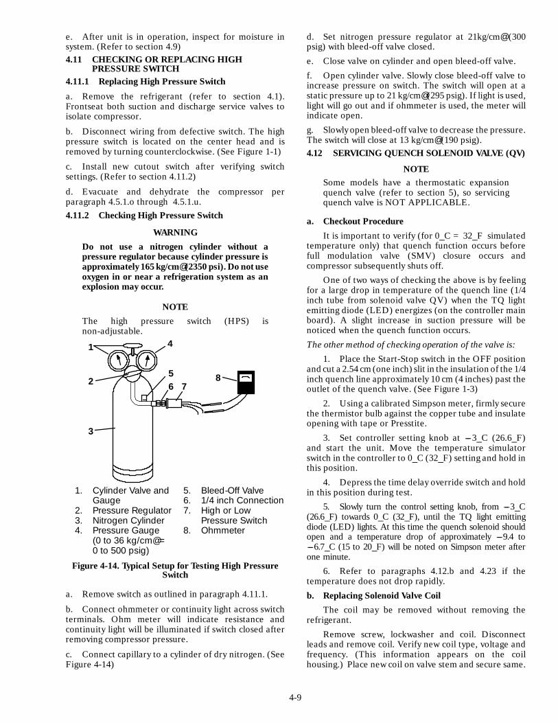
4-9
e. After unit is in operation, inspect for moisture insystem. (Refer to section 4.9)4.11 CHECKING OR REPLACING HIGH
PRESSURE SWITCH4.11.1 Replacing High Pressure Switch
a. Remove the refrigerant (refer to section 4.1).Frontseat both suction and discharge service valves toisolate compressor.
b. Disconnect wiring from defective switch. The highpressure switch is located on the center head and isremoved by turning counterclockwise. (See Figure 1-1)
c. Install new cutout switch after verifying switchsettings. (Refer to section 4.11.2)
d. Evacuate and dehydrate the compressor perparagraph 4.5.1.o through 4.5.1.u.4.11.2 Checking High Pressure Switch
WARNINGDo not use a nitrogen cylinder without apressure regulator because cylinder pressure isapproximately 165 kg/cm@ (2350 psi). Do not useoxygen in or near a refrigeration system as anexplosion may occur.
NOTEThe high pressure switch (HPS) isnon-adjustable.
1. Cylinder Valve andGauge
2. Pressure Regulator3. Nitrogen Cylinder4. Pressure Gauge
(0 to 36 kg/cm@ =0 to 500 psig)
5. Bleed-Off Valve6. 1/4 inch Connection7. High or Low
Pressure Switch8. Ohmmeter
1
2
3
4
56 7
8
Figure 4-14. Typical Setup for Testing High PressureSwitch
a. Remove switch as outlined in paragraph 4.11.1.
b. Connect ohmmeter or continuity light across switchterminals. Ohm meter will indicate resistance andcontinuity light will be illuminated if switch closed afterremoving compressor pressure.
c. Connect capillary to a cylinder of dry nitrogen. (SeeFigure 4-14)
d. Set nitrogen pressure regulator at 21kg/cm@ (300psig) with bleed-off valve closed.
e. Close valve on cylinder and open bleed-off valve.
f. Open cylinder valve. Slowly close bleed-off valve toincrease pressure on switch. The switch will open at astatic pressure up to 21 kg/cm@ (295 psig). If light is used,light will go out and if ohmmeter is used, the meter willindicate open.
g. Slowly open bleed-off valve to decrease the pressure.The switch will close at 13 kg/cm@ (190 psig).4.12 SERVICING QUENCH SOLENOID VALVE (QV)
NOTESome models have a thermostatic expansionquench valve (refer to section 5), so servicingquench valve is NOT APPLICABLE.
a. Checkout Procedure
It is important to verify (for 0_C = 32_F simulatedtemperature only) that quench function occurs beforefull modulation valve (SMV) closure occurs andcompressor subsequently shuts off.
One of two ways of checking the above is by feelingfor a large drop in temperature of the quench line (1/4inch tube from solenoid valve QV) when the TQ lightemitting diode (LED) energizes (on the controller mainboard). A slight increase in suction pressure will benoticed when the quench function occurs.
The other method of checking operation of the valve is:
1. Place the Start-Stop switch in the OFF positionand cut a 2.54 cm(one inch) slit in the insulation of the 1/4inch quench line approximately 10 cm (4 inches) past theoutlet of the quench valve. (See Figure 1-3)
2. Using a calibrated Simpson meter, firmly securethe thermistor bulb against the copper tube and insulateopening with tape or Presstite.
3. Set controller setting knob at ---3_C (26.6_F)and start the unit. Move the temperature simulatorswitch in the controller to 0_C (32_F) setting and hold inthis position.
4. Depress the time delay override switch and holdin this position during test.
5. Slowly turn the control setting knob, from ---3_C(26.6_F) towards 0_C (32_F), until the TQ light emittingdiode (LED) lights. At this time the quench solenoid shouldopen and a temperature drop of approximately ---9.4 to---6.7_C (15 to 20_F) will be noted on Simpson meter afterone minute.
6. Refer to paragraphs 4.12.b and 4.23 if thetemperature does not drop rapidly.
b. Replacing Solenoid Valve CoilThe coil may be removed without removing the
refrigerant.
Remove screw, lockwasher and coil. Disconnectleads and remove coil. Verify new coil type, voltage andfrequency. (This information appears on the coilhousing.) Place new coil on valve stem and secure same.
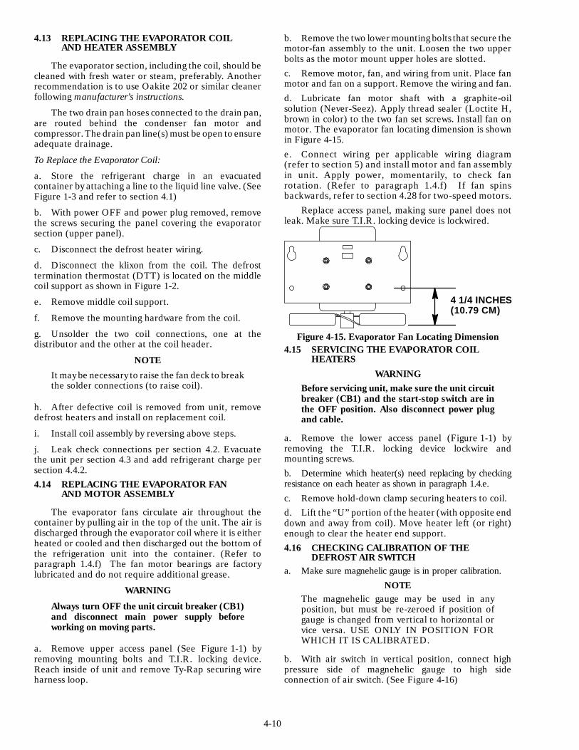
4-10
4.13 REPLACING THE EVAPORATOR COILAND HEATER ASSEMBLY
The evaporator section, including the coil, should becleaned with fresh water or steam, preferably. Anotherrecommendation is to use Oakite 202 or similar cleanerfollowing manufacturer’s instructions.
The two drain pan hoses connected to the drain pan,are routed behind the condenser fan motor andcompressor. The drain pan line(s) must be open to ensureadequate drainage.
To Replace the Evaporator Coil:
a. Store the refrigerant charge in an evacuatedcontainer by attaching a line to the liquid line valve. (SeeFigure 1-3 and refer to section 4.1)
b. With power OFF and power plug removed, removethe screws securing the panel covering the evaporatorsection (upper panel).
c. Disconnect the defrost heater wiring.
d. Disconnect the klixon from the coil. The defrosttermination thermostat (DTT) is located on the middlecoil support as shown in Figure 1-2.
e. Remove middle coil support.
f. Remove the mounting hardware from the coil.
g. Unsolder the two coil connections, one at thedistributor and the other at the coil header.
NOTE
It may be necessary to raise the fan deck to breakthe solder connections (to raise coil).
h. After defective coil is removed from unit, removedefrost heaters and install on replacement coil.
i. Install coil assembly by reversing above steps.
j. Leak check connections per section 4.2. Evacuatethe unit per section 4.3 and add refrigerant charge persection 4.4.2.4.14 REPLACING THE EVAPORATOR FAN
AND MOTOR ASSEMBLY
The evaporator fans circulate air throughout thecontainer by pulling air in the top of the unit. The air isdischarged through the evaporator coil where it is eitherheated or cooled and then discharged out the bottom ofthe refrigeration unit into the container. (Refer toparagraph 1.4.f) The fan motor bearings are factorylubricated and do not require additional grease.
WARNING
Always turn OFF the unit circuit breaker (CB1)and disconnect main power supply beforeworking on moving parts.
a. Remove upper access panel (See Figure 1-1) byremoving mounting bolts and T.I.R. locking device.Reach inside of unit and remove Ty-Rap securing wireharness loop.
b. Remove the two lower mounting bolts that secure themotor-fan assembly to the unit. Loosen the two upperbolts as the motor mount upper holes are slotted.c. Remove motor, fan, and wiring from unit. Place fanmotor and fan on a support. Remove the wiring and fan.d. Lubricate fan motor shaft with a graphite-oilsolution (Never-Seez). Apply thread sealer (Loctite H,brown in color) to the two fan set screws. Install fan onmotor. The evaporator fan locating dimension is shownin Figure 4-15.e. Connect wiring per applicable wiring diagram(refer to section 5) and install motor and fan assemblyin unit. Apply power, momentarily, to check fanrotation. (Refer to paragraph 1.4.f) If fan spinsbackwards, refer to section 4.28 for two-speed motors.
Replace access panel, making sure panel does notleak. Make sure T.I.R. locking device is lockwired.
4 1/4 INCHES(10.79 CM)
Figure 4-15. Evaporator Fan Locating Dimension4.15 SERVICING THE EVAPORATOR COIL
HEATERSWARNING
Before servicing unit, make sure the unit circuitbreaker (CB1) and the start-stop switch are inthe OFF position. Also disconnect power plugand cable.
a. Remove the lower access panel (Figure 1-1) byremoving the T.I.R. locking device lockwire andmounting screws.b. Determine which heater(s) need replacing by checkingresistance on each heater as shown in paragraph 1.4.e.c. Remove hold-down clamp securing heaters to coil.d. Lift the “U” portion of the heater (with opposite enddown and away from coil). Move heater left (or right)enough to clear the heater end support.4.16 CHECKING CALIBRATION OF THE
DEFROST AIR SWITCHa. Make sure magnehelic gauge is in proper calibration.
NOTEThe magnehelic gauge may be used in anyposition, but must be re-zeroed if position ofgauge is changed from vertical to horizontal orvice versa. USE ONLY IN POSITION FORWHICH IT IS CALIBRATED.
b. With air switch in vertical position, connect highpressure side of magnehelic gauge to high sideconnection of air switch. (See Figure 4-16)
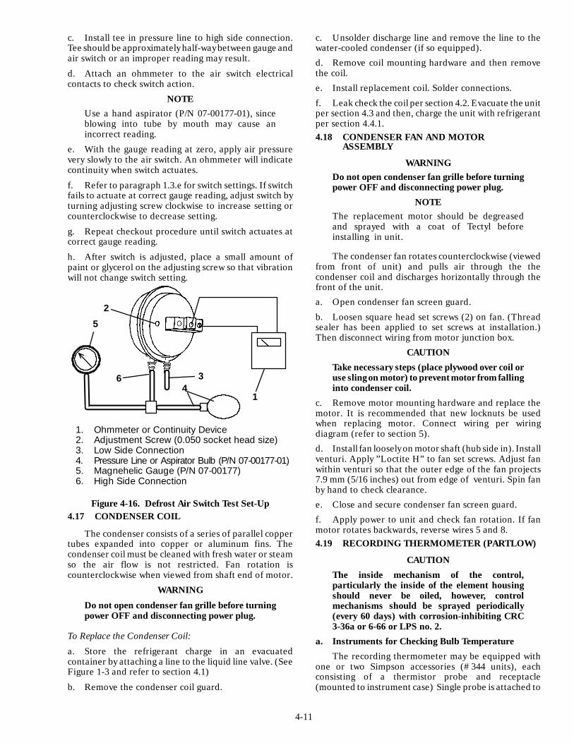
4-11
c. Install tee in pressure line to high side connection.Tee should be approximately half-way between gauge andair switch or an improper reading may result.
d. Attach an ohmmeter to the air switch electricalcontacts to check switch action.
NOTEUse a hand aspirator (P/N 07-00177-01), sinceblowing into tube by mouth may cause anincorrect reading.
e. With the gauge reading at zero, apply air pressurevery slowly to the air switch. An ohmmeter will indicatecontinuity when switch actuates.
f. Refer to paragraph 1.3.e for switch settings. If switchfails to actuate at correct gauge reading, adjust switch byturning adjusting screw clockwise to increase setting orcounterclockwise to decrease setting.
g. Repeat checkout procedure until switch actuates atcorrect gauge reading.
h. After switch is adjusted, place a small amount ofpaint or glycerol on the adjusting screw so that vibrationwill not change switch setting.
2
1
36
5
4
1. Ohmmeter or Continuity Device2. Adjustment Screw (0.050 socket head size)3. Low Side Connection4. Pressure Line or Aspirator Bulb (P/N 07-00177-01)5. Magnehelic Gauge (P/N 07-00177)6. High Side Connection
Figure 4-16. Defrost Air Switch Test Set-Up4.17 CONDENSER COIL
The condenser consists of a series of parallel coppertubes expanded into copper or aluminum fins. Thecondenser coil must be cleaned with fresh water or steamso the air flow is not restricted. Fan rotation iscounterclockwise when viewed from shaft end of motor.
WARNING
Do not open condenser fan grille before turningpower OFF and disconnecting power plug.
To Replace the Condenser Coil:
a. Store the refrigerant charge in an evacuatedcontainer by attaching a line to the liquid line valve. (SeeFigure 1-3 and refer to section 4.1)
b. Remove the condenser coil guard.
c. Unsolder discharge line and remove the line to thewater-cooled condenser (if so equipped).
d. Remove coil mounting hardware and then removethe coil.
e. Install replacement coil. Solder connections.
f. Leak check the coil per section 4.2. Evacuate the unitper section 4.3 and then, charge the unit with refrigerantper section 4.4.1.4.18 CONDENSER FAN AND MOTOR
ASSEMBLY
WARNINGDo not open condenser fan grille before turningpower OFF and disconnecting power plug.
NOTEThe replacement motor should be degreasedand sprayed with a coat of Tectyl beforeinstalling in unit.
The condenser fan rotates counterclockwise (viewedfrom front of unit) and pulls air through the thecondenser coil and discharges horizontally through thefront of the unit.
a. Open condenser fan screen guard.
b. Loosen square head set screws (2) on fan. (Threadsealer has been applied to set screws at installation.)Then disconnect wiring from motor junction box.
CAUTION
Take necessary steps (place plywood over coil oruse slingon motor) to preventmotor from fallinginto condenser coil.
c. Remove motor mounting hardware and replace themotor. It is recommended that new locknuts be usedwhen replacing motor. Connect wiring per wiringdiagram (refer to section 5).
d. Install fan loosely on motor shaft (hub side in). Installventuri. Apply ”Loctite H” to fan set screws. Adjust fanwithin venturi so that the outer edge of the fan projects7.9 mm (5/16 inches) out from edge of venturi. Spin fanby hand to check clearance.
e. Close and secure condenser fan screen guard.
f. Apply power to unit and check fan rotation. If fanmotor rotates backwards, reverse wires 5 and 8.4.19 RECORDING THERMOMETER (PARTLOW)
CAUTION
The inside mechanism of the control,particularly the inside of the element housingshould never be oiled, however, controlmechanisms should be sprayed periodically(every 60 days) with corrosion-inhibiting CRC3-36a or 6-66 or LPS no. 2.
a. Instruments for Checking Bulb Temperature
The recording thermometer may be equipped withone or two Simpson accessories (#344 units), eachconsisting of a thermistor probe and receptacle(mounted to instrument case) Single probe is attached to

4-12
the element (bulb) capillary which senses the containerreturn air temperature. If using two probes, the otherprobe is attached to the supply air temperature sensor.
In the event of a failure with the #344 test lead, otherinstruments for checking bulb temperatures are:
1. Simpson Meter, CTC P/N 07-00013 or RobinairThermistor Temperature Tester, Model 12860.
A resistance thermometer and a RCA lead with aphono-plug at each end may be used to compare bulbtemperature and stylus indicated temperature on chart byinserting one end of the lead into receptacle provided onthe controller and other end in the meter. Always checkresistance thermometer before using, refer to paragraph b.
2. Ohmmeter
a. Place one probe of ohmmeter in the middle ofthe receptacle provided on the chart platen and groundother probe to unit.
b. Note reading of meter and using Table 4-1,convert resistance to temperature.
3
4
1
2
5
1. Wind-up Key2. Stylus3. Set Screw
4. Pinion Shaft5. Stylus Lifter
Figure 4-17. Partlow Recording Thermometer
b. Checking Resistance Thermometer
Calibrate the resistance thermometer by completelyfilling a thermos container full of ice cubes or chips andfilling the voids between the ice with plain water. Stir thesolution until the mixture registers 0 to 0.3_C (32 to32.5_F), as indicated by a laboratory thermometer.Immerse the resistance thermometer in the 0_C (32_F)solution and check its accuracy at this temperature. With
this instrument, be certain that the recommended lengthof the check probe is immersed so that it accurately willreflect temperature. Bear in mind that this measurementchecks the test probe at 0_C (32_F) only; it is possible forthis type of instrument to be inaccurate at othertemperatures. Rezero check thermometer, if necessary,by manufacturer’s instructions.c. Checking the Recording Thermometer Bulb
TemperatureChecking temperature is accomplished by
comparing the instrument’s indicated temperature(stylus) with the known temperature existing at theelement sensing bulb. To properly check the temperatureof the recorder, the element sensing bulb should bestabilized at a temperature of 0_C (32_F). This isaccomplished by using one of the two following methods,whichever is more convenient.1. Unit Running:
Place set point at 0_C (32_F). After unit has pulleddown to this temperature, allow compressor to cycleON-OFF 3 to 5 times to be certain temperature hasstabilized at 0_C (32_F) as verified by the resistancethermometer. If the temperature indicated by thethermometer differs from 0_C (32_F) by more than0.6_C (1_F) when compressor cycles off, rezeroing mustbe performed.2. Unit Off:
Place the recording thermometer element (sensingbulb) in 0_C (32_F) ice-water bath. Ice-water bath isprepared by filling an insulated container (of sufficientsize to completely immerse bulb) with ice cubes orchipped ice, then filling voids between ice with water, andagitating until mixture reaches 0_C (32_F) as shown by alaboratory thermometer.
When the temperature at the element sensing bulbhas stabilized at 0_C (32_F), as indicated by stable stylusindication, compare temperature indicated by stylus withtemperature shown by a laboratory thermometer. If thetwo readings do not agree, the recording thermometershould be rezeroed. (Refer to paragraph d)d. Rezeroing the Recording Thermometer1. Be certain that element bulb temperature hasstabilized at 0_C (32_F). Note the amount oftemperature difference between the test meter orthermometer reading and the stylus indicatedtemperature.
If the difference noted between the known elementtemperature and indicated temperature is withinacceptable limits (0.3 of 0_C = 1/2_ of 32_F), do notattempt to rezero. If more than 0.3_C (1/2_F) invariation, carefully note the number of degrees.2. If recording thermometer is found to requirerezeroing:
a. Loosen set screw, item 3, Figure 4-17 and zerothermometer by turning pinion shaft, item 4.Lengthening pinion shaft (counterclockwise) raisesstylus indicated temperature reading: shortening shaft(clockwise) lowers stylus reading. Then retighten setscrew.
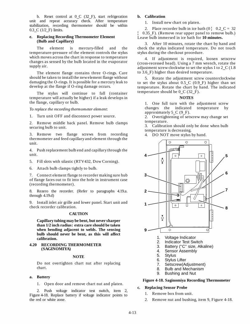
4-13
b. Reset control at 0_C (32_F), start refrigerationunit and repeat accuracy check. After temperaturestabilization, recording thermometer should be within0.3_C (1/2_F) limits.
e. Replacing Recording Thermometer Element(Bulb and Capillary)
The element is mercury-filled and thetemperature-pressure of the element controls the styluswhich moves across the chart in response to temperaturechanges as sensed by the bulb located in the evaporatorsupply air.
The element flange contains three O-rings. Careshould be taken to install the new element flange withoutdamaging the O-rings. It is possible for a mercury leak todevelop at the flange if O-ring damage occurs.
The stylus will continue to fall (containertemperature will actually be higher) if a leak develops inthe flange, capillary or bulb.
To replace the recording thermometer element:
1. Turn unit OFF and disconnect power source.
2. Remove middle back panel. Remove bulb clampssecuring bulb to unit.
3. Remove two flange screws from recordingthermometer and feed capillary and element through theunit.
4. Push replacement bulb end and capillary through theunit.
5. Fill slots with silastic (RTV432, Dow Corning).
6. Attach bulb clamps tightly to bulb.
7. Connect element flange to recorder making sure hubof flange faces out to fit into the hole in instrument case(recording thermometer).
8. Rezero the recorder. (Refer to paragraphs 4.19.a.through 4.19.d)
9. Install inlet air grille and lower panel. Start unit andcheck recorder calibration.
CAUTION
Capillary tubing may be bent, but never sharperthan 1/2 inch radius: extra care should be takenwhen bending adjacent to welds. The sensingbulb should never be bent, as this will affectcalibration.
4.20 RECORDING THERMOMETER(SAGINOMIYA)
NOTE
Do not overtighten chart nut after replacingchart.
a. Battery
1. Open door and remove chart nut and platen.
2. Push voltage indicator test switch, item 2,Figure 4-18. Replace battery if voltage indicator points tothe red or white zone.
b. Calibration1. Install new chart on platen.2. Place recorder bulb in ice bath (0 ¦ 0.2_C = 32
¦ 0.35_F). (Remove rear upper panel to remove bulb.)Leave bulb immersed in ice bath for 10 minutes.
3. After 10 minutes, rotate the chart by hand andcheck the stylus indicated temperature. Do not touchstylus during the checkout procedure.
4. If adjustment is required, loosen setscrew(cross-recessed head). Using a 7 mm wrench, rotate theadjustment screw clockwise to set the stylus 1 to 2_C (1.8to 3.6_F) higher than desired temperature.
5. Rotate the adjustment screw counterclockwiseto set the stylus about 0.5_C (0.9_F) higher than settemperature. Rotate the chart by hand. The indicatedtemperature should be 0_C (32_F).
NOTES1. One full turn with the adjustment screwchanges the indicated temperature byapproximately 5_C (9_F).2. Overtightening of setscrew may change settemperature.3. Calibration should only be done when bulbtemperature is decreasing.4. DO NOT move stylus by hand.
1. Voltage Indicator2. Indicator Test Switch3. Battery (“C” size, Alkaline)4. Sensor Assembly5. Stylus6. Stylus Lifter7. Setscrew(Adjustment)8. Bulb and Mechanism9. Bushing and Nut
1
2
3
4
9
5
6
7
8
Figure 4-18. Saginomiya Recording Thermometer
c. Replacing Sensor Probe1. Remove box from unit.2. Remove nut and bushing, item 9, Figure 4-18.
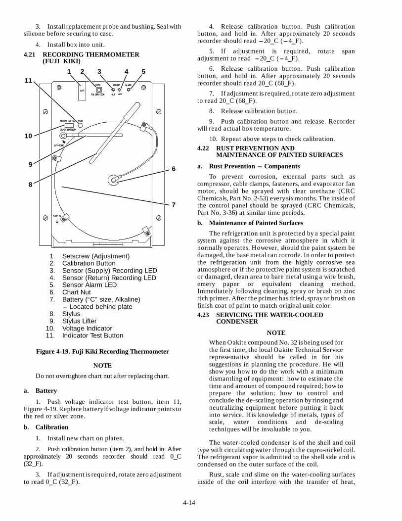
4-14
3. Install replacement probe and bushing. Sealwithsilicone before securing to case.
4. Install box into unit.4.21 RECORDING THERMOMETER
(FUJI KIKI)
1. Setscrew (Adjustment)2. Calibration Button3. Sensor (Supply) Recording LED4. Sensor (Return) Recording LED5. Sensor Alarm LED6. Chart Nut7. Battery (“C” size, Alkaline)
--- Located behind plate8. Stylus9. Stylus Lifter
10. Voltage Indicator11. Indicator Test Button
1 2 3 4 5
6
7
8
9
10
11
Figure 4-19. Fuji Kiki Recording Thermometer
NOTE
Do not overtighten chart nut after replacing chart.
a. Battery
1. Push voltage indicator test button, item 11,Figure 4-19. Replace battery if voltage indicator points tothe red or silver zone.
b. Calibration
1. Install new chart on platen.
2. Push calibration button (item 2), and hold in. Afterapproximately 20 seconds recorder should read 0_C(32_F).
3. If adjustment is required, rotate zero adjustmentto read 0_C (32_F).
4. Release calibration button. Push calibrationbutton, and hold in. After approximately 20 secondsrecorder should read ---20_C (---4_F).
5. If adjustment is required, rotate spanadjustment to read ---20_C (---4_F).
6. Release calibration button. Push calibrationbutton, and hold in. After approximately 20 secondsrecorder should read 20_C (68_F).
7. If adjustment is required, rotate zero adjustmentto read 20_C (68_F).
8. Release calibration button.
9. Push calibration button and release. Recorderwill read actual box temperature.
10. Repeat above steps to check calibration.4.22 RUST PREVENTION AND
MAINTENANCE OF PAINTED SURFACES
a. Rust Prevention --- ComponentsTo prevent corrosion, external parts such as
compressor, cable clamps, fasteners, and evaporator fanmotor, should be sprayed with clear urethane (CRCChemicals, Part No. 2-53) every six months. The inside ofthe control panel should be sprayed (CRC Chemicals,Part No. 3-36) at similar time periods.b. Maintenance of Painted Surfaces
The refrigeration unit is protected by a special paintsystem against the corrosive atmosphere in which itnormally operates. However, should the paint system bedamaged, the base metal can corrode. In order to protectthe refrigeration unit from the highly corrosive seaatmosphere or if the protective paint system is scratchedor damaged, clean area to bare metal using a wire brush,emery paper or equivalent cleaning method.Immediately following cleaning, spray or brush on zincrich primer. After the primer has dried, spray or brush onfinish coat of paint to match original unit color.4.23 SERVICING THE WATER-COOLED
CONDENSER
NOTEWhen Oakite compound No. 32 is being used forthe first time, the local Oakite Technical Servicerepresentative should be called in for hissuggestions in planning the procedure. He willshow you how to do the work with a minimumdismantling of equipment: how to estimate thetime and amount of compound required; how toprepare the solution; how to control andconclude the de-scaling operation by rinsing andneutralizing equipment before putting it backinto service. His knowledge of metals, types ofscale, water conditions and de-scalingtechniques will be invaluable to you.
The water-cooled condenser is of the shell and coiltype with circulating water through the cupro-nickel coil.The refrigerant vapor is admitted to the shell side and iscondensed on the outer surface of the coil.
Rust, scale and slime on the water-cooling surfacesinside of the coil interfere with the transfer of heat,
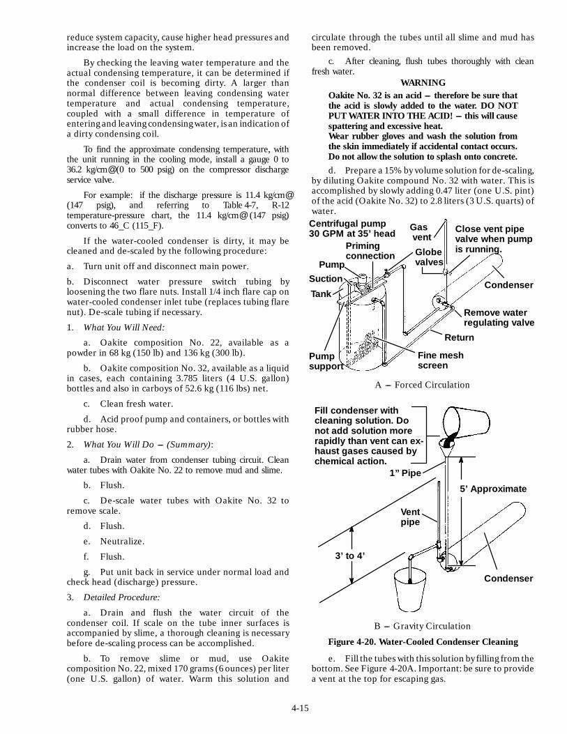
4-15
reduce system capacity, cause higher head pressures andincrease the load on the system.
By checking the leaving water temperature and theactual condensing temperature, it can be determined ifthe condenser coil is becoming dirty. A larger thannormal difference between leaving condensing watertemperature and actual condensing temperature,coupled with a small difference in temperature ofentering and leaving condensingwater, is an indication ofa dirty condensing coil.
To find the approximate condensing temperature, withthe unit running in the cooling mode, install a gauge 0 to36.2 kg/cm@ (0 to 500 psig) on the compressor dischargeservice valve.
For example: if the discharge pressure is 11.4 kg/cm@(147 psig), and referring to Table 4-7, R-12temperature-pressure chart, the 11.4 kg/cm@ (147 psig)converts to 46_C (115_F).
If the water-cooled condenser is dirty, it may becleaned and de-scaled by the following procedure:
a. Turn unit off and disconnect main power.
b. Disconnect water pressure switch tubing byloosening the two flare nuts. Install 1/4 inch flare cap onwater-cooled condenser inlet tube (replaces tubing flarenut). De-scale tubing if necessary.
1. What You Will Need:
a. Oakite composition No. 22, available as apowder in 68 kg (150 lb) and 136 kg (300 lb).
b. Oakite composition No. 32, available as a liquidin cases, each containing 3.785 liters (4 U.S. gallon)bottles and also in carboys of 52.6 kg (116 lbs) net.
c. Clean fresh water.
d. Acid proof pump and containers, or bottles withrubber hose.
2. What You Will Do --- (Summary):
a. Drain water from condenser tubing circuit. Cleanwater tubes with Oakite No. 22 to remove mud and slime.
b. Flush.
c. De-scale water tubes with Oakite No. 32 toremove scale.
d. Flush.
e. Neutralize.
f. Flush.
g. Put unit back in service under normal load andcheck head (discharge) pressure.
3. Detailed Procedure:
a. Drain and flush the water circuit of thecondenser coil. If scale on the tube inner surfaces isaccompanied by slime, a thorough cleaning is necessarybefore de-scaling process can be accomplished.
b. To remove slime or mud, use Oakitecomposition No. 22, mixed 170 grams (6 ounces) per liter(one U.S. gallon) of water. Warm this solution and
circulate through the tubes until all slime and mud hasbeen removed.
c. After cleaning, flush tubes thoroughly with cleanfresh water.
WARNINGOakite No. 32 is an acid --- therefore be sure thatthe acid is slowly added to the water. DO NOTPUT WATER INTO THE ACID! --- this will causespattering and excessive heat.Wear rubber gloves and wash the solution fromthe skin immediately if accidental contact occurs.Do not allow the solution to splash onto concrete.d. Prepare a 15%by volume solution for de-scaling,
by diluting Oakite compound No. 32 with water. This isaccomplished by slowly adding 0.47 liter (one U.S. pint)of the acid (Oakite No. 32) to 2.8 liters (3 U.S. quarts) ofwater.
Centrifugal pump30 GPM at 35’ head
PumpSuction
Pumpsupport
Tank
Fine meshscreen
Return
Remove waterregulating valve
Condenser
Globevalves
Gasvent
Close vent pipevalve when pumpis running.Priming
connection
A --- Forced Circulation
Fill condenser withcleaning solution. Donot add solution morerapidly than vent can ex-haust gases caused bychemical action.
Condenser
Ventpipe
1” Pipe
5’ Approximate
3’ to 4’
B --- Gravity Circulation
Figure 4-20. Water-Cooled Condenser Cleaning
e. Fill the tubes with this solution by filling fromthebottom. See Figure 4-20A. Important: be sure to providea vent at the top for escaping gas.
4-16
f. Allow the Oakite No. 32 solution to soak in thetube coils for several hours, periodically pump-circulating itwith an acid-proof pump.
An alternate method may be used, whereby a bottle(see Figure 4-20B) filled with the solution and attached tothe coils by a hose can serve the same purpose, by raisingand lowering of the bottle. The solution must contact thescale at every point for thorough de-scaling, thereforeensure that no air pockets exist, by regularly opening thevent to release gas. Keep flames away from the vent gases.
g. The time required for de-scaling will vary,depending upon the extent of the deposits. One way todetermine when de-scaling has been completed is totitrate the solution periodically, using titratingequipment provided free by the Oakite Technical Servicerepresentative. As scale is being dissolved, titratereadings will indicate that the Oakite No. 32 solution islosing strength. When the reading remains constant for areasonable time, this is an indication that scale has beendissolved.
h. When de-scaling is complete, drain the solutionand flush thoroughly with fresh water.
i. Next circulate a 56.7 grams (2 ounce) per liter(one U.S. gallon) solution of Oakite No. 22 through thetubes to neutralize. Drain this solution.
j. Flush the tubes thoroughly with fresh water.
NOTEIf the condenser cooling water is not being usedas drinking water or is not re-circulated in aclosed or tower system, neutralizing is notnecessary.
k. Put the unit back in service and operate undernormal load. Check the head pressure. If normal, athorough de-scaling has been achieved.
4. What You Can Do For Further Help:
Contact the Engineering and Service Department ofthe OAKITE PRODUCTS CO., 19 Rector Street, NewYork, NY 10006 U.S.A. for the name and address of theservice representative in your area.4.24 CHECKOUT PROCEDURE FOR
OPTIONAL POWER TRANSFORMER
If the unit does not start when connected to a 190/230vac power supply, check the following:
a. Make sure circuit breaker (CB2) is in the ONposition. If CB2 does not hold in, check voltage supply.
b. Check to see if the transformer internal protector(IP-AUTO-TRANS) is closed. Allow a reasonable lengthof time for transformer to cool down. The transformerincludes two (2) internal protectors. Only one is wiredinto the system as the second protector is a spare.
c. To Check for Continuity Across the Internal Protector(IP-AUTO-TRANS):
1. Turn power OFF and disconnect power source.
2. Disconnect white wires 1 and 2 from terminalboard.
3. Check for continuity across the internalprotector (IP). If (IP) is open and will not reset, connectwires 3 and 4 (18 gauge) to terminal board. Check to seeif unit will start.
d. If the internal protector and circuit breakers (CB1and CB2) are good, check the transformer. Use avoltmeter and with the primary supply circuit ON checkthe primary (input) voltage (230 vac). Next, check thesecondary (output) voltage (460 vac) at the voltageselector switch. The transformer is defective if voltage isnot available.4.25 SERVICING THE MODULATING
SOLENOID VALVE
CAUTIONIt is important to verify (for 0_C = 32_Fsimulated temperature only) that the quenchfunction occurs before full modulating valveclosure occurs and compressor shuts off. (Referto section 4.12)
a. Valve Checkout ProcedureModulation for 0_C (32_F) simulated temperature
can be verified in several ways. Without use of testequipment, listen for a change in compressor sound. Feelfor a drop in condensing air temperature as the suctionmodulating valve closes. If a gauge manifold is connectedto unit, pressures will drop as modulating valve closes.
The preferred method of monitoring controlleroutput to the modulating valve is by reading the DCvoltage between terminals 12 and 14 on the main circuitboard (temperature controller). Readings under 0.2 vdccorrespond with valve wide open. Full closure of valvecorresponds with 1.1 and 1.3 vdc.
NOTEAbove voltages are numerically equal to valvecurrents (0.2 vdc = 0.2 amp DC).
When cooling a chill load and with unit in operation,turn set pointer downscale to ---17.8_C (0_F) and notesuction pressure. (Pressure should increase afterapproximately one minute.) Slowly raise set point andjust before compressor shuts off, a significant drop insuction pressure should be noted. If no pressure change isnoticed, valve or controller malfunctioned.
b. To Replace Valve
1. Store the refrigerant in an evacuated container.
2. Remove two bolts from suction service valve.
3. Melt solder at modulating valve connection androtate valve and tubing enough to clear compressor.Remove valve and tubing. Replace defective modulatingsolenoid valve being careful to wrap body of replacementvalve with a wet cloth while brazing. The coil need not beremoved.
4. Install new suction service valve gasket andinstall bolts in suction service valve. Torque to a value of2.77 to 4.15 mkg (20 to 30 ft/lb).
5. Solder all connections and leak check same.
6. Dehydrate and evacuate the unit per section 4.3and then add refrigerant charge per section 4.4.2.
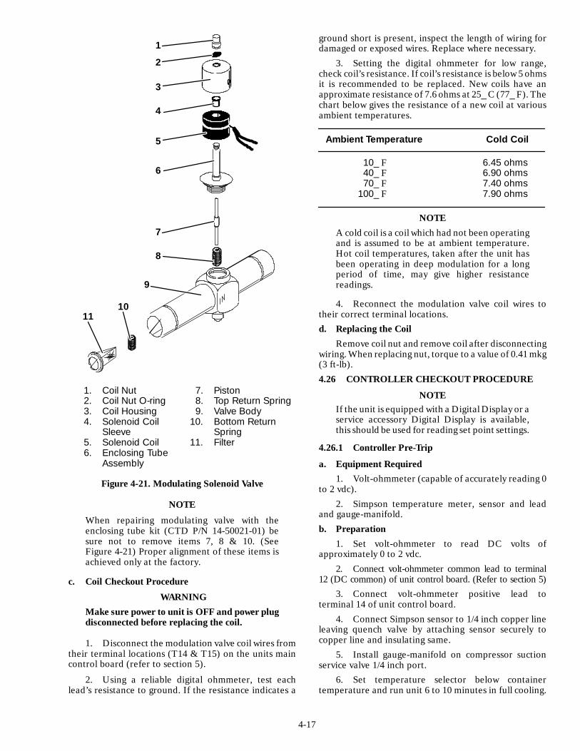
4-17
1
2
3
4
5
6
7
8
9
1011
1. Coil Nut2. Coil Nut O-ring3. Coil Housing4. Solenoid Coil
Sleeve5. Solenoid Coil6. Enclosing Tube
Assembly
7. Piston8. Top Return Spring9. Valve Body
10. Bottom ReturnSpring
11. Filter
Figure 4-21. Modulating Solenoid Valve
NOTE
When repairing modulating valve with theenclosing tube kit (CTD P/N 14-50021-01) besure not to remove items 7, 8 & 10. (SeeFigure 4-21) Proper alignment of these items isachieved only at the factory.
c. Coil Checkout Procedure
WARNINGMake sure power to unit is OFF and power plugdisconnected before replacing the coil.
1. Disconnect the modulation valve coil wires fromtheir terminal locations (T14 & T15) on the units maincontrol board (refer to section 5).
2. Using a reliable digital ohmmeter, test eachlead’s resistance to ground. If the resistance indicates a
ground short is present, inspect the length of wiring fordamaged or exposed wires. Replace where necessary.
3. Setting the digital ohmmeter for low range,check coil’s resistance. If coil’s resistance is below 5 ohmsit is recommended to be replaced. New coils have anapproximate resistance of 7.6 ohms at 25_ C (77_ F). Thechart below gives the resistance of a new coil at variousambient temperatures.
Ambient Temperature Cold Coil
10_ F 6.45 ohms40_ F 6.90 ohms70_ F 7.40 ohms
100_ F 7.90 ohms
NOTEA cold coil is a coil which had not been operatingand is assumed to be at ambient temperature.Hot coil temperatures, taken after the unit hasbeen operating in deep modulation for a longperiod of time, may give higher resistancereadings.
4. Reconnect the modulation valve coil wires totheir correct terminal locations.d. Replacing the Coil
Remove coil nut and remove coil after disconnectingwiring. When replacing nut, torque to a value of 0.41 mkg(3 ft-lb).4.26 CONTROLLER CHECKOUT PROCEDURE
NOTEIf the unit is equipped with a Digital Display or aservice accessory Digital Display is available,this should be used for reading set point settings.
4.26.1 Controller Pre-Trip
a. Equipment Required1. Volt-ohmmeter (capable of accurately reading 0
to 2 vdc).2. Simpson temperature meter, sensor and lead
and gauge-manifold.b. Preparation
1. Set volt-ohmmeter to read DC volts ofapproximately 0 to 2 vdc.
2. Connect volt-ohmmeter common lead to terminal12 (DC common) of unit control board. (Refer to section 5)
3. Connect volt-ohmmeter positive lead toterminal 14 of unit control board.
4. Connect Simpson sensor to 1/4 inch copper lineleaving quench valve by attaching sensor securely tocopper line and insulating same.
5. Install gauge-manifold on compressor suctionservice valve 1/4 inch port.
6. Set temperature selector below containertemperature and run unit 6 to 10 minutes in full cooling.

4-18
7. Set temperature selector to ---6_C (21_F).
8. Position temperature simulator switch (TSS) to0_C (32_F) position. (See Figure 1-4 or Figure 1-5) Holdtime delay override switch (TDS) in depressed position.
c. Checking Suction Modulation Valveand Quench Valve Operation
1. Note readingon volt-ohmmeter. It should be lessthan 0.3 vdc and quench valve LED should not beilluminated.
2. Note temperature reading on Simpson meter.
3. Slowly raise temperature selector setting. As thetemperature selector setting is raised, the reading on thevolt-ohmmeter will vary, increasing as temperaturesetting is moved upscale. When the temperature selectoris moved below 0_C (32_F), the voltage will remain stablemomentarily and then slowly decrease. Also, when thetemperature setting is lowered the voltage will decrease.
4. When suction modulation valve current reaches0.6 vdc on volt-ohmmeter, the quench valve light emittingdiode (LED) will energize and the temperature (Simpsonmeter reading) of the tube leaving the quench valve willdecrease showing that the quench valve opened when thesignal was sent from the control board through relay TQ.
5. When the reading on the volt-ohmmeter fallsbelow 0.5 vdc, the quench valve will de-energize and thequench valve will close.
d. In-Range Relay (IRS) Operation
Continue to raise the temperature selector setting untilthe selector reaches ---2 ¦ 0.5_C (29 ¦ 1_F) where thein-range relay and light emitting diode (LED) will energize.
e. Cooling --- Full Modulation
1. Continue to raise temperature selector setting to0.5 ¦ 0.5_C (33 ¦ 1_F). The suction modulation valvecurrent will be 0.9 to 1.2 vdc.
2. Note that the compressor suction pressure gaugereading drops between 0 psig and 50.8 cm (20 inches) Hgvacuum.
3. The quench valve LED will be illuminated and asubstantial temperature drop will be seen on the Simpsonmeter when compared to that noted at the start ofcheckout procedure.
f. Checking Heating ON and Cooling OFF
1. Continue to raise temperature selector settingto 1.0 ¦ 0.5_C (34 ¦ 1_F). The compressor andcondenser fan will cycle off and the cool (TC) LED willde-energize.
The heat relay will energize and the TH LED will beilluminated.
2. Continue to raise the temperature selectorsetting to 2 ¦ 0.5_C (36 ¦ 1_F). The in-range light andthe IRS LED will de-energize. The heat relay will remainon and the TH LED will be illuminated.
4.26.2 Temperature Control Board CheckoutProcedure with TCSM
a. Equipment Required1. Multi-Test Meter (volt-ohmmeter)
2. Clamp-on Ammeter
3. Gauge-Manifold
4. Temperature Control Simulator Module(P/N 07-00226).
NOTEAll references to the TCSM board toggleswitches (TC, TH, TQ, TU, DR and in-range)positions will be either; left (away from theboard) or right (toward the board).
b. Procedure1. Turn unit OFF and disconnect power supply.
2. Open the control box door.
3. Remove the temperature control board andinsert temperature control simulator module (TCSM).See Figure 4-22, item 3, for location of temperaturecontrol board.
4. Place switches on the simulator in the aircirculation only position. Simulator (TCSM) switches TC,TH, TQ and DR will be to the left. Switches TU andin-range will be to the left also. (Placing the in-rangeswitch to the left takes the humidistat control out of thesystem). The valve current will be in the OFF position.
5. Connect gauge-manifold to the suction anddischarge service valves.
6. Turn unit power ON. The evaporator fan motorsare running in high speed at this time. Check to see if the24 vac warning light is illuminated. This light is located onthe test board, near the return air sensor signal (TP6) testpoint. (R.A. Sensor Signal). If the 24 vac light isilluminated, stop the unit immediately and remove powersupply from unit. Check all wiring to the unit controlboard.
7. Set multi-meter to 30 vdc and plug one test leadin the TP4 jack (DC com) on the simulator board.
8. Plug other test lead in the TP1 jack (12vdc) onthe simulator board. Voltage should be 12.8 ¦ 0.8 vdc onthe multi-meter. If no voltage appears here, check powersupply.
9. Repeat step 8 for the TP2 jack 9vdc. Voltageshould be 9 ¦ 1.4 vdc. If 12 vdc appears here, recheckwiring. This can happen after replacing a component onthe unit.
10. Place IRS switch to the right. LED and IRSenergize.
11. Turn simulator IRS OFF (left). LED and IRSrelay de-energize.
12. With the evaporator fan motors running, turnTH switch ON (right). TH LED and relay energize.
13. Using clamp-on ammeter, read the amps of thefour (4) heater power leads. (Heater wiring connected tothe heat relay terminals 21, 22 and 23.) Amperage
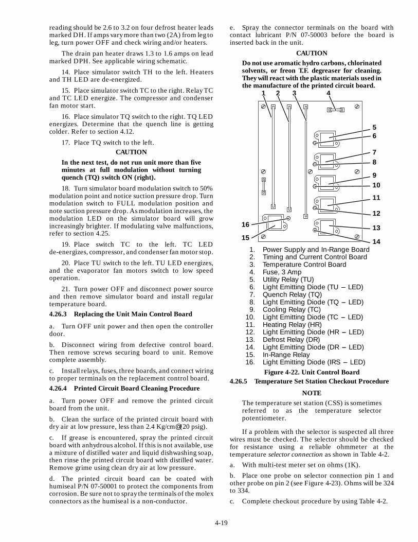
4-19
reading should be 2.6 to 3.2 on four defrost heater leadsmarked DH. If amps vary more than two (2A) from leg toleg, turn power OFF and check wiring and/or heaters.
The drain pan heater draws 1.3 to 1.6 amps on leadmarked DPH. See applicable wiring schematic.
14. Place simulator switch TH to the left. Heatersand TH LED are de-energized.
15. Place simulator switch TC to the right. Relay TCand TC LED energize. The compressor and condenserfan motor start.
16. Place simulator TQ switch to the right. TQ LEDenergizes. Determine that the quench line is gettingcolder. Refer to section 4.12.
17. Place TQ switch to the left.CAUTION
In the next test, do not run unit more than fiveminutes at full modulation without turningquench (TQ) switch ON (right).
18. Turn simulator board modulation switch to 50%modulation point and notice suction pressure drop. Turnmodulation switch to FULL modulation position andnote suction pressure drop. As modulation increases, themodulation LED on the simulator board will growincreasingly brighter. If modulating valve malfunctions,refer to section 4.25.
19. Place switch TC to the left. TC LEDde-energizes, compressor, and condenser fan motor stop.
20. Place TU switch to the left. TU LED energizes,and the evaporator fan motors switch to low speedoperation.
21. Turn power OFF and disconnect power sourceand then remove simulator board and install regulartemperature board.4.26.3 Replacing the Unit Main Control Board
a. Turn OFF unit power and then open the controllerdoor.
b. Disconnect wiring from defective control board.Then remove screws securing board to unit. Removecomplete assembly.
c. Install relays, fuses, three boards, and connect wiringto proper terminals on the replacement control board.4.26.4 Printed Circuit Board Cleaning Procedure
a. Turn power OFF and remove the printed circuitboard from the unit.
b. Clean the surface of the printed circuit board withdry air at low pressure, less than 2.4 Kg/cm@ (20 psig).
c. If grease is encountered, spray the printed circuitboard with anhydrous alcohol. If this is not available, usea mixture of distilled water and liquid dishwashing soap,then rinse the printed circuit board with distilled water.Remove grime using clean dry air at low pressure.
d. The printed circuit board can be coated withhumiseal P/N 07-50001 to protect the components fromcorrosion. Be sure not to spray the terminals of the molexconnectors as the humiseal is a non-conductor.
e. Spray the connector terminals on the board withcontact lubricant P/N 07-50003 before the board isinserted back in the unit.
CAUTIONDo not use aromatic hydro carbons, chlorinatedsolvents, or freon T.F. degreaser for cleaning.They will react with the plastic materials used inthe manufacture of the printed circuit board.
1. Power Supply and In-Range Board2. Timing and Current Control Board3. Temperature Control Board4. Fuse, 3 Amp5. Utility Relay (TU)6. Light Emitting Diode (TU --- LED)7. Quench Relay (TQ)8. Light Emitting Diode (TQ --- LED)9. Cooling Relay (TC)
10. Light Emitting Diode (TC --- LED)11. Heating Relay (HR)12. Light Emitting Diode (HR --- LED)13. Defrost Relay (DR)14. Light Emitting Diode (DR --- LED)15. In-Range Relay16. Light Emitting Diode (IRS --- LED)
1 2 3 4
56
78
910
11
12
13
14
16
15
Figure 4-22. Unit Control Board4.26.5 Temperature Set Station Checkout Procedure
NOTEThe temperature set station (CSS) is sometimesreferred to as the temperature selectorpotentiometer.
If a problem with the selector is suspected all threewires must be checked. The selector should be checkedfor resistance using a reliable ohmmeter at thetemperature selector connection as shown in Table 4-2.a. With multi-test meter set on ohms (1K).b. Place one probe on selector connection pin 1 andother probe on pin 2 (see Figure 4-23). Ohms will be 324to 334.c. Complete checkout procedure by using Table 4-2.
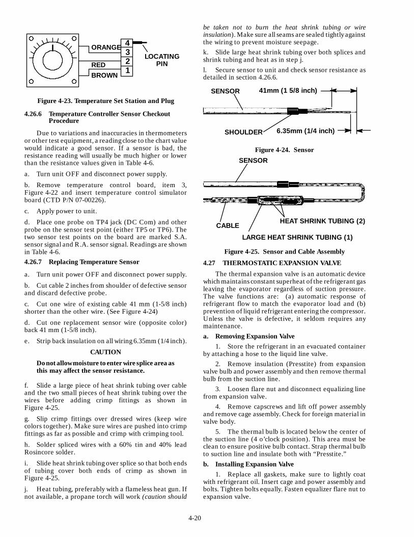
4-20
4321
ORANGE
REDBROWN
LOCATINGPIN
Figure 4-23. Temperature Set Station and Plug
4.26.6 Temperature Controller Sensor CheckoutProcedure
Due to variations and inaccuracies in thermometersor other test equipment, a readingclose to the chart valuewould indicate a good sensor. If a sensor is bad, theresistance reading will usually be much higher or lowerthan the resistance values given in Table 4-6.
a. Turn unit OFF and disconnect power supply.
b. Remove temperature control board, item 3,Figure 4-22 and insert temperature control simulatorboard (CTD P/N 07-00226).
c. Apply power to unit.
d. Place one probe on TP4 jack (DC Com) and otherprobe on the sensor test point (either TP5 or TP6). Thetwo sensor test points on the board are marked S.A.sensor signal and R.A. sensor signal. Readings are shownin Table 4-6.4.26.7 Replacing Temperature Sensor
a. Turn unit power OFF and disconnect power supply.
b. Cut cable 2 inches from shoulder of defective sensorand discard defective probe.
c. Cut one wire of existing cable 41 mm (1-5/8 inch)shorter than the other wire. (See Figure 4-24)
d. Cut one replacement sensor wire (opposite color)back 41 mm (1-5/8 inch).
e. Strip back insulation on all wiring 6.35mm (1/4 inch).
CAUTION
Do notallow moisture to enter wire splice area asthis may affect the sensor resistance.
f. Slide a large piece of heat shrink tubing over cableand the two small pieces of heat shrink tubing over thewires before adding crimp fittings as shown inFigure 4-25.
g. Slip crimp fittings over dressed wires (keep wirecolors together). Make sure wires are pushed into crimpfittings as far as possible and crimp with crimping tool.
h. Solder spliced wires with a 60% tin and 40% leadRosincore solder.
i. Slide heat shrink tubing over splice so that both endsof tubing cover both ends of crimp as shown inFigure 4-25.
j. Heat tubing, preferably with a flameless heat gun. Ifnot available, a propane torch will work (caution should
be taken not to burn the heat shrink tubing or wireinsulation). Make sure all seams are sealed tightly againstthe wiring to prevent moisture seepage.k. Slide large heat shrink tubing over both splices andshrink tubing and heat as in step j.l. Secure sensor to unit and check sensor resistance asdetailed in section 4.26.6.
SENSOR
SHOULDER
41mm (1 5/8 inch)
6.35mm (1/4 inch)
Figure 4-24. Sensor
SENSOR
CABLEHEAT SHRINK TUBING (2)
LARGE HEAT SHRINK TUBING (1)
Figure 4-25. Sensor and Cable Assembly
4.27 THERMOSTATIC EXPANSION VALVE
The thermal expansion valve is an automatic devicewhich maintains constant superheat of the refrigerant gasleaving the evaporator regardless of suction pressure.The valve functions are: (a) automatic response ofrefrigerant flow to match the evaporator load and (b)prevention of liquid refrigerant entering the compressor.Unless the valve is defective, it seldom requires anymaintenance.a. Removing Expansion Valve
1. Store the refrigerant in an evacuated containerby attaching a hose to the liquid line valve.
2. Remove insulation (Presstite) from expansionvalve bulb and power assembly and then remove thermalbulb from the suction line.
3. Loosen flare nut and disconnect equalizing linefrom expansion valve.
4. Remove capscrews and lift off power assemblyand remove cage assembly. Check for foreign material invalve body.
5. The thermal bulb is located below the center ofthe suction line (4 o’clock position). This area must beclean to ensure positive bulb contact. Strap thermal bulbto suction line and insulate both with “Presstite.”b. Installing Expansion Valve
1. Replace all gaskets, make sure to lightly coatwith refrigerant oil. Insert cage and power assembly andbolts. Tighten bolts equally. Fasten equalizer flare nut toexpansion valve.
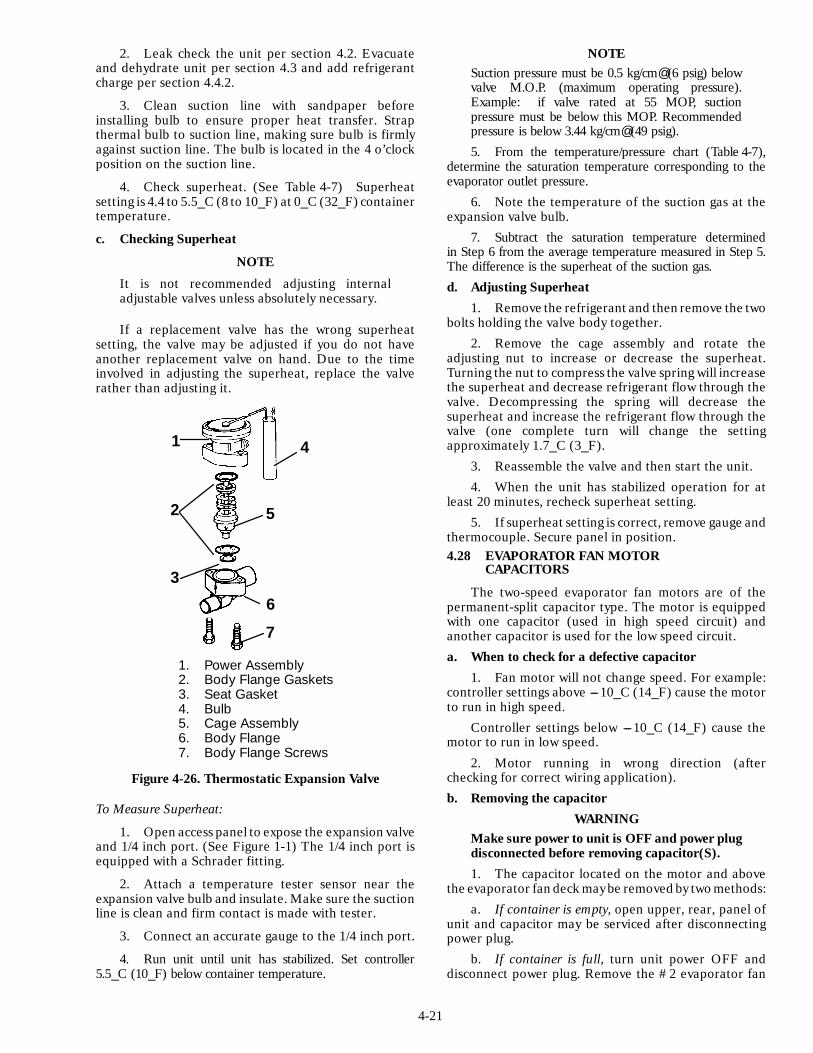
4-21
2. Leak check the unit per section 4.2. Evacuateand dehydrate unit per section 4.3 and add refrigerantcharge per section 4.4.2.
3. Clean suction line with sandpaper beforeinstalling bulb to ensure proper heat transfer. Strapthermal bulb to suction line, making sure bulb is firmlyagainst suction line. The bulb is located in the 4 o’clockposition on the suction line.
4. Check superheat. (See Table 4-7) Superheatsetting is 4.4 to 5.5_C (8 to 10_F) at 0_C (32_F) containertemperature.
c. Checking Superheat
NOTE
It is not recommended adjusting internaladjustable valves unless absolutely necessary.
If a replacement valve has the wrong superheatsetting, the valve may be adjusted if you do not haveanother replacement valve on hand. Due to the timeinvolved in adjusting the superheat, replace the valverather than adjusting it.
6
2 5
3
7
1 4
1. Power Assembly2. Body Flange Gaskets3. Seat Gasket4. Bulb5. Cage Assembly6. Body Flange7. Body Flange Screws
Figure 4-26. Thermostatic Expansion Valve
To Measure Superheat:
1. Open access panel to expose the expansion valveand 1/4 inch port. (See Figure 1-1) The 1/4 inch port isequipped with a Schrader fitting.
2. Attach a temperature tester sensor near theexpansion valve bulb and insulate. Make sure the suctionline is clean and firm contact is made with tester.
3. Connect an accurate gauge to the 1/4 inch port.
4. Run unit until unit has stabilized. Set controller5.5_C (10_F) below container temperature.
NOTESuction pressure must be 0.5 kg/cm@ (6 psig) belowvalve M.O.P. (maximum operating pressure).Example: if valve rated at 55 MOP, suctionpressure must be below this MOP. Recommendedpressure is below 3.44 kg/cm@ (49 psig).5. From the temperature/pressure chart (Table 4-7),
determine the saturation temperature corresponding to theevaporator outlet pressure.
6. Note the temperature of the suction gas at theexpansion valve bulb.
7. Subtract the saturation temperature determinedin Step 6 from the average temperature measured in Step 5.The difference is the superheat of the suction gas.d. Adjusting Superheat
1. Remove the refrigerant and then remove the twobolts holding the valve body together.
2. Remove the cage assembly and rotate theadjusting nut to increase or decrease the superheat.Turning the nut to compress the valve spring will increasethe superheat and decrease refrigerant flow through thevalve. Decompressing the spring will decrease thesuperheat and increase the refrigerant flow through thevalve (one complete turn will change the settingapproximately 1.7_C (3_F).
3. Reassemble the valve and then start the unit.4. When the unit has stabilized operation for at
least 20 minutes, recheck superheat setting.5. If superheat setting is correct, remove gauge and
thermocouple. Secure panel in position.4.28 EVAPORATOR FAN MOTOR
CAPACITORS
The two-speed evaporator fan motors are of thepermanent-split capacitor type. The motor is equippedwith one capacitor (used in high speed circuit) andanother capacitor is used for the low speed circuit.a. When to check for a defective capacitor
1. Fan motor will not change speed. For example:controller settings above ---10_C (14_F) cause the motorto run in high speed.
Controller settings below ---10_C (14_F) cause themotor to run in low speed.
2. Motor running in wrong direction (afterchecking for correct wiring application).b. Removing the capacitor
WARNINGMake sure power to unit is OFF and power plugdisconnected before removing capacitor(S).1. The capacitor located on the motor and above
the evaporator fan deck may be removed by two methods:a. If container is empty, open upper, rear, panel of
unit and capacitor may be serviced after disconnectingpower plug.
b. If container is full, turn unit power OFF anddisconnect power plug. Remove the #2 evaporator fan
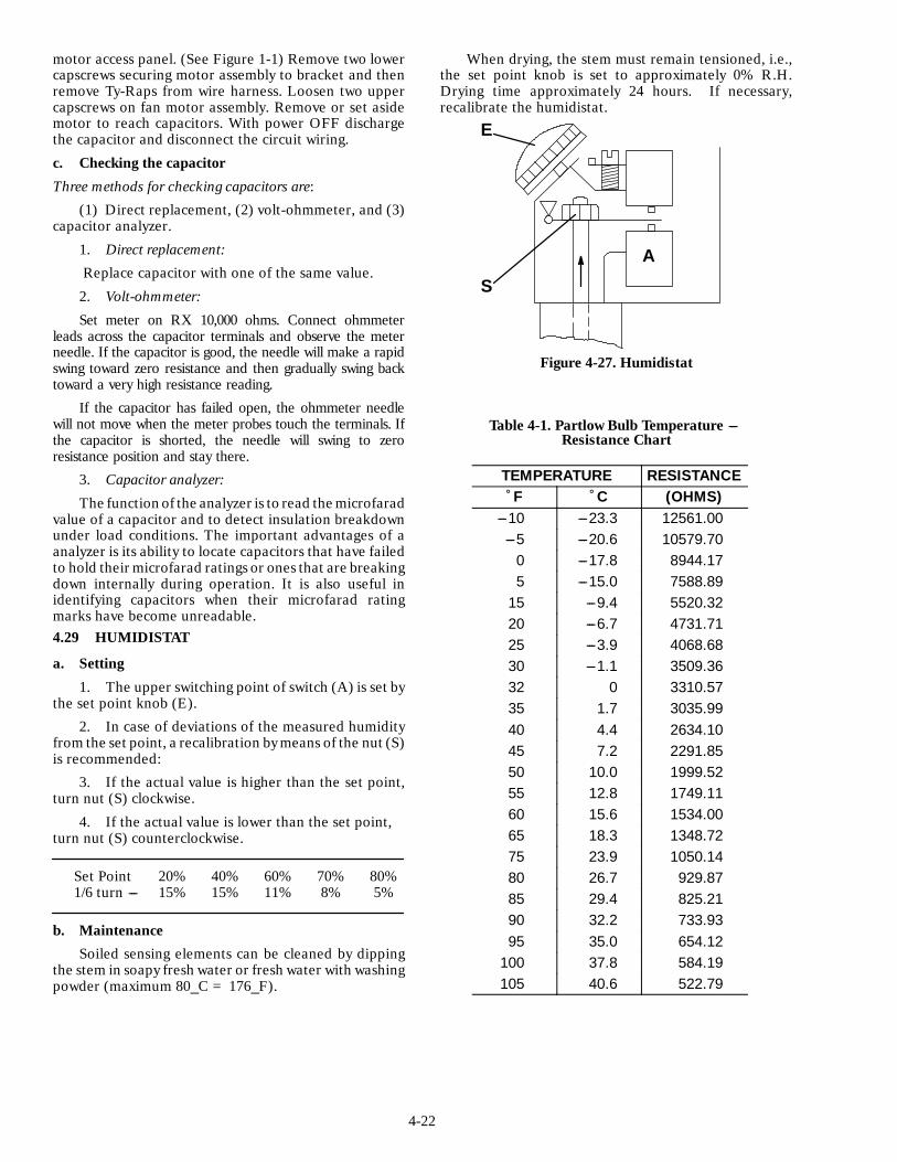
4-22
motor access panel. (See Figure 1-1) Remove two lowercapscrews securing motor assembly to bracket and thenremove Ty-Raps from wire harness. Loosen two uppercapscrews on fan motor assembly. Remove or set asidemotor to reach capacitors. With power OFF dischargethe capacitor and disconnect the circuit wiring.
c. Checking the capacitor
Three methods for checking capacitors are:
(1) Direct replacement, (2) volt-ohmmeter, and (3)capacitor analyzer.
1. Direct replacement:
Replace capacitor with one of the same value.
2. Volt-ohmmeter:
Set meter on RX 10,000 ohms. Connect ohmmeterleads across the capacitor terminals and observe the meterneedle. If the capacitor is good, the needle will make a rapidswing toward zero resistance and then gradually swing backtoward a very high resistance reading.
If the capacitor has failed open, the ohmmeter needlewill not move when the meter probes touch the terminals. Ifthe capacitor is shorted, the needle will swing to zeroresistance position and stay there.
3. Capacitor analyzer:
The function of the analyzer is to read the microfaradvalue of a capacitor and to detect insulation breakdownunder load conditions. The important advantages of aanalyzer is its ability to locate capacitors that have failedto hold their microfarad ratings or ones that are breakingdown internally during operation. It is also useful inidentifying capacitors when their microfarad ratingmarks have become unreadable.4.29 HUMIDISTAT
a. Setting
1. The upper switching point of switch (A) is set bythe set point knob (E).
2. In case of deviations of the measured humidityfrom the set point, a recalibration by means of the nut (S)is recommended:
3. If the actual value is higher than the set point,turn nut (S) clockwise.
4. If the actual value is lower than the set point,turn nut (S) counterclockwise.
Set Point 20% 40% 60% 70% 80%1/6 turn --- 15% 15% 11% 8% 5%
b. Maintenance
Soiled sensing elements can be cleaned by dippingthe stem in soapy fresh water or fresh water with washingpowder (maximum 80_C = 176_F).
When drying, the stem must remain tensioned, i.e.,the set point knob is set to approximately 0% R.H.Drying time approximately 24 hours. If necessary,recalibrate the humidistat.
E
S
A
Figure 4-27. Humidistat
Table 4-1. Partlow Bulb Temperature ---Resistance Chart
TEMPERATURE RESISTANCE˚F ˚C (OHMS)
---10 ---23.3 12561.00---5 ---20.6 10579.70
0 ---17.8 8944.175 ---15.0 7588.89
15 ---9.4 5520.3220 ---6.7 4731.7125 ---3.9 4068.6830 ---1.1 3509.3632 0 3310.5735 1.7 3035.9940 4.4 2634.1045 7.2 2291.8550 10.0 1999.5255 12.8 1749.1160 15.6 1534.0065 18.3 1348.7275 23.9 1050.1480 26.7 929.8785 29.4 825.2190 32.2 733.9395 35.0 654.12
100 37.8 584.19105 40.6 522.79
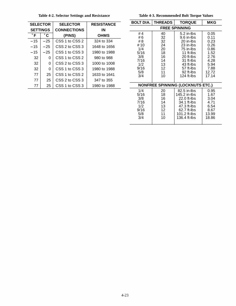
4-23
Table 4-2. Selector Settings and Resistance
SELECTOR SELECTOR RESISTANCESETTINGS CONNECTIONS IN˚F ˚C (PINS) OHMS
---15 ---25 CSS 1 to CSS 2 324 to 334---15 ---25 CSS 2 to CSS 3 1648 to 1656---15 ---25 CSS 1 to CSS 3 1980 to 1988
32 0 CSS 1 to CSS 2 980 to 98832 0 CSS 2 to CSS 3 1000 to 100832 0 CSS 1 to CSS 3 1980 to 198877 25 CSS 1 to CSS 2 1633 to 164177 25 CSS 2 to CSS 3 347 to 35577 25 CSS 1 to CSS 3 1980 to 1988
Table 4-3. Recommended Bolt Torque Values
BOLT DIA. THREADS TORQUE MKGFREE SPINNING
#4#6#8
#101/4
5/163/8
7/161/2
9/165/83/4
403232242018161413121110
5.2 in-lbs9.6 in-lbs20 in-lbs23 in-lbs75 in-lbs11 ft-lbs20 ft-lbs31 ft-lbs43 ft-lbs57 ft-lbs92 ft-lbs
124 ft-lbs
0.050.110.230.260.861.522.764.285.947.88
12.7217.14
NONFREE SPINNING (LOCKNUTS ETC.)1/4
5/163/8
7/161/2
9/165/83/4
2018161413121110
82.5 in-lbs145.2 in-lbs
22.0 ft-lbs34.1 ft-lbs47.3 ft-lbs62.7 ft-lbs
101.2 ft-lbs136.4 ft-lbs
0.951.673.044.716.548.67
13.9918.86
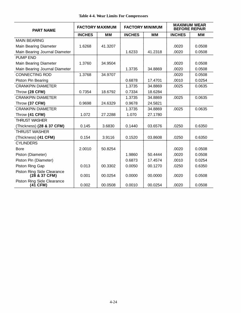
4-24
Table 4-4. Wear Limits For Compressors
FACTORY MAXIMUM FACTORY MINIMUM MAXIMUM WEARPART NAME
FACTORY MAXIMUM FACTORY MINIMUM MAXIMUM WEARBEFORE REPAIRPART NAME
INCHES MM INCHES MM INCHES MMMAIN BEARINGMain Bearing Diameter 1.6268 41.3207 .0020 0.0508Main Bearing Journal Diameter 1.6233 41.2318 .0020 0.0508PUMP ENDMain Bearing Diameter 1.3760 34.9504 .0020 0.0508Main Bearing Journal Diameter 1.3735 34.8869 .0020 0.0508CONNECTING ROD 1.3768 34.9707 .0020 0.0508Piston Pin Bearing 0.6878 17.4701 .0010 0.0254CRANKPIN DIAMETER 1.3735 34.8869 .0025 0.0635Throw (28 CFM) 0.7354 18.6792 0.7334 18.6284CRANKPIN DIAMETER 1.3735 34.8869 .0025 0.0635Throw (37 CFM) 0.9698 24.6329 0.9678 24.5821CRANKPIN DIAMETER 1.3735 34.8869 .0025 0.0635Throw (41 CFM) 1.072 27.2288 1.070 27.1780THRUST WASHER(Thickness) (28 & 37 CFM) 0.145 3.6830 0.1440 03.6576 .0250 0.6350THRUST WASHER(Thickness) (41 CFM) 0.154 3.9116 0.1520 03.8608 .0250 0.6350CYLINDERSBore 2.0010 50.8254 .0020 0.0508Piston (Diameter) 1.9860 50.4444 .0020 0.0508Piston Pin (Diameter) 0.6873 17.4574 .0010 0.0254Piston Ring Gap 0.013 00.3302 0.0050 00.1270 .0250 0.6350Piston Ring Side Clearance
(28 & 37 CFM) 0.001 00.0254 0.0000 00.0000 .0020 0.0508Piston Ring Side Clearance
(41 CFM) 0.002 00.0508 0.0010 00.0254 .0020 0.0508

4-25
Table 4-5. Compressor Torque Values
TORQUE RANGESIZE
TORQUE RANGEUSAGE
DIAMETER THREADSFT LB MKG
USAGE
(INCHES) PER INCHFT-LB MKG
1/16 27 (pipe) 8 --- 12 1.11 --- 1.66 Pipe Plug --- Crankshaft1/8 20 (pipe) 6 --- 10 0.83 --- 1.38 Oil Return Check Valve --- Crankcase1/4 20 (pipe) 20 --- 25 2.77 --- 3.46 Pipe Plug --- Gauge Connection1/4 20 10 --- 12 1.38 --- 1.66 Connecting Rod Capscrew
12 --- 15 1.66 --- 2.07 Baffle Plate --- Crankcase
1/4 2812 --- 16 1.66 --- 2.21 Side Shield
1/4 286 --- 10 0.83 --- 1.38 Oil Pump Drive Segment
12 --- 16 1.66 --- 2.21 Unloader ValveCover Plate --- Plate End
16 --- 20 2.21 --- 2.77 Bearing Head5/16 18
16 20 2.21 2.77Terminal Block Cap Screws5/16 18
20 30 2 77 4 15Suction Valve
20 --- 30 2.77 --- 4.15Discharge ValvePump End Bearing Head
3/8 16 40 --- 50 5.53 --- 6.92 Bottom Plate --- Crankcase Compressor Foot3/8 16 40 50 5.53 6.92Cylinder Head
7/16 14 55 --- 60 7.61 --- 8.30 Motor End Cover --- Crankcase5/8 11 25 --- 30 3.46 --- 4.15 Crankshaft5/8 18 60 --- 75 8.30 --- 10.37 Oil Bypass Plug --- Crankcase#10 32 4 --- 6 0.55 --- 0.83 Oil Pump Drive Segment1-1/2 18 NEF 35 --- 45 4.84 --- 6.22 Oil Level Sight Glass
NEF --- National Extra Fine
Table 4-6. Sensor D.C. Voltages
TEMPERATURE D.C. TEMPERATURE D.C. TEMPERATURE D.C.˚F ˚C VOLTS ˚F ˚C VOLTS ˚F ˚C VOLTS---20 ---28.9 1.57 14 ---10.0 3.45 48 8.9 5.32---18 ---27.8 1.68 16 ---8.9 3.56 50 10.0 5.45---16 ---26.7 1.78 18 ---7.8 3.68 52 11.1 5.55---14 ---25.6 1.90 20 ---6.7 3.79 54 12.2 5.67---12 ---24.4 2.00 22 ---5.5 3.90 56 13.3 5.78---10 ---23.3 2.10 24 ---4.4 4.00 58 14.4 5.88---8 ---22.2 2.22 26 ---3.3 4.10 60 15.6 5.98---6 ---21.1 2.32 28 ---2.2 4.22 62 16.7 6.10---4 ---20.0 2.44 30 ---1.1 4.32 64 17.8 6.20---2 ---18.9 2.55 32 0 4.45 66 18.9 6.32
0 ---17.8 2.70 34 1.1 4.55 68 20.0 6.422 ---16.7 2.80 36 2.2 4.68 70 21.1 6.554 ---15.6 2.90 38 3.3 4.78 72 22.2 6.656 ---14.4 3.00 40 4.4 4.88 74 23.3 6.778 ---13.3 3.10 42 5.5 5.00 76 24.4 6.88
10 ---12.2 3.23 44 6.7 5.10 78 25.6 6.9812 ---11.1 3.33 46 7.8 5.22
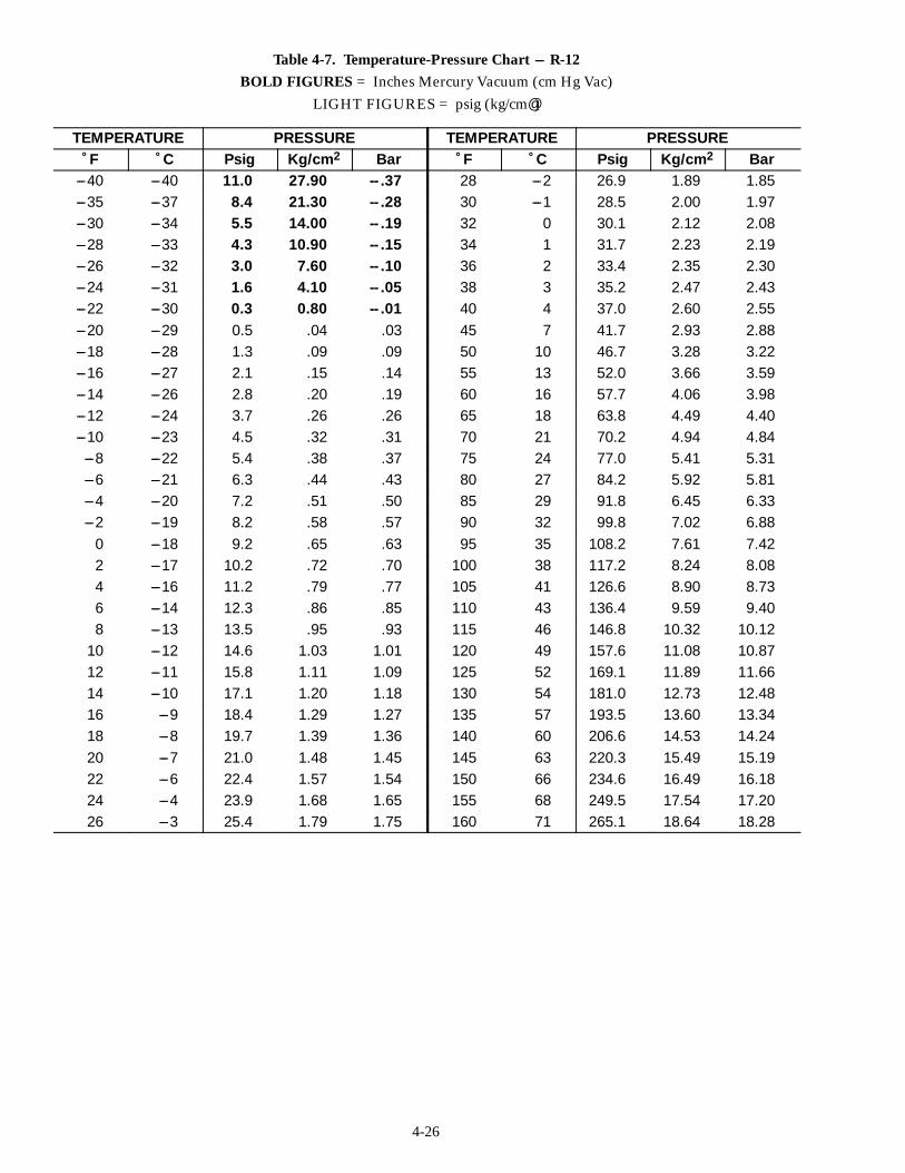
4-26
Table 4-7. Temperature-Pressure Chart --- R-12BOLD FIGURES = Inches Mercury Vacuum (cm Hg Vac)
LIGHT FIGURES = psig (kg/cm@)
TEMPERATURE PRESSURE TEMPERATURE PRESSURE˚F ˚C Psig Kg/cm2 Bar ˚F ˚C Psig Kg/cm2 Bar
---40 ---40 11.0 27.90 -- .37 28 ---2 26.9 1.89 1.85---35 ---37 8.4 21.30 -- .28 30 ---1 28.5 2.00 1.97---30 ---34 5.5 14.00 -- .19 32 0 30.1 2.12 2.08---28 ---33 4.3 10.90 -- .15 34 1 31.7 2.23 2.19---26 ---32 3.0 7.60 -- .10 36 2 33.4 2.35 2.30---24 ---31 1.6 4.10 -- .05 38 3 35.2 2.47 2.43---22 ---30 0.3 0.80 -- .01 40 4 37.0 2.60 2.55---20 ---29 0.5 .04 .03 45 7 41.7 2.93 2.88---18 ---28 1.3 .09 .09 50 10 46.7 3.28 3.22---16 ---27 2.1 .15 .14 55 13 52.0 3.66 3.59---14 ---26 2.8 .20 .19 60 16 57.7 4.06 3.98---12 ---24 3.7 .26 .26 65 18 63.8 4.49 4.40---10 ---23 4.5 .32 .31 70 21 70.2 4.94 4.84---8 ---22 5.4 .38 .37 75 24 77.0 5.41 5.31---6 ---21 6.3 .44 .43 80 27 84.2 5.92 5.81---4 ---20 7.2 .51 .50 85 29 91.8 6.45 6.33---2 ---19 8.2 .58 .57 90 32 99.8 7.02 6.88
0 ---18 9.2 .65 .63 95 35 108.2 7.61 7.422 ---17 10.2 .72 .70 100 38 117.2 8.24 8.084 ---16 11.2 .79 .77 105 41 126.6 8.90 8.736 ---14 12.3 .86 .85 110 43 136.4 9.59 9.408 ---13 13.5 .95 .93 115 46 146.8 10.32 10.12
10 ---12 14.6 1.03 1.01 120 49 157.6 11.08 10.8712 ---11 15.8 1.11 1.09 125 52 169.1 11.89 11.6614 ---10 17.1 1.20 1.18 130 54 181.0 12.73 12.4816 ---9 18.4 1.29 1.27 135 57 193.5 13.60 13.3418 ---8 19.7 1.39 1.36 140 60 206.6 14.53 14.2420 ---7 21.0 1.48 1.45 145 63 220.3 15.49 15.1922 ---6 22.4 1.57 1.54 150 66 234.6 16.49 16.1824 ---4 23.9 1.68 1.65 155 68 249.5 17.54 17.2026 ---3 25.4 1.79 1.75 160 71 265.1 18.64 18.28
5-1
SECTION 5
ELECTRICAL WIRING SCHEMATIC AND DIAGRAMS
5.1 INTRODUCTION
This section contains Electrical Wiring Schematics and Diagrams covering the Models listed in Table 1-1. Thefollowing general safety notices supplement the specificwarnings and cautions appearingelsewhere in this manual. Theyare recommeded precautions that must be understood and applied during operation and maintenance of the equipmentcovered herein.
WARNING
Beware of unannounced starting of the evaporator and condenser fans. Do not open condenser fan grille beforeturning power OFF and disconnecting power plug.
WARNING
Do not attempt to remove power plug(s) before turning OFF start-stop switch (ST), unit circuit breaker(s) andexternal power source.
Make sure the power plugs are clean and dry before connecting to any power receptacle.
WARNING
Do not use a nitrogen cylinder without a pressure regulator because cylinder pressure is approximately 165kg/cm@ (2350 psi). Do not use oxygen in or near a refrigeration system as an explosion may occur.
WARNING
Make sure power to unit is OFF and power plug disconnected before removing capacitor(S).
CAUTION
Make sure that the unit circuit breaker(s) (CB) and the start-stop switch are in the OFF position beforeconnecting to any electrical power source.

5-2
Figure 5-1. Electrical Wiring Schematic --- Model 69NT20-284(Sheet 1 of 2)
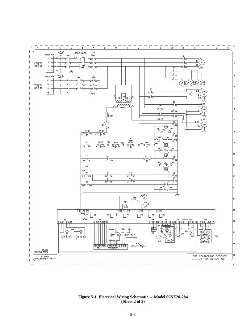
5-3
Figure 5-1. Electrical Wiring Schematic --- Model 69NT20-284(Sheet 2 of 2)

5-4
Figure 5-2. Electrical Wiring Diagram --- Model 69NT20-284(Sheet 1 of 2)
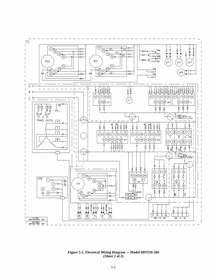
5-5
Figure 5-2. Electrical Wiring Diagram --- Model 69NT20-284(Sheet 2 of 2)
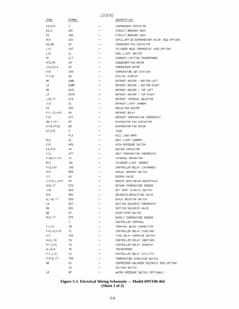
5-6
Figure 5-3. Electrical Wiring Schematic --- Model 69NT40-464(Sheet 1 of 2)
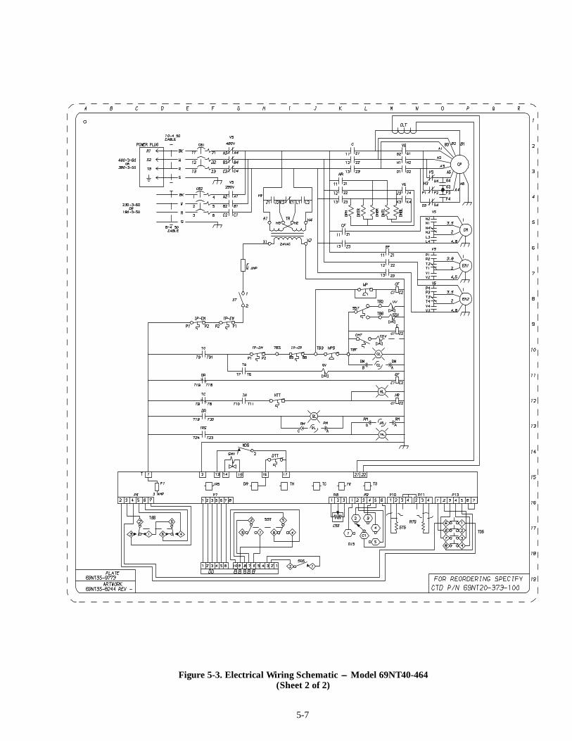
5-7
Figure 5-3. Electrical Wiring Schematic --- Model 69NT40-464(Sheet 2 of 2)
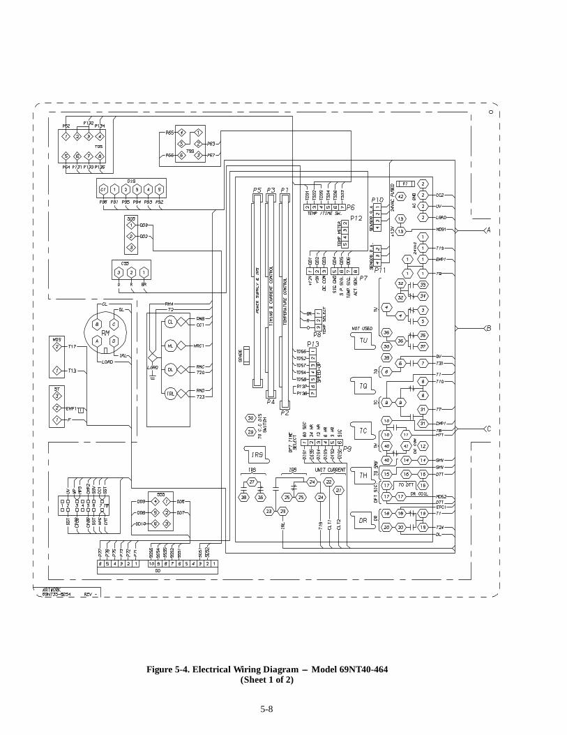
5-8
Figure 5-4. Electrical Wiring Diagram --- Model 69NT40-464(Sheet 1 of 2)

5-9
Figure 5-4. Electrical Wiring Diagram --- Model 69NT40-464(Sheet 2 of 2)
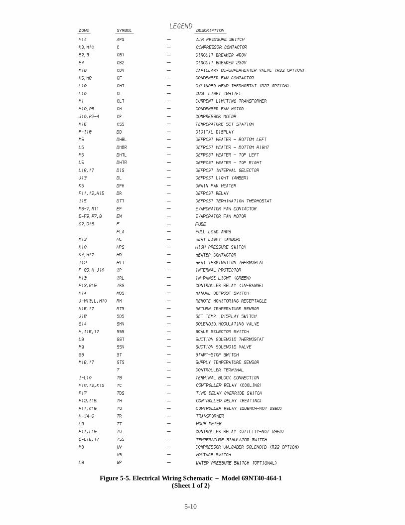
5-10
Figure 5-5. Electrical Wiring Schematic --- Model 69NT40-464-1(Sheet 1 of 2)

5-11
Figure 5-5. Electrical Wiring Schematic --- Model 69NT40-464-1(Sheet 2 of 2)
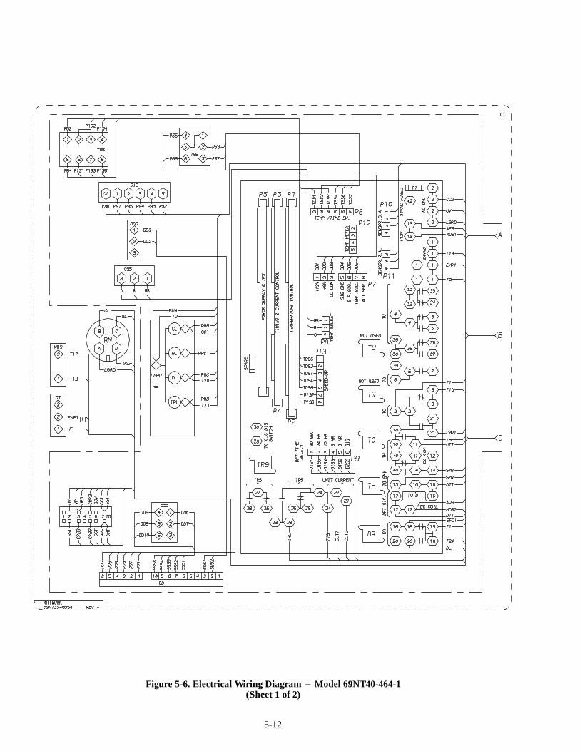
5-12
Figure 5-6. Electrical Wiring Diagram --- Model 69NT40-464-1(Sheet 1 of 2)

5-13
Figure 5-6. Electrical Wiring Diagram --- Model 69NT40-464-1(Sheet 2 of 2)
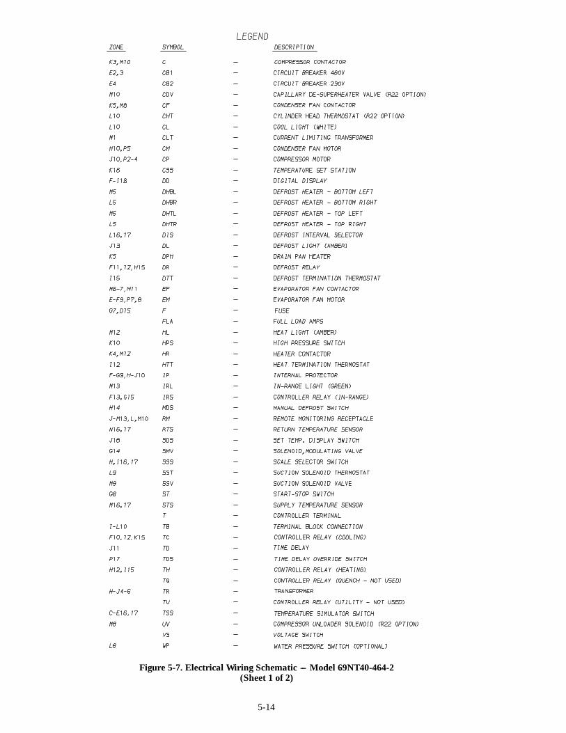
5-14
Figure 5-7. Electrical Wiring Schematic --- Model 69NT40-464-2(Sheet 1 of 2)
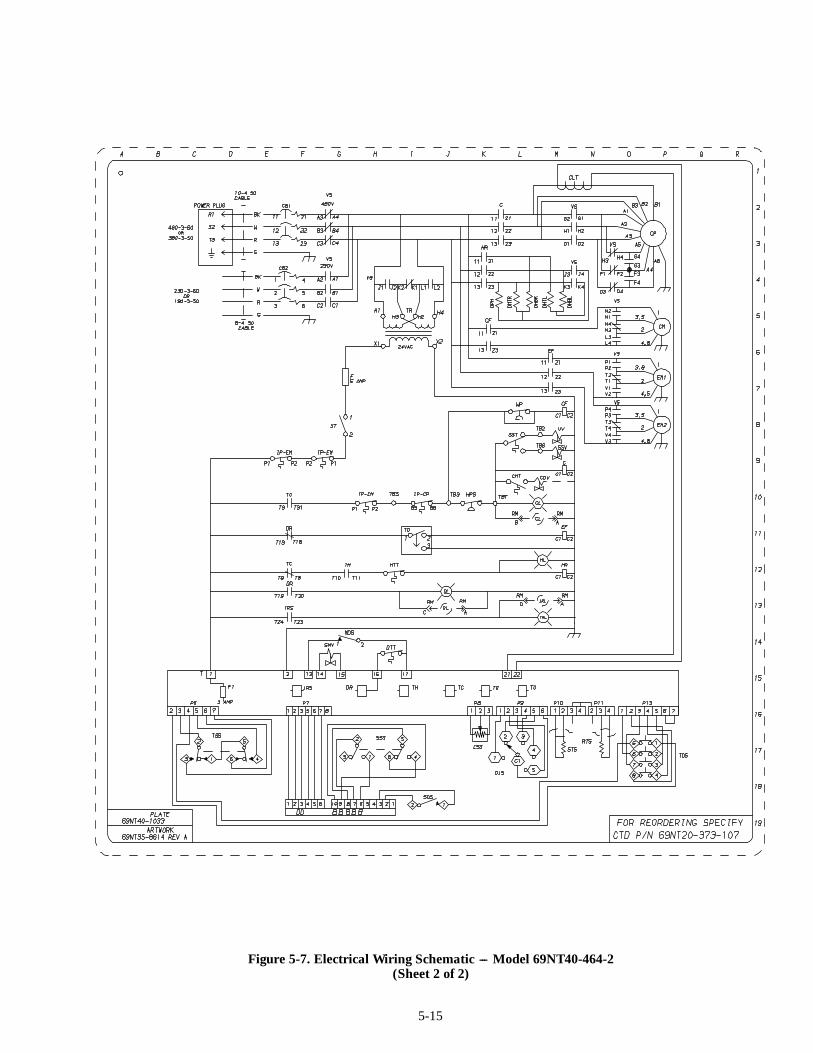
5-15
Figure 5-7. Electrical Wiring Schematic --- Model 69NT40-464-2(Sheet 2 of 2)
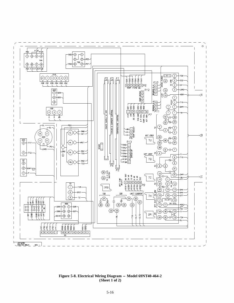
5-16
Figure 5-8. Electrical Wiring Diagram --- Model 69NT40-464-2(Sheet 1 of 2)
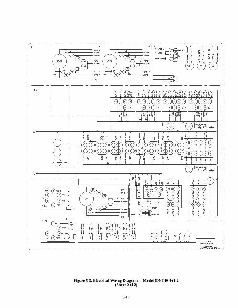
5-17
Figure 5-8. Electrical Wiring Diagram --- Model 69NT40-464-2(Sheet 2 of 2)
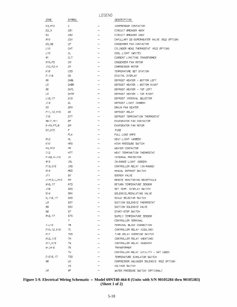
5-18
Figure 5-9. Electrical Wiring Schematic --- Model 69NT40-464-8 (Units with S/N 90105284 thru 90105383)(Sheet 1 of 2)

5-19
Figure 5-9. Electrical Wiring Schematic --- Model 69NT40-464-8 (Units with S/N 90105284 thru 90105383)(Sheet 2 of 2)

5-20
Figure 5-10. Electrical Wiring Diagram --- Model 69NT40-464-8 (Units with S/N 90105284 thru 90105383)(Sheet 1 of 2)

5-21
Figure 5-10. Electrical Wiring Diagram --- Model 69NT40-464-8 (Units with S/N 90105284 thru 90105383)(Sheet 2 of 2)
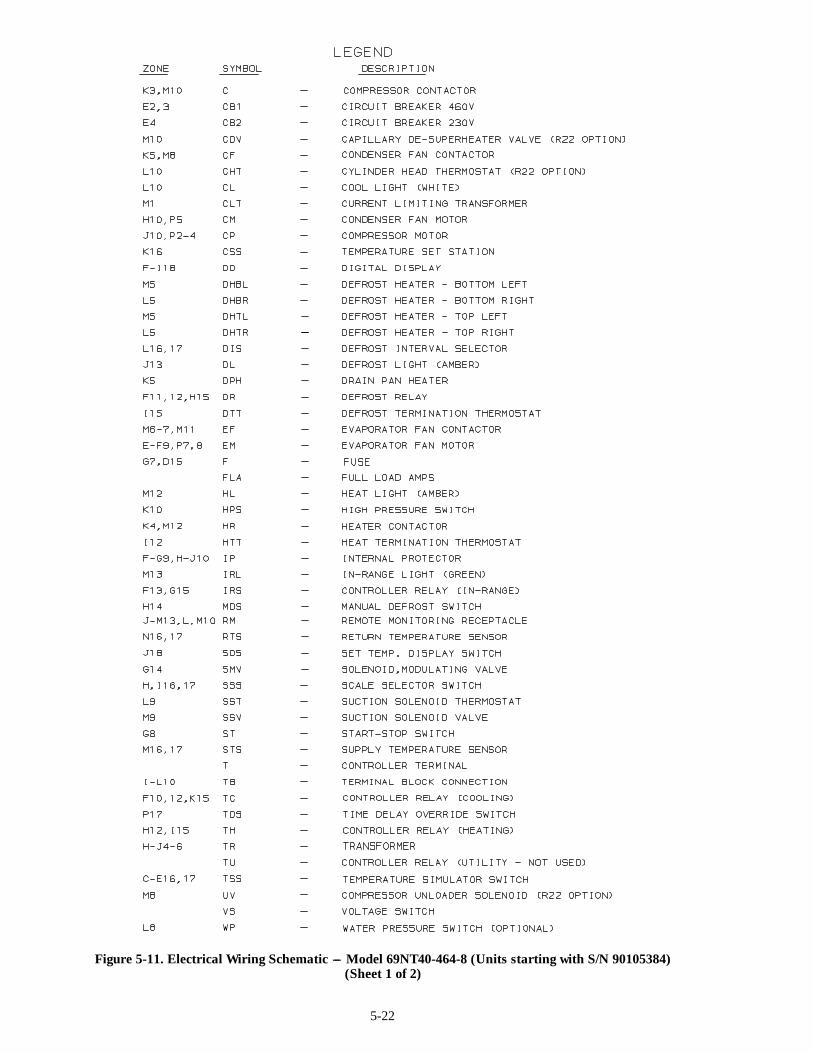
5-22
Figure 5-11. Electrical Wiring Schematic --- Model 69NT40-464-8 (Units starting with S/N 90105384)(Sheet 1 of 2)
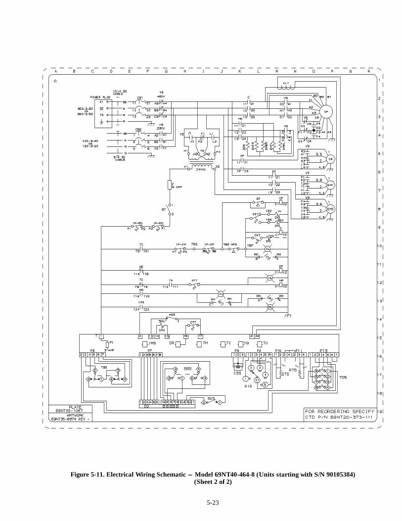
5-23
Figure 5-11. Electrical Wiring Schematic --- Model 69NT40-464-8 (Units starting with S/N 90105384)(Sheet 2 of 2)

5-24
Figure 5-12. Electrical Wiring Diagram --- Model 69NT40-464-8 (Units starting with S/N 90105384)(Sheet 1 of 2)
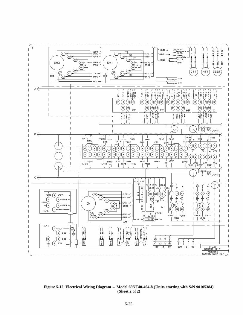
5-25
Figure 5-12. Electrical Wiring Diagram --- Model 69NT40-464-8 (Units starting with S/N 90105384)(Sheet 2 of 2)
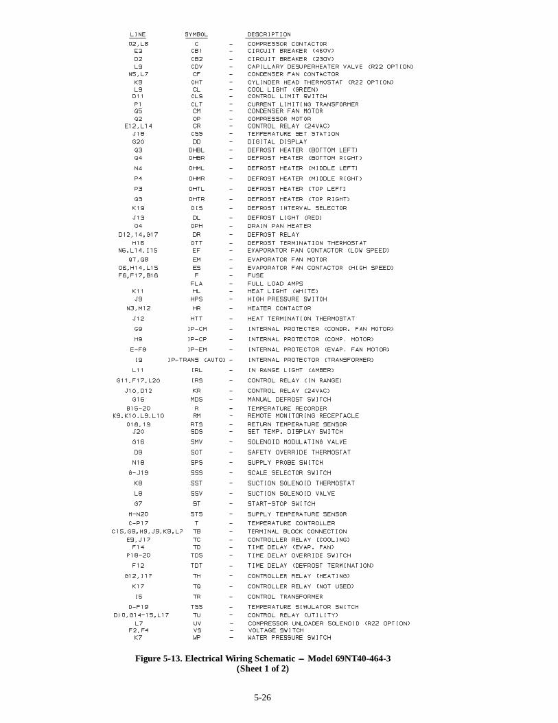
5-26
Figure 5-13. Electrical Wiring Schematic --- Model 69NT40-464-3(Sheet 1 of 2)
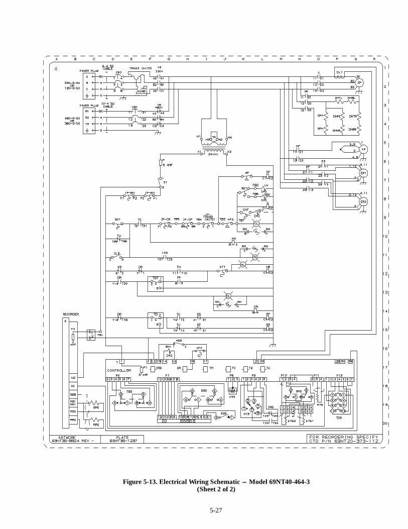
5-27
Figure 5-13. Electrical Wiring Schematic --- Model 69NT40-464-3(Sheet 2 of 2)

5-28
Figure 5-14. Electrical Wiring Diagram --- Model 69NT40-464-3(Sheet 1 of 2)
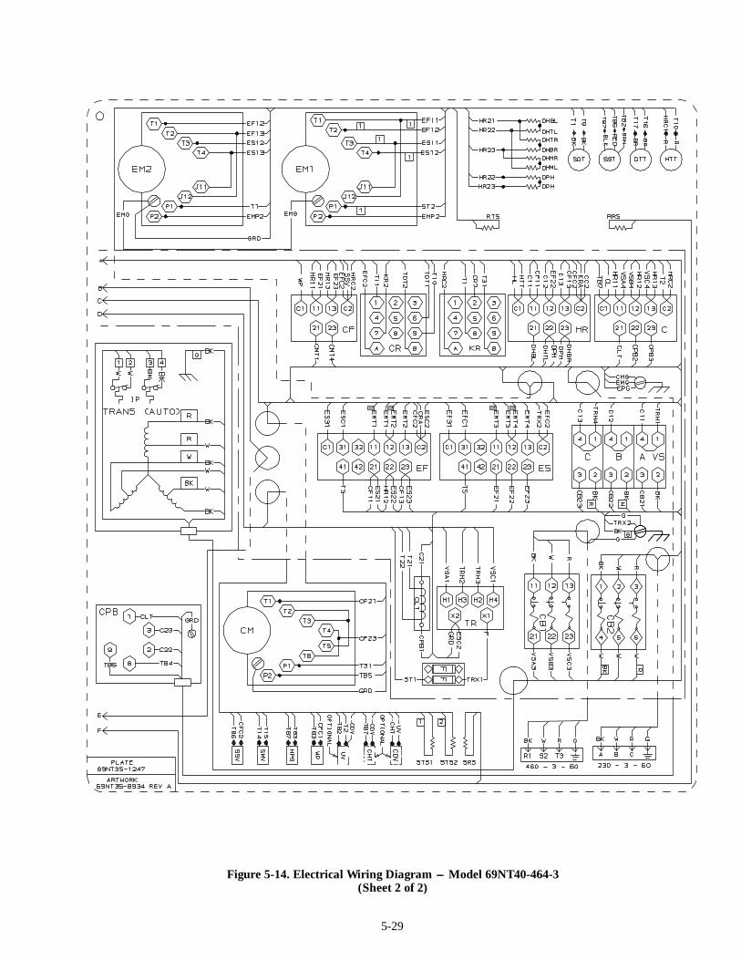
5-29
Figure 5-14. Electrical Wiring Diagram --- Model 69NT40-464-3(Sheet 2 of 2)
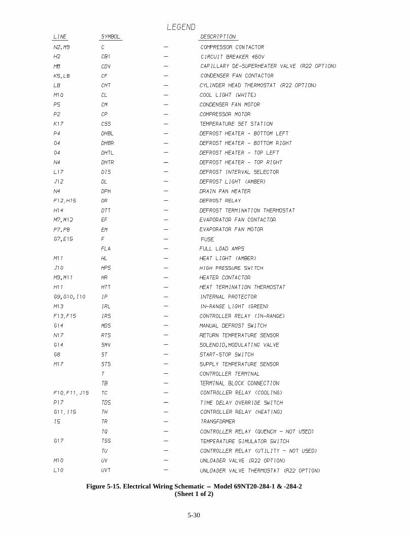
5-30
Figure 5-15. Electrical Wiring Schematic --- Model 69NT20-284-1 & -284-2(Sheet 1 of 2)
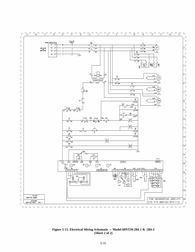
5-31
Figure 5-15. Electrical Wiring Schematic --- Model 69NT20-284-1 & -284-2(Sheet 2 of 2)

5-32
Figure 5-16. Electrical Wiring Diagram --- Model 69NT20-284-1 & -284-2(Sheet 1 of 2)
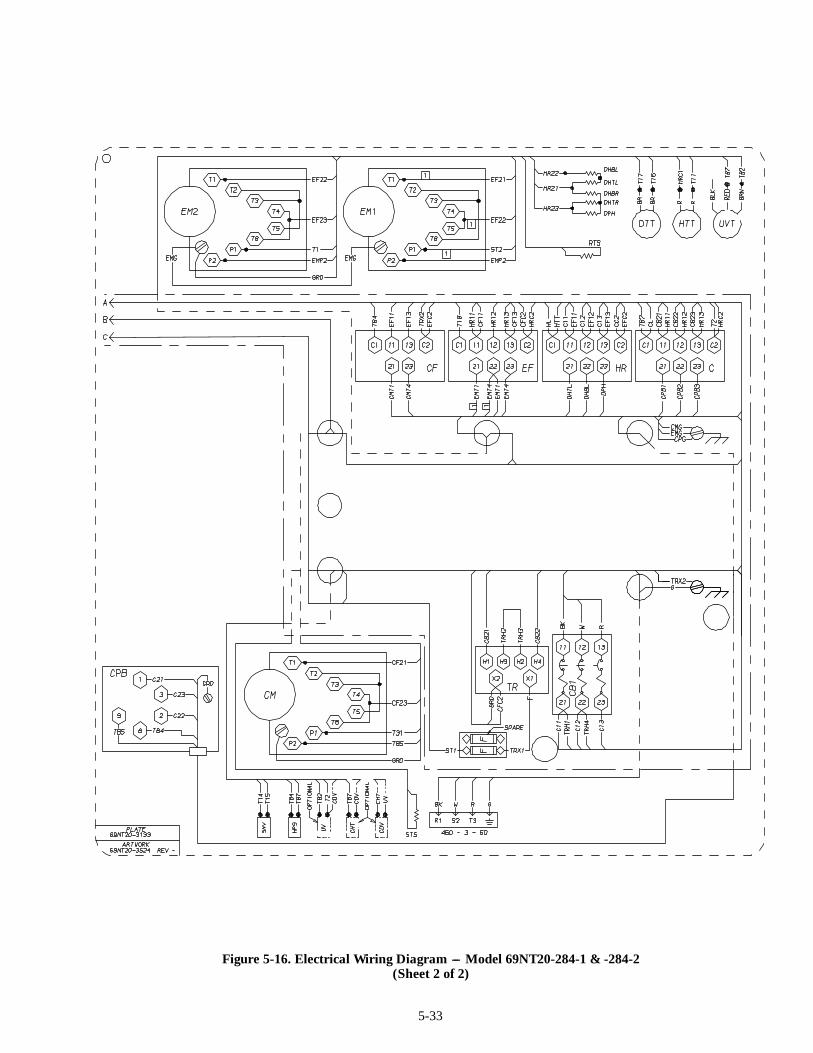
5-33
Figure 5-16. Electrical Wiring Diagram --- Model 69NT20-284-1 & -284-2(Sheet 2 of 2)
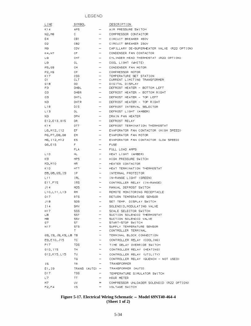
5-34
Figure 5-17. Electrical Wiring Schematic --- Model 69NT40-464-4(Sheet 1 of 2)

5-35
Figure 5-17. Electrical Wiring Schematic --- Model 69NT40-464-4(Sheet 2 of 2)
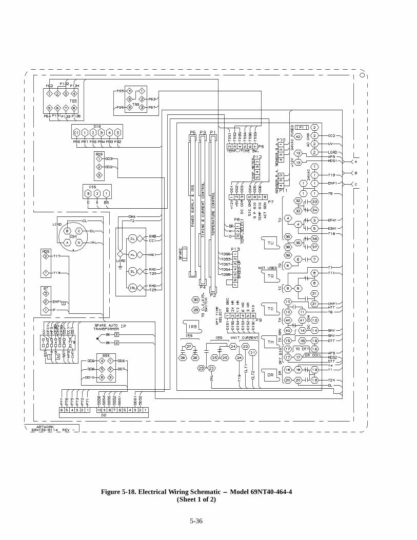
5-36
Figure 5-18. Electrical Wiring Schematic --- Model 69NT40-464-4(Sheet 1 of 2)
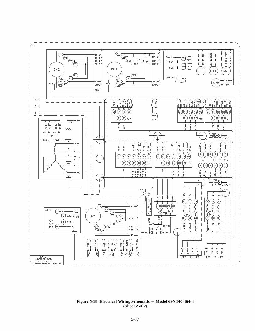
5-37
Figure 5-18. Electrical Wiring Schematic --- Model 69NT40-464-4(Sheet 2 of 2)
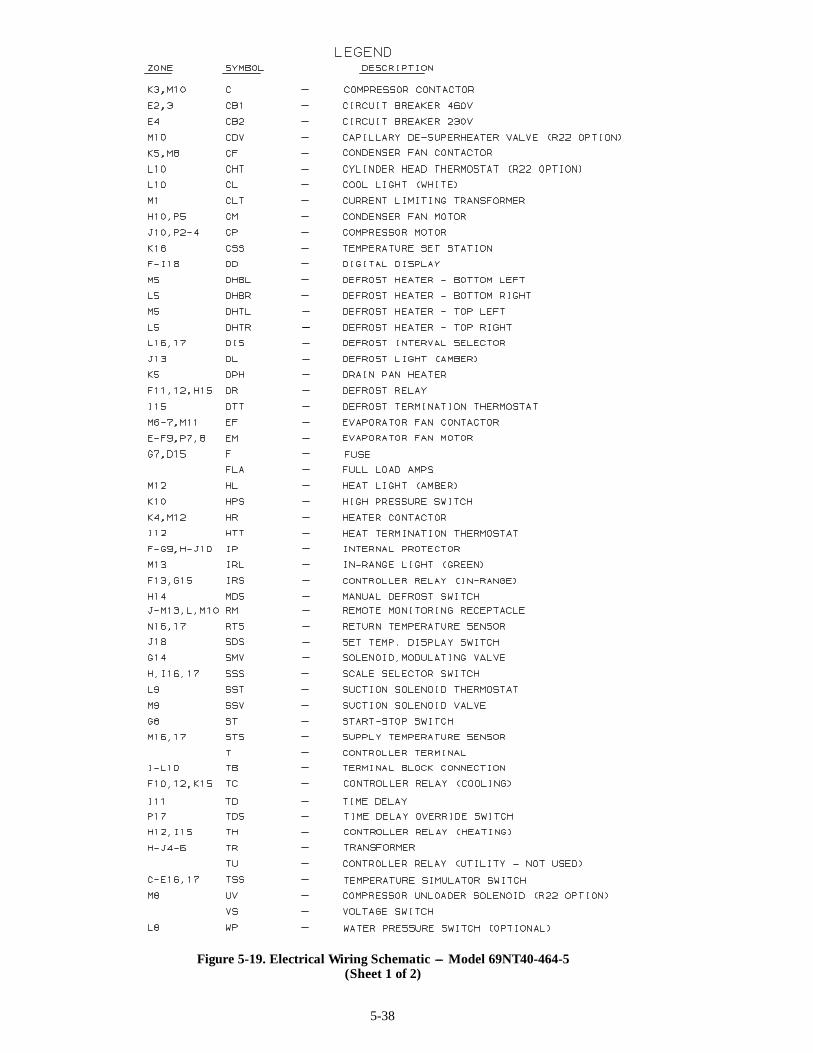
5-38
Figure 5-19. Electrical Wiring Schematic --- Model 69NT40-464-5(Sheet 1 of 2)

5-39
Figure 5-19. Electrical Wiring Schematic --- Model 69NT40-464-5(Sheet 2 of 2)

5-40
Figure 5-20. Electrical Wiring Schematic --- Model 69NT40-464-5(Sheet 1 of 2)

5-41
Figure 5-20. Electrical Wiring Schematic --- Model 69NT40-464-5(Sheet 2 of 2)
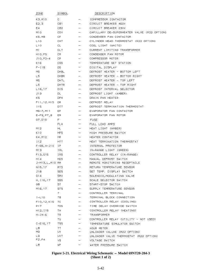
5-42
Figure 5-21. Electrical Wiring Schematic --- Model 69NT20-284-3(Sheet 1 of 2)

5-43
Figure 5-21. Electrical Wiring Schematic --- Model 69NT20-284-3(Sheet 2 of 2)
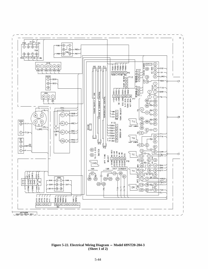
5-44
Figure 5-22. Electrical Wiring Diagram --- Model 69NT20-284-3(Sheet 1 of 2)
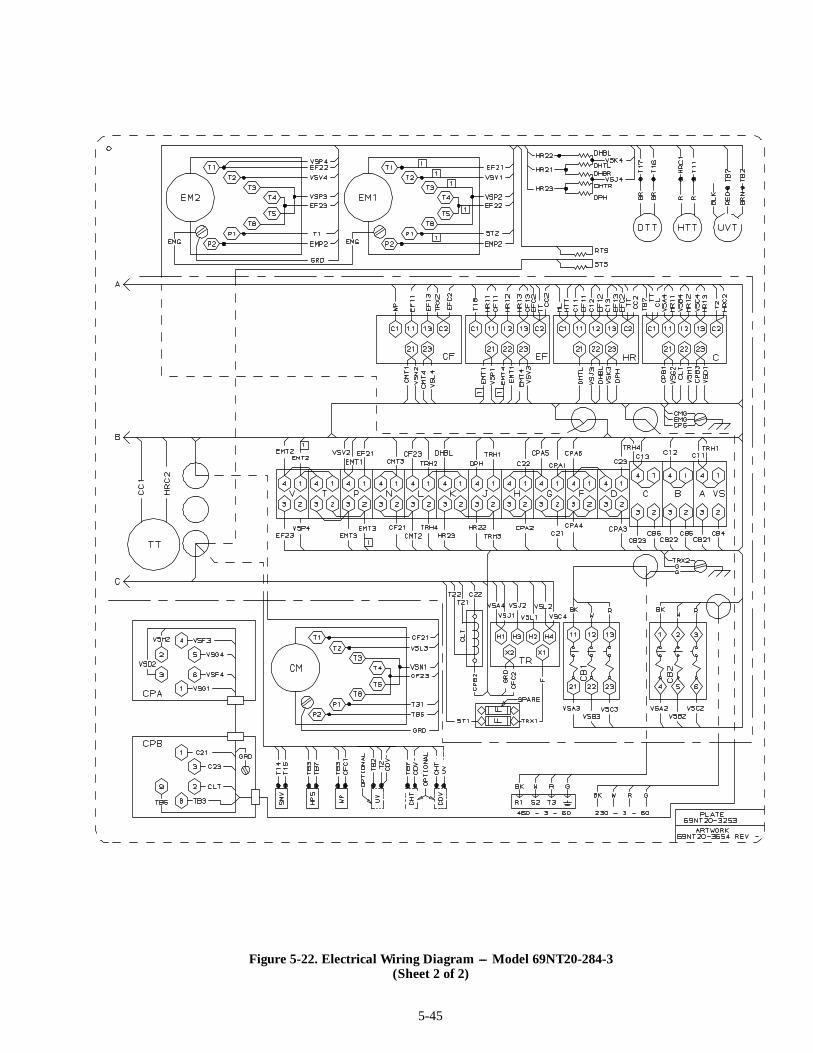
5-45
Figure 5-22. Electrical Wiring Diagram --- Model 69NT20-284-3(Sheet 2 of 2)
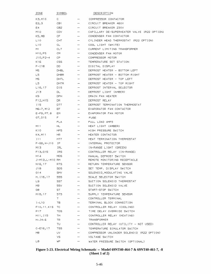
5-46
Figure 5-23. Electrical Wiring Schematic --- Model 69NT40-464-7 & 69NT40-461-7, -8(Sheet 1 of 2)
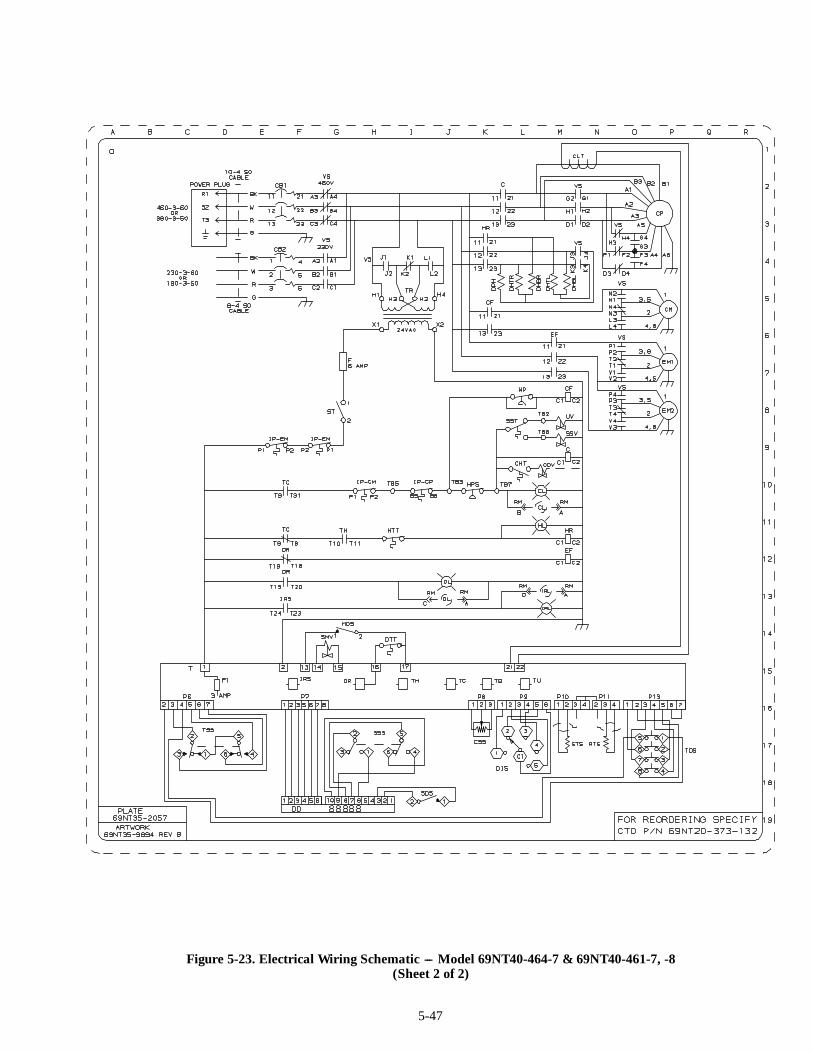
5-47
Figure 5-23. Electrical Wiring Schematic --- Model 69NT40-464-7 & 69NT40-461-7, -8(Sheet 2 of 2)

5-48
Figure 5-24. Electrical Wiring Diagram --- Model 69NT40-464-7 & 69NT40-461-7, -8(Sheet 1 of 2)

5-49
Figure 5-24. Electrical Wiring Diagram --- Model 69NT40-464-7 & 69NT40-461-7, -8(Sheet 2 of 2)
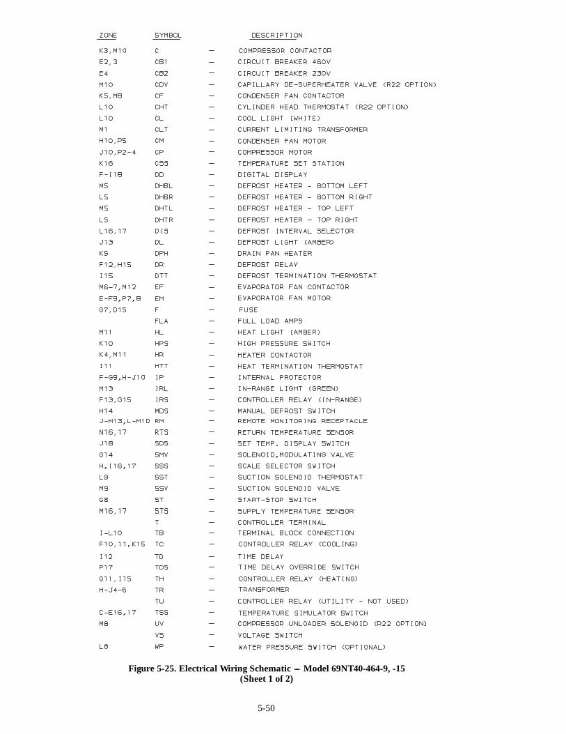
5-50
Figure 5-25. Electrical Wiring Schematic --- Model 69NT40-464-9, -15(Sheet 1 of 2)

5-51
Figure 5-25. Electrical Wiring Schematic --- Model 69NT40-464-9, -15(Sheet 2 of 2)
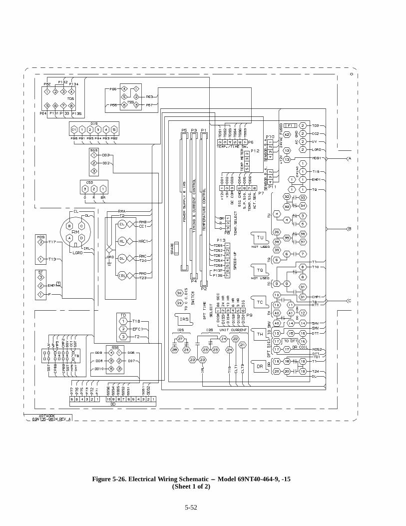
5-52
Figure 5-26. Electrical Wiring Schematic --- Model 69NT40-464-9, -15(Sheet 1 of 2)
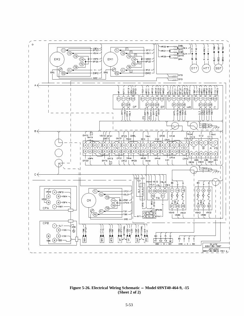
5-53
Figure 5-26. Electrical Wiring Schematic --- Model 69NT40-464-9, -15(Sheet 2 of 2)
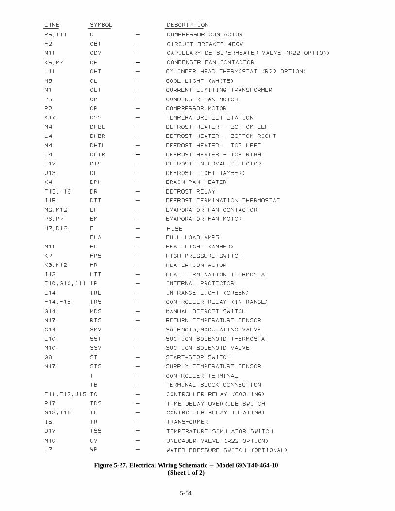
5-54
Figure 5-27. Electrical Wiring Schematic --- Model 69NT40-464-10(Sheet 1 of 2)
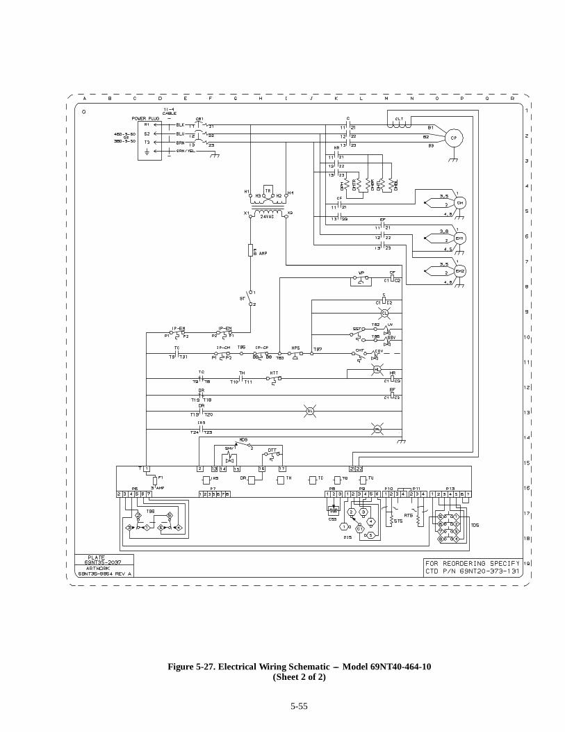
5-55
Figure 5-27. Electrical Wiring Schematic --- Model 69NT40-464-10(Sheet 2 of 2)

5-56
Figure 5-28. Electrical Wiring Schematic --- Model 69NT40-464-10(Sheet 1 of 2)

5-57
Figure 5-28. Electrical Wiring Schematic --- Model 69NT40-464-10(Sheet 2 of 2)
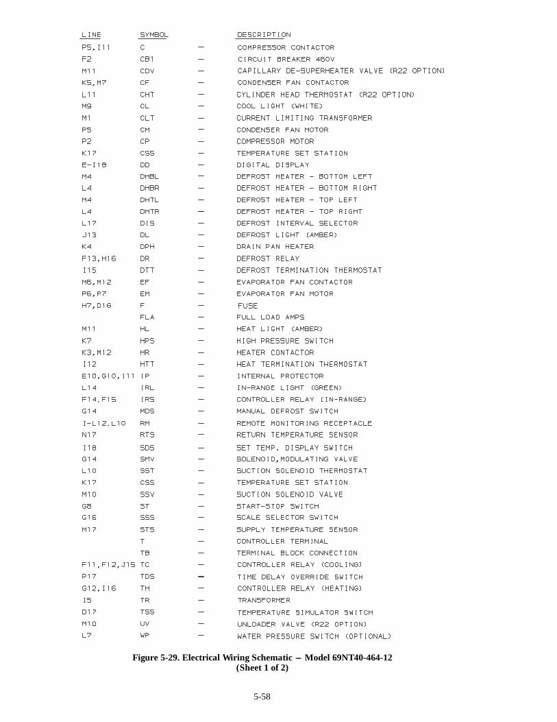
5-58
Figure 5-29. Electrical Wiring Schematic --- Model 69NT40-464-12(Sheet 1 of 2)

5-59
Figure 5-29. Electrical Wiring Schematic --- Model 69NT40-464-12(Sheet 2 of 2)
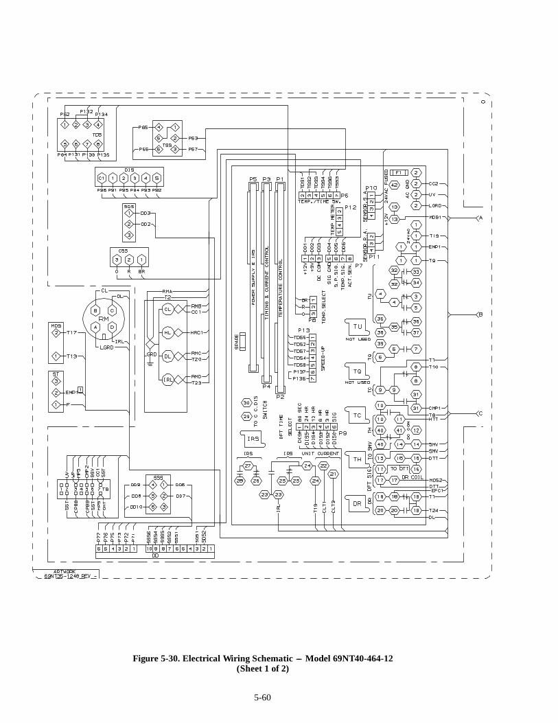
5-60
Figure 5-30. Electrical Wiring Schematic --- Model 69NT40-464-12(Sheet 1 of 2)
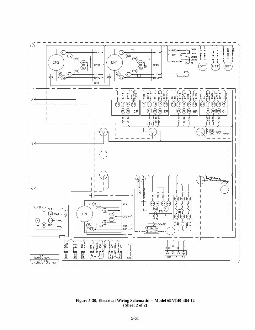
5-61
Figure 5-30. Electrical Wiring Schematic --- Model 69NT40-464-12(Sheet 2 of 2)