Modelling of the Toyota Estima MPV 2.416v Hybridalexandria.tue.nl/repository/books/626038.pdf ·...
31
Modelling of the Toyota Estima MPV 2.416v Hybrid P.EM. Noben OCT 2004.91 Traineeship report Coach(es): dr. ir. Alex Serrarens dr. ir. Igo Besselink Supervisor: prof. ir. N.J.J. Liebrand Technische Universiteit Eindhoven Department Mechanical Engineering Dynamics and Control Technology Group Eindhoven, August, 2004
Transcript of Modelling of the Toyota Estima MPV 2.416v Hybridalexandria.tue.nl/repository/books/626038.pdf ·...

Modelling of the Toyota EstimaMPV 2.416v Hybrid
P.EM. Noben
OCT 2004.91
Traineeship report
Coach(es): dr. ir. Alex Serrarensdr. ir. Igo Besselink
Supervisor: prof. ir. N.J.J. Liebrand
Technische Universiteit EindhovenDepartment Mechanical EngineeringDynamics and Control Technology Group
Eindhoven, August, 2004

Abstract
The Toyota Motor Company developed the Toyota Estima Hybrid which is equipped with the ToyotaHybrid System-CVT (THS-C). In this report the THS-C will be investigated and a model is derived.This model is implemented in Matlab Simulink and some driving modes are simulated. This modelis made to be implemented in ADVANCE, a coupled vehicle dynamics and power train simulationsprogram developed by TNO, which will be done in future research.
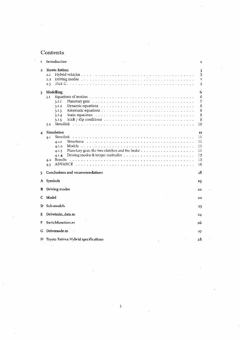
Contents
I Introduction
2 Toyota Estima2.1 Hybrid vehicles .2.2 Driving modes2.3 THS-C.
3 Modellingp Equations ofmotion
p.I Planetary gear . . .3.1.2 Dynamic equations3.1.3 Kinematic equations.3.1.4 Static equations ...P·5 Stick I slip conditions
3.2 Simulink . . . . . . . . . . .
4 Simulation4.1 Simulink
4.I.I Structures4.1.2 Models ..4.1.3 Planetary gear, the two clutches and the brake .4.1.4 Driving modes & torque con:troller
4.2 Results ..4.3 ADVANCE .
5 Conclusions and recommendations
A Symbols
B Driving modes
C Model
D Sub-models
E Drivetrain_data.m
F Switchfunction.m
G Drivemode;m
H Toyota Estima Hybrid specifications
1
2
3345
6678889
10
II
11111111121216
18
20
22
26
28

1 Introduction
Toyota Motor Corporation developed the Toyota Hybrid System-CVT (THS-C) for mini-vans. In thisreport some dynamic aspects of the THS-C will be further investigated. The primary goal is to makea model of the Toyota Estima Hybrid in ADVANCE, a coupled vehicle dynamics and power train simulation program developed by TNO. Simulation of the power train using Simulink is performed andthe results are evaluated.
First a study is preformed to make a model of the THS-C, which is in fact the front drive of theToyota Estima. The THS-C is based on the Super CVT (Kno) [7], but the conventional torque converter is replaced by a torsional damper and a new developed motor-generator. For smooth switchingbetween the different driving modes it mal<es use ofwet multiple disc clutches. The Toyota Estima isalso equipped with a motor-generator which drives the rear wheels for optimal vehicle dynamics andfurther fuel saving. In fact, the powertrain is of a hybrid type. In the simulation study, the dynamicbehavior of the front drive is evaluated and the functionality of the model for further research is discussed.
Chapter 2 explains the Toyota Estima Hybrid in more detail. In particular, the various driving modesand functions of the THS-C are explained..Chapter 3 explains how the mathematical model of thispower train is derived. Chapter 4 explains how the Simulink model is composed, how the simulationswere done and discusses the results. Finally the conclusions and some recommendations for furtherresearch are given in chapter 5.
2

2 Toyota Estima
In June 200r Toyota introduced the Estima Hybrid in Japan, the worlds first hybrid minivan and theworlds first mass produced gasoline/electric hybrid four-wheel drive vehicle. In this section the ToyotaEstima Hybrid will be further investigated.
2.1 Hybrid vehicles
The main idea of a hybrid vehicle is to improve the fuel-efficiency without loosing t..~e main performance and comfort characteristics. Some functions ofhybrid vehicles are, [r]:
1. Energy-loss reduction:Upon certain conditions, the system automatically stops the idling of the engine (idling stop),thus reducing the fuel consumption during vehicle stand-still.
2. Energy recovery and reuse:The energy that would normally be wasted as heat during deceleration and braldng is recoveredas electrical energy, which is used later to power the starter and the electric motor.
3. Motor assist:The electric motor assists the engine during acceleration.
4. High-efficiency operation control:The system maximizes the vehicle's overall efficiency by using the electric motor to run thevehicle under operating conditions in which the engine's efficiency is low and by generatingelectricity under operating conditions in which the engine's efficiency is high.
The parallel hybrid system has all of these characteristics and therefore provides both superior fuelefficiency and driving performance.The Toyota Estima is a parallel hybrid, the Toyota hybrid system with CVT (THS-C) combines a newlydeveloped high efficiency gasoline engine, front motor and CVT transmission. This system has twomotors, and depending on the driving conditions, uses only the electric motor or the driving powerfrom both the electric motor and the engine, in order to achieve the highest efficiency level. Furthermore, when necessary, the system drives the wheels while simultaneously generating electricity usinga generator. In Figure r, the hybrid system can be seen.
Figure 1: THS-C with engine, [9]
3
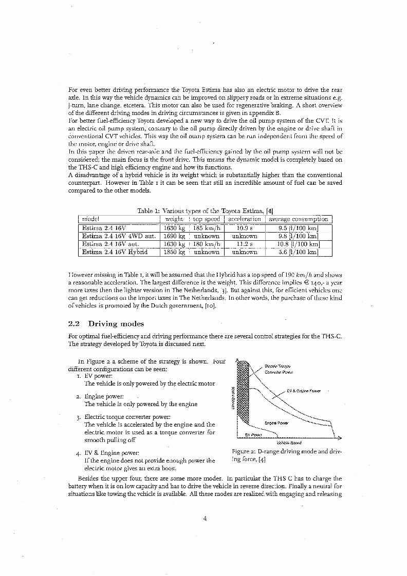
For even better driving performance the Toyota Estima has also an electric motor to drive the rearaxle. In this way the vehicle dynamics can be improved on slippery roads or in extreme situations e.g.j-tum, lane change, etcetera. This motor can also be used for regenerative braking. A short overviewof the different driving modes in driving circumstances is given in appendix B.For better fuel-efficiency Toyota developed a new way to drive the oil pump system of the CVT. It isan electric oil pump system, contrary to the oil pump directly driven by the engine or drive shaft inconventional CVT vehicles. This way the oil pump system can be run independent from the speed ofthe motor, engine or drive shaft.In this paper the driven rear-axle and the fuel-efficiency gained by the oil pump system will not beconsidered; the main focus is the front drive. This means the dynamic model is completely based onthe THS-C and high efficiency engine and how its functions.A disadvantage of a hybrid vehicle is its weight which is substantially higher than the conventionalcounterpart. However in Table I it can be seen that still an incredible amount of fuel can be savedcompared to the other models.
Table 1: Various types of the Toyota Estima. [41model I weight top speed acceleration I average consumption
Estima 2.4 16V 1630 kg 185 km/h 10.9 s 9.5 [1/100 km]Estima 2.4 16V 4WD aut. 1690 kg unknown unknown 9.8 [1/100 km]Estima 2.4 16V aut. 1630 kg 180 km/h 11.2 s 10.8 [1/100 km]Estima 2.4 16V Hybrid 1850 kg unknown unknown 5.6 [1/100 km]
However missing in Table I, it will be assumed thatthe Hybrid has a top speed of190 km/h and showsa reasonable acceleration. The largest difference is the weight. This difference implies € 140,- a yearmore taxe~ then the lighter version in The Netherlands, [3]. But against this, for efficient vehicles onecan get reductions on the import taxes in The Netherlands. In other words, the purchase ofthese kindofvehicles is promoted by the Dutch government, [10].
2.2 Driving modes
For optimal fuel-efficiencyand driving performance there are several control strategies for the THS-C.The strategy developed by Toyota is discussed next.
\!~~
Figure 2: D-range driving mode and driving force, [4]
3. Electric torque converter power:The vehicle is accelerated by the engine and theelectric motor is used as a torque converter forsmooth pulling off
4. EV & Engine power:Ifthe engine does not provide enough power theelectric motor gives an extra boost
Besides the upper four, there are some more modes. In particular the THS-C has to charge thebattery when it is on low capacity and has to drive the vehicle in reverse direction. Finally a neutral forsituations like towing the vehicle is available. All these modes are realized with engaging and releasing
In Figure 2 a scheme of the strategy is shown. Fourdifferent configurations can be seen:
1. EVpower:The vehicle is only powered by the electric motor
2. Engine power:The vehicle is only powered by the engine
4

oftwo clutches and a brake. In Table 2 these modes are shown, with an overview which clutch or braketo open and close.
Table 2: Operation chart of friction elements, [4]
I
Driving mode I CI I C2 I BI I~V ~ower I 0 I Ibngme power 0 0Electric torque converter power 0Reverse rangea 0 fo.P range charge 0N range
0: Engage, fo.: Slip.a CI: EV power, BI: Engine power (friction mode)
2.3 THS-C
The THS-C is based on the Super CVT (Kno) which originally is developed by Toyota in 2000, [4],[7]. The conventional torque converter is replaced by a torsional damper and motor generator, a crosssection can be seen in Figure 3.A schematic view of the THS-C is shown in Figure 4. From this latter view the dynamic model isderived, which is done in the next section.
Figure 3: Cross section oftransaxle, [4]
5
Figure 4: Schematic ofTHS-C, [4]

3 Modelling
In this section all the relevant equations will be derived. The explanations ofthe symbols can be foundin appendix A.
3.1 Equations of motion
To derive the equations of motion, first a model of the front drivetrain is composed. Figure 5 showsthe model of the front drive.
Figure 5: Model of the front drive
In Figure 5 the different parts of the front drivetrain can be seen. From the left to the right, theengine torque drives the inertia of the engine; a torsional damper is modelled with a linear springand damper and is directly connected to the planetary gear via the sun; the ring of the planetary gearcan be connected to the world through brake I (El), but is also connected to the primary pulley viaclutch 2 (G2); the electric motor having inertia Jm and torque T m is directly connected to the carrierbut can also be connected with the primary pulley by closing clutch I (Gl); the CVT is presented bytwo inertias and a time dependant ratio (Jprim , J sec and r(t)); the secondary pulley is connected tothe final reduction gear, which is further connected to the differential; the stiffuess of the axles tothe wheels is presented by two linear springs; the wheels are presented as inertias so there is no tyremodel included.The relevant torques and sign conventions are defined in Figure 6, with the positive direction to theright.
I I J1
"prim "'sec ~ ~
+ -{}- T~T ·T1
T T r.:i+\\ T . T .r:r-- kl kl'pnm. 'be~~'sec 'rd~'dL
V· Tkr~Tkr-[}-T. k, r
Jr
Figure 6: Definitions and sign conventions of the front drive
6

The relevant equations now can be derived. However, first a closer look at the planetary gearset istaken.
3.1.1 Planetary gear
In this paragraph the planetary gearset and its relevant equations are derived. The THS-C consists ofa double pinion planetary gear. Ifwe assume that all gear meshes in the planetary gear are mass-lesswe know that conservation ofpower must hold:
TTa Ts Tc
~ ~
"."·,,T
(1)
Figure 7: Planetary gear
In this equation we follow the sign conventions as in Figure 7. Furthermore,
P=T·w (2)
Because we assume there are no losses in the planetary gear we use equation (2) to solve equation (r),yielding:
And for the rotational speeds we know the follOwing must hold, [6]:
(3)
W s = (1 + z) . We - Z . W a'ra;z=-'r s
(4)
Because the planetary gear is a double pinion gear the characteristic geometric ratio i is defined to benegative. With equation (4), equation (3) can be rewritten into:
Te . We = Ts . ((1 + z) . We - Z . wa ) + Ta • W a
And:
We' (T~ - Ts . (1 + z)) = W a • (Ta - z· Ts )
(5)
(6)
This must hold for all w's so the torques are related to eaCh other according equation (7):
Te = (1 + z) . Ts
Ta = z· Ts . z == -~, T s
7
(7)

3.1.2 Dynamic equations
Now the equations of motion will be derived for the model of the front drive line. To start with theengine and the torsional damper:
Je . We = T e - T td
Ttd = ktd . (We - Ws ) + btd . (We - Ws )
Now the inertias of the planetary gear will be taken into account:
Js . Ws = T td - T s
Ja ,wa = -Ta - TEl - TC2
For the front motor/generator holds:
Jm . wm = T e + T m - TCI
The inertias of the CVT are modelled by:
Jprim • Wprim = T prim - TbeZt
Jsee . wsee = T see - Trd
The stiffness of the front axle can be modelled as:
T kz = kz . (wrdz - wz)
T kr = kr · (w rdr - Wr)
There is no model for the tyres, only the inertias of the wheels are modelled:
Jz"wz = Tkz - Tz
3.1.3 Kinematic equations
In section 3-1.1 we already mentioned equation 4, it is repeated here, [6]:
(8)
(9)
(10)
(11)
(12)
(13)
(14)
(15)
(16)
(17)
(18)
W s = (1 + z) . We - z· W a
For the differential holds:wz+wr
W see ' T"d = --2-
WprimW sec ==--
T"CVT
T"a;z=-
T"s(19)
(20)
(21)
3.1.4 Static equations
In section}I.I the static equations for the planetary gear are derived, the relevant equations are:
T,; = z·Ts
For the torques working on the primary pulley the following holds:
T prim = TCl + TC2
For the torques through the CVT holds:
T see = T beZt . T"CVT
And for the differential holds:
8
(22)
(23)
(24)
(25)
(26)

3.1.5 Stick / slip conditions
In the Toyota Estima two clutches and one brake are used to switch into the appropriate driving mode.To detect whether a clutch sticks or slips the 'Karnopp' approach is adopted, [8], [II]. Next for everyclutch the equations are derived.Clutch I: The torque which can be transmitted through a clutch depends on the clamping pressure.For C1 the following holds:
With:
(Tc + T m ) . Jprim + (Tbelt - TC2) . Jm
Jm + Jprim
n . p. A . R· /hCI . sign(wm - Wprim).
iflwm - wpriml < E:
and ITcll :; ITclstick Ielse
(27)
TCIstick = n· p. A· R . /hCIstick . sign(Tcl) (28)
This is the torque which can be maximally transmitted if the clutch sticks. /hClstick is always greaterthen /hCl, otherwise the clutch will never close smoothly. Equation {27} is clarified with Figure 8.
Figure 8: Stick/slip system for clutch 1
Clutch 2: The principal for C2 is the same as C1 only other torques apply for this subsystem, as canbe seen in Figure 9:
With:
(-Ta - TEl) . Jprim + (Tbelt - TCl) . Ja
Jprim + Ja
n· p' A· R· /hC2 . sign(wa - Wprim)
iflwa - wpriml < E:
and ITc21 :; ITC2stick Ielse
(29)
TC2 stick = n . p . A . R . /hC2 st ick . sign(Tc2)
J J.
Ti}-10~C
pnm
_TO --Tbe,t
Bl Tel
Figure 9: Stick/slip system for clutch 2
Brake I: For B1 holds:
(30)
( -Ta - TC2TEl = ~ )In· p . A . R . /hEI . sign(wa
with:
iflwal < E: A l1Bl! :; ITBlsticklelse
(31)
TEIstick = n . p . A . R . /hEIstick . sign(TEl )
This is clarified with Figure 10:
9
(32)

Figure 10: Stick/slip system for brake 1
The next step is to implement these equations into the Simulink modeL
3.2 Simulink
In Simulink the front drive is split up in different parts which interact with each other. The engineand torsional damper are two separate blocks. The planetary gear, the two clutches and the brake aregrouped in one block, but this block has three subsystems. In the first subsystem clutch I, in thesecond subsystem clutch 2, and in the third subsystem brake I are implemented. The CVT, final driveand axle are three separate blocks. The vehicle inertia and road resistance are modelled in one block.Finally, the drive modes and torque controller are also modelled in one block. In the next chapter theSimulink model and simulation results will be discussed in more detaiL
10

4 Simulation
To validate the model we only implement the model for the THS-C and a simple vehicle model. Priorto implementing the model in Advance we first simulate the model in basic Simulink. Advance isan advanced simulation tool with extended data-handling within the Simulink environment. Coupled power train and vehicle dynamics modelling can get quite complex, therefor the handling of theparameters and data is important.
4.1 Simulink
A model is implemented in Simulink to look how the THS-C operates. With the equations fromChapter 3 this model can be realized. First, we observe how parameters can be organized in 'Matlabstructures' .
4.1.1 Structures
For the handling ofthe vehicle parameters we choose to use structures, in order to divide the differentparts of the front drive into substructures. This enables easy adjustment of the parameters for eachpart. The input structure is called 'd'. This structure contains all the parameters which are used in themodel. The used structure for the drivetrain data can be found in appendix E.
4.1.2 Models
Now the different parts of the model will be discussed. The different blocks are:
1. Engine
2. Torsional damper
3. Planetary gear, the two clutches and the brake
4- CVT
5. Final drive
6. Axle
7. Drive modes & torque controller
These blocks can also be seen in appendix C. The engine, torsional damper, CVT, Final drive andaxle are relatively simple models, these are given in appendix D. In the next sections the model ofthe Planetary gear, the two clutches and the brake and the model of the driving modes and torquecontroller are further evaluated.
4.1.3 Planetary gear, the two clutches and the brake
For the clutches and the brake the same model is used. This to keep the model open and easy to adjustfor different configurations, i.e. locations of clutches and brakes. First the basic clutch model willbe discussed. To model a clutch a Matlab-function is written, this because slip and stick modes areeasier to describe in Matlab than in Simulink. If the clutch slips, a controllable torque is transmittedand the in- and output w's are not the same. If the clutch sticks the torque transmitted has a fixedrelation with the in- and output torques and the in- and output w's are the same, i.e. see equation(27). Because the clutch switches between these modes and we want this to be a smooth transition, asmooth slip control function must be designed. The m-file used is given in appendix F. The design ofthe slip control function lies outside the scope of this report. Some conceptual ideas for this functionare discussed in Serrarens, et al [8].
11

4.1.4 Driving modes & torque controller
The Toyota Estima is equipped with a new developed control strategy. This strategy was already shownin Figure 2. To imitate this strategy in the model, a subsystem is used which checks in what modethe drivetrain is operating and controls the clutches, see appendix F. In Figure II the CVT ratio and apercentage of the maximum throttle opening can be given as an input.
drive mod"S&b,l['lu~ l'~nt",lI"r
Figure 11: Simulink model of the driving modes & torque controller
In the block called "drive modes & torquecontroller" the m-file "drivemode" is used.This is given in appendix G. When the throt-tle opening is set to 50% and the CVT ra-tio is set to 2.396 we get Figure 12. In thebackground, Figure 2 from section 2.2 canbe seen. Here we can see the model startsin electric torque converter power mode andswitches into engine power mode. From Figure 2 the points are determined where theappropriate clutches and brake are (de-Jactivated,e.g. the vehicle top speed is set to 190 kmjh,so with this the maximum vehicle speed inEV-power can be evaluated, here this is around77 km/h. The maximum speed in electrictorque converter power mode is 21 km/h.
4.2 Results
200r----,------~----~---~
180
160
140
E 120
6(1)100
"1-"'0 80
60
Figure 12: Driving force versus the vehicle speed
For the simulations it is decided to investigate three different mode transitions. These are:
1. Clutch 2 closed from the beginning and clutch I closing during the simulation
2. Clutch ,2 closed from the beginning, during the simulation clutch 2. opens while dutch I doses,after some.time, clutch 2 closes again
3. Clutch 2 closed from the beginning, clutch I closes during the simulation. Then clutch 2 opensand after some time clutch 2 closes again
Some plots will be shown illustrating the above described mode transitions.
12

The first simulation is performed with constant throttle opening and CVT ratio. This simulationshows how the clutches close and how the speeds of the planetary gear gradually synchronize.
-~.!----~,".---~;,---"~,---,..,---I,
!~6 ry : Io. '0 ~ ~ .. .....
1~[ ['0
: :a• .. ~ ~ .. ..
'·:0 ,Eij• .. ~ ~ .. ..
'101
[J,-".-",
'{oj
(a) Planetary gear (b) Clutch I alld clutch 2
(cl Engine and motor (d) Fillal drive
Figure 13: Simulation with "CVT = 1.412 iUHI t.he throttle is 50% open
The start of the simulation is when the vehicle is standing still, then a step on the throttle is given andthe model starts in the electric torque converter mode. Both the engine and motor deliver power todrive the vehicle. Here can also be seen that the annulus and the primary CVT pulley have the samevelocities. Since the annulus and primary CVT pulley are direct connected with each other becauseclutch 2 is closed. After a while the vehicle is launched to about lOklll/h and the electric·motor is shutdown, so the vehicle is only powered by the engine. This is realized by engaging clutch I and keepingclutch 2 closed. which is called the engine power mode. [n engine power mode the electric motor doesnot give any power anymore, and the speeds of the engine and electric motor are the same. This wasalso expected because they are coupled with each other through the planetary gear, which members arenow linked to each other as clutch I and 2 are both closed and thus rotate at the same velocities. Thevehicles acceleration is not very high but this is caused by the constant CVT ratio. normally the CVTwill begin in 'low gear' and gradually shift up to 'overdrive', i.e. here from 2.:396 to 0.428. Controllingthe CVT, however, is left for future or may be similar to the control applied in other CVT vehicles
13

Here the results are shown with almost the same starting conditions as the first simulation, theCVT ratio is the only difference. Now the CVT is set to overdrive, which means the vehicle uses theCVT ratio which is normally used when the vehicle is already at a reasonable speed. This can becompared like the sixth gear in a manual transmission.
!•
(a) Planetary gear
-.,+-.-'._.
(b) Clutch 1 and clutch 2
(c) Engine a'ld motor (Ii) Final drive
Figme 14: Simulation with I"el'"l' = 0.428 and the thrott.le is 50% open
Here the vehicle is also standing still at the beginning of the simulation and a step on the throttleis given. The model starts in the electric torque converter mode, this mode is when a large drivingforce is needed and the vehicle speed is still low. Here again the annulus and primary CVT pulley aredirectly connected, so they have the same velocity. After a while the driving force is getting less andthe model switches to EV power mode. Here the velocities of the electric motor and the primary cvrpulley are the same, this because clutch I is closed. In this mode the engine delivers no power. Thespeed is still increasing because the throttle is still open, after some time clutch 2 is engaged and themodel is in engine power mode, here the electric motor delivers no power. Now the planetary gearhas a ratio of I, because both clutch I and 2 are closed. The annulus, carrier and sun have the samevelocity, In this simulation the acceleration is worse then before, this is like expected because the CVIratio is set to 'overdrive',
14

The next simulation is initially the same as the simulation shown before. but the throttle openingis varied. The cvr ratio is set to 1.0088, which would provide the vehicle a higher acceleration fromstandstill. The simulation also shows how the model reacts on a period ofless throttle during driving.
i•
• • •
/.'"S4iii4•• ,"" /
~'-----.•••• '211 ••••
'" · '"'211 •••aI
Ca) Planetary gear (b) Clutch I and clutch 2
,
~F }J!':~ ~~°0 20 • • • ,. ,oo ,oo ,oo • • • • • ,. ,oo ,oo ,oo_.
fJ•-
i~Lioo> ..
'.-2lIOO :to • • • ,. ,oo 'oo ,oo • • • • ,. ,oo ,oo ,oo
'" I{')
(c) Engine and motor (d) Final drive
'"...".
lU'
I""" .
. '" ........ ,...."Ce) Throule openins
Figure 15: Simulation with rC\'T = 1.0088 and variable throttle opening
Again the vehicle starts with clutch 2 closed, electric torque converter power mode. After a whileclutch I closes, with clutch 2 still closed, engine power mode. Then there is no throttle given and thevehicle slows down and the driving force decreases quickly, clutch 2 opens and the vehicle gets in EVpower mode. When throttle opening is resumed the vehicle starts to accelerate again and after a shorttime clutch 2 closes again to get in engine power mode. Now, the velocities ofthe engine and electricmotor become quite high so normally the CVT would be shifted up to restrict the engine revolutionsto its operational maximum. In this simulation it can be clearly seen that the vehicle is slowing downwhen the throttle is closed, this is due to air- and rolling-resistance.
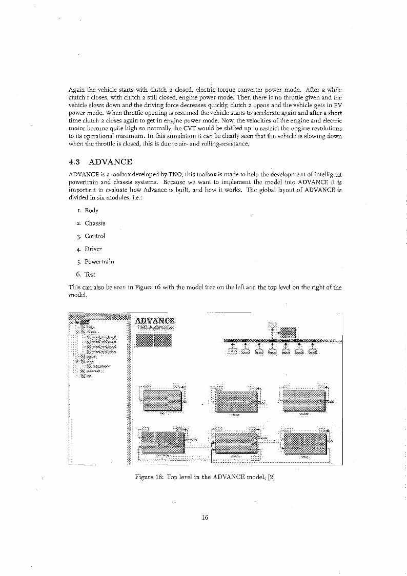
4.3 ADVANCE
ADVANCE is a toolbox developed by TNO, this toolbox is made to help the development of intelligentpowertrain and chassis systems. Because we want to implement the model into ADVANCE it isimportant to evaluate how Advance is built, and how it works. The global layout of ADVANCE isdivided in six modules, i.e.:
I. Body
2. Chassis
3· Control
4· Driver
5· Powertrain
6. Test
This can also be seen in Figure I6 with the model tree on the left and the top level on the right ofthemodel.
Figure 16: Top level in the ADVANCE model; [2]
16

For each module TNO has made some models. The powertrain and control module have to be refurnished with the THS-C modeL The standard parts can be used from ADVANCE, like the CVT,differential, axle and engine model. Some standard parts TNO has developed, like the tyre model andthe driver, chassis, test and body module can also be used. But the parameters have to be adjusted tomake these models resemble the Toyota Estima Hybrid. However the Toyota Estima Hybrid is onlyavailable on the Japanese market its hard to find all the parameters. The parameters ofthe 'normal' Estima or Previa, which is available on the European market, can be used for the major part. In appendixH an overview of all the parameters found can be seen.
17

5 Conclusions and recommendations
The main goal of this traineeship is to model the drive train of the Toyota Estima Hybrid. This is firstdone in Matlab Simulink, and after this it should be implemented into ADVANCE. But because of thetime restrictions it was not possible to make the model fully operational in ADVANCE, and the goalwas to model the front drive of the Toyota Estima Hybrid in Matlab Simulink. In chapter 4 the resultsof some simulations can be seen, from which we can conclude that the model displays a comprehensive representation of the real drive train. The clutches switch on at the desired time and the torquesare representative. But some aspects are not modelled yet. For instance, the control strategy of theCVT is not modelled so there is chosen to set the CVT on a constant ratio.
Some recommendations are, to implement the rear motor generator together with regenerative braking, this will make the model having a closer resemblance to the real vehicle.Another recommendation is to implement the model in ADVANCE and to use the already developedvehicle and chassis modules ofADVANCE. This because TNO build these module~ and they are welltested with experiments. The hardest part may be to determine the right parameters which are neededin the ADVANCE modules. It is hard to find all the parameters of the Toyota Estima Hybrid, thisbecause this vehicle is only sold in Japan and rtlOst ofthe information is in Japanese.Also in Matlab Simulink there is new environment called 'SimDriveline', this has blocks to model adrive line, like inertias and torsional springs. With this toolbox it is simpler to make a model of apower train. It would also be nice to compare the simulations ofthe Toyota Estima Hybrid with simulations of the conventional Toyota Estima, so the difference between the hybrid configuration and the'normal' configuration can be seen. .
On the 74th Geneva international Motor Show [5] Lexus, which is a part of Toyota, presented a newmodel called the RX4ooh. This model makes use of the configuration as the Toyota Prius Hybrid.This is another hybrid configuration and is also designed to gain more fuel efficiency. The differencewith the Estima is that this car will be sold in Europe, so it would be easier to gain more information about this car. This would make it easier to create a dose matching total model. And if thereare reasonable results from the complete vehicle model, some tests could be conducted to verify thesimulations.
18

A Symbols
The symbols used stand for:
symbol description unit
[W]powerp'1' torque [Nm]w rotational speed [rad/s]z planetary gear ratio [-]r radius or ratio [m]J inertia [kgm2 ]
k spring stiffness [N/m]b damping stiffness [Ns/mJ or [NsmJn number of friction surfaces [-]p control pressure [N/m2
]
A pressure surface [m2]
R effective ratio [m]
f.lo tangential friction coefficient [-]
Table 3: Symbols
And the subscripts stand for:
description
s sunc carriera annuluse enginetd torsional damperm motor/generatorC1 clutch 1C2 clutch 2B1 brake 1
stick holds if the clutch/brake is closedprim primary pulleybelt CVT beltsec secondary pulleyd differential
CVT CVTkl stiffness of the left rearaxlekr stiffness of the right rearaxlel left
I symbol I
r right
Table 4: Explanation of subscripts
19

B Driving modes
(a) EV power (b) Engine power and recharging battery
Figure 17: EV power & engine power and recharging battery mode, [9]
Figure q(a) EV power, the vehicle is driven by the front and rear motors, 4WD. Figure q(b) enginepower and recharging battery mode, the vehicle is driven by the engine and the engine drives the frontmotor simultaneously which recharges the battery.
(a) EV & engine power (b) 4WD mode
.Figure 18: EV power & engine power and 4WD mode, [9J
Figure I8(a) EV & engine power, the vehicle is driven by the engine and the front and rear motor,4WD. Figure 18(b) 4WD mode, the vehicle is driven by the engine and the engine drives the front
20

motor simultaneously which recharges the battery. And the rear motor is used to drive the rear wheels,4WD.
(a) Regenerative braking (b) Electric torque converter power
Figure 19: Regenerative braking & electric torque converter power, [9]
Figure 19(a) regenerative braking, the vehicle drives both the front and rear motor to recharge thebattery. Figure 19(b) electric torque converter power, the vehicle is driven by the front and rear motorat low speeds when extra power is needed, 4WD.
21

C Model
drin m<>d",,&.wrqu", "'mh"n,,,
IPC11)---_t_-i>j
IPC2J)---_t_->j
~~J>----_t_->j
-,""1------,
.-1-1----,
Figure 20: Model in Simulink
22

D Sub-models
Tengine:
Tenginl!
(a) Engine model
(2J-----.Jx
(b) Torsional damper model
wprilTi
drive1ralna;~eler;;tijJn
dws"l'
(c) CVT model
3
Tfd
(d) Final drive model (e) Axle model
Figure 21: Sub-models of the total model seen in appendix C
23

E Drivetrain data.m
%Drivetrain data:%This file contains all the parameters for the drive train%This file has to be run before running the model
d = [ ];
%Engine (2AZ-FXE):d.engine.Je = 0.13; %[kg(m-2)]%Engine torque characteristics:d.engine.w [ 0 1000 1100 1700 1900 2300 2800 3600 3700 4000 4800 5100
5500 5700 ]; % [rpm]d.engine.T [ 0 0 137 160 164 168 179 188 190 190 180 175
167 160]; % [Nm]
%Motor torque characteristics:d.motor.w [0 1130 1240 1500 2000 2500 3000 3500 4000 4500
5000 5600]; % [rpm]d.motor.T 110 110 100.11 82.76 62.07 49.65 41.38 35.46 31.03 27.58
24.82 22.16 ]; % [Nm]
% [N/m]% [Ns/m]% [kg(m-2)]% [kg(m-2)]
(K110) :
6e3;9300;0.1;0.1;
%SUPERCVTd.CVT.ktdd.CVT.btdd.CVT.Jprim =d.CVT.Jsec
1 .,1.20.1
2 .,0.50.127
% Clutchl:d.clutch1.nd.clutchl.Ad.clutch1.Rd.clutch1.mjud.clutchl.mjustickd.clutchl.epsilon
d.clutchl.cst
d.clutchl.cstick
% [-], number of friction surfaces% [m-2], pressure surface% em], effective ratio% [-], tangential friction coefficient% [-]% [-], small coefficient ...
... to detect wether the clutch sticks or slipsd.clutchl.n*d.clutchl.A*d.clutchl.R*... d:clutchl.mju; % [-]d.clutchl.n*d.clutchl.A*d.clutchl.R*... d.clutchl.mjustick; % [-]
%Clutch2:d.clutch2.nd.clutch2.Ad.clutch2.Rd.clutch2.mjud.clutch2.mjustickd. clutch2. epsilond. clutch2. cst
d.clutch2.cstick
2 ; % [-]0.5 % [m-2]0.127 % em]1 ; % [-]1.2; % [-]0.1; % [-]d.clutch2.n*d.clutch2.A*d.clutch2.R*... d.clutch2.mju; % [-]d.clutch2.n*d.clutch2.A*d.clutch2.R*... d.clutch2.mjustick; % [-]
24

% Brakel:d. brakel.nd. brake1. Ad.brake1.Rd.brake1.mjud.brakel.mjustickd.brakel.epsilond.brakel.cst
d.brakel.cstick
2; % [-]0.5; % [m-2]0.127; % [m]1; % [-]1.2; % [-]0.1; % [-]d.brakel.n*d.brakel.A*d.brakel.R*
... d. brake1.mju; % [-] .d.brakel.n*d.brakel.A*d.brakel.R*
... d.brakel.mjustick; % [-]
% Planetary gear:d.planetarygear.Jsd.planetarygear.Jad.planetarygear.Jmd.planetarygear.z
% Final drive:d.finaldrive.gearratiod.finaldrive.Jd.finaldrive.broadd.finaldrive.kaxle
0.01;0.01;0.01;-1.754
5.182;0.7;le3;le3;
% [kg(m-2)]% [kg(m-2)]% [kg(m-2)]% [-]
% [-]% [kg(m-2)]% [Ns/m]% [N/m]
% Tyre diameter 205/65 R15:d.tyre.diameterd.tyre.radiusd.tyre.contourlengthd.tyre.fr
% Vehicle parameters:d.vehicle.massd.vehicle.Jeqd.vehicle.Cdd.vehicle.wheelbased.vehicle.frtrckwdd.vehicle.rrtrckwdd.vehicle.hd.vehicle.A
d.drivemode.vETCd.drivemode.vEV
%Air coefficients:
2*0.65*0.205+0.0254*15; % [m]d. tyre. diameter/2; % [m]pi*d.tyre.diameter; % [m]d.vehicle.mass*d.roadload.g*d.tyre.froll;... rolling resistance
1850; % [kg]d.vehicle.mass*(d.tyre.diameter/2)-2;0.3; % [-]2.9; % [m]1.545; % [m]1.530; % [m]1. 780; % [m]d.vehicle.h*d.vehicle.frtrckwd; % [m-2]
21/3.6; %[m/s]77/3.6; %[m/s]
% [N] ...
d.air.rhod.air.resist
1.293; % [kg/m-3]0.5*d.air.rho*0.3*d.vehicle.A; % [N], air resistance
25

F Switchfunction.m
function [output] = switchfunctotappart(u,Jl,J2,cst,cstick,eps);
%This function detects wether the clutch/brake sticks or slips.%First it detects in what state the clutch/brake is and out of the input it%calculates/decides if the clutch/brake switches or stays in the same state.
%FunctionpressurewinwoutTinToutTCstick
inputs:u(l); %u(2); %u(3); %u(4); %u(5); %u(6); %u(7); %
[N/m-2][rad/s][rad/s][Nm], input torque[Nm], output torque[Nm], transferred torque[-], wether the clutch/brake sticks or slips; 1/0
%Speed difference between in- and output:delta_w win-wout; % [rad/s]
%If clutches are slipping the following interface torques apply:%TC_slip cst*pressure*sign(delta_w); % [Nm]
torques apply:% [Nm]% [Nm]
% If clutches%TCl stick%TC2 stick%TBl stick
are sticking the following interface(J2*(Tc+Tm)+Jl*(Tbelt-TC2))/(Jl+J2);(J2*(Ta-TB1)+Ja*(Tbelt-TC1))/(J2+Ja);Ta; % [Nm]
Tclutchmax%Tslip% if J2 > 0
cstick*pressure*sign(TC);cst*pressure*sign(delta_w);
% [Nm]% [Nm]
%First detectif stick == 1,
Tclutch3else
Tclutch3end
if the clutch/brake is already closed:%if this is true, the transferred torque is calculated(J2*(Tin)+Jl*(-Tout))/(Jl+J2); % [Nm], transferred torque%if the clutch/brake slips the transferred torque is differentcst*pressure*sign(delta_w); % [Nm], transferred torque
%Now its examined if the clutch/brake switches or not:if abs(delta_w) <= eps & abs(TC) < abs(Tclutchmax)
TC Tclutch3; % [Nm]dwl = l/Jl*(Tin-TC); % [rad/s-2], input accelerationdw2 = dwl; % [rad/s-2], output accelerationstick = 1; % [-J, the clutch/brake is closed
else
end
TCdwldw2stick
Tclutch3;l/Jl*(Tin-TC);1/J2*(Tout+TC)*(J2>0);= 0;
% ENm]% [rad/s-2]% [rad/s-2]% [-J, the clutch/brake is opened
%Function outputs:output = [TC,stick,dwl,dw2J;
26

G Drivemode.m
function [output] = drivemode(u,vETC,vEV,tyrediameter,gearratio)
%This function detects in what kind of driving mode the vehicle is and which%clutch/brake should be closed/opened.
%Function inputs:speed u(l) ; % [m/s] , vehicle speedTmotor u(2); % [Nm], torque delivered by the electric motorTengine u(3); % [Nm], torque delivered by the IC engineR u(4); %total gear ratiothrottle u(5) ; % [-J, throttle opening on a range of 0 to 1
TmaxTused
ifC1C2B1EVE
elseifC1C2B1EV
Eelseif
C1C2B1EVE
elseifC1C2B1EVE
elseifC1C2B1EVE
end
Tmotor + Tengine; %maximum possible torquethrottle*Tmax; %used torque
speed <= vEV & Tused <= Tmotor; %EV power1 ;0;0;Tused;0;
speed <= vETC & Tused > Tmotor; %Electric torque converter power0;1;0;(Tused - Tmotor) / (Tmax - Tmotor)* ...
(Tmotor - Tmotor / (gearratio / (1 + gearratio») + ...... Tmotor / (gearratio / (1 + gearratio»;
= -1 / (1 + gearratio)*EV;speed> vETC & speed <= vEV & Tused > Tmotor & Tused <= Tengine; ...% ••• Engine power
1 ;1 ;0;0;Tused;
speed> vETC & Tused >= Tengine; %EV & engine power1 ;1;0;(Tused-Tengine);
= Tengine;speed> vEV & Tused < Tengine; %Engine power
1;1 ;0;0;Tused;
%Function outputs:output = [ C1,C2,B1,EV,E ];
27

H Toyota Estima Hybrid specifications
Car model number ZA-AHRI0WNumber of seats 7-8Engine code 2AZ-FXE
I Engine type Otto, front transversal INumber of cylinders 4, in-lineEngine capacity 2362cm3
Fuel Hybrid, injected by cylinderSupercharging NoneBore 88.5mmStroke 96mmCompression ratio 12.5Maximum power 96kW(JIS)5600rpmMaximum torque 190Nm(rpm)4000rpmDrive front-wheel driveGearbox 4 autoSteering type Hydraulic powerWheels 6.55JJ x 15Front tyres 205/65R15Rear tyres 205/65R15Front suspension MacPherson strut, coil spring, stabilizer barRear suspension Coil spring, torsion beam, stabilizer barWheelbase 2900mmLength 4770mmWidth 1790mmHeight 1780mmTrack (front) 1545mmTrack (rear) 1530mmCurb weight 1850 - 860kgTrunk 495l- 2370lFuel tank 75lAverage consumption 5.6l/100km(work)Front motor/generator lEMvoltage 216VMaximum power 13kW(1130 - 3000rpm)Maximum torque 1l0Nm(O - 1130rpm)Rear motor/generator IFMvoltage 216VMaximum power 18kW(1910 - 2500rpm)Maximum torque 108Nm(O - 400rpm)
Table 5: Specifications of the Toyota Estima MPV 2.4 16v Hybrid
28

References
[I] Koraku (4-8) and Bunkyo-ku (I-chome), Toyota Hybrid System, THS II, May 2003, Compiled byToyota Motor Corporation, Public Affairs Division.
[2] TNO Automotive ADVANCE brochure, http://www.automotive.tno.nl/vd/docsjbrochurcadvance.pdf
[3] Tax collectors office, http://www.belastingdienst.nl. Belastlngdienst, in Dutch only.
[4] Hiroatsu Endo, Masatoshi Ito, and Tatsuya Ozeki, Development of Toyota's transaxle for mini-vanhybrid vehicles, JSAE 24 (2003), I09-II6.
[5] Geneva international Motor Show, http://www.salon-auto.ch/enj.
[6] G. Lechner and H. Naunheimer, Automotive transmissions, Springer-Verlag, 1994.
[7] Masabumi Nishigaya, Tadashi Tamura, Hideki Yasue, Shinji Kasuga, and Masami Sugaya, Development of Toyota's New "Super CVT", SAE (2001).
[8] A.F.A. Serrarens, M.H.M. Dassen, and M. Steinbuch, Simulation and Control of an AutomotiveDry Clutch, ACC (2004)'
[9] Toyota, http://www.toyota.cojp/showroom/aILtoyota_lineupjestimahybridjmechanismjindeX1.html.
[ro] Platform Clean Vehicles, http://www.platformschonevoertuigen.nl/.PlatformSchoneVoertuigen.inDutch only.
[II] B.G. Vroemen, Component Control for the Zero Inertia powertrain, Eindhoven University ofTechnology, 2001.
29