Signal Quality Analysis in Pulse Oximetry: Modelling and ...
ANDRES/TUV/R/D1.4b/1.0 Confidential Modelling forsignal processing architectures, final library elements
IST‐5‐ 033511 ANDRES
ANalysis and Design of run‐time REconfigurable, heterogeneous Systems
Project Duration 2006‐06‐01 – 2009‐05‐31 Type STREP
WP no. Deliverable no. Lead participant
WP1 D1.4b TUV
Modelling of signal processing architectures, final library elements
Prepared by Jiong Ou – TUV, Jan Haase – TUV
Issued by TUV
Document Number/Rev. ANDRES/TUV/P/D1.4b/1.0
Classification ANDRES Confidential
Submission Date 2008‐11‐28
Due Date 2008‐11‐30 Project co‐funded by the European Commission within the Sixth Framework Programme (2002‐2006)
© Copyright 2006 .Diseno de Sistemas en Silicio S.A., Kungliga Tekniska Högskolan, OFFIS e.V., Universidad de Cantabria, Thales Communications S.A, Vienna University of Technology This document and the information contained herein may not copied, used or disclosed in whole or in part outside of the consortium except with prior written permission of the partners listed above.

ANDRES/TUV/R/D1.4b/1.0 Confidential Modelling for signal processing architectures, final library elements
Page 2
History of Changes
ED. REV. DATE PAGES REASON FOR CHANGES
JO 0.1 2008‐11‐21 39 Initial version
JH 0.2 2008‐11‐21 41 Cleanup, styling, typo corrections
JH 0.3 2008‐11‐24 50 Example included
JO 0.4 2008‐11‐25 56 +figures, appendix
JO 0.5 2008‐11‐28 55 End version

ANDRES/TUV/R/D1.4b/1.0 Confidential Modelling for signal processing architectures, final library elements
Page 3
Contents
1 Overview ............................................................................................................................ 5 2 Signal Sources..................................................................................................................... 6 2.1 Uniformly distributed random Numbers ................................................................... 6 2.2 Gaussian distributed random Numbers ..................................................................... 7 2.3 Uniformly distributed random Bits ............................................................................ 7 2.4 Sine ............................................................................................................................. 7 2.5 Square Wave .............................................................................................................. 9 2.6 Triangle Wave........................................................................................................... 10 2.7 Saw tooth Wave ....................................................................................................... 10
3 Basic blocks for Signal processing .................................................................................... 11 3.1 Mathematical functions ........................................................................................... 11 3.1.1 Adder ................................................................................................................ 11 3.1.2 Subtractor......................................................................................................... 11 3.1.3 Multiplier.......................................................................................................... 12 3.1.4 Division ............................................................................................................. 12 3.1.5 Integrator ......................................................................................................... 13 3.1.6 Logarithm ......................................................................................................... 13 3.1.7 Tan function ..................................................................................................... 13
3.2 Nonlinearities ........................................................................................................... 14 3.2.1 Saturation......................................................................................................... 14 3.2.2 Deadzone.......................................................................................................... 14 3.2.3 Coulomb function............................................................................................. 15
3.3 Basic RF building blocks............................................................................................ 15 3.3.1 Gain .................................................................................................................. 15 3.3.2 Offset ................................................................................................................ 16 3.3.3 Quadrature Mixer............................................................................................. 16 3.3.4 A/D and D/A converter..................................................................................... 18 3.3.5 Low‐noise amplifier (LNA) ................................................................................ 19 3.3.6 Mixer................................................................................................................ 20 3.3.7 Butterworth filter ............................................................................................ 20 3.3.8 Chebyshev filter................................................................................................ 21 3.3.9 45° Shifter......................................................................................................... 22 3.3.10 Gaussian Wave‐shaping filter........................................................................... 22 3.3.11 Digital VCO........................................................................................................ 23 3.3.12 Analogue VCO................................................................................................... 24 3.3.13 Lowpass‐filter ................................................................................................... 24 3.3.14 Phase Detector (Comparator) .......................................................................... 25 3.3.15 Phase‐locked loop ............................................................................................ 25 3.3.16 Channel............................................................................................................. 26
3.4 Modulation/Demodulation ...................................................................................... 27 3.4.1 Amplitude Modulation ..................................................................................... 27 3.4.2 Binary Amplitude Shift Keying (BASK) Modulator............................................ 27 3.4.3 BASK Demodulator ........................................................................................... 28 3.4.4 Binary Phase Shift Keying (BPSK) Modulator ................................................... 29 3.4.5 BPSK Demodulator ........................................................................................... 29

ANDRES/TUV/R/D1.4b/1.0 Confidential Modelling for signal processing architectures, final library elements
Page 4
3.4.6 DBPSK Modulator ............................................................................................. 30 3.4.7 DBPSK Demodulator......................................................................................... 31 3.4.8 QPSK Modulator ............................................................................................... 31 3.4.9 QPSK Demodulator........................................................................................... 32 3.4.10 Offset QPSK (OQPSK) Modulator ..................................................................... 33 3.4.11 OQPSK Demodulator ........................................................................................ 33 3.4.12 DQPSK Modulator ............................................................................................ 34 3.4.13 DQPSK Demodulator ........................................................................................ 34 3.4.14 M‐FSK Modulator ............................................................................................. 35 3.4.15 M‐PSK Modulator ............................................................................................. 36 3.4.16 QAM Mapper.................................................................................................... 36 3.4.17 QAM Demapper ............................................................................................... 37 3.4.18 FFT/IFFT ............................................................................................................ 38 3.4.19 OFDM modulator (OFDM transmitter) ............................................................ 38 3.4.20 OFDM demodulator (OFDM Receiver)............................................................. 39
3.5 Miscellaneous........................................................................................................... 40 3.5.1 Up‐Sample ........................................................................................................ 40 3.5.2 Down‐Sample ................................................................................................... 40 3.5.3 Parallel to Serial................................................................................................ 41 3.5.4 Serial to Parallel................................................................................................ 41 3.5.5 Signal splitter.................................................................................................... 42
4 Signal analysis units.......................................................................................................... 42 4.1 Eye Diagram.............................................................................................................. 42 4.2 Scatter Plot ............................................................................................................... 43 4.3 Network analyzer ..................................................................................................... 43
5 Example: OFDM Transmitter system ............................................................................... 44 6 Conclusion and future work ............................................................................................. 50 7 References........................................................................................................................ 51 8 Appendix........................................................................................................................... 52

ANDRES/TUV/R/D1.4b/1.0 Confidential Modelling for signal processing architectures, final library elements
Page 5
1 Overview Simulation of signal processing systems and communication systems usually tends to be slow in standard simulation environments as the high frequencies lead to very small time steps and therefore many calculations. SystemC AMS offers modelling in Timed Data Flow (TDF) which allows faster simulations as the scheduling is done in advance. However, the modelling is a slow process as the system designer has to create most parts of his system “by hand”. In this part of ANDRES, a modelling approach is developed that provides building blocks to ease the design process, relieving the designer from their detailed implementation and giving him more time for the harder problems in his design. The implemented building blocks focus on the field of communication and radio frequency systems, in particular on signal sources, modulation/demodulation blocks, filters, measurement and observation parts. They can be subdivided into three categories of blocks:
• Signal sources • Basic blocks for signal processing • Signal analysis units
Currently the library components are augmented with means for specification of re‐configurability, and means to model physical implementations of re‐configurability where possible. In the next Sections all of the implemented modules will be described uniformly with:
• Functional description • Module definition • Module interface • Adjustable parameters • Module implementation if necessary • Simulation example with results by several modules
After the description of all of the implemented modules a relative complex communication system, an exemplary OFDM transmitter system, is built up and simulated using modules from the building blocks library to present the usage of the library and how it can improve the efficiency of designing and modelling of communication systems. Conclusions and future works about the building block library are given in the last chapter of the deliverable. This deliverable is based on D1.4a, “Modelling of signal processing architectures, initial library elements” [6].
ANDRES/TUV/R/D1.4b/1.0 Confidential Modelling for signal processing architectures, final library elements
Page 6
2 Signal Sources This Section describes several modules of signal sources.
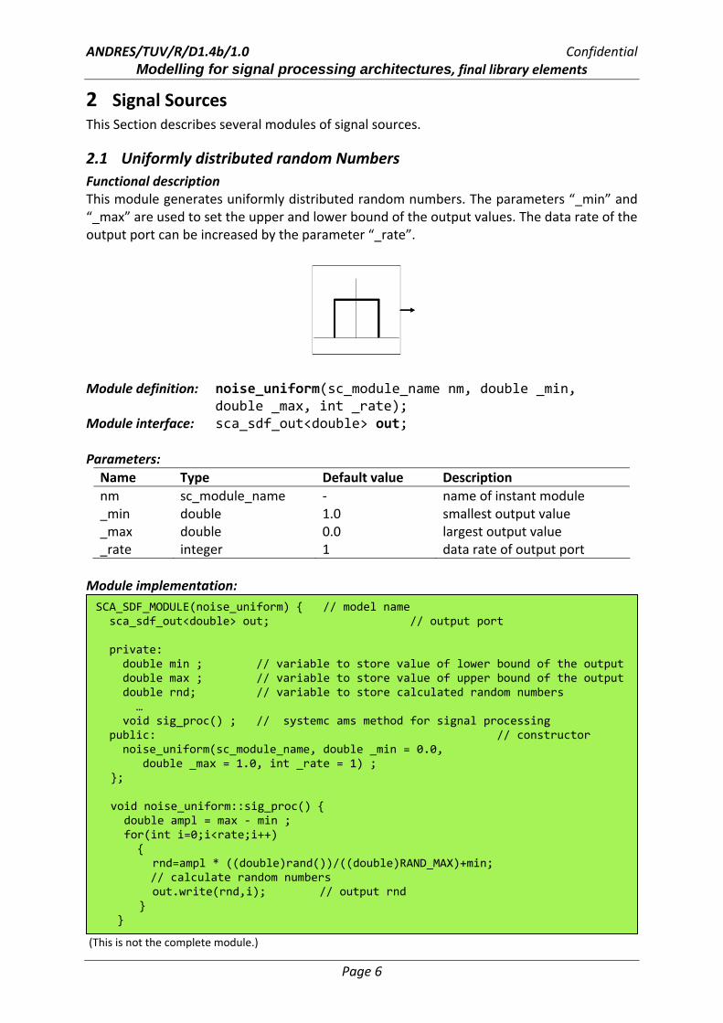
2.1 Uniformly distributed random Numbers Functional description This module generates uniformly distributed random numbers. The parameters “_min” and “_max” are used to set the upper and lower bound of the output values. The data rate of the output port can be increased by the parameter “_rate”.
Module definition: noise_uniform(sc_module_name nm, double _min, double _max, int _rate);
Module interface: sca_sdf_out<double> out; Parameters: Name Type Default value Description nm sc_module_name ‐ name of instant module _min double 1.0 smallest output value _max double 0.0 largest output value _rate integer 1 data rate of output port
Module implementation:
(This is not the complete module.)
SCA_SDF_MODULE(noise_uniform) { // model name sca_sdf_out<double> out; // output port private: double min ; // variable to store value of lower bound of the output double max ; // variable to store value of upper bound of the output double rnd; // variable to store calculated random numbers … void sig_proc() ; // systemc ams method for signal processing public: // constructor noise_uniform(sc_module_name, double _min = 0.0, double _max = 1.0, int _rate = 1) ;
};
void noise_uniform::sig_proc() { double ampl = max ‐ min ; for(int i=0;i<rate;i++) { rnd=ampl * ((double)rand())/((double)RAND_MAX)+min; // calculate random numbers out.write(rnd,i); // output rnd } }
ANDRES/TUV/R/D1.4b/1.0 Confidential Modelling for signal processing architectures, final library elements
Page 7
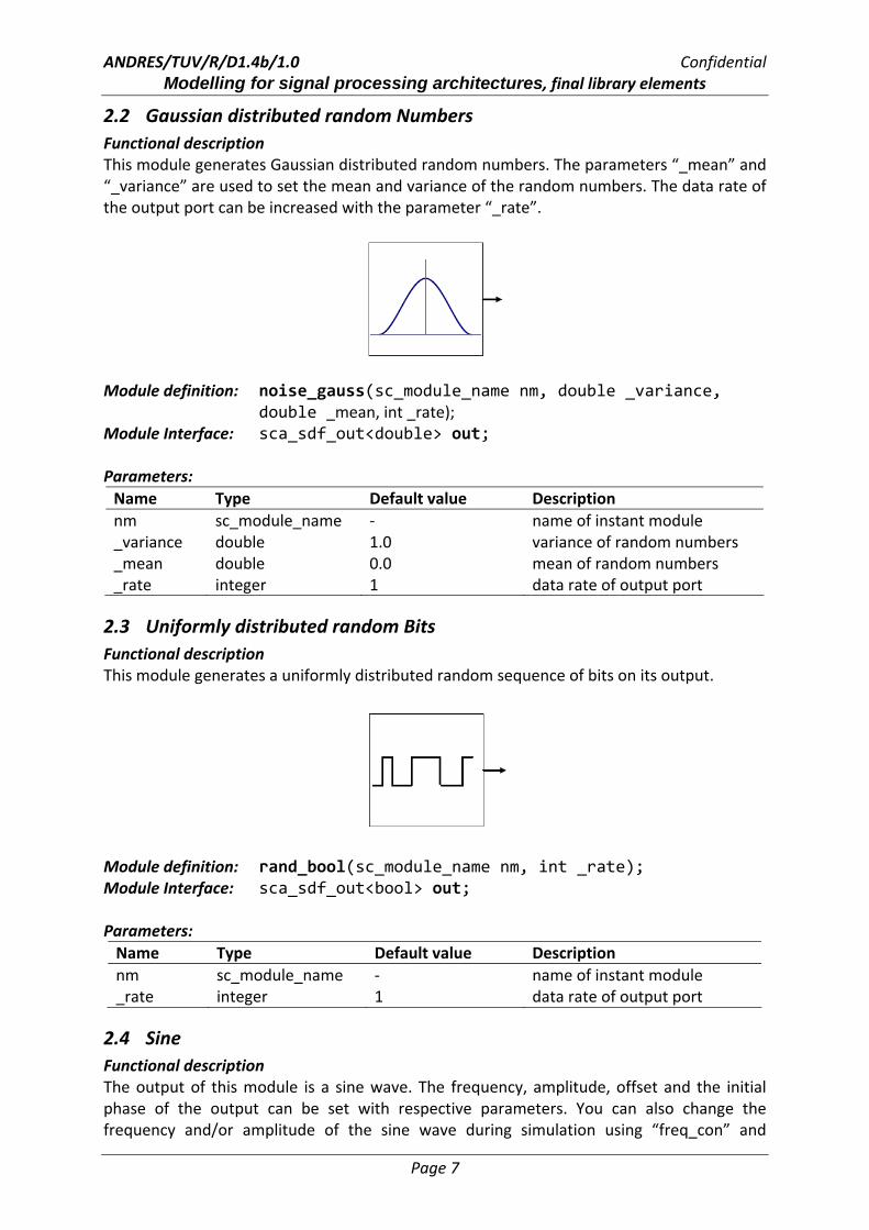
2.2 Gaussian distributed random Numbers Functional description This module generates Gaussian distributed random numbers. The parameters “_mean” and “_variance” are used to set the mean and variance of the random numbers. The data rate of the output port can be increased with the parameter “_rate”.
Module definition: noise_gauss(sc_module_name nm, double _variance, double _mean, int _rate); Module Interface: sca_sdf_out<double> out; Parameters: Name Type Default value Description nm sc_module_name ‐ name of instant module _variance double 1.0 variance of random numbers _mean double 0.0 mean of random numbers _rate integer 1 data rate of output port
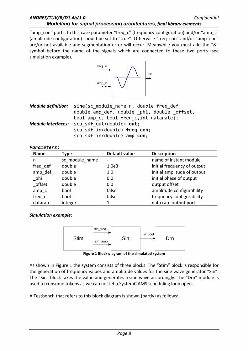
2.3 Uniformly distributed random Bits Functional description This module generates a uniformly distributed random sequence of bits on its output.
Module definition: rand_bool(sc_module_name nm, int _rate); Module Interface: sca_sdf_out<bool> out; Parameters: Name Type Default value Description nm sc_module_name ‐ name of instant module _rate integer 1 data rate of output port
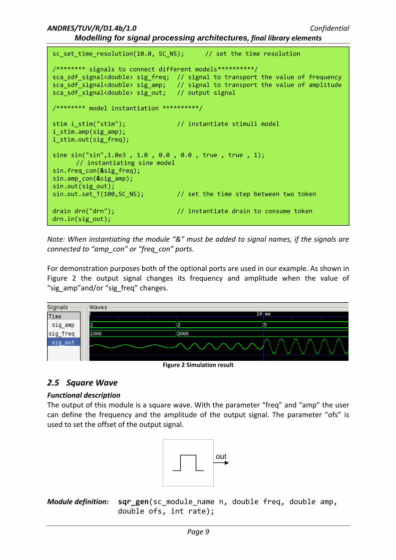
2.4 Sine Functional description The output of this module is a sine wave. The frequency, amplitude, offset and the initial phase of the output can be set with respective parameters. You can also change the frequency and/or amplitude of the sine wave during simulation using “freq_con” and
ANDRES/TUV/R/D1.4b/1.0 Confidential Modelling for signal processing architectures, final library elements
Page 8
“amp_con” ports. In this case parameter “freq_c” (frequency configuration) and/or “amp_c” (amplitude configuration) should be set to “true”. Otherwise “freq_con” and/or “amp_con” are/or not available and segmentation error will occur. Meanwhile you must add the “&” symbol before the name of the signals which are connected to these two ports (see simulation example).
Module definition: sine(sc_module_name n, double freq_def,
double amp_def, double _phi, double _offset, bool amp_c, bool freq_c,int datarate);
Module Interfaces: sca_sdf_out<double> out; sca_sdf_in<double> freq_con;
sca_sdf_in<double> amp_con; Parameters: Name Type Default value Description n sc_module_name ‐ name of instant module freq_def double 1.0e3 initial frequency of output amp_def double 1.0 initial amplitude of output _phi double 0.0 initial phase of output _offset double 0.0 output offset amp_c bool false amplitude configurability freq_c bool false frequency configurability datarate integer 1 data rate output port
Simulation example:
Stim Sin Drn
sin_freq
sin_amp
sin_out
Figure 1 Block diagram of the simulated system
As shown in Figure 1 the system consists of three blocks. The “Stim” block is responsible for the generation of frequency values and amplitude values for the sine wave generator “Sin”. The “Sin” block takes the value and generates a sine wave accordingly. The “Drn” module is used to consume tokens as we can not let a SystemC AMS scheduling loop open. A Testbench that refers to this block diagram is shown (partly) as follows:
ANDRES/TUV/R/D1.4b/1.0 Confidential Modelling for signal processing architectures, final library elements
Page 9
Note: When instantiating the module “&” must be added to signal names, if the signals are connected to “amp_con” or “freq_con” ports. For demonstration purposes both of the optional ports are used in our example. As shown in Figure 2 the output signal changes its frequency and amplitude when the value of “sig_amp”and/or “sig_freq” changes.
Figure 2 Simulation result
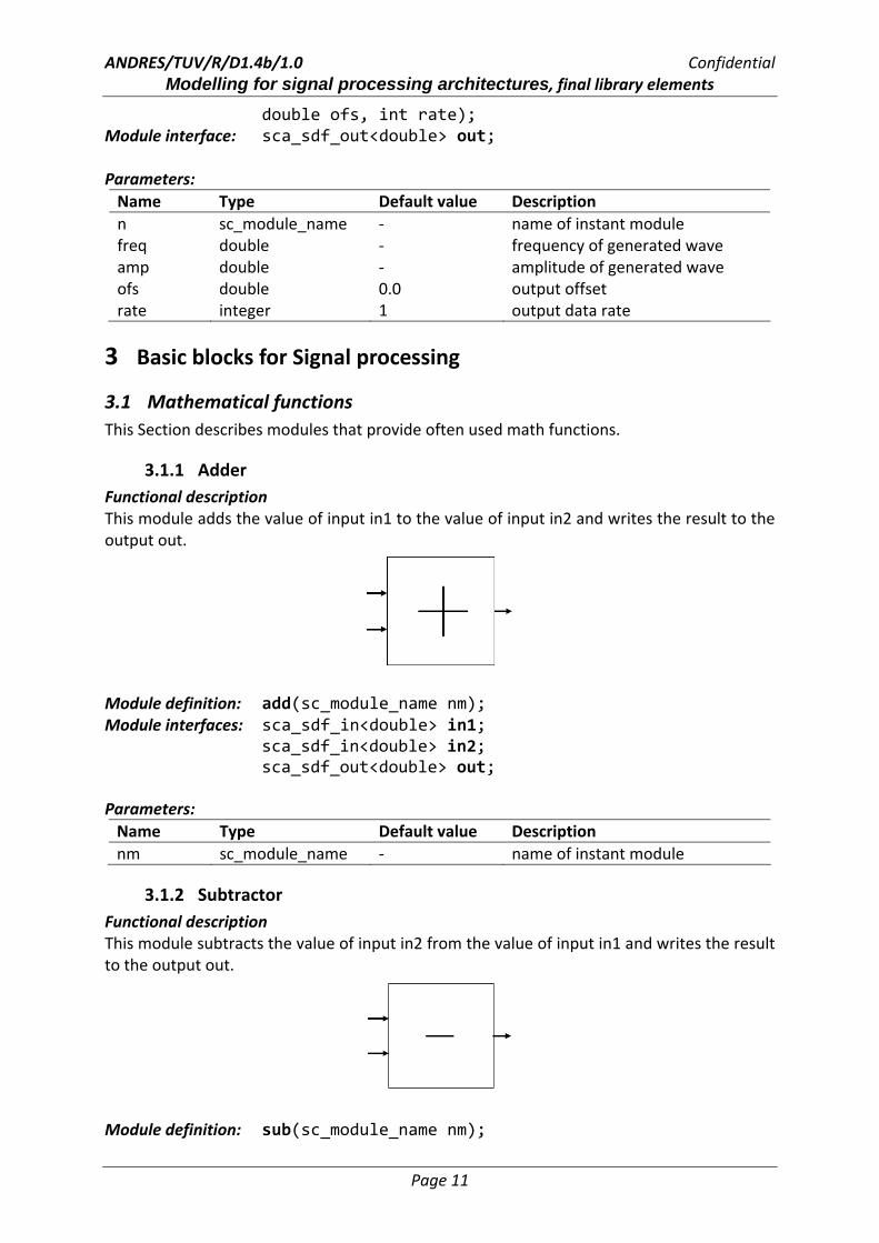
2.5 Square Wave Functional description The output of this module is a square wave. With the parameter “freq” and “amp” the user can define the frequency and the amplitude of the output signal. The parameter “ofs” is used to set the offset of the output signal.
out
Module definition: sqr_gen(sc_module_name n, double freq, double amp, double ofs, int rate);
sc_set_time_resolution(10.0, SC_NS); // set the time resolution /******** signals to connect different models **********/ sca_sdf_signal<double> sig_freq; // signal to transport the value of frequency sca_sdf_signal<double> sig_amp; // signal to transport the value of amplitude sca_sdf_signal<double> sig_out; // output signal
/******** model instantiation **********/
stim i_stim("stim"); // instantiate stimuli model i_stim.amp(sig_amp); i_stim.out(sig_freq);
sine sin("sin",1.0e3 , 1.0 , 0.0 , 0.0 , true , true , 1);
// instantiating sine model sin.freq_con(&sig_freq); sin.amp_con(&sig_amp); sin.out(sig_out); sin.out.set_T(100,SC_NS); // set the time step between two token drain drn("drn"); // instantiate drain to consume token drn.in(sig_out);

ANDRES/TUV/R/D1.4b/1.0 Confidential Modelling for signal processing architectures, final library elements
Page 10
Module interface: sca_sdf_out<double> out; Parameters: Name Type Default value Description n sc_module_name ‐ name of instant module freq double ‐ frequency of the generated wave amp double ‐ amplitude of the generated wave ofs double 0.0 output offset rate integer 1 output data rate
2.6 Triangle Wave Functional description The output of this module is a triangle wave. With the parameter “freq” and “amp” the user can define the frequency and the amplitude of the output signal. The parameter “ofs” is used to set the offset of the output signal.
out
Module definition: tri_gen(sc_module_name n, double freq, double amp, double ofs, int rate); Module interface: sca_sdf_out<double> out; Parameters: Name Type Default value Description n sc_module_name ‐ name of instant module freq double ‐ frequency of the generated wave amp double ‐ amplitude of the generated wave ofs double 0.0 output offset rate integer 1 output data rate
2.7 Saw tooth Wave Functional description The output of this module is a saw tooth wave. With the parameter “freq” and “amp” the user can define the frequency and the amplitude of the output signal. The parameter “ofs” is used to set the offset of the output signal.
Module definition: saw_gen(sc_module_name n, double freq, double amp,
ANDRES/TUV/R/D1.4b/1.0 Confidential Modelling for signal processing architectures, final library elements
Page 11
double ofs, int rate); Module interface: sca_sdf_out<double> out; Parameters: Name Type Default value Description n sc_module_name ‐ name of instant module freq double ‐ frequency of generated wave amp double ‐ amplitude of generated wave ofs double 0.0 output offset rate integer 1 output data rate
3 Basic blocks for Signal processing
3.1 Mathematical functions This Section describes modules that provide often used math functions.
3.1.1 Adder Functional description This module adds the value of input in1 to the value of input in2 and writes the result to the output out.
Module definition: add(sc_module_name nm); Module interfaces: sca_sdf_in<double> in1;
sca_sdf_in<double> in2; sca_sdf_out<double> out;
Parameters: Name Type Default value Description nm sc_module_name ‐ name of instant module
3.1.2 Subtractor Functional description This module subtracts the value of input in2 from the value of input in1 and writes the result to the output out.
Module definition: sub(sc_module_name nm);

ANDRES/TUV/R/D1.4b/1.0 Confidential Modelling for signal processing architectures, final library elements
Page 12
Module interfaces: sca_sdf_in<double> in1; sca_sdf_in<double> in2; sca_sdf_out<double> out;
Parameter: Name Type Default value Description nm sc_module_name ‐ name of instant module
3.1.3 Multiplier Functional description This module multiplies the value of input in1 to the value of input in2 and writes the result to the output out.
Module definition: mul(sc_module_name nm); Module interfaces: sca_sdf_in<double> in1;
sca_sdf_in<double> in2; sca_sdf_out<double> out;
Parameter: Name Type Default value Description nm sc_module_name ‐ name of instant module
3.1.4 Division Functional description This module divides the value of input in1 from the value of input in2 and writes the result to the output out.
Module definition: divi(sc_module_name nm); Module interfaces: sca_sdf_in<double> in1;
sca_sdf_in<double> in2; sca_sdf_out<double> out;
Parameter: Name Type Default value Description nm sc_module_name ‐ name of instant module

ANDRES/TUV/R/D1.4b/1.0 Confidential Modelling for signal processing architectures, final library elements
Page 13
3.1.5 Integrator Functional description This module integrates its input signal. An initial condition can be set with the parameter “_initial”.
Module definition: integ(sc_module_name nm, double _initial); Module interfaces: sca_sdf_in<double> in;
sca_sdf_out<double> out; Parameters: Name Type Default value Description nm sc_module_name ‐ name of instant module _initial double 0.0 initial condition
3.1.6 Logarithm Functional description This module calculates the logarithm for an applied input signal. The base of the logarithm can be set with the parameter “_base”.
Module definition: logarithm(sc_module_name n, string _base); Module interfaces: sca_sdf_in<double> in;
sca_sdf_out<double> out; Parameters: Name Type Default value Description n sc_module_name ‐ name of instant module _base string “10” base of the logarithm
3.1.7 Tan function Functional description This module implements the following function:
)tanh()( xxf = where x is the input signal of the module.
ANDRES/TUV/R/D1.4b/1.0 Confidential Modelling for signal processing architectures, final library elements
Page 14
Module definition: tang(sc_module_name n); Module interfaces: sca_sdf_in<double> in; sca_sdf_out<double> out; Parameter: Name Type Default value Description n sc_module_name ‐ name of instant module
3.2 Nonlinearities
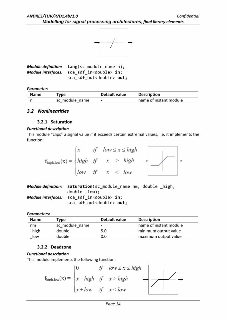
3.2.1 Saturation Functional description This module “clips” a signal value if it exceeds certain extremal values, i.e, it implements the function:
Module definition: saturation(sc_module_name nm, double _high,
double _low); Module interfaces: sca_sdf_in<double> in;
sca_sdf_out<double> out; Parameters: Name Type Default value Description nm sc_module_name ‐ name of instant module _high double 5.0 minimum output value _low double 0.0 maximum output value
3.2.2 Deadzone Functional description This module implements the following function:

ANDRES/TUV/R/D1.4b/1.0 Confidential Modelling for signal processing architectures, final library elements
Page 15
where x is the input signal of the module. Module definition: deadzone(sc_module_name nm, double _high,
double _low); Module interfaces: sca_sdf_in<double> in;
sca_sdf_out<double> out; Parameters: Name Type Default value Description nm sc_module_name ‐ name of instant module _high double 0.1 upper band limit _low double ‐0.1 Lower band limit
3.2.3 Coulomb function Functional description This module implements the Coulomb function which is defined as:
where x is the input signal of the module. Module definition: coulomb(sc_module_name nm, double _gain, double _y); Module interfaces: sca_sdf_in<double> in;
sca_sdf_out<double> out; Parameters: Name Type Default value Description nm sc_module_name ‐ name of instant module _gain double 1.0 factor _y double ‐0.1 point of the y‐intercept
3.3 Basic RF building blocks
3.3.1 Gain Functional description This module multiplies a constant factor (parameter “_gain”) to the input signal.
Module definition: gain(sc_module_name nm, double _gain);

ANDRES/TUV/R/D1.4b/1.0 Confidential Modelling for signal processing architectures, final library elements
Page 16
Module interfaces: sca_sdf_in<double> in; sca_sdf_out<double> out;
Parameters: Name Type Default value Description nm sc_module_name ‐ name of instant module _gain double 1.0 factor
3.3.2 Offset Functional description This module adds a constant offset value (parameter “_offset”) to the input value and writes the result to the output.
Module definition: offset(sc_module_name nm, double _offset); Module interfaces: sca_sdf_in<double> in;
sca_sdf_out<double> out; Parameters: Name Type Default value Description nm sc_module_name ‐ name of instant module _offset double 1.0 offset value
3.3.3 Quadrature Mixer Q_Mixer for transmitter Functional description This is an up conversion system which can be applied for I/Q signal systems. The User can set the initial frequency of the local oscillator using the parameter “_freq” and change it during simulation using the “freq_con” port. In this case the parameter “f_config” must be set to “true” during the instantiation of the module. Otherwise “freq_con” is not available. The amplitude of the carrier and the data rate of the in‐/output port can be set with the parameter “_amp” and “data_rate”, respectively.
Module definition: q_mixer_re(sc_module_name n,double _freq, double _amp, int data_rate, bool f_config);

ANDRES/TUV/R/D1.4b/1.0 Confidential Modelling for signal processing architectures, final library elements
Page 17
Module Interfaces: sca_sdf_out<double> out; // output of mixer sca_sdf_in<double> i_in; // input I signal sca_sdf_in<double> q_in; // input Q signal sca_sdf_in<double> freq_con; // optional input port // for frequency Parameters: Name Type Default value Description n sc_module_name ‐ name of instant module _freq double ‐ central frequency(initial
frequency of local oscillator) _amp double ‐ amplitude of the carrier data_rate integer 1 data rate of input and output
ports f_config bool false frequency configurability
Q_Mixer for receiver Functional description This is a down conversion system which can be applied for I/Q signal systems. The user can set the initial frequency of the local oscillator using the parameter “_freq” and change it during simulation using the “freq_con” port. In this case the parameter “f_config” must be set to “true” during the instantiation of the module. Otherwise “freq_con” is not available. The amplitude of the carrier and the data rate of the in‐/output port can be set with the parameter “_amp” and “data_rate”.
Module definition: q_mixer_re(sc_module_name n,double _freq, double _amp,int data_rate, bool f_config);
Module interfaces: sca_sdf_in<double> in; // input of mixer sca_sdf_out<double> i_out; // output of I signal sca_sdf_out<double> q_out; // output of Q signal sca_sdf_in<double> freq_con; // optional input port
// of frequency Parameters: Name Type Default value Description n sc_module_name ‐ name of instant module _freq double ‐ central frequency(initial frequency
of local oscillator) _amp double ‐ amplitude of the carrier data_rate integer 1 data rate of input and output
ports f_config bool false frequency configurability
ANDRES/TUV/R/D1.4b/1.0 Confidential Modelling for signal processing architectures, final library elements
Page 18
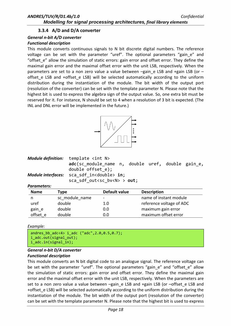
3.3.4 A/D and D/A converter General n‐bit A/D converter Functional description This module converts continuous signals to N bit discrete digital numbers. The reference voltage can be set with the parameter “uref”. The optional parameters “gain_e” and “offset_e” allow the simulation of static errors: gain error and offset error. They define the maximal gain error and the maximal offset error with the unit LSB, respectively. When the parameters are set to a non zero value a value between –gain_e LSB and +gain LSB (or –offset_e LSB and +offset_e LSB) will be selected automatically according to the uniform distribution during the instantiation of the module. The bit width of the output port (resolution of the converter) can be set with the template parameter N. Please note that the highest bit is used to express the algebra sign of the output value. So, one extra bit must be reserved for it. For instance, N should be set to 4 when a resolution of 3 bit is expected. (The INL and DNL error will be implemented in the future.)
Module definition: template <int N> adc(sc_module_name n, double uref, double gain_e, double offset_e);
Module interfaces: sca_sdf_in<double> in; sca_sdf_out<sc_bv<N> > out;
Parameters: Name Type Default value Description n sc_module_name ‐ name of instant module uref double 1.0 reference voltage of ADC gain_e double 0.0 maximum gain error offset_e double 0.0 maximum offset error
Example:
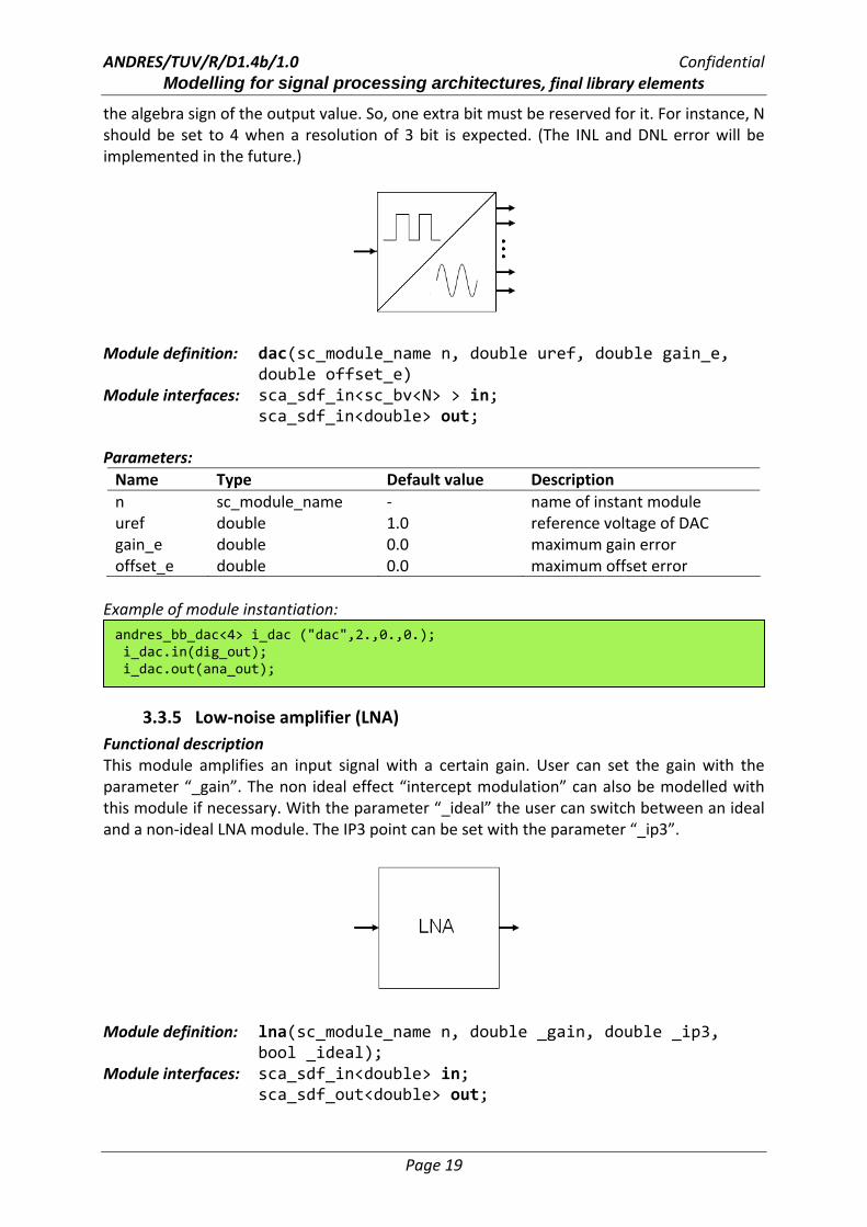
General n‐bit D/A converter Functional description This module converts an N bit digital code to an analogue signal. The reference voltage can be set with the parameter “uref”. The optional parameters “gain_e” and “offset_e” allow the simulation of static errors: gain error and offset error. They define the maximal gain error and the maximal offset error with the unit LSB, respectively. When the parameters are set to a non zero value a value between –gain_e LSB and +gain LSB (or –offset_e LSB and +offset_e LSB) will be selected automatically according to the uniform distribution during the instantiation of the module. The bit width of the output port (resolution of the converter) can be set with the template parameter N. Please note that the highest bit is used to express
andres_bb_adc<4> i_adc ("adc",2.0,0.5,0.7); i_adc.out(signal_out); i_adc.in(signal_in);
ANDRES/TUV/R/D1.4b/1.0 Confidential Modelling for signal processing architectures, final library elements
Page 19
the algebra sign of the output value. So, one extra bit must be reserved for it. For instance, N should be set to 4 when a resolution of 3 bit is expected. (The INL and DNL error will be implemented in the future.)
Module definition: dac(sc_module_name n, double uref, double gain_e, double offset_e) Module interfaces: sca_sdf_in<sc_bv<N> > in;
sca_sdf_in<double> out; Parameters: Name Type Default value Description n sc_module_name ‐ name of instant module uref double 1.0 reference voltage of DAC gain_e double 0.0 maximum gain error offset_e double 0.0 maximum offset error
Example of module instantiation:
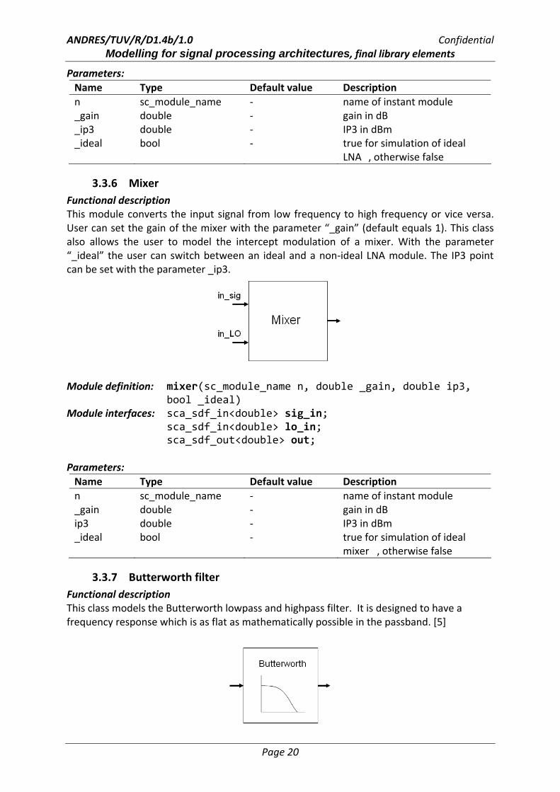
3.3.5 Low‐noise amplifier (LNA) Functional description This module amplifies an input signal with a certain gain. User can set the gain with the parameter “_gain”. The non ideal effect “intercept modulation” can also be modelled with this module if necessary. With the parameter “_ideal” the user can switch between an ideal and a non‐ideal LNA module. The IP3 point can be set with the parameter “_ip3”.
Module definition: lna(sc_module_name n, double _gain, double _ip3,
bool _ideal); Module interfaces: sca_sdf_in<double> in; sca_sdf_out<double> out;
andres_bb_dac<4> i_dac ("dac",2.,0.,0.); i_dac.in(dig_out); i_dac.out(ana_out);
ANDRES/TUV/R/D1.4b/1.0 Confidential Modelling for signal processing architectures, final library elements
Page 20
Parameters: Name Type Default value Description n sc_module_name ‐ name of instant module _gain double ‐ gain in dB _ip3 double ‐ IP3 in dBm _ideal bool ‐ true for simulation of ideal
LNA , otherwise false
3.3.6 Mixer Functional description This module converts the input signal from low frequency to high frequency or vice versa. User can set the gain of the mixer with the parameter “_gain” (default equals 1). This class also allows the user to model the intercept modulation of a mixer. With the parameter “_ideal” the user can switch between an ideal and a non‐ideal LNA module. The IP3 point can be set with the parameter _ip3.
Module definition: mixer(sc_module_name n, double _gain, double ip3,
bool _ideal) Module interfaces: sca_sdf_in<double> sig_in; sca_sdf_in<double> lo_in; sca_sdf_out<double> out; Parameters: Name Type Default value Description n sc_module_name ‐ name of instant module _gain double ‐ gain in dB ip3 double ‐ IP3 in dBm _ideal bool ‐ true for simulation of ideal
mixer , otherwise false
3.3.7 Butterworth filter Functional description This class models the Butterworth lowpass and highpass filter. It is designed to have a frequency response which is as flat as mathematically possible in the passband. [5]
ANDRES/TUV/R/D1.4b/1.0 Confidential Modelling for signal processing architectures, final library elements
Page 21
Module definition: btworth(sc_module_name n,string _type, double _gp, double _gs, double _wp, double _ws); Module interfaces: sca_sdf_in<double> in; sca_sdf_out<double> out; Parameters: Name Type Default value Description n sc_module_name ‐ name of instant module _type string ‐ select between lowpass and
highpass _gp double ‐ passband gain in dB _gs double ‐ stopband gain in dB _wp double ‐ passband frequency in rad/s _ws double ‐ stopband frequency in rad/s
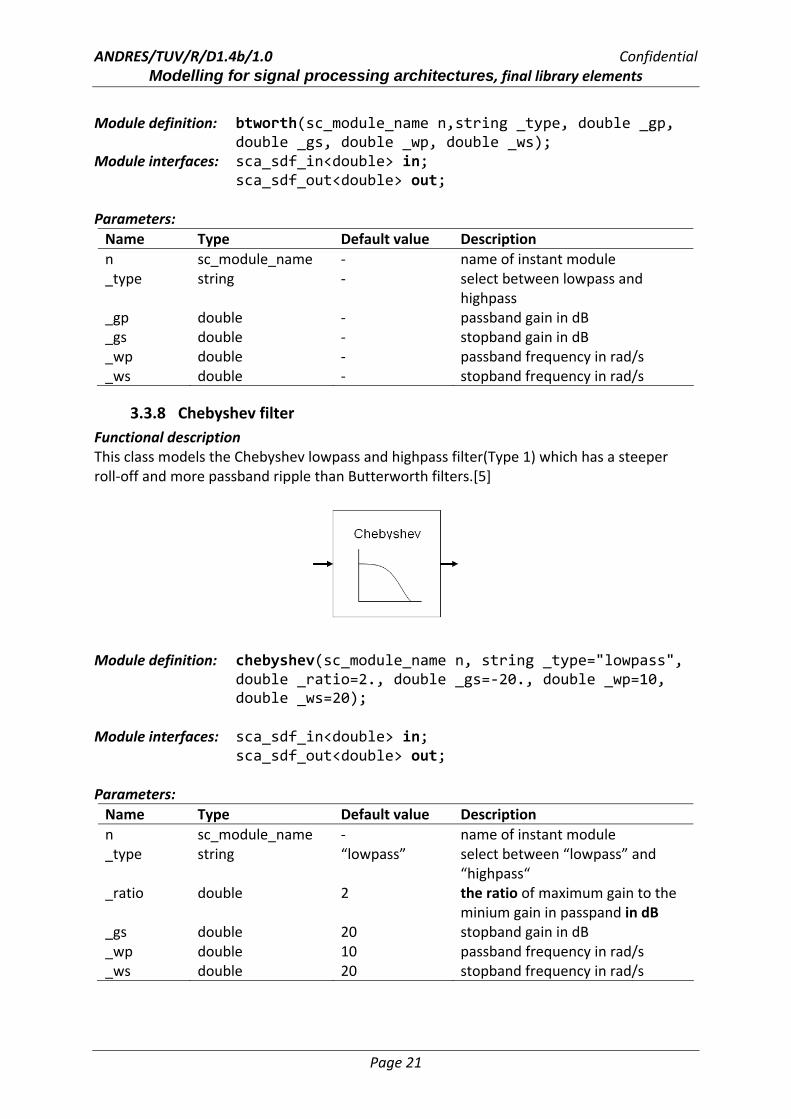
3.3.8 Chebyshev filter Functional description This class models the Chebyshev lowpass and highpass filter(Type 1) which has a steeper roll‐off and more passband ripple than Butterworth filters.[5]
Module definition: chebyshev(sc_module_name n, string _type="lowpass", double _ratio=2., double _gs=‐20., double _wp=10, double _ws=20); Module interfaces: sca_sdf_in<double> in; sca_sdf_out<double> out; Parameters: Name Type Default value Description n sc_module_name ‐ name of instant module _type string “lowpass” select between “lowpass” and
“highpass“ _ratio double 2 the ratio of maximum gain to the
minium gain in passpand in dB _gs double 20 stopband gain in dB _wp double 10 passband frequency in rad/s _ws double 20 stopband frequency in rad/s
ANDRES/TUV/R/D1.4b/1.0 Confidential Modelling for signal processing architectures, final library elements
Page 22
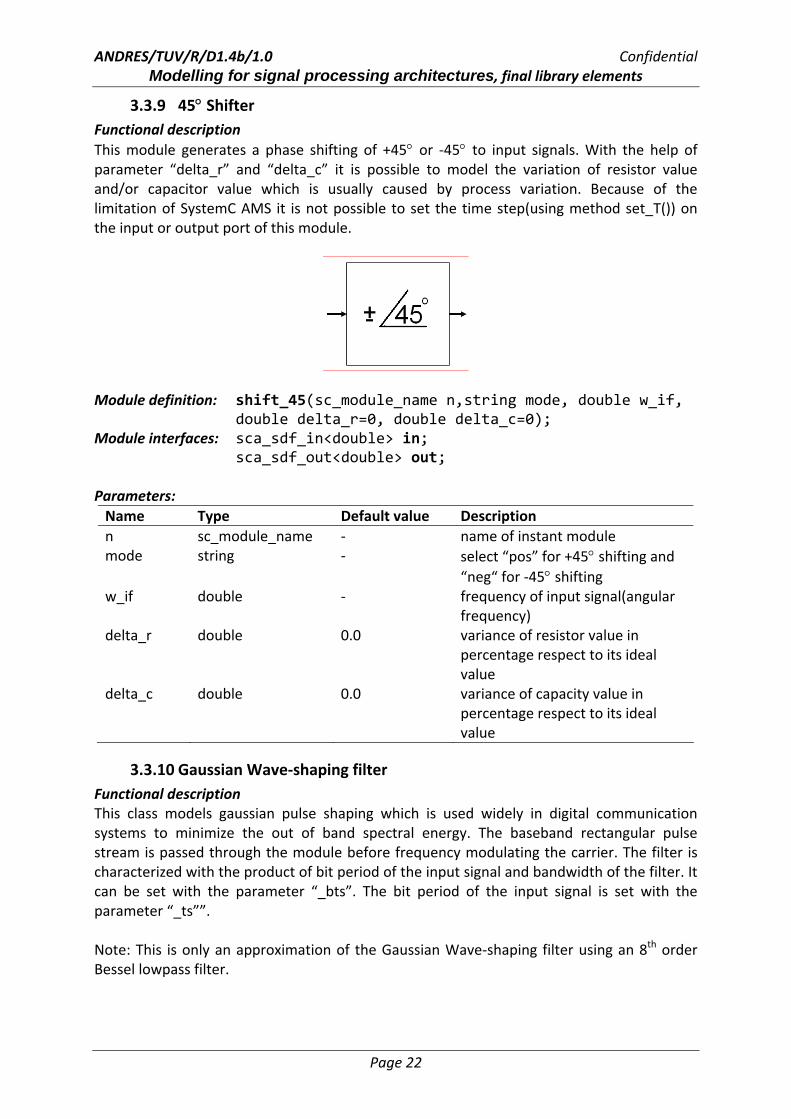
3.3.9 45° Shifter Functional description This module generates a phase shifting of +45° or ‐45° to input signals. With the help of parameter “delta_r” and “delta_c” it is possible to model the variation of resistor value and/or capacitor value which is usually caused by process variation. Because of the limitation of SystemC AMS it is not possible to set the time step(using method set_T()) on the input or output port of this module.
Module definition: shift_45(sc_module_name n,string mode, double w_if, double delta_r=0, double delta_c=0); Module interfaces: sca_sdf_in<double> in; sca_sdf_out<double> out; Parameters: Name Type Default value Description n sc_module_name ‐ name of instant module mode string ‐ select “pos” for +45° shifting and
“neg“ for ‐45° shifting w_if double ‐ frequency of input signal(angular
frequency) delta_r double 0.0 variance of resistor value in
percentage respect to its ideal value
delta_c double 0.0 variance of capacity value in percentage respect to its ideal value
3.3.10 Gaussian Wave‐shaping filter Functional description This class models gaussian pulse shaping which is used widely in digital communication systems to minimize the out of band spectral energy. The baseband rectangular pulse stream is passed through the module before frequency modulating the carrier. The filter is characterized with the product of bit period of the input signal and bandwidth of the filter. It can be set with the parameter “_bts”. The bit period of the input signal is set with the parameter “_ts””. Note: This is only an approximation of the Gaussian Wave‐shaping filter using an 8th order Bessel lowpass filter.

ANDRES/TUV/R/D1.4b/1.0 Confidential Modelling for signal processing architectures, final library elements
Page 23
Module definition: gauss_shaping(sc_module_name n, double _bts,
double _ts); Module interfaces: sca_sdf_in<double> in; sca_sdf_out<double> out; Parameters: Name Type Default value Description n sc_module_name ‐ name of instant module _bts double ‐ product of bit period of input
signal and ‐3dB bandwidth of the Gaussian filter
_ts double ‐ bit period of input stream
3.3.11 Digital VCO Functional description This class models a digital voltage controlled oscillator. It is used to generate a single‐tone square wave with tunable frequency. Tuning is done using a control voltage at the input in. Without an input voltage the oscillator runs at its free running frequency which can be set with the parameter “freq_data” during the instantiation of the module. Sensitivity and gain of the VCO can be set with the parameters “_kvco” and “_gain”. Besides, it is possible to increase the data rate of the output port with the parameter “data_rate”.
Module definition: d_vco(sc_module_name n, double freq_data,
int datarate, double _kvco, double _gain) Module interfaces: sca_sdf_in<double> in; sca_sdf_out<double> out; Parameters: Name Type Default value Description n sc_module_name ‐ name of instant module freq_data double ‐ central(free running) frequency data_rate integer ‐ datarate of the output _kvco double ‐ sensitivity _gain double ‐ gain
ANDRES/TUV/R/D1.4b/1.0 Confidential Modelling for signal processing architectures, final library elements
Page 24
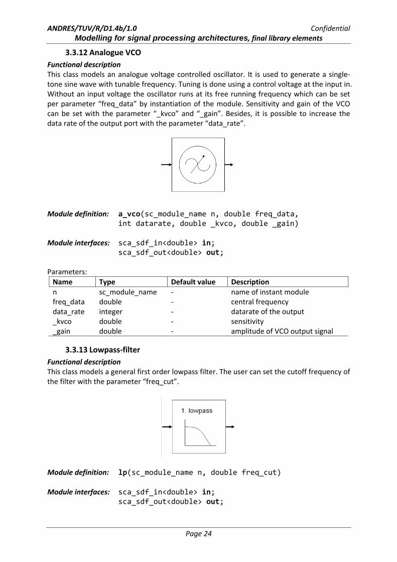
3.3.12 Analogue VCO Functional description This class models an analogue voltage controlled oscillator. It is used to generate a single‐tone sine wave with tunable frequency. Tuning is done using a control voltage at the input in. Without an input voltage the oscillator runs at its free running frequency which can be set per parameter “freq_data” by instantiation of the module. Sensitivity and gain of the VCO can be set with the parameter “_kvco” and “_gain”. Besides, it is possible to increase the data rate of the output port with the parameter “data_rate”.
Module definition: a_vco(sc_module_name n, double freq_data, int datarate, double _kvco, double _gain)
Module interfaces: sca_sdf_in<double> in; sca_sdf_out<double> out; Parameters: Name Type Default value Description n sc_module_name ‐ name of instant module freq_data double ‐ central frequency data_rate integer ‐ datarate of the output _kvco double ‐ sensitivity _gain double ‐ amplitude of VCO output signal
3.3.13 Lowpass‐filter Functional description This class models a general first order lowpass filter. The user can set the cutoff frequency of the filter with the parameter “freq_cut”.
Module definition: lp(sc_module_name n, double freq_cut) Module interfaces: sca_sdf_in<double> in; sca_sdf_out<double> out;
ANDRES/TUV/R/D1.4b/1.0 Confidential Modelling for signal processing architectures, final library elements
Page 25
Parameters: Name Type Default value Description n sc_module_name ‐ name of instant module freq_cut double ‐ cutoff frequency of filter
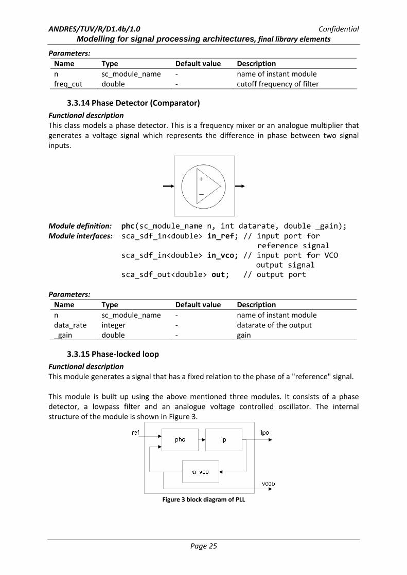
3.3.14 Phase Detector (Comparator) Functional description This class models a phase detector. This is a frequency mixer or an analogue multiplier that generates a voltage signal which represents the difference in phase between two signal inputs.
Module definition: phc(sc_module_name n, int datarate, double _gain); Module interfaces: sca_sdf_in<double> in_ref; // input port for reference signal sca_sdf_in<double> in_vco; // input port for VCO output signal sca_sdf_out<double> out; // output port Parameters: Name Type Default value Description n sc_module_name ‐ name of instant module data_rate integer ‐ datarate of the output _gain double ‐ gain
3.3.15 Phase‐locked loop Functional description This module generates a signal that has a fixed relation to the phase of a "reference" signal. This module is built up using the above mentioned three modules. It consists of a phase detector, a lowpass filter and an analogue voltage controlled oscillator. The internal structure of the module is shown in Figure 3.
Figure 3 block diagram of PLL
ANDRES/TUV/R/D1.4b/1.0 Confidential Modelling for signal processing architectures, final library elements
Page 26
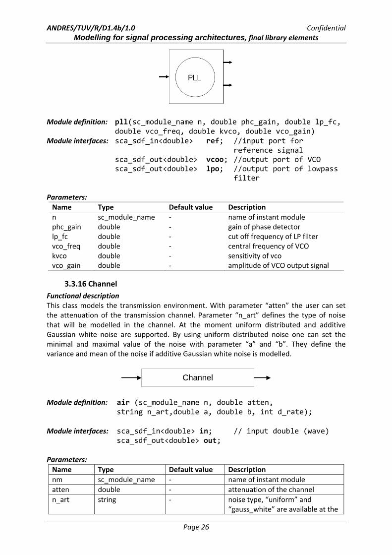
Module definition: pll(sc_module_name n, double phc_gain, double lp_fc, double vco_freq, double kvco, double vco_gain)
Module interfaces: sca_sdf_in<double> ref; //input port for reference signal sca_sdf_out<double> vcoo; //output port of VCO sca_sdf_out<double> lpo; //output port of lowpass filter Parameters: Name Type Default value Description n sc_module_name ‐ name of instant module phc_gain double ‐ gain of phase detector lp_fc double ‐ cut off frequency of LP filter vco_freq double ‐ central frequency of VCO kvco double ‐ sensitivity of vco vco_gain double ‐ amplitude of VCO output signal
3.3.16 Channel Functional description This class models the transmission environment. With parameter “atten” the user can set the attenuation of the transmission channel. Parameter “n_art” defines the type of noise that will be modelled in the channel. At the moment uniform distributed and additive Gaussian white noise are supported. By using uniform distributed noise one can set the minimal and maximal value of the noise with parameter “a” and “b”. They define the variance and mean of the noise if additive Gaussian white noise is modelled.
Channel
Module definition: air (sc_module_name n, double atten,
string n_art,double a, double b, int d_rate); Module interfaces: sca_sdf_in<double> in; // input double (wave)
sca_sdf_out<double> out; Parameters: Name Type Default value Description nm sc_module_name ‐ name of instant module atten double ‐ attenuation of the channel n_art string ‐ noise type, “uniform” and
“gauss_white” are available at the

ANDRES/TUV/R/D1.4b/1.0 Confidential Modelling for signal processing architectures, final library elements
Page 27
moment a double ‐ The parameter defines the
minimal value of noise when “n_art” is set to “uniform” and defines the variance of noise if “n_art” is set to “gauss_white”
b double ‐ The parameter defines the maximal value of noise when “n_art” is set to “uniform” and defines the mean of noise if “n_art” is set to “gauss_white”
d_rate int ‐ data rate of input and output signal
3.4 Modulation/Demodulation This Section describes modules for modulation and demodulation of signals.
3.4.1 Amplitude Modulation Functional description This module modulates the amplitude of the carrier signal with the input signal. The carrier frequency and the amplitude can be set with parameters “_freq” and “_ampl”. The parameter “_offset” adds a constant value to the input signal. It is possible to increase the output data rate with the “_rate” parameter.
Module definition: mod_am(sc_module_name nm, double _freq, double _ampl,
double _offset, int _rate) ; Module interfaces: sca_sdf_in<double> in;
sca_sdf_out<double> out; Parameters: Name Type Default value Description nm sc_module_name ‐ name of instant module _freq double ‐ carrier frequency _ampl double 1.0 carrier amplitude _offset double 0.0 output offset _rate integer 1 data rate of output port
3.4.2 Binary Amplitude Shift Keying (BASK) Modulator Functional description
ANDRES/TUV/R/D1.4b/1.0 Confidential Modelling for signal processing architectures, final library elements
Page 28
This module modulates the carrier with an input bit stream using binary amplitude shift keying. Carrier amplitudes correspond to binary input 1 and 0 can be set per parameter “_ampl1” and “_ampl0”, respectively. Besides, user can set frequency and initial phase of the carrier with parameter “_freq” and “_phi”.
Module definition: mod_bask(sc_module_name nm, double _freq, double _ampl1, double _ampl0, double _phi, int _rate) ;
Module interfaces: sca_sdf_in<bool> in; sca_sdf_out<double> out;
Parameters: Name Type Default value Description nm sc_module_name ‐ name of instant module _freq double ‐ carrier frequency _ampl1 double 1.0 carrier amplitude if input is 1 _ampl0 double 0.0 carrier amplitude of input is 0 _phi double 0.0 initial phase of carrier _rate integer 1 data rate of output port
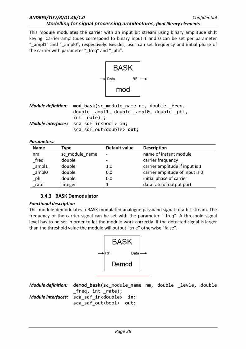
3.4.3 BASK Demodulator Functional description This module demodulates a BASK modulated analogue passband signal to a bit stream. The frequency of the carrier signal can be set with the parameter “_freq”. A threshold signal level has to be set in order to let the module work correctly. If the detected signal is larger than the threshold value the module will output “true” otherwise “false”.
Module definition: demod_bask(sc_module_name nm, double _levle, double
_freq, int _rate); Module interfaces: sca_sdf_in<double> in; sca_sdf_out<bool> out;

ANDRES/TUV/R/D1.4b/1.0 Confidential Modelling for signal processing architectures, final library elements
Page 29
Parameters: Name Type Default value Description nm sc_module_name ‐ name of instant module _level double ‐ threshold signal level _freq double 1000.0 carrier frequency _rate integer 1 data rate of input port
3.4.4 Binary Phase Shift Keying (BPSK) Modulator Functional description This module modulates an input bit stream onto a carrier using binary phase shift keying. Frequency of the carrier and data rate of output port can be set with parameter “_freq” and “_out_rate”. Amplitude and initial phase of the carrier are set to 1.0 and 0.0 by default and can not be changed.
Module definition: bpsk(sc_module_name n, double _freq=1000,
int _out_rate=1); Module interfaces: sca_sdf_in<bool> in; sca_sdf_out<double> out; Parameters: Name Type Default value Description n sc_module_name ‐ name of instant module _freq double 1000.0 carrier frequency _out_rate integer 1 data rate of output port
3.4.5 BPSK Demodulator Functional description This module demodulates a BPSK modulated signal to a bit stream. Frequency of the carrier and data rate of the input port can be set with the parameters “_freq” and “_in_rate”.
Module definition: bpsk_de(sc_module_name n,double _freq,int _in_rate); Module Interfaces: sca_sdf_in<double> in; sca_sdf_out<bool> out;
ANDRES/TUV/R/D1.4b/1.0 Confidential Modelling for signal processing architectures, final library elements
Page 30
Parameters: Name Type Default value Description n sc_module_name ‐ name of instant module _freq double 1000.0 carrier frequency _in_rate integer 1 data rate of input port
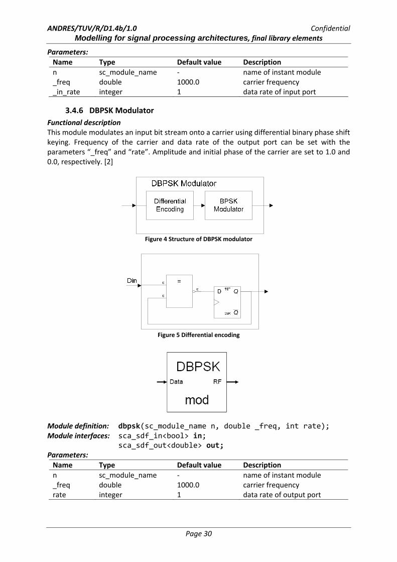
3.4.6 DBPSK Modulator Functional description This module modulates an input bit stream onto a carrier using differential binary phase shift keying. Frequency of the carrier and data rate of the output port can be set with the parameters “_freq” and “rate”. Amplitude and initial phase of the carrier are set to 1.0 and 0.0, respectively. [2]
Figure 4 Structure of DBPSK modulator
Figure 5 Differential encoding
Module definition: dbpsk(sc_module_name n, double _freq, int rate); Module interfaces: sca_sdf_in<bool> in; sca_sdf_out<double> out; Parameters: Name Type Default value Description n sc_module_name ‐ name of instant module _freq double 1000.0 carrier frequency rate integer 1 data rate of output port
ANDRES/TUV/R/D1.4b/1.0 Confidential Modelling for signal processing architectures, final library elements
Page 31
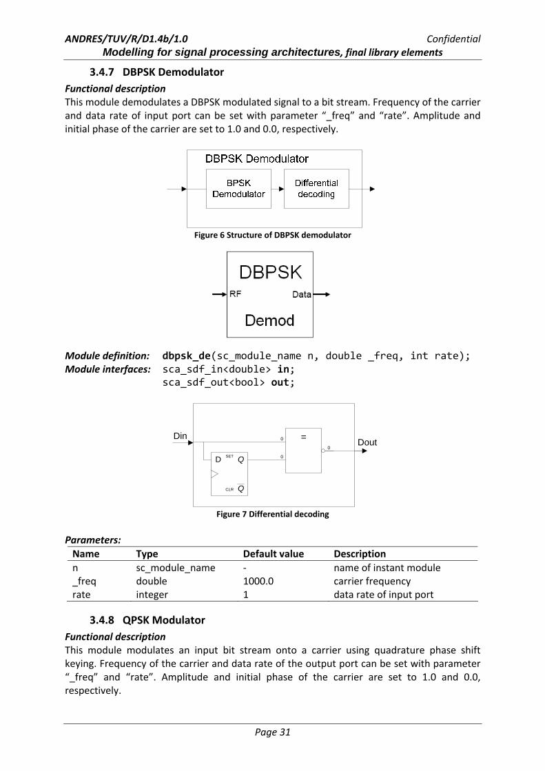
3.4.7 DBPSK Demodulator Functional description This module demodulates a DBPSK modulated signal to a bit stream. Frequency of the carrier and data rate of input port can be set with parameter “_freq” and “rate”. Amplitude and initial phase of the carrier are set to 1.0 and 0.0, respectively.
Figure 6 Structure of DBPSK demodulator
Module definition: dbpsk_de(sc_module_name n, double _freq, int rate); Module interfaces: sca_sdf_in<double> in; sca_sdf_out<bool> out;
=0
0
0
Q
QSET
CLR
D
DinDout
Figure 7 Differential decoding
Parameters: Name Type Default value Description n sc_module_name ‐ name of instant module _freq double 1000.0 carrier frequency rate integer 1 data rate of input port
3.4.8 QPSK Modulator Functional description This module modulates an input bit stream onto a carrier using quadrature phase shift keying. Frequency of the carrier and data rate of the output port can be set with parameter “_freq” and “rate”. Amplitude and initial phase of the carrier are set to 1.0 and 0.0, respectively.

ANDRES/TUV/R/D1.4b/1.0 Confidential Modelling for signal processing architectures, final library elements
Page 32
90o
S/P Converter LO
Figure 8 Structure of QPSK modulator
Module definition: qpsk(sc_module_name n, double _freq, int rate); Module interfaces: sca_sdf_in<bool> in;
sca_sdf_out<double> out; Parameters: Name Type Default value Description nm sc_module_name ‐ name of instant module _freq double 1000.0 carrier frequency rate integer 1 data rate of output port
3.4.9 QPSK Demodulator Functional description This module demodulates a QPSK modulated signal to a bit stream. Frequency of the carrier and data rate of the input port can be set with the parameter “_freq” and “rate”. Amplitude and initial phase of the carrier are set to 1.0 and 0.0, respectively.
Figure 9 QPSK demodulator

ANDRES/TUV/R/D1.4b/1.0 Confidential Modelling for signal processing architectures, final library elements
Page 33
Module definition: qpsk_de(sc_module_name n, double _freq, int rate); Module interfaces: sca_sdf_in<double> in; sca_sdf_out<bool> out; Paramenters: Name Type Default value Description n sc_module_name ‐ name of instant module _freq double 1000.0 carrier frequency rate integer 1 data rate of input port
3.4.10 Offset QPSK (OQPSK) Modulator Functional description This class modulates an input bit stream onto a carrier using offset quadrature phase shift keying. Frequency of the carrier and data rate of output port can be set with the parameter “_freq” and “rate”.
90o
S/P Converter LO
Tb
Figure 10 Structure of Offset OPSK modulator
As shown in Figure 10 the data streams are delayed by half the symbol period after the S/P conversion, so simultaneous transitions in waveforms at nodes A and B are avoided. The phase step is therefore only +/‐ 90o. Module definition: oqpsk(sc_module_name n, double _freq, int rate); Module interfaces: sca_sdf_in<bool> in;
sca_sdf_out<double> out; Parameters: Name Type Default value Description n sc_module_name ‐ name of instant module _freq double 1000.0 carrier frequency rate integer 1 data rate of output port
3.4.11 OQPSK Demodulator Functional description

ANDRES/TUV/R/D1.4b/1.0 Confidential Modelling for signal processing architectures, final library elements
Page 34
This module demodulates an OQPSK modulated signal to a bit stream. Frequency of the carrier and data rate of the input port can be set with the parameter “_freq” and “rate”.
Module definition: oqpsk_de(sc_module_name n, double _freq, int rate); Module interfaces: sca_sdf_in<double> in; sca_sdf_out<bool> out; Parameters: Name Type Default value Description n sc_module_name ‐ name of instant module _freq double 1000.0 carrier frequency rate integer 1 data rate of input port
3.4.12 DQPSK Modulator Functional description This module modulates an input bit stream onto a carrier using differential quadrature phase shift keying. Frequency of the carrier and data rate of the output port can be set with the parameter “_freq” and “rate”.
Module definition: dqpsk(sc_module_name n, double _freq, int rate); Module interfaces: sca_sdf_in<bool> in;
sca_sdf_out<double> out; Parameters: Name Type Default value Description nm sc_module_name ‐ name of instant module _freq double 1000.0 carrier frequency rate integer 1 data rate of output port
3.4.13 DQPSK Demodulator Functional description This module demodulates a DQPSK modulated signal to a bit stream. Frequency of the carrier and data rate of input port can be set with the parameter “_freq” and “rate”.
ANDRES/TUV/R/D1.4b/1.0 Confidential Modelling for signal processing architectures, final library elements
Page 35
Module definition: dqpsk_de(sc_module_name n, double _freq, int rate); Module interfaces: sca_sdf_in<double> in; sca_sdf_out<bool> out; Parameters: Name Type Default value Description n sc_module_name ‐ name of instant module _freq double 1000.0 carrier frequency rate integer 1 data rate of input port
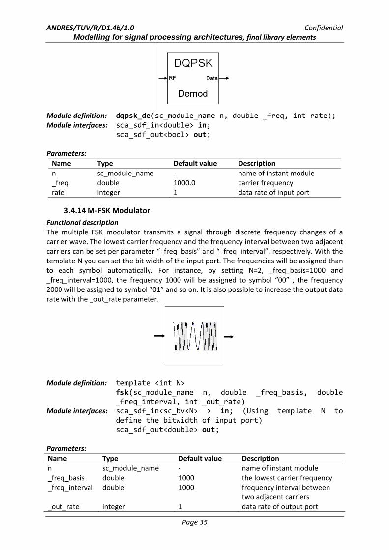
3.4.14 M‐FSK Modulator Functional description The multiple FSK modulator transmits a signal through discrete frequency changes of a carrier wave. The lowest carrier frequency and the frequency interval between two adjacent carriers can be set per parameter “_freq_basis” and “_freq_interval”, respectively. With the template N you can set the bit width of the input port. The frequencies will be assigned than to each symbol automatically. For instance, by setting N=2, _freq_basis=1000 and _freq_interval=1000, the frequency 1000 will be assigned to symbol “00” , the frequency 2000 will be assigned to symbol “01” and so on. It is also possible to increase the output data rate with the _out_rate parameter.
Module definition: template <int N>
fsk(sc_module_name n, double _freq_basis, double _freq_interval, int _out_rate)
Module interfaces: sca_sdf_in<sc_bv<N> > in; (Using template N to define the bitwidth of input port) sca_sdf_out<double> out;
Parameters: Name Type Default value Description n sc_module_name ‐ name of instant module _freq_basis double 1000 the lowest carrier frequency _freq_interval double 1000 frequency interval between
two adjacent carriers _out_rate integer 1 data rate of output port

ANDRES/TUV/R/D1.4b/1.0 Confidential Modelling for signal processing architectures, final library elements
Page 36
Example of module instantiation:
In this example a fsk modulator with 4 bits wide input port is instantiated. The lowest carrier frequency and frequency interval are set to 1000 and 500, respectively.
3.4.15 M‐PSK Modulator Functional description The multiple PSK modulator conveys data by changing, or modulating, the phase of a reference signal (the carrier wave). The carrier frequency can be set per parameter “_freq”. With the template parameter N you can set the bit width of the input port. The phases will be assigned than to each symbol automatically.
Module definition: template <int N>
psk(sc_module_name n, double _freq, int _out_rate=1) Module interfaces: sca_sdf_in<sc_bv<N> > in; sca_sdf_out<double> out; Parameters: Name Type Default value Description n sc_module_name ‐ name of instant module _freq double ‐ carrier frequency _out_rate integer 1 data rate of output port Example of module instantiation:
In this example a psk modulator with 4 bits wide input port is instantiated. Phase “162π⋅i ”
will be assigned to the ith symbol.
3.4.16 QAM Mapper Functional description This module maps an input bit stream to a rectangular IQ constellation. 4, 16, 64 and 256 point constellations are implemented. The data rate of the output is 2 (resp. 4, 6, 8) times
psk<4> i_psk("psk",1000,1); i_psk.in(sig_stim); i_psk.out(sig_out);
fsk<4> i_fsk("fsk",1000,500,1); i_fsk.in(sig_stim); i_fsk.out(sig_out);

ANDRES/TUV/R/D1.4b/1.0 Confidential Modelling for signal processing architectures, final library elements
Page 37
smaller then the data rate of the input. At the moment it is not possible to define arbitrary QAM constellations. This will be implemented in the future.
Module definition: qam_map(sc_module_name nm, int _rate); Module interfaces: sca_sdf_in<bool> in;
sca_sdf_out<double> out_i; sca_sdf_out<double> out_q;
Parameters: Name Type Default value Description nm sc_module_name ‐ name of instant module _rate integer 4 number of points in the
constellation (4,16,64,256)
3.4.17 QAM Demapper Functional description This module maps a pair of double value inputs, namely I and Q signal, per a rectangular IQ constellation to an output bit stream. 4, 16, 64 and 256 point constellations are implemented. The data rate of the input is 2 (resp. 4, 6, 8) times smaller then the data rate of the output. At the moment it is not possible to define arbitrary QAM constellations. This will be implemented in the future.
Module definition: qam_demap(sc_module_name nm, int _rate); Module interfaces: sca_sdf_in<double> in_i;
sca_sdf_in<double> in_q; sca_sdf_in<bool> out;
Parameters: Name Type Default value Description nm sc_module_name ‐ name of instant module _rate integer 4 number of points in the
constellation (4,16,64,256)
ANDRES/TUV/R/D1.4b/1.0 Confidential Modelling for signal processing architectures, final library elements
Page 38
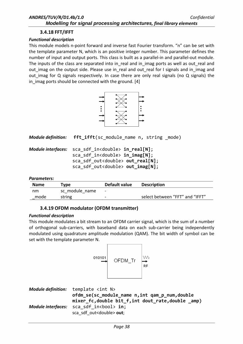
3.4.18 FFT/IFFT Functional description This module models n‐point forward and inverse fast Fourier transform. “n” can be set with the template parameter N, which is an positive integer number. This parameter defines the number of input and output ports. This class is built as a parallel‐in and parallel‐out module. The inputs of the class are separated into in_real and in_imag ports as well as out_real and out_imag on the output side. Please use in_real and out_real for I signals and in_imag and out_imag for Q signals respectively. In case there are only real signals (no Q signals) the in_imag ports should be connected with the ground. [4]
Module definition: fft_ifft(sc_module_name n, string _mode) Module interfaces: sca_sdf_in<double> in_real[N]; sca_sdf_in<double> in_imag[N]; sca_sdf_out<double> out_real[N]; sca_sdf_out<double> out_imag[N]; Parameters: Name Type Default value Description nm sc_module_name ‐ _mode string ‐ select between “FFT” and “IFFT”
3.4.19 OFDM modulator (OFDM transmitter) Functional description This module modulates a bit stream to an OFDM carrier signal, which is the sum of a number of orthogonal sub‐carriers, with baseband data on each sub‐carrier being independently modulated using quadrature amplitude modulation (QAM). The bit width of symbol can be set with the template parameter N.
Module definition: template <int N> ofdm_se(sc_module_name n,int qam_p_num,double mixer_fc,double bit_f,int dout_rate,double _amp)
Module interfaces: sca_sdf_in<bool> in; sca_sdf_out<double> out;

ANDRES/TUV/R/D1.4b/1.0 Confidential Modelling for signal processing architectures, final library elements
Page 39
Parameters: Name Type Default value Description nm sc_module_name ‐ name of instant module qam_p_num integer ‐ number of points in the
constellation mixer_fc double ‐ carrier frequency bit_f double ‐ frequency of input bit stream data_rate integer ‐ data rate of output port _ampl double 1.0 amplitude of carrier wave data_rate: note that this data rate can basically be set independently. But a value too low would result in an undesirable outcome regarding Nyquist’s sampling theorem. With this parameter the user can set the number of tokens contained in one period of the carrier signal.
3.4.20 OFDM demodulator (OFDM Receiver) Functional description This module demodulates an OFDM carrier signal to a bit stream. The bit width of symbol can be set with the template parameter N.
Module definition: template <int N> ofdm_re(sc_module_name n, double mixer_fc, int demap_p,double bit_f,int dout_rate,double _amp)
Module interfaces: sca_sdf_in<double> in;
sca_sdf_out<bool> out; Parameter Type Default value Description nm sc_module_name ‐ name of instant module mixer_fc double ‐ carrier frequency demap_p integer ‐ number of points in the
constellation. This value should equal to the qam_p_num by transmitter.
bit_f integer ‐ frequency of input bit stream. This value should equal to the bit_f by transmitter.
data_rate integer ‐ data rate of input port. This value should equal to the data_rate by transmitter.
_ampl double ‐ amplitude of carrier wave

ANDRES/TUV/R/D1.4b/1.0 Confidential Modelling for signal processing architectures, final library elements
Page 40
3.5 Miscellaneous
3.5.1 Up‐Sample Functional description This module increases the data rate of the input signal. It reads one value and writes it “_rate” times to the output.
Module definition: upsample(sc_module_name nm, int _rate); Module interfaces: sca_sdf_in<double> in; sca_sdf_out<double> out; Parameters: Name Type Default value Description nm sc_module_name ‐ name of instant module _rate integer 1 data rate of output port
3.5.2 Down‐Sample Functional description This module decreases the data rate of the input signal. It reads “_rate” values and writes one value to the output. With the parameter “_sel” it is possible to select the data which you want to write to the output port. It is an integer number between 1 and “_rate”.
Module definition: downsample(sc_module_name nm, int _sel, int _rate); Module interfaces: sca_sdf_in<double> in; sca_sdf_out<double> out; Parameters: Name Type Default value Description nm sc_module_name ‐ name of instant module _sel integer 1 select the _sel‐th token of the
input token _rate integer 1 data rate of input port
ANDRES/TUV/R/D1.4b/1.0 Confidential Modelling for signal processing architectures, final library elements
Page 41
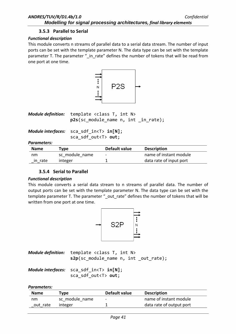
3.5.3 Parallel to Serial Functional description This module converts n streams of parallel data to a serial data stream. The number of input ports can be set with the template parameter N. The data type can be set with the template parameter T. The parameter “_in_rate” defines the number of tokens that will be read from one port at one time.
Module definition: template <class T, int N> p2s(sc_module_name n, int _in_rate);
Module interfaces: sca_sdf_in<T> in[N]; sca_sdf_out<T> out; Parameters: Name Type Default value Description nm sc_module_name ‐ name of instant module _in_rate integer 1 data rate of input port
3.5.4 Serial to Parallel Functional description This module converts a serial data stream to n streams of parallel data. The number of output ports can be set with the template parameter N. The data type can be set with the template parameter T. The parameter “_out_rate” defines the number of tokens that will be written from one port at one time.
Module definition: template <class T, int N>
s2p(sc_module_name n, int _out_rate); Module interfaces: sca_sdf_in<T> in[N]; sca_sdf_out<T> out; Parameters: Name Type Default value Description nm sc_module_name ‐ name of instant module _out_rate integer 1 data rate of output port
ANDRES/TUV/R/D1.4b/1.0 Confidential Modelling for signal processing architectures, final library elements
Page 42
3.5.5 Signal splitter Functional description With this module the user can easily copy the input signal to several output ports. The signal type (bool, double etc.) and the number of output ports can be set with the template parameters T and N, respectively.
Module definition: template <class T, int N> splitter(sc_module_name n) Module interfaces: sca_sdf_in<T> in; sca_sdf_out<T> out[N]; Parameters: Name Type Default value Description nm sc_module_name ‐ name of instant module
4 Signal analysis units
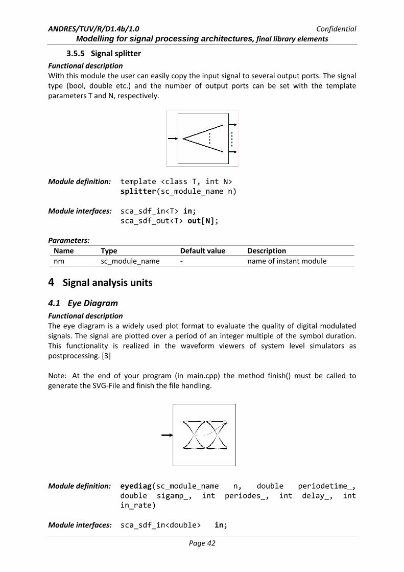
4.1 Eye Diagram Functional description The eye diagram is a widely used plot format to evaluate the quality of digital modulated signals. The signal are plotted over a period of an integer multiple of the symbol duration. This functionality is realized in the waveform viewers of system level simulators as postprocessing. [3] Note: At the end of your program (in main.cpp) the method finish() must be called to generate the SVG‐File and finish the file handling.
Module definition: eyediag(sc_module_name n, double periodetime_,
double sigamp_, int periodes_, int delay_, int in_rate)
Module interfaces: sca_sdf_in<double> in;

ANDRES/TUV/R/D1.4b/1.0 Confidential Modelling for signal processing architectures, final library elements
Page 43
Parameters: Name Type Default value Description n sc_module_name ‐ name of instant module periodetime_ double ‐ symbol duration of original sigal sigamp_ double ‐ maximal possible amplitude of
signal to be analysed periodes_ integer ‐ number of periods to be plotted delay_ integer ‐ number of periods to be ignored
before plot in_rate integer 10 data rate of input port
4.2 Scatter Plot Functional description This module plots the scatter diagram of an input signal. Note: At the end of your program (in main.cpp) the method finish() must be called to generate the SVG‐File and finish the file handling.
Module definition: scatter(sc_module_name n, double sigamp_,
int in_rate) Module interfaces: sca_sdf_in<double> in; Parameters: Name Type Default value Description n sc_module_name ‐ name of instant module sigamp_ double ‐ maximal possible amplitude of
signal to be analysed in_rate integer 10 data rate of input port
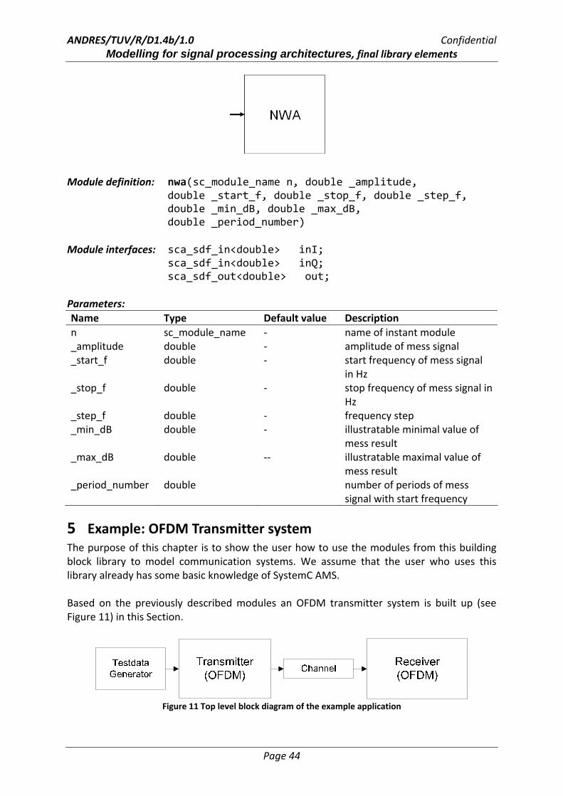
4.3 Network analyzer Functional description This class modules a network analyzer which is used to analyze the frequency response of electrical networks. Note: At the end of your program (in main.cpp) the method finish() must be called to generate the SVG‐File and finish the file handling.
ANDRES/TUV/R/D1.4b/1.0 Confidential Modelling for signal processing architectures, final library elements
Page 44
Module definition: nwa(sc_module_name n, double _amplitude,
double _start_f, double _stop_f, double _step_f, double _min_dB, double _max_dB, double _period_number)
Module interfaces: sca_sdf_in<double> inI; sca_sdf_in<double> inQ;
sca_sdf_out<double> out; Parameters: Name Type Default value Description n sc_module_name ‐ name of instant module _amplitude double ‐ amplitude of mess signal _start_f double ‐ start frequency of mess signal
in Hz _stop_f double ‐ stop frequency of mess signal in
Hz _step_f double ‐ frequency step _min_dB double ‐ illustratable minimal value of
mess result _max_dB double ‐‐ illustratable maximal value of
mess result _period_number double number of periods of mess
signal with start frequency
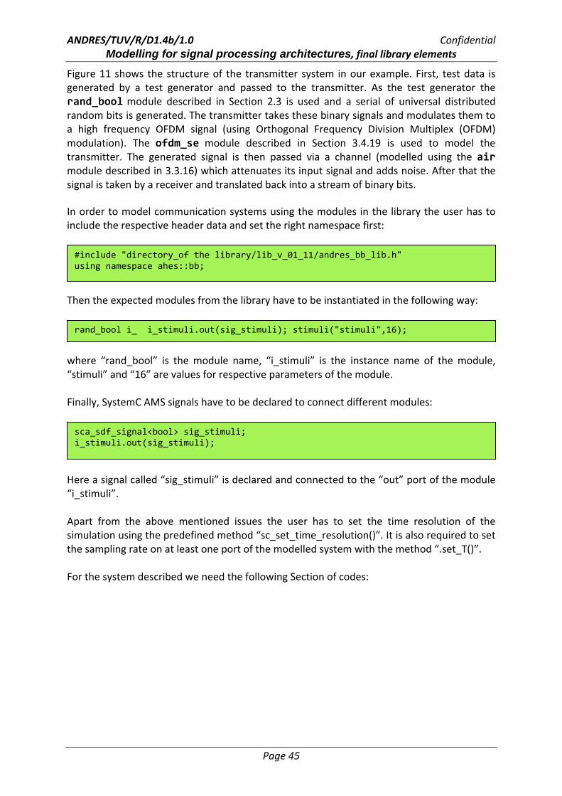
5 Example: OFDM Transmitter system The purpose of this chapter is to show the user how to use the modules from this building block library to model communication systems. We assume that the user who uses this library already has some basic knowledge of SystemC AMS. Based on the previously described modules an OFDM transmitter system is built up (see Figure 11) in this Section.
Figure 11 Top level block diagram of the example application
ANDRES/TUV/R/D1.4b/1.0 Confidential Modelling for signal processing architectures, final library elements
Page 45
Figure 11 shows the structure of the transmitter system in our example. First, test data is generated by a test generator and passed to the transmitter. As the test generator the rand_bool module described in Section 2.3 is used and a serial of universal distributed random bits is generated. The transmitter takes these binary signals and modulates them to a high frequency OFDM signal (using Orthogonal Frequency Division Multiplex (OFDM) modulation). The ofdm_se module described in Section 3.4.19 is used to model the transmitter. The generated signal is then passed via a channel (modelled using the air module described in 3.3.16) which attenuates its input signal and adds noise. After that the signal is taken by a receiver and translated back into a stream of binary bits. In order to model communication systems using the modules in the library the user has to include the respective header data and set the right namespace first:
Then the expected modules from the library have to be instantiated in the following way:
where “rand_bool” is the module name, “i_stimuli” is the instance name of the module, “stimuli” and “16” are values for respective parameters of the module. Finally, SystemC AMS signals have to be declared to connect different modules:
Here a signal called “sig_stimuli” is declared and connected to the “out” port of the module “i_stimuli”. Apart from the above mentioned issues the user has to set the time resolution of the simulation using the predefined method “sc_set_time_resolution()”. It is also required to set the sampling rate on at least one port of the modelled system with the method “.set_T()”. For the system described we need the following Section of codes:
sca_sdf_signal<bool> sig_stimuli; i_stimuli.out(sig_stimuli);
rand_bool i_ i_stimuli.out(sig_stimuli); stimuli("stimuli",16);
#include "directory_of the library/lib_v_01_11/andres_bb_lib.h" using namespace ahes::bb;

ANDRES/TUV/R/D1.4b/1.0 Confidential Modelling for signal processing architectures, final library elements
Page 46
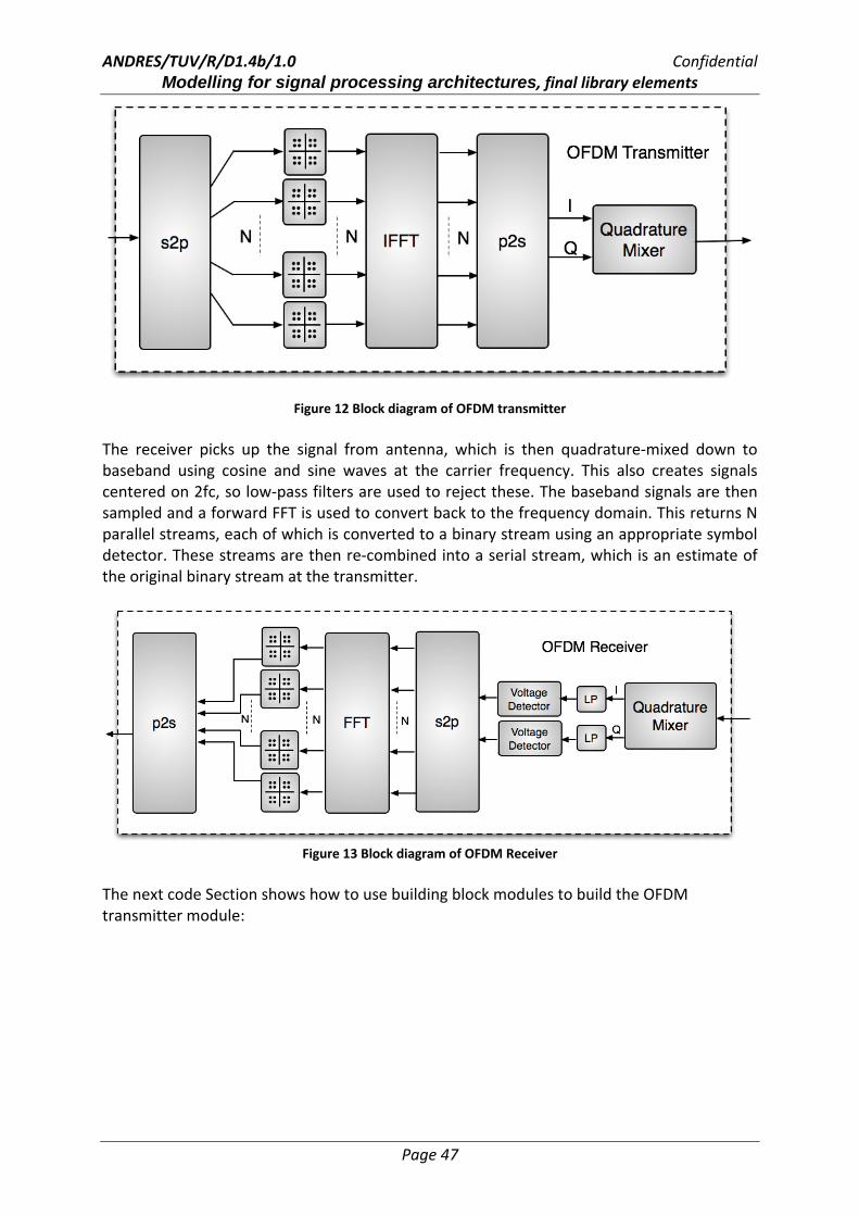
(This is not the complete source code) The transmitter and receiver modules consist again of sub modules, which are contained in the library. Figure 12 and Figure 13 present the internal structure of the transmitter module and receiver module, respectively. The transmitter takes a serial stream of binary digits. By inverse multiplexing, these are first demultiplexed into N parallel streams, and each one mapped to a (possibly complex) symbol stream using QAM modulation. An inverse FFT is computed on each set of symbols, giving a set of complex time‐domain samples. These samples are then quadrature‐mixed to passband in the standard way.
int sc_main(int argc, char* argv[]) { sc_set_time_resolution(1, SC_PS); // set the time resolution sca_sdf_signal<bool> sig_stimuli; // declare SystemC AMS signals sca_sdf_signal<double> sig_out; sca_sdf_signal<double> noise_out; ... rand_bool i_stimuli("stimuli",16); // instantiate test generator ofdm_se<8> i_tran("transmitter",constl_dim,freq_carrier,freq_bit,data_rate,
ampl_se); // instantiate transmitter air i_air("air",attent,"gauss_white",n_va,n_mean,data_rate); // instantiate channel ofdm_re<8> i_receiver("receiver",constl_dim,freq_carrier,freq_bit,data_rate,
1ampl_re); // instantiate receiver drain drn("drn"); // instantiate drain. This is only a
// module used to consume tokens as we // can not let a SystemC AMS scheduling // loop open.
i_stimuli.out.set_T(1/freq_bit,SC_SEC); //Time step has to be set to one of
the ports in the system i_stimuli.out(sig_stimuli); // connect different modules i_tran.in(sig_stimuli); i_tran.out(sig_out); ... sc_trace_file* wave = sc_create_vcd_trace_file("wave"); // VCD trace file: //With the VCD trace file, one can check if the received signal and stimuli //have identical values. sc_trace(wave, sig_stimuli ,"stimuli"); ... sc_start(0.05,SC_MS); // Simulation time: 0.05ms return 0; }
ANDRES/TUV/R/D1.4b/1.0 Confidential Modelling for signal processing architectures, final library elements
Page 47
Figure 12 Block diagram of OFDM transmitter The receiver picks up the signal from antenna, which is then quadrature‐mixed down to baseband using cosine and sine waves at the carrier frequency. This also creates signals centered on 2fc, so low‐pass filters are used to reject these. The baseband signals are then sampled and a forward FFT is used to convert back to the frequency domain. This returns N parallel streams, each of which is converted to a binary stream using an appropriate symbol detector. These streams are then re‐combined into a serial stream, which is an estimate of the original binary stream at the transmitter.
Figure 13 Block diagram of OFDM Receiver
The next code Section shows how to use building block modules to build the OFDM transmitter module:

ANDRES/TUV/R/D1.4b/1.0 Confidential Modelling for signal processing architectures, final library elements
Page 48
As we can see from the source code the modelling of an OFDM transmitter is quite easy when using the existing modules in the library. Simulation example:
template <int N> SC_MODULE(ofdm_se){
public: //Ports: sca_sdf_in<bool> in; // declare port sca_sdf_out<double> out; //signals sca_sdf_signal<bool> sig_pa[N]; //declare signals to connect sub modules sca_sdf_signal<double> sig_real[N]; ... private:
//module instantiation s2p<bool,N>* s2p_sub; qam_map* qam_mapper_sub[N]; fft_ifft<N>* ifft_sub; p2s<double,N>* p2s_r_sub; p2s<double,N>* p2s_i_sub; q_mixer_tr* q_mixer_tr_sub; public: //Constructor ofdm_se(sc_module_name n,int qam_p_num,double mixer_fc,double bit_f,int
dout_rate,double _amp=1) { int mixer_rate=(int)floor(dout_rate*log2(qam_p_num)*mixer_fc/bit_f); // instantiating modules and connecting them using signals s2p_sub = new s2p<bool,N>("s2p_sub",1); // serial to parallel module s2p_sub‐>in(in); for(int i=0;i<N;i++) s2p_sub‐>out[i](sig_pa[i]); ... ifft_sub = new fft_ifft<N>("ifft_sub","IFFT"); //IFFT module for(int i=0;i<N;i++) { ifft_sub‐>in_real[i](sig_real[i]); ifft_sub‐>in_imag[i](sig_imag[i]); ifft_sub‐>out_real[i](sig_out_real[i]); ifft_sub‐>out_imag[i](sig_out_imag[i]); } ... p2s_r_sub = new p2s<double,N>("p2s_r_sub",1); //quadrature mixer module
q_mixer_tr_sub = new q_mixer_tr("q_mixer_tr_sub",mixer_fc,_amp,0.,0.,mixer_rate,false);
q_mixer_tr_sub‐>i_in(sig_out_i); q_mixer_tr_sub‐>q_in(sig_out_q); q_mixer_tr_sub‐>out(out); /***/ } };
ANDRES/TUV/R/D1.4b/1.0 Confidential Modelling for signal processing architectures, final library elements
Page 49
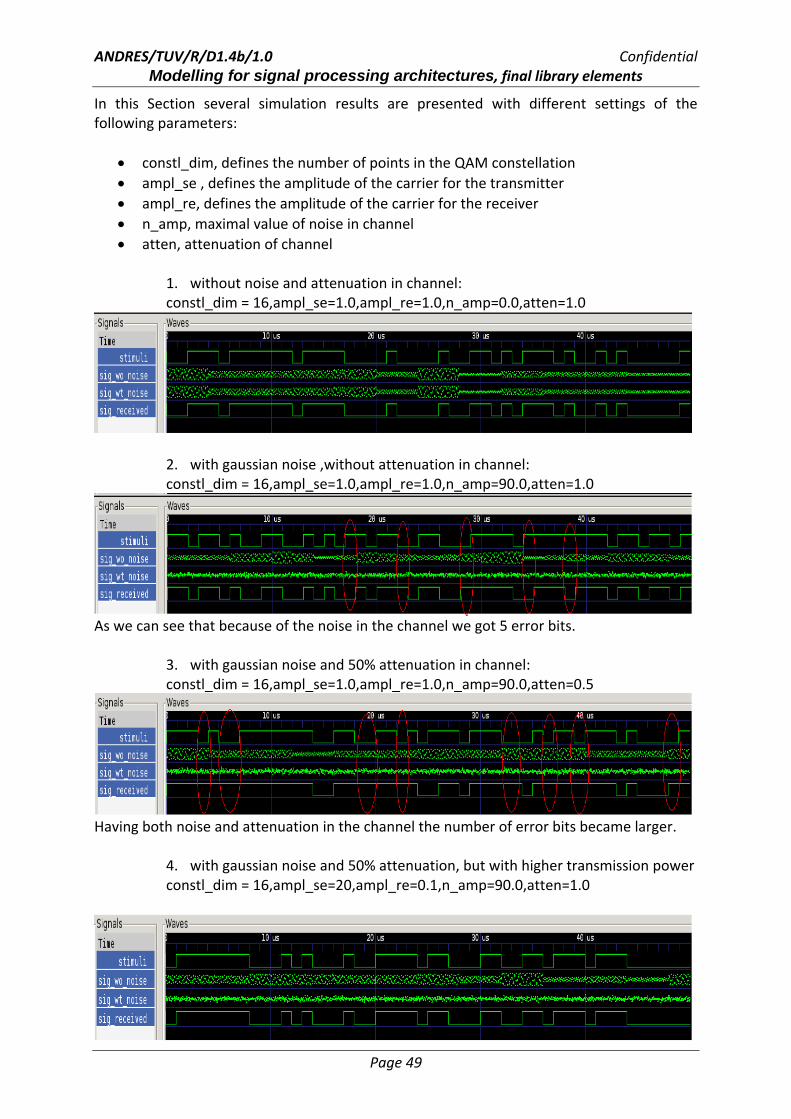
In this Section several simulation results are presented with different settings of the following parameters:
• constl_dim, defines the number of points in the QAM constellation • ampl_se , defines the amplitude of the carrier for the transmitter • ampl_re, defines the amplitude of the carrier for the receiver • n_amp, maximal value of noise in channel • atten, attenuation of channel
1. without noise and attenuation in channel: constl_dim = 16,ampl_se=1.0,ampl_re=1.0,n_amp=0.0,atten=1.0
2. with gaussian noise ,without attenuation in channel: constl_dim = 16,ampl_se=1.0,ampl_re=1.0,n_amp=90.0,atten=1.0
As we can see that because of the noise in the channel we got 5 error bits.
3. with gaussian noise and 50% attenuation in channel: constl_dim = 16,ampl_se=1.0,ampl_re=1.0,n_amp=90.0,atten=0.5
Having both noise and attenuation in the channel the number of error bits became larger.
4. with gaussian noise and 50% attenuation, but with higher transmission power constl_dim = 16,ampl_se=20,ampl_re=0.1,n_amp=90.0,atten=1.0

ANDRES/TUV/R/D1.4b/1.0 Confidential Modelling for signal processing architectures, final library elements
Page 50
As presented in this figure we can reproduce the correct signals with higher transmission power. This is due to the parameter “ampl_se” set to 20, which means the signal from the transmitter is 20 times as strong as by previous simulations.
5. with gaussian noise and 50% attenuation, but slowing down transmission speed
constl_dim = 4,ampl_se=1.0,ampl_re=1.0,n_amp=0.0,atten=1.0
Or it is also possible to slow down the transmission speed to improve the BER. This is due to the parameter “constl_dim” set to 4, which means now only 2 bits (which is 4 bits when setting “constl_dim” to 16) were encoded at one time.
6 Conclusion and future work The implementation of building blocks was successful. Up to now more than 60 modules are implemented which cover the most important building blocks of communication and high frequency systems: signal sources, basic signal processing modules and signal analysis units. All the modules are augmented with means for specification of adaptivity and re‐configurability by the parameterization of modules according to respective hardware features. Non‐ideal effects of analogue realizations are also implemented for some modules. In the future, more building blocks will be provided, e.g. commonly used encoders and decoders, channel modules with frequency dependency and more signal analysis units. Moreover abstract adaptive modules will be implemented to enhance the adaptivity and re‐configurability of the building block library.

ANDRES/TUV/R/D1.4b/1.0 Confidential Modelling for signal processing architectures, final library elements
Page 51
7 References [1] E.A.Lee and D.G.Messerschmitt. Digital Communication. Springer Netherlands, third edition 2004. [2] Behzad Razavi. RF Microelectronics . Prentice Hall PTR 1998. [3] U. Tietze and Ch.Schenk. Halbleiter‐Schaltungstechnik. Springer, 12. Auflage. [4] William H. Press, Brian P. Flannery, Saul A. Teukolsky , William T. Vetterling. Numerical Recipes in C: The Art of Scientific Computing. Cambridge University Press; 2 edition (October 30, 1992) [5] B. P. Lathi. Signal Processing and Linear Systems. Oxford University Press, USA (February 24, 2000) [6] F. Brame, J. Haase, C. Grimm, “Modelling of signal processing architectures, initial library elements”, ANDRES Deliverable D1.4a, 31.05.2007

ANDRES/TUV/R/D1.4b/1.0 Confidential Modelling for signal processing architectures, final library elements
Page 52
8 Appendix Here the complete source code from Section 5 is presented. main.cpp:
#include "systemc‐ams.h" #include "/home/ou/works/lib/lib_v_01_11/andres_bb_lib.cpp" using namespace ahes::bb; SCA_SDF_MODULE(drain) { sca_sdf_in<bool> in; SCA_CTOR(drain) {} }; int sc_main(int argc, char* argv[]) { sc_set_time_resolution(1, SC_PS); // setting the time resolution /* ********* defining signals and parameters *********** */ sca_sdf_signal<bool> sig_stimuli; sca_sdf_signal<double> sig_out; sca_sdf_signal<double> noise_out; sca_sdf_signal<double> sig_noise; sca_sdf_signal<bool> sig_received; int constl_dim; double ampl_se; double ampl_re; double n_va; double attent; /* ********* setting parameters for simulation *********** */ cout<<data_rate<<endl; cout<<"step ="<<1/freq_bit*8*2/data_rate<<endl; cout << "constel_dim = "; cin >> constl_dim; cout << "ampl_se = "; cin >> ampl_se; cout << "ampl_re = "; cin >> ampl_re; cout << "n_va = "; cin >> n_va; cout << "attent = "; cin >> attent; /* ********* instantiating SDF‐modules ********* */
rand_bool i_stimuli("stimuli",16); i_stimuli.out(sig_stimuli); i_stimuli.out.set_T(1/freq_bit,SC_SEC); ofdm_se<8> i_tran("transmitter",freq_carrier,constl_dim,freq_bit,data_rate, ampl_se); i_tran.in(sig_stimuli); i_tran.out(sig_out); air i_air("air",attent,"gauss_white",n_va,0,1); i_air.in(sig_out); i_air.out(sig_noise);
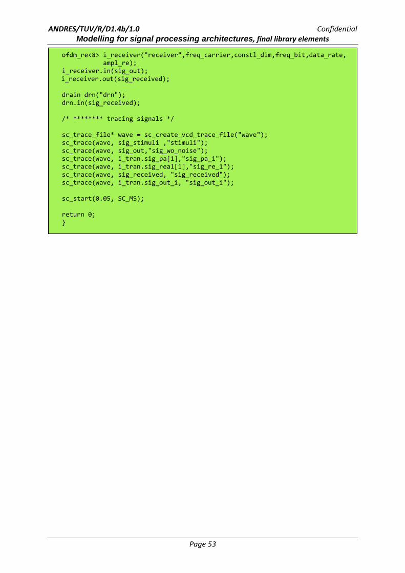
ANDRES/TUV/R/D1.4b/1.0 Confidential Modelling for signal processing architectures, final library elements
Page 53
ofdm_re<8> i_receiver("receiver",freq_carrier,constl_dim,freq_bit,data_rate, ampl_re); i_receiver.in(sig_out);
i_receiver.out(sig_received); drain drn("drn"); drn.in(sig_received); /* ******** tracing signals */ sc_trace_file* wave = sc_create_vcd_trace_file("wave"); sc_trace(wave, sig_stimuli ,"stimuli"); sc_trace(wave, sig_out,"sig_wo_noise"); sc_trace(wave, i_tran.sig_pa[1],"sig_pa_1"); sc_trace(wave, i_tran.sig_real[1],"sig_re_1"); sc_trace(wave, sig_received, "sig_received"); sc_trace(wave, i_tran.sig_out_i, "sig_out_i"); sc_start(0.05, SC_MS); return 0; }

ANDRES/TUV/R/D1.4b/1.0 Confidential Modelling for signal processing architectures, final library elements
Page 54
ofdm_se.h
template <int N> SC_MODULE(ofdm_se){ public: //Ports: sca_sdf_in<bool> in; // input port sca_sdf_out<double> out; // output port //signals sca_sdf_signal<bool> sig_pa[N]; //signals on s2p output ports sca_sdf_signal<double> sig_real[N]; //signals on q_mapper i output ports sca_sdf_signal<double> sig_imag[N]; //signals on q_mapper q output ports sca_sdf_signal<double> sig_out_real[N]; //signals on fft real output ports sca_sdf_signal<double> sig_out_imag[N]; //signals on fft imag output ports sca_sdf_signal<double> sig_out_i; //signals on p2s i output ports sca_sdf_signal<double> sig_out_q; //signals on p2s q output ports private: //module instantiation s2p<bool,N>* s2p_sub; qam_map* qam_mapper_sub[N]; fft_ifft<N>* ifft_sub; p2s<double,N>* p2s_r_sub; p2s<double,N>* p2s_i_sub; q_mixer_tr* q_mixer_tr_sub; public: //Constructor ofdm_se(sc_module_name n,double mixer_fc,int qam_p_num,double bit_f,int
dout_rate,double _amp=1,int s2p_or=1,bool mixer_config=false,int p2s_rate=1) { int mixer_rate=(int)floor(dout_rate*log2(qam_p_num)*mixer_fc/bit_f); s2p_sub = new s2p<bool,N>("s2p_sub",1); s2p_sub‐>in(in); for(int i=0;i<N;i++) s2p_sub‐>out[i](sig_pa[i]); for(int i=0;i<N;i++) { sc_module_name nm(((string)"qam_mapper_sub_"+(char)(i+65)).c_str()); qam_mapper_sub[i] = new qam_map(nm ,qam_p_num); qam_mapper_sub[i]‐>in(sig_pa[i]); qam_mapper_sub[i]‐>out_i(sig_real[i]); qam_mapper_sub[i]‐>out_q(sig_imag[i]); } ifft_sub = new fft_ifft<N>("ifft_sub","IFFT"); for(int i=0;i<N;i++) { ifft_sub‐>in_real[i](sig_real[i]); ifft_sub‐>in_imag[i](sig_imag[i]); ifft_sub‐>out_real[i](sig_out_real[i]); ifft_sub‐>out_imag[i](sig_out_imag[i]); }

ANDRES/TUV/R/D1.4b/1.0 Confidential Modelling for signal processing architectures, final library elements
Page 55
ifft_sub‐>out_imag[i](sig_out_imag[i]); } p2s_r_sub = new p2s<double,N>("p2s_r_sub",p2s_rate); for(int i=0;i<N;i++) { p2s_r_sub‐>in[i](sig_out_real[i]); } p2s_r_sub‐>out(sig_out_i); p2s_i_sub = new p2s<double,N>("p2s_i_sub",p2s_rate); for(int i=0;i<N;i++) { p2s_i_sub‐>in[i](sig_out_imag[i]); } p2s_i_sub‐>out(sig_out_q); q_mixer_tr_sub = new
q_mixer_tr("q_mixer_tr_sub",mixer_fc,_amp,mixer_rate,mixer_config,0.,0.); q_mixer_tr_sub‐>i_in(sig_out_i); q_mixer_tr_sub‐>q_in(sig_out_q); q_mixer_tr_sub‐>out(out); /***/ } };