Modelling friction stir welding: evolution of microstructure and weld geometry of aluminium alloy EN...
8
Modelling friction stir welding: evolution of microstructure and weld geometry of aluminium alloy EN AW 6061 M. Hossfeld (1) (1) Materials Testing Institute (MPA), University of Stuttgart 39 th MPA-Seminar October 8 and 9, 2013 in Stuttgart
-
Upload
hanspoffer -
Category
Documents
-
view
44 -
download
2
description
Friction stir welding (FSW) is a solid-state joining process mostly used to join aluminium alloys. FSW is well known for welds with excellent properties like very good static and fatigue strength, low distortion and almost plain surfaces. Properties of friction stir welded joints are the result of complex phenomena during the process like material flow and deposition, large material deformations and thermomechanical interactions. These determine the evolution of microstructure and weld geometry.Friction stir welded joints consist of four characteristic zones showing different microstructure and hence mechanical properties. The inner processing zone is strongly influenced both of the pin and the shoulder and is usually called stirring zone or Nugget. As a consequence of severe plastic deformation and heat input during FSW this zone is fully dynamically recrystallized. Thus the grains are refined up to diameters about 5-10μm resulting in a high-strength weld. Moreover, the Nugget is surrounded by a thermo-mechanical zone (TMAZ). The TMAZ is also subjected to remarkable plastic deformation and heat input. However, it is not stirred and not dynamically recrystallized. Nevertheless the microstructure is usually heavily distorted and the affected grains are elongated, particularly at the transition to the nugget zone. These elongated grains can reach lengths about 100μm and widths about 5μm. Furthermore, some recrystallization seeds can occasionally be found in the TMAZ. The TMAZ is enclosed by a heat affected zone (HAZ). Although this zone is not subjected to plastic deformation the microstructure of the weld may be altered by the process heat input. Depending on the given aluminium alloy and its original condition this may range from slight grain growth to accelerated age hardening.Due to these effects it is important to improve the knowledge about these complex phenomena in order to optimise the mechanical properties and the geometry of the welded joint. Since the actual process is hardly observable a numerical 3D model was developed for the whole FSW process within the FE code ABAQUS® V6.12. Thereby a better understanding of the process, its influences and their strong interactions among themselves should be enabled. In this study numerical results for temperature fields, weld formation and an approach for microstructure evolution are shown and compared to experimental investigations
Transcript of Modelling friction stir welding: evolution of microstructure and weld geometry of aluminium alloy EN...
Modelling friction stir welding: evolution of microstructure and weld geometry of aluminium alloy EN AW 6061
M. Hossfeld(1)
(1) Materials Testing Institute (MPA), University of Stuttgart
39th MPA-Seminar October 8 and 9, 2013 in Stuttgart
Abstract
Friction stir welding (FSW) is a solid-state joining process mostly used to join aluminium alloys. FSW is well known for welds with excellent properties like very good static and fatigue strength, low distortion and almost plain surfaces. Properties of friction stir welded joints are the result of complex phenomena during the process like material flow and deposition, large material deformations and thermomechanical interactions. These determine the evolution of microstructure and weld geometry.
Friction stir welded joints consist of four characteristic zones showing different microstructure and hence mechanical properties. The inner processing zone is strongly influenced both of the pin and the shoulder and is usually called stirring zone or Nugget. As a consequence of severe plastic deformation and heat input during FSW this zone is fully dynamically recrystallized. Thus the grains are refined up to diameters about 5-10μm resulting in a high-strength weld. Moreover, the Nugget is surrounded by a thermo-mechanical zone (TMAZ). The TMAZ is also subjected to remarkable plastic deformation and heat input. However, it is not stirred and not dynamically recrystallized. Nevertheless the microstructure is usually heavily distorted and the affected grains are elongated, particularly at the transition to the nugget zone. These elongated grains can reach lengths about 100µm and widths about 5µm. Furthermore, some recrystallization seeds can occasionally be found in the TMAZ. The TMAZ is enclosed by a heat affected zone (HAZ). Although this zone is not subjected to plastic deformation the microstructure of the weld may be altered by the process heat input. Depending on the given aluminium alloy and its original condition this may range from slight grain growth to accelerated age hardening.
Due to these effects it is important to improve the knowledge about these complex phenomena in order to optimise the mechanical properties and the geometry of the welded joint. Since the actual process is hardly observable a numerical 3D model was developed for the whole FSW process within the FE code ABAQUS® V6.12. Thereby a better understanding of the process, its influences and their strong interactions among themselves should be enabled. In this study numerical results for temperature fields, weld formation and an approach for microstructure evolution are shown and compared to experimental investigations.
1 Motivation
Friction stir welding (FSW) is a solid-state joining process mostly used to join aluminium alloys [1, 2]. FSW is well known for welds with excellent properties like very good static and fatigue strength, low distortion and almost plain surfaces [3, 4]. Properties of friction stir welded joints are the result of complex phenomena during the process like material flow and deposition, large material deformations and thermomechanical interactions. These determine the evolution of microstructure and weld geometry [5-7]. Due to this it is important to know about the complex process phenomena in order to optimise the mechanical properties and the geometry of the welded joint. Since the actual process with its strong interactions is hardly observable a numerical 3D model was developed for the whole FSW process within the FE code ABAQUS® V6.12 [8]. Thereby a better understanding of the process, its influences and their strong interactions among themselves should be enabled.
2 Friction Stir Welding Process
The basic operational principles of the FSW process are quite simple. However, the process implies complex interactions between material properties and flow, heat transport and process forces. The operational principles mainly consist of a combination of frictional
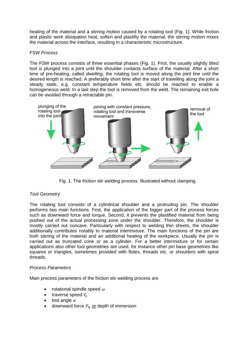
heating of the material and a stirring motion caused by a rotating tool (Fig. 1). While friction and plastic work dissipation heat, soften and plastifiy the material, the stirring motion mixes the material across the interface, resulting in a characteristic microstructure. FSW Process
The FSW process consists of three essential phases (Fig. 1). First, the usually slightly tilted tool is plunged into a joint until the shoulder contacts surface of the material. After a short time of pre-heating, called dwelling, the rotating tool is moved along the joint line until the desired length is reached. A preferably short time after the start of travelling along the joint a steady state, e.g. constant temperature fields etc. should be reached to enable a homogeneous weld. In a last step the tool is removed from the weld. The remaining exit hole can be avoided through a retractable pin.
Fig. 1. The friction stir welding process. Illustrated without clamping.
Tool Geometry The rotating tool consists of a cylindrical shoulder and a protruding pin. The shoulder performs two main functions. First, the application of the bigger part of the process forces such as downward force and torque. Second, it prevents the plastified material from being pushed out of the actual processing zone under the shoulder. Therefore, the shoulder is mostly carried out concave. Particularly with respect to welding thin sheets, the shoulder additionally contributes notably to material intermixture. The main functions of the pin are both stirring of the material and an additional heating of the workpiece. Usually the pin is carried out as truncated cone or as a cylinder. For a better intermixture or for certain applications also other tool geometries are used, for instance other pin base geometries like squares or triangles, sometimes provided with flutes, threads etc. or shoulders with spiral threads. Process Parameters Main process parameters of the friction stir welding process are
rotational spindle speed
traverse speed
tool angle
downward force or depth of immersion
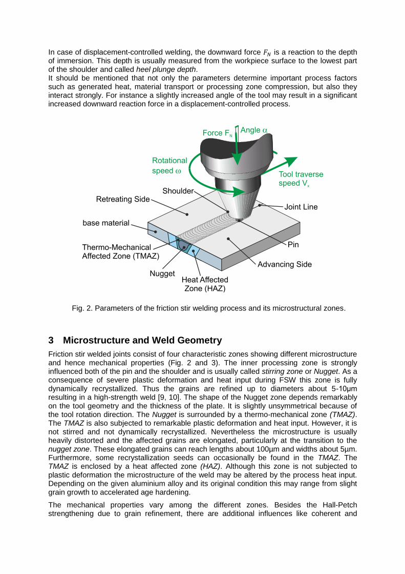
In case of displacement-controlled welding, the downward force is a reaction to the depth of immersion. This depth is usually measured from the workpiece surface to the lowest part of the shoulder and called heel plunge depth. It should be mentioned that not only the parameters determine important process factors such as generated heat, material transport or processing zone compression, but also they interact strongly. For instance a slightly increased angle of the tool may result in a significant increased downward reaction force in a displacement-controlled process.
Fig. 2. Parameters of the friction stir welding process and its microstructural zones.
3 Microstructure and Weld Geometry
Friction stir welded joints consist of four characteristic zones showing different microstructure and hence mechanical properties (Fig. 2 and 3). The inner processing zone is strongly influenced both of the pin and the shoulder and is usually called stirring zone or Nugget. As a consequence of severe plastic deformation and heat input during FSW this zone is fully dynamically recrystallized. Thus the grains are refined up to diameters about 5-10μm resulting in a high-strength weld [9, 10]. The shape of the Nugget zone depends remarkably on the tool geometry and the thickness of the plate. It is slightly unsymmetrical because of the tool rotation direction. The Nugget is surrounded by a thermo-mechanical zone (TMAZ). The TMAZ is also subjected to remarkable plastic deformation and heat input. However, it is not stirred and not dynamically recrystallized. Nevertheless the microstructure is usually heavily distorted and the affected grains are elongated, particularly at the transition to the nugget zone. These elongated grains can reach lengths about 100µm and widths about 5µm. Furthermore, some recrystallization seeds can occasionally be found in the TMAZ. The TMAZ is enclosed by a heat affected zone (HAZ). Although this zone is not subjected to plastic deformation the microstructure of the weld may be altered by the process heat input. Depending on the given aluminium alloy and its original condition this may range from slight grain growth to accelerated age hardening.
The mechanical properties vary among the different zones. Besides the Hall-Petch strengthening due to grain refinement, there are additional influences like coherent and
incoherent dispersoids, generation of dislocations, misorientation of grain angles etc. [11-13]. Moreover, crack paths predefined for instance by oxide particles or dispersoids have pronounced effect on fatigue life [3, 14]. Crack growth rates are strongly driven by the microstructure of the weld [15, 16].
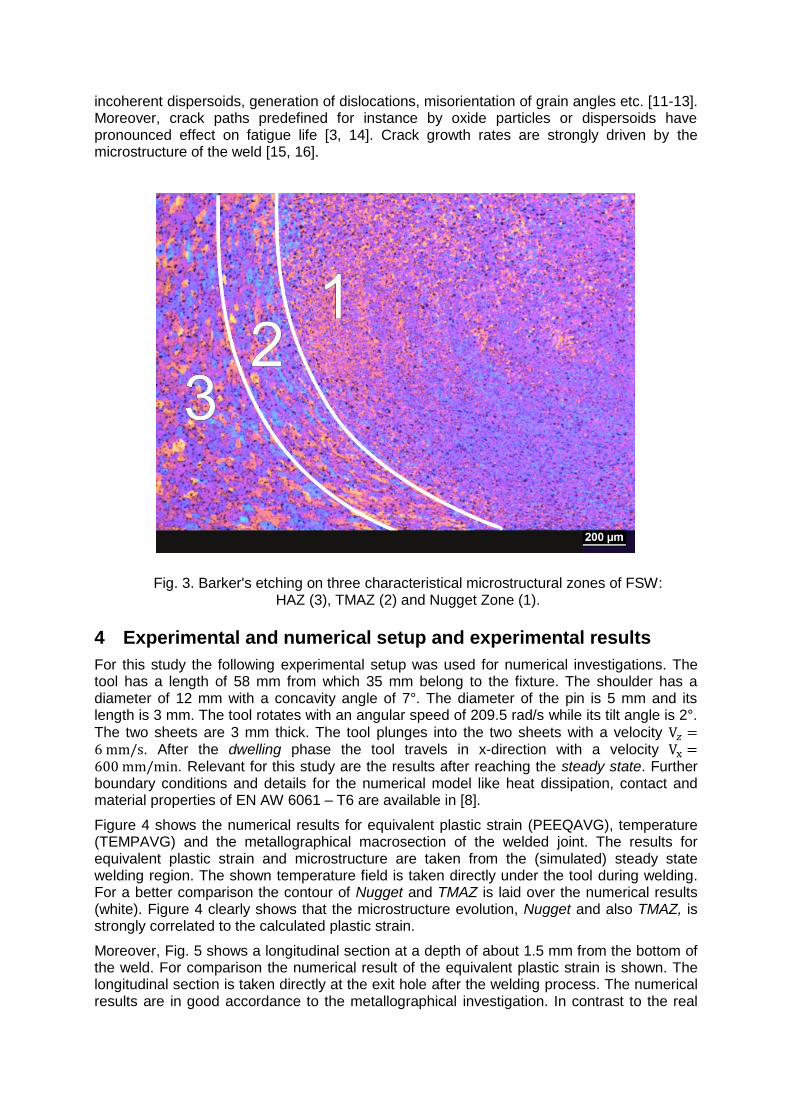
Fig. 3. Barker's etching on three characteristical microstructural zones of FSW: HAZ (3), TMAZ (2) and Nugget Zone (1).
4 Experimental and numerical setup and experimental results
For this study the following experimental setup was used for numerical investigations. The tool has a length of 58 mm from which 35 mm belong to the fixture. The shoulder has a diameter of 12 mm with a concavity angle of 7°. The diameter of the pin is 5 mm and its length is 3 mm. The tool rotates with an angular speed of 209.5 rad/s while its tilt angle is 2°.
The two sheets are 3 mm thick. The tool plunges into the two sheets with a velocity . After the dwelling phase the tool travels in x-direction with a velocity . Relevant for this study are the results after reaching the steady state. Further boundary conditions and details for the numerical model like heat dissipation, contact and material properties of EN AW 6061 – T6 are available in [8].
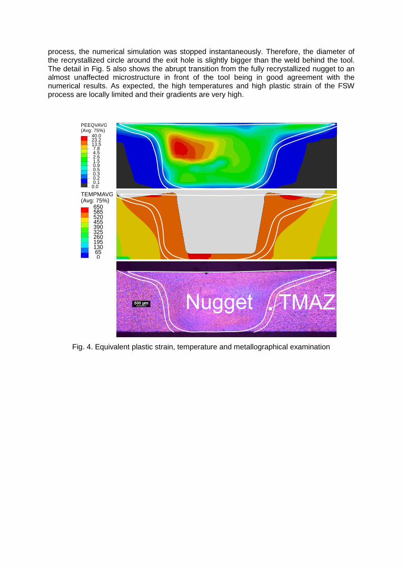
Figure 4 shows the numerical results for equivalent plastic strain (PEEQAVG), temperature (TEMPAVG) and the metallographical macrosection of the welded joint. The results for equivalent plastic strain and microstructure are taken from the (simulated) steady state welding region. The shown temperature field is taken directly under the tool during welding. For a better comparison the contour of Nugget and TMAZ is laid over the numerical results (white). Figure 4 clearly shows that the microstructure evolution, Nugget and also TMAZ, is strongly correlated to the calculated plastic strain.
Moreover, Fig. 5 shows a longitudinal section at a depth of about 1.5 mm from the bottom of the weld. For comparison the numerical result of the equivalent plastic strain is shown. The longitudinal section is taken directly at the exit hole after the welding process. The numerical results are in good accordance to the metallographical investigation. In contrast to the real
process, the numerical simulation was stopped instantaneously. Therefore, the diameter of the recrystallized circle around the exit hole is slightly bigger than the weld behind the tool. The detail in Fig. 5 also shows the abrupt transition from the fully recrystallized nugget to an almost unaffected microstructure in front of the tool being in good agreement with the numerical results. As expected, the high temperatures and high plastic strain of the FSW process are locally limited and their gradients are very high.
Fig. 4. Equivalent plastic strain, temperature and metallographical examination
(Avg: 75%)PEEQVAVG
0.1 0.2 0.3 0.5 0.9 1.5 2.6 4.5 7.813.523.240.0
0.0
(Avg: 75%)TEMPMAVG
0 65130195260325390455520
650

Fig. 5. Barker's etching, longitudinal section at 1.5mm from the bottom of the weld and numerical results for equivalent plastic strain
5 Summary and conclusion
In this study numerical results for temperature fields and weld formation are shown. These results are compared to metallographical examinations. The following conclusions can be drawn:
The results of the FE model regarding weld geometry and plastic strain are in good accordance with own experiments and their metallographical examinations.
Based on equivalent plastic strain and temperature field the microstructure evolution of FSW joints can be estimated.
The abrupt transition from nugget to base material can be found both in the metallographical examination and the numerical results.
Continuous dynamic recrystallization has to be taken into account separately for further research because of the high strain rates [17].
In a next step, the results shown in this study are used to investigate the strength and ductility of the joint and the occurring strain localization due to material inhomogeneities. This should be investigated by both tensile tests of real specimens with ARAMIS deformation analysis and virtual numerical tensile tests.
References
[1] W.M. Thomas, E.D. Nicholas, J.C. Needham, M.G. Murch, P. Temple-Smith, C.J. Dawes, “Friction-stir butt welding”, GB Patent No. 9125978.8, International patent application No. PCT/GB92/02203, 1991.
[2] C.J. Dawes, W.M. Thomas, “Friction stir joining of aluminium alloys”, TWI Bulletin 6, 1995.
[3] Institut für Materialprüfung, Werkstoffkunde und Festigkeitslehre (IMWF) Universität Stuttgart, “Mikrostrukturorientierte Analyse des Ermüdungs- und Schädigungsverhaltens von FSW-Schweißverbindungen sowie Lebensdauervorhersage betriebsbeanspruchter FSW-Bauteile unter Berücksichtigung korrosiver Effekte“, Forschungsvorhaben AiF-Nr. 15685 N/4, 2010.
[4] A. Scialpi, M. de Giorgi, L.A.C. de Filippis, R. Nobile, F.W. Panella, “Mechanical analysis of ultra-thin friction stir welding joined sheets with dissimilar and similar materials”, Materials & Design, Vol. 29, 2007, pp. 928–936.
[5] H.N.B. Schmidt, T.L. Dickerson, J.H. Hattel, “Material flow in butt friction stir welds in AA2024-T3”, Acta Materialia, Vol. 54, 2006, pp. 1199-1209.
[6] A.A.M. da Silva, E. Arruti, G. Janeiro, E. Aldanondo, P. Alvarez, A. Echeverria, “Material flow and mechanical behaviour of dissimilar AA2024-T3 and AA7075-T6 aluminium alloys friction stir welds”, Materials & Design, Vol. 32, 2011, pp. 2021-2027.
[7] M. Guerra, C. Schmidt, J.C. McClure, L.E. Murr, A.C. Nunes, “Flow patterns during friction stir welding”, Materials Characterization, Vol. 49, 2003, pp. 95-101.
[8] M. Hossfeld, E. Roos, “A new approach to modelling friction stir welding using the CEL method”, KTH Stockholm, Newtech, 2013.
[9] E.O. Hall, “The Deformation and Ageing of Mild Steel: III Discussion of Results”, Proceedings of the Physical Society London, Vol. 64, No. 381, 1951, pp. 747–753.
[10] N.J. Petch, “The Cleavage Strength of Polycrystals”, Journal of the Iron and Steel Institute, Vol. 174, 1953, pp. 25–28.
[11] F. Ostermann, “Anwendungstechnologie Aluminium,” Berlin: Springer, 2007
[12] ASM Handbook Volume 2: Properties and Selection: Nonferrous Alloys and Special-Purpose Materials, USA: ASM International, 1990.
[13] D. Altenpohl, “Aluminium und Aluminiumlegierungen,“ Reine und angewandte Metallkunde in Einzeldarstellungen, Vol.19, Berlin-Göttingen-Heidelberg-New York: Springer, 1965.
[14] M.N. James, D.G. Hattingh, G.R. Bradley, “Weld tool travel speed effects on fatigue life of friction stir welds in 5083 aluminium,” International Journal of Fatigue, Vol. 25, 2003, pp. 1389–1398.
[15] T.H. Tra, M. Okazaki, K. Suzuki, “Crack propagation microstructure Fatigue crack propagation behavior in friction stir welding of AA6063-T5: Roles of residual stress and microstructure”, International Journal of Fatigue, Vol. 43, October 2012, pp. 23–29.
[16] M. D. Sangid, “The physics of fatigue crack initiation”, International Journal of Fatigue, accepted/corrected proof, 2012.
[17] K.V. Jata, S.L. Semiatin, “Continuous dynamic recrystallization during friction stir welding of high strength aluminum alloys”, Scripta Materialia, Vol. 43, 2000, pp. 743-749