Modelling Concrete and Steel Projects using Autodesk...
48
Modelling Concrete and Steel Projects using Autodesk® Revit® Structure Graham H Stewart, Buro Happold, BIM Manager SE3520 This class is designed for structural engineering professionals with beginning or intermediate experience with Revit Structure. This class will cover a combination of best practices on how to model in Revit Structure, including project set up, using scope boxes and filters, various types of schedules, and general modelling principles. Attendees should have general Revit Structure knowledge Learning Objectives At the end of this class, you will be able to: • Learning objective 1 - The Basics • Learning objective 2 – Model Management • Learning objective 3 – Modeling Best Practices • Learning objective 4 - Schedules About the Speaker Graham – A BIM Manager who has over 20 year’s experience in the AEC industry (covering 10+ years using various 3D software packages including 5 years using Revit) specialising in BIM & Revit. Responsible for managing structural BIM development in Buro Happold’s Northern Europe Region, seen as a leader in BIM and part of many initiatives including the BIM XC and the Global BIM Committee. In 2009 Graham co-founded GRUG - The Glasgow Revit User Group which holds meetings with like-minded professionals within the industry covering Architecture, Structures, Building Services, Contractors & Education. Graham is also a Certified AutoDesk Revit Architecture 2011 Professional. Email: [email protected] Twitter: StewartGH1970 Blog: Revit5
Transcript of Modelling Concrete and Steel Projects using Autodesk...
Modelling Concrete and Steel Projects using Autodesk® Revit®
Structure Graham H Stewart, Buro Happold, BIM Manager
SE3520
This class is designed for structural engineering professionals with beginning or
intermediate experience with Revit Structure. This class will cover a combination of best
practices on how to model in Revit Structure, including project set up, using scope
boxes and filters, various types of schedules, and general modelling principles.
Attendees should have general Revit Structure knowledge
Learning Objectives
At the end of this class, you will be able to:
• Learning objective 1 - The Basics
• Learning objective 2 – Model Management
• Learning objective 3 – Modeling Best Practices
• Learning objective 4 - Schedules
About the Speaker
Graham – A BIM Manager who has over 20 year’s experience in the AEC industry (covering
10+ years using various 3D software packages including 5 years using Revit) specialising in
BIM & Revit.
Responsible for managing structural BIM development in Buro Happold’s Northern Europe
Region, seen as a leader in BIM and part of many initiatives including the BIM XC and the
Global BIM Committee.
In 2009 Graham co-founded GRUG - The Glasgow Revit User Group which holds meetings
with like-minded professionals within the industry covering Architecture, Structures, Building
Services, Contractors & Education.
Graham is also a Certified AutoDesk Revit Architecture 2011 Professional.
Email: [email protected]
Twitter: StewartGH1970 Blog: Revit5
SE3520 Modelling Concrete and Steel Projects using Autodesk® Revit® Structure
Contents The Basic’s ............................................................................................................................. 3
Do ....................................................................................................................................... 3
Do Not ................................................................................................................................ 4
Interface ............................................................................................................................. 5
Revit Co-Ordination .......................................................................................................... 7
Model Management ................................................................................................................ 8
Modelling ........................................................................................................................... 9
Grid Lines .........................................................................................................................13
Levels ...............................................................................................................................14
Scope Boxes ....................................................................................................................15
Views ................................................................................................................................20
Annotation ........................................................................................................................21
Tags ..................................................................................................................................21
Worksets ..........................................................................................................................22
Worksharing .....................................................................................................................23
Project Bluestreak ...........................................................................................................24
File Maintenance On Projects .........................................................................................25
Sending Out A Revit File For Coordination ....................................................................26
Collaboration ....................................................................................................................27
Filters ................................................................................................................................28
Creating Selection Sets ...................................................................................................30
Modelling Best Practices .......................................................................................................34
Concrete ...........................................................................................................................34
Steel ..................................................................................................................................35
Walls .................................................................................................................................36
Floors ................................................................................................................................37
Beams ...............................................................................................................................37
Schedules .............................................................................................................................38
Excel Table Links To Autocad ........................................................................................38
Creating Schedules using Type Catalogs ......................................................................43

SE3520 Modelling Concrete and Steel Projects using Autodesk® Revit® Structure
The Basic’s
Do
• Always model accurately and reliably
• Only model what you're responsible for i.e. don't model other disciplines (unless agreed
upon in BIM Kickoff Meeting, i.e. - slabs.)
• Model as much as possible within reason and to your level of experience
• If you don’t know ask – never assume, search the AUGI/Autodesk discussion Forums
and ask your local Office BIM Champion
• If you are carrying out a task and it is taking a long time ask if it can be done quicker
• Make sure Press + Drag is un-ticked on the options bar to avoid moving elements by
mistake
• Before revising levels check framing & column schedules to make sure any associated
elements won’t be affected.
• Model everything at a reference level that you want independent parametric control over.
If elements are modeled with an associative vertical offset, parametric control is only
achieved by modifying the host object.
• Try to keep all of your project drawn in revit. If circumstances mean you can't for
whatever reason, then make sure all of your external details are referenced into revit
(linked) and placed on revit sheets.
• Have a clear division of work - vital for multi-user projects.
• Always draw elements in a consistent direction:
• Either top to bottom or bottom to top
• Either left to right or right to left
This will help with analytical properties to ensure you know which is end 1 and end 2 –
although this can be verified by switching on Analytical Model Visibility.

SE3520 Modelling Concrete and Steel Projects using Autodesk® Revit® Structure
Do Not
• Under no circumstance should Beta versions of Revit be used for Live projects
• Revit is a parametric modeling system and cannot be fudged!
• Model to suit to your level of experience – no point spending hours trying to model
something in 3d when you could have spent 10mins on a 2 detail – this is dependent on
the level of coordination you will be performing
• Never over model – no point making the model look pretty if you are only producing
drawings at a high scale – higher levels of modeling can be added at a later date if
required and to suit your agreed level of coordination in accordance with the BIM
Execution Plan, AIA/AIACC IPD Guide, AIAE202, AEC (UK) BIM Standards etc
• Jump straight into modeling – always plan ie BIM kick off meeting.

SE3520 Modelling Concrete and Steel Projects using Autodesk® Revit® Structure
Interface
The Browser
View, User Interface, Browser Organisation, this
allows you to change how the project browser is
organised.

SE3520 Modelling Concrete and Steel Projects using Autodesk® Revit® Structure
Quick Access Toolbar:
This allows you to add your favorite and most commonly used buttons to always be visible so
you don’t have to go through the tabs to find them.

SE3520 Modelling Concrete and Steel Projects using Autodesk® Revit® Structure
Revit Co-Ordination
Hold a Revit/BIM Start-Up meeting at the beginning of the project to discuss the following:
1. BIM Contact in each office
2. Understand and communicate the level of detail in the model you are trying to achieve at
any given stage of a project.
3. Co-ordinate your design wherever possible e.g. Zone numbering, Building numbering,
Core numbering, even door/void numbering on large jobs – see Filters
4. Confirm all software being used in the project and what version and build (Note: This
should not change during the project lifecycle unless ALL members of the design team
agree)
5. Specific Project/Client standards ie File naming, Worksets, Project Origin
• Are there project standards?
• BIM/Revit standards used by each consultant, view/workset naming
• Filenames to remain the same throughout the job
• How is the project/models being broken up?
• If a single floor fills more than 1 sheet, architect to provide matchlines.
• Recommended workset no bigger than: 10 floors in a tower, one quad in a sports
facility or roughly no more than 250,000 sf/25,000 m2 per model.
• MEP breaks by discipline and size
6. Project Units (if metric, mm, If Imperial, 1'-0")
7. Control of Grids and Levels / Copy Monitor
• Who is going to control the grids and levels for the project?
• T.O. Finish Floor vs. T.O Structural. Slab.
• Will copy/monitor be used? If yes, have all team members refrain from deleting
elements and recreating them if at all possible.
8. Any special sheet requirements?
• Get the Architect's border family/file, size of sheet (A0, 36x48, etc.)
• Sheet numbering convention
• Any special sheet requirements?
9. Special Job Requirements?
• DWG, DWF Exports
• Layer Conventions - Standards Checker in AutoCAD?
10. Agree how regularly you exchange your models and how ie email, FTP etc.using
eTransmit from AutoDesk Labs
11. Clash Detection
• In Revit?
• Navisworks?

SE3520 Modelling Concrete and Steel Projects using Autodesk® Revit® Structure
Model Management
• Minimize view depth, if possible, in elevation, plan, and section views. In addition, use
section boxes when working in 3D views.
• Groups are heavier than families. You can use an array to copy and associate objects
together. However, after the array is complete, you can ungroup the arrayed objects to
increase performance by removing the parametric associations of the copied objects.
(Note: Only do this if you are sure the group won't change again) You can also clear the
Copy and Associate check box when creating the array.
• Close any unnecessary windows. When working in a 3D view, most of the file is placed
into RAM. It is also strongly recommended that you close these views when saving to a
central file, because these views are regenerated as part of the process.
• Turn off shadows in most views. (Turn off shadows when printing views if not absolutely
necessary.)
• When making significant changes to a project (for example, moving a level or making
major geometry changes) it is strongly recommended that you perform these operations
when no other users are working on the file and they have relinquished all elements.
Then have user make new local files.
• Delete unused 3D views from sheet / views
• Do not store any rendering views these should be saved as jpg’s – it is recommended
that you only store the original 3D views for further renderings
Note: These views should be placed under the renderings section of the project browser.
They should also be saved by right clicking on the little house in the top right hand
corner of the screen and selecting 'save view'. Moreover, Revit 2012 will allow you to
physically lock the view.

SE3520 Modelling Concrete and Steel Projects using Autodesk® Revit® Structure
Modelling
Project North/True North:
Your building should be modeled in revit from start off as you would want it to appear on paper
i.e. horizontal/square to the screen (Project North). It should be positioned in relation to the
origin (see below). You'll also need the correct World Co-ordinate System setup (or True North),
obtained from a geographical/site survey or relevant drawing. There are a couple of different
ways to do this within your project.
1. Setup an external revit (site) file in which you set up world co-ordinates and then publish
the position back to your building model.
2. Specific coordinates at know points in the model
Project Origin & Location:
The revit origin is marked on plan by the project origin base point Note: If this is not visible
please to go VV then Site and tick Project Origin. It is from this intersection point that revit
performs its internal calculations and it is important that when modeling one considers this and
models as close to the origin point as possible to prevent problems with display and operations.
As a standard you should therefore:
• Model all circular/elliptical/symmetrical buildings with their centre positioned on the origin
point. All sports grounds should be modeled with the center of the pitch on the origin
point.
• Model all rectilinear buildings with the bottom left grid intersection on the origin point.
The entire design team needs to agree this project positioning system wherever possible at the
beginning of a job. Where this position has been pre-defined by the architect we can either
adopt their positioning in relation to the origin (so long as it remains close i.e. <250metres) or
keep to the standard described above and move the Architect's revit model to suit.

SE3520 Modelling Concrete and Steel Projects using Autodesk® Revit® Structure
Linking 2d DWG Files:
When referencing 2d Autocad drawings in to your revit project one should try to link them to
'current view only' unless absolutely necessary (refer to Worksets for further guidance). If not
selected, the linked DWG will be visible in all other views including 3d views. Display errors
sometimes occur when linking DWG files and you might have come across 'jumping lines' when
selecting the DWG. Before linking, it is therefore advisable to copy and save the drawing in to a
folder to allow you to manipulate it without affecting the original.
Tidying Up AutoCAD Drawings for Import to Revit:
Note the following 3 options:
1. Run Audit, then bind in any X-Ref files, then explode the x-refs. You can then perform a
burst operation on all blocks and then purge and audit the entire file. Even paper-space
layouts can be deleted from the DWG if desired. If necessary perform a flatten operation
to eliminate rogue 3d lines. Check units in drawing (Note: check all layers of the DWG
file have been switched on and checked for lines, then return the layer state to original).
2. Or wblock out the entire drawing
3. Copy / paste into brand new drawing
Note: NEVER explode DWG's within the model as this will clutter Revit's object styles and Line-
Styles with data from the exploded imports. If you need to perform this then this operation
should be carried out within a new revit model so that all exploded elements can be converted
to revit elements and tidied up prior to inserting into your original model.

SE3520 Modelling Concrete and Steel Projects using Autodesk® Revit® Structure
Linked CAD Drawings – Visibility Setting Best Practice
Right mouse click on the linked drawing and select Override Graphics in View – By Element.
Set the whole thing to be Transparent and the Projection Line Weight to be 1. This turns off the
AutoCAD solid hatch as well as making the Revit model to be the dominant line. This is view
dependent so would need to be done every time a CAD drawing is linked.
CAD File linked in and brought to Foreground
CAD File – Override Graphic in View – By Element – Weight set to 1
SE3520 Modelling Concrete and Steel Projects using Autodesk® Revit® Structure
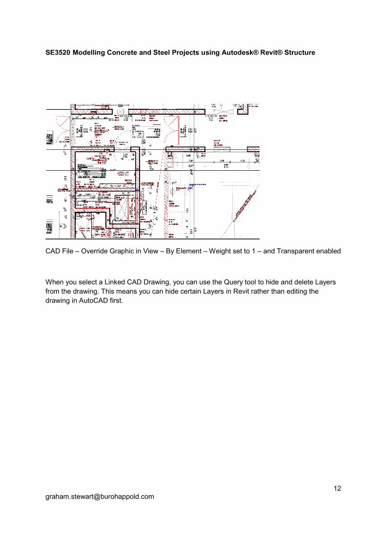
CAD File – Override Graphic in View – By Element – Weight set to 1 – and Transparent enabled
When you select a Linked CAD Drawing, you can use the Query tool to hide and delete Layers
from the drawing. This means you can hide certain Layers in Revit rather than editing the
drawing in AutoCAD first.

SE3520 Modelling Concrete and Steel Projects using Autodesk® Revit® Structure
Grid Lines
Propagate Extents – grids and Levels, allows you to set up how grids and Levels appear in one
view and then apply it to all views
Scope Boxes – Once grids have been created they should be assigned to a named scope box
Quick Tip: Set up a reference Grid Line which has no bubbles and is a different colour – this is
useful when you need to drawing centre lines for columns that are inline but not on a gridline.

SE3520 Modelling Concrete and Steel Projects using Autodesk® Revit® Structure
Levels
Scope Boxes – Once levels have been created they should be assigned to a names scope box
Quick Tip – How to list all levels in your current model
To get a snapshot of all the levels currently in your model use Revit Extensions – Grids
Generator and select Levels – as you can see from Figure 1.all levels are shown.
Figure 1

SE3520 Modelling Concrete and Steel Projects using Autodesk® Revit® Structure
Scope Boxes
Scope boxes perform functions as noted below:
Grids & Levels should be assigned to a name scope box to ensure uniformity of grid and level
extents between views. This works best for orthogonal/square buildings rather than round
buildings with radial grids because the scope box can only be cubic and radial grids won't
usually conform to this shape on plan.
Views – Scope boxes can also be used to align views at specific angles without the need to
rotate views on title sheets – this can be useful if you have a project where you have various
angled areas you wish to show orthogonal on plan.
Quick Tip: How to remember the rotation of scope boxes?
As a scope box does not remember its rotation angle set up ref lines to show the angle the
scope box has been rotated.

SE3520 Modelling Concrete and Steel Projects using Autodesk® Revit® Structure
Cast Study 1:
Problem:
Project had 5 unique areas at different orientations with 5 surround towers all at different levels.
Surrounding towers had to show floors plus levels
Main model had to be split up to show each area orthogonal on drawing sheets.

SE3520 Modelling Concrete and Steel Projects using Autodesk® Revit® Structure
Solution:
• Each area had a unique scope
box with all grids and levels assigned
• Dependant views where set up
each one assigned to a different scope
box

SE3520 Modelling Concrete and Steel Projects using Autodesk® Revit® Structure
Cast Study 2:
Problem
Exact same building from ground floor up to appear on 2 different sites at different levels and
different orientations.
SE3520 Modelling Concrete and Steel Projects using Autodesk® Revit® Structure
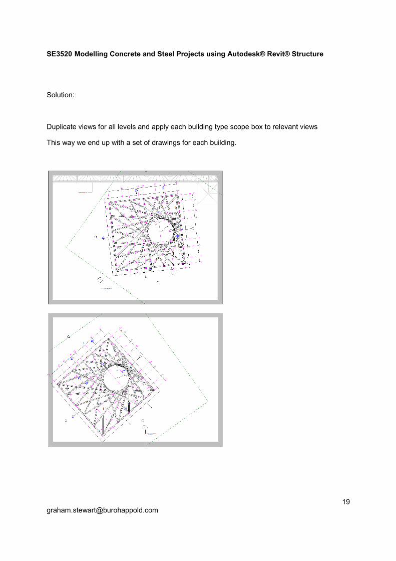
Solution:
Duplicate views for all levels and apply each building type scope box to relevant views
This way we end up with a set of drawings for each building.

SE3520 Modelling Concrete and Steel Projects using Autodesk® Revit® Structure
Views
Match Lines – used when views are split (as dependants). In the overall view, view, match lines,
draw a line where you want to split the drawing, click finish. Then view reference, select either
side of the match line. Edit the family, change the text to whatever you want. Create dependent
views for the split, and crop them to suit the area.
Quick Tip: Once one view is set up with dependent views, right mouse click on the original view
and choose apply dependent view and select which Levels you want the dependent views
copied too.
Quick Tip: View Discipline of unwanted sections
A quick way to keep unassociated sections off the drawings ie engineers review sections, is to
make their Discipline Architectural this way they only show up on your coordination review
plans.
Another way is to set up filters to specific sections types then apply these to specific view
templates

SE3520 Modelling Concrete and Steel Projects using Autodesk® Revit® Structure
Annotation
Windows commands that are useful for annotating
(Note: The following codes are for Arial Narrow)
© alt + 0169
« alt + 0171
® alt + 0174
° alt + 0176
± alt + 0177
² alt + 0178
³ alt + 0179
» alt + 0187
¼ alt + 0188
½ alt + 0189
¾ alt + 0190
ø alt + 0248
÷ alt + 0247
Quick Tip – Re-using text around the model
If are using typical notes that need to be applied at various locations in a view or multiple views
then Group text as this will allow all elements to updated in future.
Tags
If you need additional tags please edit one of the standard OOTB tags and amend to suit then
save to the \Revit\Family folder
Also insert shared parameters into Tags if you wish these to be schedules

SE3520 Modelling Concrete and Steel Projects using Autodesk® Revit® Structure
Worksets
All central files should start with the standard 2 worksets, Shared Levels and Grids and
Workset1.
Note: Workset1 should never be deleted or renamed as this could corrupt the model or cause
problems later on.
The following worksets should then be added as standard:
• 2D DWG – This workset is to be used when linking all DWG files – this will only
working in files are imported as 3d ie without Current View only ticked
• Revit Links – This workset is to be used when linking all Revit files
• Materials – This is a quick way to work in specific construction types and also for
easy of filtering by material type. Note: This can also be achieved by filters
Note: The above 2D DWG & Revit Links worksets are important in case you have corrupt files –
separating DWG/Revit links means you can specifically load the core model only.
For the 2D DWG workset to be effective you need to link in 2D CAD files without ‘Current view
only’ ticked. If you link in any CAD files with this ticked if will not have any effect even if you
unopen the above workset all 2D CAD files will still be visible and can only be unloaded via
Manage Links.
Note 1: These workset are for each linked 2D CAD or Revit file.
Note 2: For greater flexibility these worksets should switch off in all views so they you control
which views see 2d content or linked files (there are exceptions to this rule ie the linked file is
integral part of the model and needs to be seen)
Additional worksets should only be added to suit zoning, movement joints, divided up to suit
project resources or as per the linked models worksets for overall central control.
Note: It is not advisable to create worksets for separate elements i.e. columns, beams, walls etc
as you will get error notifications on joining elements when worksets are not editable. A workset
is not a layer manager, it is a modeling performance tool. Exceptions to this rule are when you
need to keep control over a whole set of elements that would otherwise be associated to
different worksets, e.g. masses of piles spreading over division zones.

SE3520 Modelling Concrete and Steel Projects using Autodesk® Revit® Structure
Worksharing
Please ensure you have the relevant Worksharing Monitor installed and running at all times
when accessing local or central files. Please use the following settings:
Note:
• If your name shows up RED then you are in the central file.
• If a Users name shows up GREY then they currently do not have Workshare monitor
loaded
Note: If you are using Revit Server you will not be able to use workshare monitor – please refer
to Project Bluestreak Section

SE3520 Modelling Concrete and Steel Projects using Autodesk® Revit® Structure
Project Bluestreak
The Blurb from Autodesk:
Project Bluestreak is the first collaboration solution to integrate informal project team
communication and automated notifications from AEC applications, starting with Revit. By
combining team communication tools with Revit worksharing notices and one-click file access in
a compact desktop app, Project Bluestreak consolidates multiple tools for BIM processes,
making team modeling more efficient.
The practicality:
Bluesteak as described by Autodesk brings together members of the design team to a simple
social media setting. Still in its beta stage it has some way to go but the main benefits I see
(apart from Revit Server) is that this can be used with non-revit server projects and can be used
to keep track of all revit models outside the office with the iphone app.

SE3520 Modelling Concrete and Steel Projects using Autodesk® Revit® Structure
File Maintenance On Projects
File management tips that help with keeping the file size as small as possible and avoid errors.
• Because of the memory leaks that are within Revit you should completely close out of
Revit atleast once a day and restart the program.
• Every time you open the project you should be making a new local file. This helps keep
a consistent local file.
• If your models crashes perform the following steps (ensure everyone has sync’d with the
central file and closed down all local files):
1. Open up the recovery model and perform a sync to ensure everything has been saved
over.
2. Audit the central file
3. Create a new local file – Note: Ensure all members of the project create new local files.
Revit Files with single users
1. Create a new Central File every 3 months or at different stages of the project (eg. stage
CD, DD or at major milestones)
2. Audit the Central File every month
3. Compact the Central File every month
4. Create a new Local File every week
Revit Files with multiple users
1. Create a new Central File every 1 month or at different stages of the project (eg. Stage
CD, DD or at major milestones)
2. Audit the Central File week
3. Create a new Local File every day.
Note: When creating a new Local File always appendage the existing file so that backups are
kept, these can be deleted every week or every month depending on how often new Local Files
are created (see above)
Purge unused regularly but check what is being removed – Note: This should only be done by
the lead BIM Project Coordinator.

SE3520 Modelling Concrete and Steel Projects using Autodesk® Revit® Structure
Sending Out A Revit File For Coordination
Recommended workflow for issuing Revit models to 3rd parties.
• Open the central file making sure you select 'detach from central' and 'Audit'
• Purge any unwanted items to reduce size
• Open the Start/Save view and date model accordingly
• Maximise this view, select 'Close Hidden Windows'
• Select 'Save As' and name appropriately according to your companies Revit standards.
• Place in Folder and zip using correct naming conventions (YY/MM/DD) and upload to
relevant site.
or
• Alternatively close revit model down and use eTransmit from AutoDesk Labs to package
up this model along with any attached/linked files.
SE3520 Modelling Concrete and Steel Projects using Autodesk® Revit® Structure
Collaboration
• When working in Revit it is VERY important that all members of the design team RST,
RCA & RMEP all work to the same version of revit and more importantly the same built
where possible to avoid any unnecessary errors during collaboration.
• At NO point should any one member of the design team upgrade their version of revit
until every member of the design team has agreed to this and also discussed possible
outcomes and a timeframe for checking and validating the model during the upgrade
process. Note: In multi discipline projects it may be of more benefit for MEP to upgrade.
• The whole point of BIM is the ability to easily coordinate and collaborate which you
cannot do within the same platform (as it was designed to) if everyone is using various
versions.
• Please also note that revit is not backward compatible (unofficial api products do exist –
but beware) (its not AutoCAD).
• Also Note that if you are in a later version of revit say 2012 you can link in a 2011 or
earlier versions of revit - this will perform an on the fly upgrade for that session only and
will not effect the original revit version. Again this is not recommended as you will lose
alot of time having to upgrade the project everytime you open revit.

SE3520 Modelling Concrete and Steel Projects using Autodesk® Revit® Structure
Filters
Every element is Revit should be part of a filter set to ensure schedules can work effectively and
drawings can be easily altered.
Note the following Filters that I use on projects (These filters where added using Shared
Parameters) to ALL categories in the template.
_Filter Comment 01 - Level information -- i.e. U3-U2, 01-03 or B, GF etc
_Filter Comment 02 - Category – This is used to separate framing members between
BRACING and TRUSS
_Filter Comment 03 - Host-Ref – This is used to state any host Ref ie for Door and Windows
you would enter the host wall ref or for Truss the Truss Ref
_Filter Comment 04 - Phase Filter
_Filter Comment 05 - Phase Filter – The 3 groups are used to build filter groups for phases
_Filter Comment 06 - Phase Filter
_Filter Comment 07 - View Filter – This group is use to amend the view ie turn elements off,
change the color or lineweights etc
_Filter Comment 08 - Comments – Add any comments of useful information for others to note
_Filter Comment 09 - Review Check – Add Eng Initials once Checked/Reviewed
_Filter Comment 10 - Design Ref – This is the ref from the Calcs, Analysis program
Note: Filter Comments 04-06 will not be covered in the class.
SE3520 Modelling Concrete and Steel Projects using Autodesk® Revit® Structure
Filter naming protocol:
Level – V or H ie U3-U2 V, U3 H
• All vertical elements should fall into U3-U2 V
• All horizontal elements should fall into U3 H
Quick Tip: Searching for elements that do or do not contain any information in a Filter field.
Filter by - contains –and leave blank - will leave on everything that has nothing in that filter
Filter by - does not contain – and leave blank will leave everything on that has something in the
filter

SE3520 Modelling Concrete and Steel Projects using Autodesk® Revit® Structure
Creating Selection Sets
Another way of using filters is the ability to create selection sets which in turn can show up in
filters.
By using this method you can quickly set up filters without having to go through all the normal
rules.
Quick Tip: For all saved section sets please prefix with SS-
Note: When you create a saved selection set this also appears in the filter list (Important – you
cannot edit this filter and if you select this filter and click edit you will be unable to create or edit
any filter) Please ensure you have set up a filter prior to creating saved selection sets.
Example: This example shows a wall loading plan (Figure 2) where selection sets have been set
up to identify different walls loadings as different colours.
Filters have been used to change the colour of the selection sets (Figure 4)
To Create a Selection Set: Pick an element(s) then in Manage (Figure 3) pick save (please
prefix with SS-)
To Edit a Selection Set: In Manage (Figure 3) pick Edit, then select the required prefixed SS-
selection set (Figure 5) then pick Edit – then use Add to/Remove from Section (Figure 6) to
make amendments
Filter Case Study:
The Problem: (Figure 7)
To create a 3D view that highlights all walls in the model that have the incorrect naming. As all
walls are named 2??-level-W(unique reference) we are looking for walls that do not start with 2.
Solution: (Figure 8)
Create a filter which looks at wall categories only and filters by Mark that does not being with 2.
This Filter is then used to surface shade walls soild RED.
Note: 2 No additional filters have been added to show all walls that do being with 2 and are
made transparent and switch all elements off except walls.

SE3520 Modelling Concrete and Steel Projects using Autodesk® Revit® Structure
Figure 2

SE3520 Modelling Concrete and Steel Projects using Autodesk® Revit® Structure
Figure 3
Figure 4
Figure 5
Figure 6

Figure 7
Figure 8

SE3520 Modelling Concrete and Steel Projects using Autodesk® Revit® Structure
Modelling Best Practices
Concrete
• All concrete columns should be modeled floor to floor, enabling them to scheduled
individually for rebar content
• All walls should be modeled floor to floor, enabling them to schedule individually for
rebar content (Note: For early scheme designs walls can be modeled full height then
split at a later date – Although this is not recommended as you will lose any associated
filters and parameters)
• For all voids to walls the structural opening families from the architectural menu ie doors
or windows should be used which can also be scheduled.
• You can't tag slab edges (also no analytical properties) therefore it's best to use a beam
for slab edge thickenings that need to be scheduled.
• When modifying a floor you'll often get the message - "Would you like walls that go up to
this floor's level to attach to its bottom?" - Say No as you should be in control on which
walls are attached to the floor not the computer
• If applying a concrete surface shading make sure you print your drawings using raster
processing as all annotation elements and transparent fill boundaries appear above the
surface shade.
• Use filters in your views for the above shading of elements rather than the overall
concrete surface shade which won't shade the ends of slabs, concrete stairs, and tops
and sides of walls. Applying surface shading with filters overcomes this problem.
• Beams should be modeled column to column except cantilevers.

SE3520 Modelling Concrete and Steel Projects using Autodesk® Revit® Structure
Steel
• All steelwork views to be set to Detail Level: Medium (UK Standard) - US Course
• All steel columns should be modeled full height and split once splice locations have been
verified by the contractor/fabricator – Note: Although this is should be agreed ASAP as
you will lose any associated filters and parameters.
• All steel framing members should be modeled at ref level ie Top Of Steel
• Steel framing should not be set down from top of slab level
• Make sure you select the appropriate structural usage from the element properties (i.e.
primary, secondary, tertiary), especially if you are drawing in course view - this will
ensure the correct weights for the members

SE3520 Modelling Concrete and Steel Projects using Autodesk® Revit® Structure
Walls
Modeling Walls:
• All External Walls should be shown modeled level to level with no offset
• All internal walls should be modeled floor to floor attach to slabs
Note: Analytical lines need to be reset to floor level if they are attached to floors
Editing Walls:
Drag Walls together to combine them adopts the properties of the Wall you are joining onto.
Structural Openings:
Openings through Walls, should be modeled using structural doors and window families as this
workflow allows quicker placement, editing opening sizes through duplication of families and all
information can be viewed in schedules which can also be used to quickly edit..

SE3520 Modelling Concrete and Steel Projects using Autodesk® Revit® Structure
Floors
All Slabs should be shown to the inside face of a Wall, except at the lowest Levels where the
Slab should go to the outside face of the Wall
Shafts for Cores should be taken to the inside of the core Walls.
Beams
Select member, right click and Detach from Plane, allows you to move it more freely or change
associated plane completely in element properties.

SE3520 Modelling Concrete and Steel Projects using Autodesk® Revit® Structure
Schedules
Excel Table Links To Autocad
A 2 way-link to updating schedules in Revit
This is a “how to“ for creating a link between an excel table and an AutoCAD table. This link
allows the excel table to be amended, and the link in AutoCAD can be reloaded and all the
changes will come through to the AutoCAD drawing.
1. Open Excel
2. Create the table in excel. No need to format the cells with a border, only if you want a
coloured background to them. Make sure the font in excel is the font you want the table
to be in on your drawing. Save somewhere sensible.
3. Open AutoCAD
4. Under the “Home” tab, choose Table from the “Annotation” panel, and the new dialog
box Opens.
5. Change the “Insert options” from “start from empty table” to “From a data link” and click
on this button.

SE3520 Modelling Concrete and Steel Projects using Autodesk® Revit® Structure
6. This brings up another dialog box called “Select a Data Link” Click on the “Create a new
Excel Data Link” and enter a sensible name for the link. eg. If it’s a Loading Diagram
Table then name it something similar to that.

SE3520 Modelling Concrete and Steel Projects using Autodesk® Revit® Structure
7. After you name it another dialog box opens called “New Excel Data Link: Followed by
the name you gave it.
Click on the a after the Browse for a file to
bring up explorer. Navigate through explorer
to find the Excel file that you saved in a
sensible location and click Open.

SE3520 Modelling Concrete and Steel Projects using Autodesk® Revit® Structure
8. The dialog box from step 7 is still open but it not contains “link options”
This is where you select which part of the excel spread sheet you want brought into drawing. If
the excel file only contains the information you want loaded in to the drawing then you can leave
it with “Link entire sheet” selected. Alternatively, you can change it to “Link to range:” This
allows you to choose which cells get copied, this has to be a continuous group of cells, and you
can’t ask it to miss out cells. NOTE: this can be altered after the table is loaded in if you want to
change it.
SE3520 Modelling Concrete and Steel Projects using Autodesk® Revit® Structure
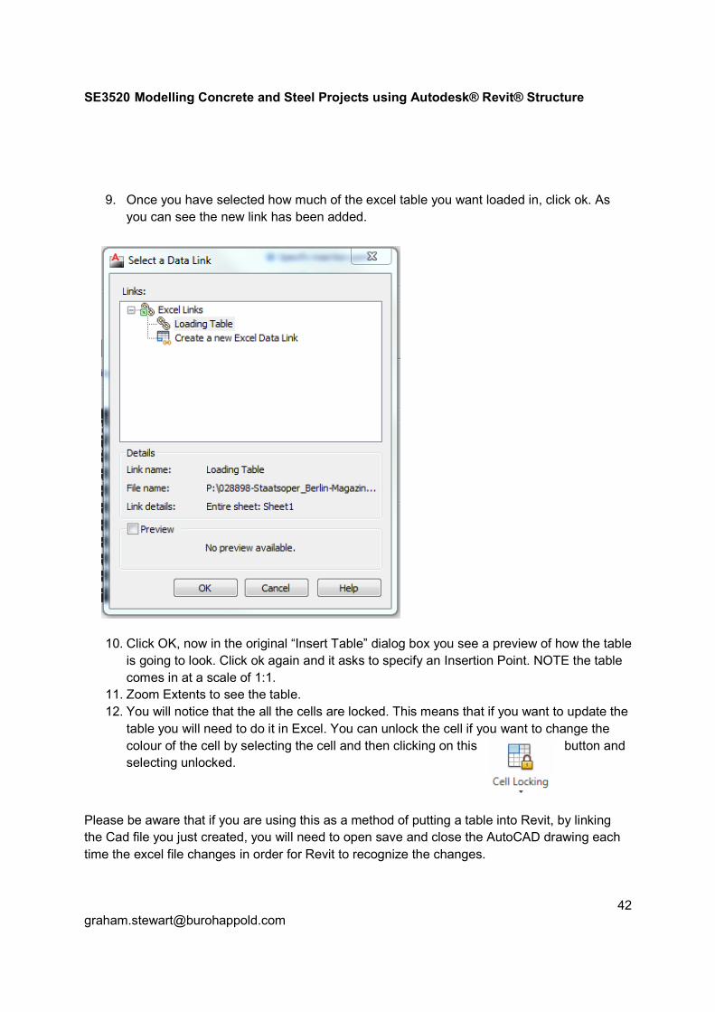
9. Once you have selected how much of the excel table you want loaded in, click ok. As
you can see the new link has been added.
10. Click OK, now in the original “Insert Table” dialog box you see a preview of how the table
is going to look. Click ok again and it asks to specify an Insertion Point. NOTE the table
comes in at a scale of 1:1.
11. Zoom Extents to see the table.
12. You will notice that the all the cells are locked. This means that if you want to update the
table you will need to do it in Excel. You can unlock the cell if you want to change the
colour of the cell by selecting the cell and then clicking on this button and
selecting unlocked.
Please be aware that if you are using this as a method of putting a table into Revit, by linking
the Cad file you just created, you will need to open save and close the AutoCAD drawing each
time the excel file changes in order for Revit to recognize the changes.

SE3520 Modelling Concrete and Steel Projects using Autodesk® Revit® Structure
Creating Schedules using Type Catalogs
Another method to create schedules within revit that can be updating using excel by creating
type catalogs.
Files: These have been included as additional class content and are also pre-loading in the
class project revit file
• Beam Schedule.xls
Typical Schedule
• Beam-Schedule-Body.rfa
Revit Family for schedule body
• Beam-Schedule-Body-txt
Text file renamed from csv export file from excel spreadsheet – Note: This filename must match
the schedule body filename exactly (except for file extension) and be located in same directory
as schedule body file
• Beam-Schedule-Header.rfa
Revit Family for schedule header
• REINFORCED CONCRETE BEAM SCHEDULE-CHECK.rvt
Revit Family Schedule for check all revit framing elements with -BM- in the mark

SE3520 Modelling Concrete and Steel Projects using Autodesk® Revit® Structure
The Process:
Excel
1. Engineer to filling in Beam Schedule.xls with all appropriate design values 2. Tech/Eng to take point 1 spreadsheet and in csv export worksheet – SaveAs CSV
comma delimited file 3. Point 2 *.csv file to be renamed to *.txt file – Note: This filename must match the
schedule body filename exactly (except for file extension) and be located in same directory as schedule body file
Revit
4. Insert Beam-Schedule-Header.rfa file using Insert -> Load Family 5. Go to beam schedule drawing and insert Beam-Schedule-Header using Annotate ->
Symbol – select from the pull down 6. Insert Beam-Schedule-Body file using Insert -> Load Family 7. Note: because point 3 *.txt file is located in the same directory you will now have a table
to select from – select ALL lines – Revit will now, using this information along with the Beam Schedule Body file, create a line for every level in your *.txt file
8. Insert Beam-Schedule-Body-?? (Note: ?? represents each line on the schedule which Revit has created) below the Beam Schedule Header using Annotation -> Symbol
9. After you have inserted each line your schedule is now complete. 10. When the engineer revises the schedule in the future follow points 2, 3 then point 7 –
from here select the whole table again and the schedule will be automatically updated in Revit – Note: If any new lines have been added simply follow point 8.
11. I have also included REINFORCED CONCRETE BEAM SCHEDULE-CHECK which can be inserted using Insert -> Insert from File -> Insert Views from File

SE3520 Modelling Concrete and Steel Projects using Autodesk® Revit® Structure
Screen Shots of the above process:
Point 4: - Insert Schedule Header

SE3520 Modelling Concrete and Steel Projects using Autodesk® Revit® Structure
Point 7: Insert Schedule Body – Select ALL lines in table

SE3520 Modelling Concrete and Steel Projects using Autodesk® Revit® Structure
Point 8: Insert Schedule Body – Note: Revit has used the *.txt file to create each line of the
schedule – simply place each line below the header in order
Note: In order to quickly set these up you can create the schedules with a dash in the cell so
that you can create the *.txt files and set up your schedules in Revit and update them when the
engineer has finalised the design.

SE3520 Modelling Concrete and Steel Projects using Autodesk® Revit® Structure
“The greater our knowledge increases, the greater our ignorance unfolds” JFK
Thank you for taking the time to attend my class.
If you would like to discuss any of the class content or have suggestions or different points of
view then I would love to hear from you as knowledge is something that should be shared so
that everyone can benefit.
I would like to thank my family and colleagues at Buro Happold for their support and see you all
at Autodesk University 2013.