modelling and benchmarking construction durations for public - ITcon
26
THE UTILISATION OF BUILDING INFORMATION MODELS IN nD MODELLING: A STUDY OF DATA INTERFACING AND ADOPTION BARRIERS SUBMITTED: November 2004 REVISED: February 2005 PUBLISHED: April 2005 at http://www.itcon.org/2005/08/ EDITORS: G. Aound, A. Lee and S. Wu Tao-chiu Kenny Tse, PhD Candidate and Demonstrator Department of Building and Real Estate, The Hong Kong Polytechnic University email: [email protected] Kam-din Andy Wong, Associate Professor Department of Building and Real Estate, The Hong Kong Polytechnic University email: [email protected] Kwan-wah Francis Wong, Professor Department of Building and Real Estate, The Hong Kong Polytechnic University email: [email protected] SUMMARY: Entity-based modelling and Object-based modelling have been two distinct lines of products since the introduction of Computer-Aided Design (CAD) in the marketplace some twenty years ago. Although the majority of practitioners have opted for entity-based modelling, the enhancement of object-based modelling has continued. In line with the increasing capabilities of computer hardware and software, most CAD vendors have launched more powerful object-based CAD software in recent years. These software are now commonly known as Building Information Modelling (BIM), Virtual Building, Parametric Modelling, or Model-Based Design. The move is considered revolutionary in the world of the construction CAD market, and would enable seamless downstream applications of the rich information generated by the model. Research such as the 3D to nD modelling project at the University of Salford has been started to explore other design dimensions using BIM. In addition to technical considerations, there are other soft factors, such as people, cultural and process factors, that fundamentally affect the uptake of BIM. Based on hands-on testing and a questionnaire survey administered in Hong Kong, this paper addresses these factors and recommends ways of making improvements. The use of BIM is revealed to still be quite low and conventional entity-based CAD software remain the de-facto drafting tools. The core barriers include the spilt between architecture design and drafting, inadequate objects and object customisation capability, a complicated and time-consuming modelling process, a lack of training and technical support, a lack of requirements from clients, extra file acquisition costs and the unavailability of free trial software. Obviously, the separation of design and drafting has been a common practice and may be the most salient obstacle to the widespread use of BIM and the future of nD modelling. KEYWORDS: CAD, nD modelling, building information modelling 1. INTRODUCTION Computer-Aided Design (CAD) is an essential tool for the production of drawings in the construction industry. Since the introduction of CAD some 20 years ago, there have been a number of studies on the downstream applications of CAD drawings, such as automated quantity measurement (Tse & Wong 2004). However, the majority of these applications have not been widely adopted. The core problem is that CAD is mainly used as a digital drafting board rather than as a design tool. The upstream CAD data remains mainly in the form of 2D geometry data, compiled by entity-based CAD software such as AutoCAD and MicroStation. The whole building model is therefore simply represented by raw graphic entities or primitives (e.g. lines and arcs), which cannot provide rich semantic meaning about the building. Although several kinds of building information can be encapsulated using layering, linetypes, colour, blocks and extended data, this would unavoidably increase the ITcon Vol. 10 (2005), Tse et al, pg. 85
Transcript of modelling and benchmarking construction durations for public - ITcon

THE UTILISATION OF BUILDING INFORMATION MODELS IN nD MODELLING: A STUDY OF DATA INTERFACING AND ADOPTION BARRIERS SUBMITTED: November 2004 REVISED: February 2005 PUBLISHED: April 2005 at http://www.itcon.org/2005/08/ EDITORS: G. Aound, A. Lee and S. Wu
Tao-chiu Kenny Tse, PhD Candidate and Demonstrator Department of Building and Real Estate, The Hong Kong Polytechnic University email: [email protected] Kam-din Andy Wong, Associate Professor Department of Building and Real Estate, The Hong Kong Polytechnic University email: [email protected] Kwan-wah Francis Wong, Professor Department of Building and Real Estate, The Hong Kong Polytechnic University email: [email protected]
SUMMARY: Entity-based modelling and Object-based modelling have been two distinct lines of products since the introduction of Computer-Aided Design (CAD) in the marketplace some twenty years ago. Although the majority of practitioners have opted for entity-based modelling, the enhancement of object-based modelling has continued. In line with the increasing capabilities of computer hardware and software, most CAD vendors have launched more powerful object-based CAD software in recent years. These software are now commonly known as Building Information Modelling (BIM), Virtual Building, Parametric Modelling, or Model-Based Design. The move is considered revolutionary in the world of the construction CAD market, and would enable seamless downstream applications of the rich information generated by the model. Research such as the 3D to nD modelling project at the University of Salford has been started to explore other design dimensions using BIM. In addition to technical considerations, there are other soft factors, such as people, cultural and process factors, that fundamentally affect the uptake of BIM. Based on hands-on testing and a questionnaire survey administered in Hong Kong, this paper addresses these factors and recommends ways of making improvements. The use of BIM is revealed to still be quite low and conventional entity-based CAD software remain the de-facto drafting tools. The core barriers include the spilt between architecture design and drafting, inadequate objects and object customisation capability, a complicated and time-consuming modelling process, a lack of training and technical support, a lack of requirements from clients, extra file acquisition costs and the unavailability of free trial software. Obviously, the separation of design and drafting has been a common practice and may be the most salient obstacle to the widespread use of BIM and the future of nD modelling.
KEYWORDS: CAD, nD modelling, building information modelling
1. INTRODUCTION Computer-Aided Design (CAD) is an essential tool for the production of drawings in the construction industry. Since the introduction of CAD some 20 years ago, there have been a number of studies on the downstream applications of CAD drawings, such as automated quantity measurement (Tse & Wong 2004). However, the majority of these applications have not been widely adopted. The core problem is that CAD is mainly used as a digital drafting board rather than as a design tool. The upstream CAD data remains mainly in the form of 2D geometry data, compiled by entity-based CAD software such as AutoCAD and MicroStation. The whole building model is therefore simply represented by raw graphic entities or primitives (e.g. lines and arcs), which cannot provide rich semantic meaning about the building. Although several kinds of building information can be encapsulated using layering, linetypes, colour, blocks and extended data, this would unavoidably increase the
ITcon Vol. 10 (2005), Tse et al, pg. 85

drafting time or involve a lengthy post-drafting standardisation process (Tse & Wong 2004). Apparently, entity-based CAD software are not the appropriate agents for forming building models with rich semantic meaning. In the marketplace, there is another line of CAD products referred as to object-based or object-oriented CAD modelling. These products construct a building model with parametric objects such as walls, columns and windows. Nemetschek Allplan and GraphiSoft ArchiCAD, introduced in 1980 and 1984 respectively, were notable as the pioneers in object-based modelling in the construction industry (Nemetschek 2004 and GraphiSoft 2004a). Within the same period, the first versions of Autodesk AutoCAD and Bentley MicroStation were also shipped in 1983 and 1984, respectively (Autodesk 2004a and Bentley 2004a). This indicates that the development of object-based modelling and entity-based modelling began at a similar point in time.
As evidenced by DSC (2000) in 1994, the top three best-selling CAD products were all entity-based models, including AutoCAD (1,000,000 copies sold), Cadkey (180,000 copies sold) and MicroStation (155,000 copies sold). Practitioners did not opt for object-based modelling in the 1980s because there was a huge gap between what was available and what was required in hardware and software capability. Object-based modelling, by nature, is considerably more sophisticated than entity-based modelling. It requires more floating point calculations, faster graphic displays, and more memory and storage. Given the use Intel 80286/80386/80486 microprocessors and the same level of investment, the development as well as the application of object-based modelling was at a comparative disadvantage. The growth and widespread use of entity-based models, in particular AutoCAD and MicroStation, in the 1980s and early 1990s, resulted in de-facto construction CAD drawing formats (i.e. DWG and DGN). The domination of DWG and DGN is clearly evidenced by CAD layering and drafting standards such as ISO 13567 (Bjork 1996), the US National CAD Standard (NIBS 2004) and CAD Standard for Works Projects (ETWB 2004), as well as other CAD software that can import and export DWG and/or DGN formats.
Despite the success of entity-based modelling, Nemetschek and GraphiSoft have continuously evolved their object-based CAD software (Nemetschek 2004 and GraphiSoft 2004a). As pointed out by Eastman (1999), many limitations in developing and using CAD have gradually disappeared due to technological advances and the decreasing cost of systems. As a result, the development of object-based modelling has been expanding since the early 1990s. Bentley and Autodesk, who had already captured a large share of the market in entity-based modelling, began developing object-based models and subsequently launched the Bentley MicroStation Triforma and Autodesk Architecture Desktop in 1996 and 1998, respectively (Bentley 2004a and Autodesk 2004aa). Other object-based models came into existence in the 1990s, for instance, Advanced Relational Technology’s Chief Architect (ART 2004) and SoftPlan Systems’ SoftPlan (SoftPlan 2004). However, these software were mainly targeted at small to medium scale developments (e.g. two to three-storey house designs), for relatively low software costs.
In 2000, Revit Technology Corporation launched a new parametric model called Revit, which was acquired by Autodesk for a price of US$133 million two years later (Graves 2002). Revit seemed to be a new product and the acquisition was remarkable in such a short period of time, but the company was actually founded by ex-members of the engineering team who created the Pro/Engineer parametric CAD model for the manufacturing industry in 1989 (Monster 2004). Most CAD reviewers, including Grabowski (2002) and Day (2002), perceived that Revit was a significant threat to Autodesk’s long-standing status in the construction industry. In 2002, Bentley revamped the MicroStation Triforma into a new line of products called Bentley Building Information Modelling, which include sub-modules in Architecture, HVAC and Structure (Bentley 2004a). Nemetscheck issued the AllPlan 2003 in year 2003 (Nemetscheck 2004) and GraphiSoft shipped the latest version of ArchiCAD version 9 in September 2004 (GraphiSoft 2004a). These object-based CAD software are now commonly known as Building Information Modelling (BIM), although Virtual Building, Parametric Modelling and Model-Based Design also refer to the same line of products.
BIM fosters an environment where the model information can be extracted for downstream applications in the lifecycle of a project. In the past few years, there have been a significant number of studies into the development of 4D models that can display the 3D models according to the construction programmes (Rischmoller et al. 2000, Fischer 2001, Lee et al. 2002, Kam et al. 2003 and Visual Engineering 2004). Fischer (2001) revealed that 4D modelling was initially based on a combination of 3D Studio Max (a non-BIM product) and Primavera Project Planner (a scheduling software). Kam et al. (2003) subsequently demonstrated a more advanced approach rooted in ArchiCAD, Planet (a scheduling software) and the Industry Foundation Class (IFC). This
ITcon Vol. 10 (2005), Tse et al, pg. 86

concept can be extended to cover all other functions in the whole lifecycle of the project. The 3D to nD modelling research project at the University of Salford is a pilot research that aims to integrate time, cost, buildability, accessibility, sustainability, maintainability, acoustics, lighting and thermal requirements with an object-based 3D building model such as Autodesk Architecture Desktop or ArchiCAD (Aouad et al. 2004 and Lee et al. 2002).
Since nD modelling utilises BIM, it is of vital importance to investigate the practice of BIM and views towards the use of BIM in architectural firms. In addition, it is necessary to explore what sorts of interfaces are available for using BIM data. There is a lack of literature and research in these areas. One of the most recent and relevant surveys was conducted by GeoPraxis (2004) between May and June 2004. This survey was based on a questionnaire that aimed at investigate the use of CAD in the construction industry. The six kinds of BIM software that were identified were all included in the 26 CAD programmes listed in the questionnaire. Of the 563 respondents who answered the question about the application of BIMs, 49.1% indicated that they did not produce BIMs (14.4%) or that they used other non-BIM products (34.7%) such as Autodesk AutoCAD and Bentley MicroStation to produce entity-based 3D drawings. On the other hand, it is encouraging to see that the other 50.9% adopted either Autodesk Architecture Desktop (13.0%), Autodesk Revit (13.0%), Bentley Architecture (1.6%), Bentley MicroStation TriForma (2.3%), GraphiSoft ArchiCAD (20.8%) or Nemetscheck AllPlan (0.2%) to create BIMs. However, there is no detailed methodology about how the respondents were invited to complete the questionnaires over the web. The results indicate that only 49.2% were architects and 82.6% were situated in the United States or Canada. An entirely different picture might have been drawn if the results had been interpreted on the basis of the number of architecture firms rather than persons. It might be the case that numerous respondents were working in the same company, which had or had not installed a BIM. Due to different cultures and levels of literacy in information technology, the results might not represent the situation in other countries. Taking into account all of the above factors, it is worthwhile to conduct a more specific survey to draw the necessary findings to shape the future of nD Modelling.
2. OBJECTIVES AND METHODOLOGY The first objective of this research is to examine the provision of the data interfaces and modelling objects in existing BIM software by means of hands-on testing and a literature review. The second and more important objective is to address the people, cultural, process and technical factors affecting the use of BIM in architecture firms in Hong Kong. To achieve this objective, a web-based questionnaire survey was conducted between 4 to 23 October 2004. As shown in Appendix A, the questionnaire starts with an introduction on the background and objectives of the study, specifies the target respondents and gives instructions for completion. There are a total of 18 questions divided into five parts. Part I contains two foundation questions (Q1 to Q2) aimed at examining whether or a respondent’s company is using the six identified kinds of BIM software. If the company was using or trying one or more kinds of software, then the respondent was required to complete Part III. This part contains four questions (Q3 to Q6) intended to explore the extent, reasons and limitations of using BIM. If the company was not using any of the software, then the respondent was asked to complete Part II. This part has five questions (Q7 to Q11). The aim of Q7 is to investigate whether or not the respondent has heard about BIM. If yes, then the respondent was asked to answer the follow-up questions about the reasons for not using BIM and for moving to BIM. Otherwise, he/she could skip these questions. All of the respondents were asked to complete Part IV and Part V, irrespective of whether using or not they were using BIM. The five questions (Q12 to Q16) in Part IV were designed to study the use of other conventional CAD systems, design and drafting practices, CAD file exchange practices and knowledge of CAD data exchange standards. The aim of the two questions (Q17 to Q18) in the final part was to collect information about the sample. The questionnaire was compiled as a web page using SurveySolutions and uploaded to the Hong Kong Polytechnic University’s Unix web server http://www.acad.polyu.edu.hk/~bstctse/survey_html/bim.htm. A cover letter together with the questionnaire address was then emailed to all architecture firms whose email addresses were available on the website of the Hong Kong Institute of Architects (HKIA 2004). Each company was asked to complete one questionnaire by designating either the CAD Manager/Supervisor, a CAD draftsman, or an architect at senior level to do so. By clicking the “Submit” button at the end of the web survey, the results were sent to the questionnaire administrator’s email account.
ITcon Vol. 10 (2005), Tse et al, pg. 87

3. BIM OBJECTS AND INFORMATION INTERFACES There are at least three possible ways of creating other design dimensions from BIM data. The first approach involves having a BIM vendor build additional design modules on its proprietary BIM artifact. This will ensure a seamless flow of building information across various application modules, but will require dispread and extensive domain knowledge throughout the lifecycle of the project. The second approach, commonly found in existing CAD applications, is to export a native model as a data file based on an open standard, which in turn can be imported and used by standalone design modules developed by domain experts. However, the absence of a dynamic data link means that changes in a BIM cannot be reflected actively and automatically in the nD modules. The third approach is to develop the third-party design modules as “plug-in” applications to a BIM. However, this approach relies on the provision of an Application Programming Interface (API) enabled by the BIM vendor and the accessibility of object properties. There are plenty of examples in the AutoCAD arena using objectARX, Visual Basic for Application (VBA) and/or AutoLISP/VisualLISP (Autodesk 2004a and Tse & Wong 2004). In view of the interoperability of information across disciplines and applications, this paper advocates the use of the third method to develop other design modules. Hence, it is necessary to examine the modelling objects and data interfaces of existing BIM solutions. Since Autodesk Revit (trial version) and GraphiSoft ArchiCAD (version 9) have been installed, the following sections demonstrate more hands-on experience of these two applications than of Autodesk Architecture Desktop, Bentley Architecture and Nemetschek AllPlan.
3.1 Autodesk Revit 3.1.1 Family Objects and Types
Revit has 17 families of predefined building objects listed in the modelling pallet. Once an object is selected, a pull-down menu will show a default sub-type of that object. There are a number of predefined sub-types under each family. By clicking the “Properties” icon, the “Element Properties” dialogue box is opened up and shows all of the accessible parameters of the chosen sub-type. Fig. 1 shows an example of a sub-type under the “Wall” family. These parameters logically fall into “Type Parameters” and “Instance Parameters” for controlling parameters applying to all instances and individual instances, respectively. All of these properties are fixed and only the property values can be changed. An existing sub-type can be duplicated and renamed as a new sub-type, but all of the associated types of parameters cannot be deleted or renamed. Nevertheless, new object families, sub-types and parameters can be created from scratch using Revit’s built-in Family Editor and templates. The type of parameter can be chosen from Text, Number, Integer, Length, Area, Volume, Angle, URL, Material and Yes/No. This provides the mechanism for creating building objects with rich embedded information.
FIG. 1: Revit’s Element Properties and Type Properties dialogue boxes
ITcon Vol. 10 (2005), Tse et al, pg. 88

3.1.2 gbXML
Revit’s native file extension is “.rvt”. The latest version, Revit 6.1, can export a BIM to gbXML (Green Building eXtensible Markup Lauguage) (Autodesk 2004a). gbXML is now maintained by the Building Performance & Analysis (BPA) Working Group of aecXML (Architecture/Engineering/Construction XML), under the roof of the International Alliance for Interoperability – North America Chapter (gbXML 2004 and IAI 2004). XML is a meta-language for presenting structured information over the web, independent of computer hardware and software. The underlying concept of XML has been illustrated by Tse et al. (2003 b). As the name suggests, gbXML is an XML subset focusing on the field of energy and heat load analysis. There are several downstream applications of gbXML, including Green Building Studio, Trane Trace 700, Calibrated Load Shaping Module, EnergySave and Energy-10 (gbXML 2004). Although the specialisation of gbXML reflects its inadequacy for other downstream applications, the use of XML as an interfacing methodology between BIM and additional design modules is evident. The question is whether the other domain schemas are available and, more importantly, how they should be emerged. In view of interoperability and standardisation, all of the common XML elements in these domain schemas should be derived from the same upper layer schema. The inclusion of gbXML into aecXML is a clear example in this regard.
3.1.3 DBC
In addition to gbXML, Revit also supports Open Database Connectivity (ODBC). ODBC is a widely accepted API that can be inserted in an application for storing or retrieving information from a database (Chuck 1999). According to hands-on experience, Revit only allows a BIM to be exported to an ODBC database such as dBASE, Paradox, Oracle, Access, SQL Server, Fox Pro and Sybase. There is no real-time connection or synchronisation between the BIM and the database. Any changes to the BIM can only be reflected by running the export routine again, and the database has no control over the BIM. This means that Revit’s ODBC is a static interface for nD applications, but it is still a valuable approach in certain circumstances. For example, a completed BIM is passed from the design team to the quantity surveying team, who can then use a standalone application to generate the bills of quantities to the required format. The workflow is in line with the current practice where quantity surveyors take off the quantities from blueprints furnished by designers. A key question is whether the design team is willing to provide the BIM files to other members of the project team. This needs to be investigated in the questionnaire survey.
Goldberg (2003) stated that all data contained in a Revit BIM can be exported to an ODBC database. To draw a more comprehensive picture, a sample BIM was exported to an Access database for revealing the available export parameters. As indicated in Fig. 2, Revit created 68 database tables representing 34 element categories in the whole BIM. Except for the “Rooms”, “Levels”, and “Profiles” category, each element has a pair of tables for model instances and model types (e.g. Walls and WallTypes). An instances table lists all of the model objects and the associated parameters under the same category. For instance, the default parameters of a wall include Id, TypeID, PhaseCreated, Volume, Area, Comments, Length, Mark, StructuralUsage, TopOffset, BaseOffset, BaseConstraint, UnconnectedHeight, TopConstraint and RoomBounding. A types table lists all of the other common parameters in an element category. In the wall example, these include Id, Model, Manufacturer, TypeComments, URL, Description, AssemblyCode, FamilyName, TypeName, Cost and Width. While the values of all default parameters can be changed, there is no way to add, rename or remove these parameters within Revit.
3.1.4 HTML
In a building, rooms and areas are abstract concepts rather than real objects such as walls, floor slabs and roofs. In a Revit BIM, they can be defined by inserting room tags in bounded areas. Then, a room/area schedule can be generated within Revit and/or a more specified room/area report can be exported as a Hyper Text Markup Lauguage (HTML) file. Autodesk (2004c) claims that the HTML format is intended primarily for the European Market. From hands-on practice, it is noted that a room/area report has two parts. The first part describes the methodology of calculation and the second part tabulates the areas of the individual rooms. Since HTML is not a meta-language for structuring information, it is not an appropriate data format for downstream applications of building information.
ITcon Vol. 10 (2005), Tse et al, pg. 89

FIG. 2: An example of database tables exported by Revit 3.1.5 Delimited TXT
In Revit, a BIM is comprised of synchronised views and schedules. There are 34 pre-defined categories of schedules that are similar to the ODBC database tables. The fields in each schedule have to be selected from the corresponding available fields. Additional schedules and parameters can be set through the interfaces as shown in Fig. 3. The data in a schedule can be exported as a delimited TXT (text) file for downstream applications. This provides an alternative way of exporting the database of a BIM, but the exported delimited TXT files have no active links with the schedules.
FIG. 3: Creating schedules in Revit
3.2 GraphiSoft ArchiCAD 3.2.1 Construction Elements and GDL Objects
In ArchiCAD, the modelling objects are divided into construction elements and GDL (Geometric Description Language) objects. Construction elements are basic objects, including walls, columns, beams, slabs, roofs and meshes, for the construction of the building carcases. These objects reside in the system and cannot be omitted. The available settings are grouped into geometry and positioning, floor plan and section, 3D model, listing and labelling. The other building objects, such as doors and windows, are GDL objects that reside in external library files (GraphiSoft 2004b). GDL is an open scriptable language that can be used to create new objects with rich parametric information. In addition to the settings as mentioned, other parameters can be defined when creating GDL objects through the use of third-party GDL object editors (GDL 2004). As such, GDL is the agent for adding an unlimited number of BIM objects into ArchiCAD. Before placing a construction element or GDL object in a BIM, the default parameters can be modified via ArchiCAD’s “Object Settings” dialogue boxes. Because there are more parameters, the dialogue boxes of GDL objects have more settings available than those of the construction elements. This is illustrated by a comparison between the window and the wall setting dialogue boxes in Fig. 4.
ITcon Vol. 10 (2005), Tse et al, pg. 90

FIG. 4: ArchiCAD’s Door default settings (left) and Wall default settings (right) dialogue boxes 3.2.2 IFC
One important advantage of ArchiCAD is that it is an IFC (Industry Foundation Classes) compliant CAD software. IFC was released by the International Alliance for Interoperability (IAI) in 1997 and has become the leading data exchange standard within the construction industry (Tarandi 2003). IFC is an object model representing information content and structure that needs to be shared and exchanged. This means that the model provides a formal specification of requirements for software houses to develop IFC-compliant software applications across all disciplines (IAI 2004). The IFC object model is represented electronically using the EXPRESS language defined by ISO. Data exchange can then be implemented by STEP. Thus, IFC is a subset of STEP. This leads to a common misunderstanding about the co-existence of IFC and XML (Liebich 2001). As mentioned, XML is simply a data structuring language (like EXPRESS) that requires the definition of schema or library or specification (i.e. the object model) by individual industries. Thus, the IFC object model can fit well into XML. In view of the growth of XML, in early 2001 IAI started to develop the ifcXML, which binds the original IFC EXPRESS schema to the XML schema (IAI 2004). The BLIS (Building Lifecycle Interoperability Software) project is a showcase of some 60 coordinated IFC-compliant software (BLIS 2002). More recent studies and developments in the use of IFC have included the fourth dimension project (Kam et. al 2003), the design and production of precast concrete structures (Rönneblad and Olofsson 2003), structural analyses (Weise et. al. 2003), on-line construction product libraries (Owolabi et al 2003), and two-dimensional model space extension (Kim et. al. 2003). These cases have established that IFC is a suitable data exchange standard for nD modelling, subject to future improvements on the possible loss or distortion of data demonstrated by Niemioja (2001) and on the shortcomings discussed by Froese (2003)
3.2.3 ODBC
The database of an ArchiCAD BIM can also be accessed using ODBC, but there is no direct export function within ArchiCAD. Building a client application, using the ArchiCAD Plan ODBC Driver as the API, is the only way to obtain the information generated by the model. GraphiSoft (2004c) shows that the a BIM is represented by a maximum of 53 Construction Element Tables (CETs), 12 Attribute Tables (ATs) and 2 Miscellaneous Tables (MTs). The 53 CETs are further structured under 15 main categories such as walls, beams and columns. The table contains detailed information about the whole BIM. For instance, there are a total of 75 fields describing the walls. Some of the key fields are tabulated in Table 1. ArchiCAD defines rooms or areas in term of zones. Similar to Revit, zone information are stored in a table if they are specified with the zone objects. Nevertheless, it is noticed that the coordinates of all objects are not listed in the tables. That means that an ArchiCAD BIM cannot be rebuilt using client applications and ODBC. At a result, ArchiCAD’s ODBC is not suitable for downstream applications where geometric relationships between objects are of vital importance.
ITcon Vol. 10 (2005), Tse et al, pg. 91

TABLE 1: Database of a wall in ArchiCAD Column Name Column Type Nullable Description HEIGHT DOUBLE False The total height of the wall. (in metres) THICKNESS DOUBLE False The thickness of the wall. (in metres) START_THICKNESS DOUBLE False The start thickness of the wall. (in metres) END_THICKNESS DOUBLE False The end thickness of the wall. (in metres) LENGTH DOUBLE False The length of the wall. (in metres) VOLUME DOUBLE False The volume of the wall. (in cubic metres) VOLUME DOUBLE False The surface of the wall on the reference line side. (in square metres)
SURFACE_ON_SIDEA DOUBLE False The surface of the wall on the side opposite to the reference line. (in
square metres) SURFACE_ON_SIDEB DOUBLE False The surface of the edges of the wall. (in square metres) SURFACE_ON_SIDEC DOUBLE False The surface of the edges of the wall. (in square metres) NAME CHAR (256) False The name of the component. DATABASE_QUANTITY DOUBLE False The database quantity of the component. UNIT CHAR (32) False The unit of the component.
Source: Extracted from ArchiCAD (2004c)
3.3 Other BIM Solutions Autodesk Architecture Desktop’s (ADT) interface is based on Autodesk’s entity-based AutoCAD. The obvious differences are the additional Tool Palettes, Properties Palette and Style Manger, plus the predefined architecture/engineering/construction (AEC) objects (Goldberg 2004). ADT and Revit seem to be two parallel BIM solutions. The future of ADT after the buyout of Revit has been a frequently asked question. Goldberg (2004) stated that there were over a quarter million ADT users around the world and that Autodesk would continue to develop ADT. On the one hand ADT 2005 has been released recently, on the other hand Autodesk is strongly promoting Revit and is giving support to ADT users to switch to Revit (Autodesk 2004a & Autodesk 2004b). Day (2002) pointed out that “…. ADT is an attempt at an intelligent 3D modelling system built inside a 2D foundation product ….” He elaborated upon several shortcomings of ADT, quoted from Autodesk that ADT is a transitional product, and concluded that Revit would be Autodesk’s real BIM solution in the future. However, ADT is compatible with IFC and equipped with API, while Revit is not (Day 2002). These are the key advantages of ADT for the development of additional design modules.
Bentley Architecture’s interface is entirely different from other types of BIM software, in the sense that it is not a standalone application but is a plug-in of Bentley MicroStation TriForma, which in turn is also a plug-in of the fundamental Bentley MicroStation (Bentley 2004b). In principle, Bentley MicroStation is comparable with Autodesk AutoCAD as they are both entity-based CAD applications, and Bentley TriForma is similar to ADT as each of them provides additional interfaces and associated architecture objects on top of a 2D foundation product. While there are obvious distinctions between ADT and Revit, the rational of adding Bentley Architecture to TriForma was ambiguous to some CAD users. Upfrontezine (2001) explained that TriForma is a generic solid engine that supports a number of design modules and is not as architecture-specific as it could be. Although there are architecture objects such as doors, TriForma objects are not intelligent and cannot be related to associated objects such as walls. Bentley Architecture therefore makes up for the deficiencies of TriForma in upfront planning and design, true parametric oriented objects, and enhanced extraction functionality.
Nemetschek AllPlan has been introduced by a company based in Germany, Nemetschek AG, which claims that it is the top architectural design program in Germany (Ross 2002). As revealed by Nemetschek (2004), 21 out of 22 (or 95%) resellers of the company’s products are located in Europe. Langdon (2001) and GeoPraxis (2004) both indicated that it is not a mainstream CAD in the USA even though there is a distributor in that country. Nevertheless, Ross (2002) demonstrated its strong BIM architecture and associated functionalities. Similar to other BIM software, AllPlan generates different 2D/3D views, schedules and reports from the same central modelling database. Information interoperability has been a strength of AllPlan. It is fully compatible with IFC 2.x as well as with ODBC, making it possible to consider it as a tool for nD modelling.
ITcon Vol. 10 (2005), Tse et al, pg. 92

4. QUESTIONNAIRE RESULTS AND ANALYSIS 4.1 Background of the samples The electronic questionnaire was sent to 109 architecture firms whose valid email addresses were available from the Hong Kong Institute of Architects. A total of 21 questionnaires were received, representing a response rate of nearly 20%. Twelve out of the 21 respondents (57%) provided the background information requested in Part IV. The results obtained from Question 18 affirmed that they were working as architects, CAD managers or senior CAD draftsmen in separate architecture practices in Hong Kong. Table 2 shows that the approximate total number of architects and CAD draftsmen in these 12 companies ranged from 4 to 230. By dividing them into groups of different sizes in Fig. 5, almost a third (31%) were classified as small companies with 20 or fewer staff, nearly half (46%) are medium sized with 21 to 60 staff, and the rest (23%) are large with 61 or more staff. The architects/draftsmen ratio varied from 1:0.4 to 1:1.5, with an average of 1.1 draftsmen supporting 1 architect. As shown in Fig. 6, the ratio for two-thirds (66%) of the firms was 1:1 or above and the reminder (34%) was below 1:1. These ratios indicate, to a certain extent, the degree to which architects are involved in CAD drafting and are relevant to the explanation of the subsequent results.
TABLE 2: Approximate total no. of architects and CAD draftsmen in the respondents’ company (Question 17) Questionnaire No.
No. of Architects (a)
No. of CAD Draftsmen (b)
No. of Architects & Draftsmen (c) = (a) + (b)
Architects/Draftsmen Ratio (a) : (b)
Q8 2 2 4 (small size) 1 : 1 Q7 2 3 5 (small size) 1 : 1.5 Q15 6 5 11 (small size) 1 : 0.8 Q2 10 8 18 (small size) 1 : 0.8 Q17 12 14 26 (medium size) 1 : 1.2 Q14 20 7 27 (medium size) 1 : 0.4 Q11 15 15 30 (medium size) 1 : 1 Q20 14 18 32 (medium size) 1 : 1.3 Q1 20 40 60 (medium size) 1 : 2 Q19 30 30 60 (medium size) 1 : 1 Q4 45 20 65 (large size) 1 : 0.4 Q10 100 120 220 (large size) 1 : 1.2 Q13 100 130 230 (large size) 1 : 1.3 Total 376 412 788 Average 31 34 65 1 : 1.1
31%
31%
15%
8%
0%
15%
<2021-4041-6061-8081-100>100
17%
17%
24%
17%
17%
8%
1:0.41:0.81:11:1.21:1.31:1.5
FIG. 5: Approximate total number of architects and CAD draftsmen
FIG. 6: Approximate ratio of architects/draftsmen
ITcon Vol. 10 (2005), Tse et al, pg. 93

4.2 Use of Conventional CAD Software It is known that BIM is not as widely adopted as conventional CAD software. Prior to the discussion of the BIM-related results, it is necessary to know the uptake of the conventional CAD software in the respondents’ firms. As can be seen from Fig.7, the widespread use of AutoCAD is evidenced. Although the figure shows that 95% (20 out of 21) of respondents are using AutoCAD, a further examination of the dataset revealed that the odd one was in fact using Autodesk Architecture Studio (which includes AutoCAD as a bundle of Autodesk products). In comparison, less than a quarter of the respondents’ firms had installed Bentley MicroStation. A respondent commented that MicroStation was mainly used for civil engineering projects and that its used was specified by clients such as the Kowloon-Canton Railway Corporation, the Mass Transit Railway Corporation and the Airport Authority of Hong Kong. The drawings for the architecture portions must therefore be produced using MicroStation. For 3D rendering and visualisation, most (86%) the firms were using either Autodesk 3D Studio Max (50%) or 3D Studio VIZ (36%). Accurender, FormZ, Sketchup and Helix/CADDam (not listed but specified by a respondent) were found in a very small number (less than 10%) of firms.
50%
36%
7%
93%
0%
7%
0%
0%
0%
0%
29%
0%
0%
7%
0%
0%
0%
0%
0%
7%
0%
7%
0% 10% 20% 30% 40% 50% 60% 70% 80% 90% 100%
Autodesk 3D Studio Max
Autodesk 3D Studio VIZ
Autodesk Architecture Studio
Autodesk AutoCAD
Autodesk Building Systems
Accurender
Architrion
Arris
Bentley Structure
Bentley HVAC
Bentley MicroStation
DataCAD
DesignWorkshop
FormZ
GDS or MiniGDS
IntelliCAD
Nemetschek MiniCAD
Nemetschek VectorWorks
PowerCADD
SketchUp
TurboCAD
Other (please specify):
FIG. 7: The use of conventional CAD software (Question 12) Note: The list of software was adopted from GeoPraxis (2004)
4.3 Use of BIM All of the respondents completed Part I of the questionnaire. As the results in Fig. 8 show, the overall uptake of BIM in architecture firms is still noticeably low. Autodesk ADT is currently being adopted and tested by slightly more than a quarter of the respondents (29%) and by a small percentage (14%) of firms respectively. A few (7%) declined the use ADT after the trial run. The remaining half had never used or tested it. Among those using ADT, a respondent working in a large architecture practice remarked that the majority of the staff only used the “AutoCAD features” rather than the objects of ADT. This means that they were only producing 2D drawings, not real 3D building models. A contrary picture was drawn by another respondent working in a medium firm, where ADT’s objects were applied with the aim of increasing the speed of productions of drawings and amendments.
Bentley MicroStation TriForma is considered to be a counterpart of ADT. The results show that a very small number of respondents were using (7%), testing (7%) or had tested but declined (7%) to use Triforma. Bentley Architecture was even not used by any of the respondents, although a few (7%) had tested it before. As mentioned, Bentley Architecture is a plug-in of TriForma, which in-turn is a plug-in of MicroStation. These results are not unexpected as MicroStation had significantly fewer users than AutoCAD.
GraphiSoft ArchiCAD is used by slightly more than a tenth (14%) of the firms. The “declining” rate is similar to the above three applications as discussed. A respondent working in a large firm commented that ArchiCAD was only used by a marginal number of architects in design development although it had been installed for more than
ITcon Vol. 10 (2005), Tse et al, pg. 94

seven years. The other architects and CAD draftsmen used AutoCAD for producing drawings. Another respondent working in a small firm added that ArchiCAD was mainly applied in interior design projects, in which rendering 3D presentations was an important consideration.
AutoCAD Revit is deemed to be a newcomer in the BIM arena. The number of users was similar to ArchiCAD, but comparatively more firms (14%) had rejected Revit after a trial run. There are probably two reasons for the higher rejection rate. First, Autodesk has been a key player in the CAD market of Hong Kong. Most AutoCAD users are kept informed about Autodesk’s latest products by means of seminars and emails. Second, Autodesk is adopting an aggressive strategy in promoting Revit. A 60-day trial version of Revit is currently downloadable from Autodesk’s website. It is free of charge but includes most of the functionalities. Hence, more respondents may have tested Revit but declined to use it. By contrast, the only possible way of testing the other software is to buy a license from the respective vendors.
Nemetschek AllPlan was not used or tested by any of the respondents. In line with GeoPraxis’ (2004) findings, this result is expected, as Nemetschek is the only vendor without a sales office or representative in Hong Kong. None of the respondents specified other types of BIM software in Question 2.
FIG. 8: Use of BIM (Question 1)
4.4 Extent of Use of BIM The low uptake and infrequent use of BIM are consistent with the results in Fig. 9, which shows that around two-thirds (63%) of BIM-equipped firms had built building models for not more than half of the projects. Although a quarter of the firms applied BIM in a significant percentage (75-100%) of their projects, it should be noted that a few might actually use the 2D features of ADT as well as TriForma, as mentioned in section 5.3.
FIG. 9: Percentage of projects developed using BIM (Question 3)
ITcon Vol. 10 (2005), Tse et al, pg. 95

4.5 Reasons for Using BIM As the results in Fig. 10 reveal, the respondents agreed or even strongly agreed that “creating views and schedules dynamically and automatically” was the most salient reason for using BIM. Nearly two-thirds (62.5%) and slightly more than one-thirds (38%) respectively saw “reflecting changes instantly in all drawings and schedules” and “single project file” as two other driving forces. Three quarters held a neutral view on the “Toolbars oriented” operation. A respondent elaborated in Question 5 that it is faster to type commands than to click toolbars, provided that one is familiar with the “command oriented” operation. This could explain why the remaining quarter had opposite views on this reason. In marked contrast, around two-thirds clearly indicated that “required by clients” and “required by other project team members” were not reasons for using BIM, simply because there were actually no such requirements in the industry. Regarding “compatibility with data exchange standards”, more respondents disagreed than agreed with this reason.
FIG. 10: Reasons for using BIM (Question 4)
4.6 Shortcomings of Current BIM As collected from Question 6, a small number of respondents were disgruntled about the features of some BIM software. A few pinpointed that certain projects had a great deal of freeform in-situ concrete designs. Their BIM solutions either did not provide such freeform capability or it was rather cumbersome to customise the built-in objects. This can explain why other respondents simply specified “not easy to use”. As was discovered in the literature review and hands-on testing, most BIM are now able to construct freeform building elements such as curved concrete roofs and curtain walls. However, the necessary prerequisites are a knowledge of object customisations and the extended model construction time. These issues are believed to be the key factors threatening the move from conventional 2D drafting to 3D modelling. Other shortcomings include “lack of table customisation”, “not enough objects”, “speed of system is not fast enough”, and “text and dimension compatibility with AutoCAD”.
4.7 Reasons for Not Using BIM According to the results obtained in Question 1, around two-fifths (43%) of the respondents had never used or tested any of the six listed types of BIM software. Question 7 further revealed that slightly more than half (54%) of them had never heard of these BIM software (see Fig. 11).
ITcon Vol. 10 (2005), Tse et al, pg. 96
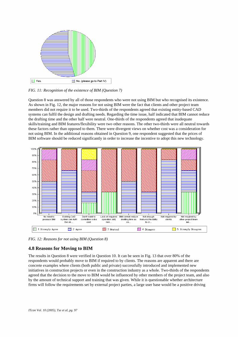
FIG. 11: Recognition of the existence of BIM (Question 7) Question 8 was answered by all of those respondents who were not using BIM but who recognised its existence. As shown in Fig. 12, the major reasons for not using BIM were the fact that clients and other project team members did not require it to be used. Two-thirds of the respondents agreed that existing entity-based CAD systems can fulfil the design and drafting needs. Regarding the time issue, half indicated that BIM cannot reduce the drafting time and the other half were neutral. One-thirds of the respondents agreed that inadequate skills/training and BIM features/flexibility were two other reasons. The other two-thirds were all neutral towards these factors rather than opposed to them. There were divergent views on whether cost was a consideration for not using BIM. In the additional reasons obtained in Question 9, one respondent suggested that the prices of BIM software should be reduced significantly in order to increase the incentive to adopt this new technology.
FIG. 12: Reasons for not using BIM (Question 8)
4.8 Reasons for Moving to BIM The results in Question 8 were verified in Question 10. It can be seen in Fig. 13 that over 80% of the respondents would probably move to BIM if required to by clients. The reasons are apparent and there are concrete examples where clients (both public and private) successfully introduced and implemented new initiatives in construction projects or even in the construction industry as a whole. Two-thirds of the respondents agreed that the decision to the move to BIM would be influenced by other members of the project team, and also by the amount of technical support and training that was given. While it is questionable whether architecture firms will follow the requirements set by external project parties, a large user base would be a positive driving
ITcon Vol. 10 (2005), Tse et al, pg. 97

force for the adoption of new technologies. The majority (over 80%) of the respondents also stated that they wanted to see large productivity gain software and half indicated that they wanted to see downstream applications of BIM. The results suggest that more efforts should be put into promoting the advantages of BIM over conventional entity-based CAD software, and into enabling the application programming interface as well as into promoting information interoperability. As collected in Question 11, other motivations include reducing the prices of BIM and providing a free trial period.
FIG. 13: Reasons for moving to BIM (Question 10)
4.9 Computer-Aided Design and Drafting Practice There are two main approaches in computer-aided design and drafting in architecture firms: i) Architects develop the design on papers, whereas draftsmen are responsible for all of the CAD inputs; ii) Architects develop the design with CAD, whereas draftsmen are mainly responsible for making the changes. The respondents were asked to indicate which approach best describes the practice in their companies, or to specify the common practice. Fig. 14 unambiguously shows that the separation of design and CAD drafting is the mainstream practice in about 86% of the respondents’ firms. It is an obstacle to the adoption of BIM, which is positioned to be not only an electronic drafting board but, more importantly, a design tool. In view of this, architects would need to switch from paper-based designs to BIM-based designs and to equip themselves with the necessary skills. Another possible scenario is that the spilt between design and drafting remains unchanged, but CAD draftsmen would use BIM as no more than an intelligent drawing production tool and the quality of the information generation by the model would be undermined.
I
FIG. 14: CAD design and drafting practice (Question 13)
Tcon Vol. 10 (2005), Tse et al, pg. 98
FIG. 15: Practice on providing CAD files forproject parties (Question 15)

4.10 Practice of Exchanging CAD Files Exchange The provision of electronic BIM files to other external project parties is essential to downstream applications of the building information. Fig. 15 shows that a large number of firms provide CAD files for free (58%) or for a fee (21%) ranging from HK$300 to HK$800 per file upon request. As revealed previously, these CAD files are deemed to be prepared using AutoCAD or MicroStation. If a project has 100 CAD files, the cost of obtaining the whole set of electronic drawings would be HK$30,000 to HK$80,000 (assuming that there is no extra fee to obtain subsequent updated files). It could be a small amount compared to the contract sums or the consultant fees, but might also be a barrier to the exchange of building information among project team members.
4.11 Knowledge of CAD Data Exchange Standards Fig. 16 presents the respondents’ knowledge of four major CAD data exchange standards. It reveals that the majority of the respondents were familiar with DXF but not with IFC, IGES and STEP. The result for STEP is unexpected as STEP has been unveiled for a much longer period of time than IFC.
FIG. 16: Knowledge of data exchange standards (Question 14)
5. CONCLUSIONS AND RECOMMENDATIONS The concepts of nD modelling are clear and sound. It is believed to be a way in which construction stakeholders can extract, share and reuse the information on electronic design throughout the lifecycle of the project. The catalyst for creating other design dimensions is a new generation of intelligent object-based CAD software commonly known as BIM. This paper reviewed the BIM solutions in the marketplace, with particular emphasis on the provision of built-in objects and data interfaces for third-party applications. The more important objective is to address the “Soft” aspects of using BIM. These include the people, cultural, process and technical factors affecting the uptake of BIM. The investigation was based on a questionnaire survey conducted in Hong Kong. Since architects play a leading role in establishing BIMs, the survey targeted CAD managers and architects in architectural firms. Although the survey focused on the situation in Hong Kong, the findings provide a basis for comparing similar surveys conducted around the world.
It is revealed that the uptake of BIM is still very low and that conventional entity-based CAD software (in particular AutoCAD and MicroStation) remain the de-facto drafting tools. The barriers to the use of BIM include the spilt between architecture design and drafting, inadequate objects and object customisation capability, a complicated and time-consuming modelling process, a lack of training and technical support, the cost of acquiring extra files and the unavailability of free trial software. Of all of these barriers, the separation of design and drafting is a common practice that is more difficult to solve than the technical barriers. More direct participation from the designers is expected in both BIM and nD modelling or the quality of the model
ITcon Vol. 10 (2005), Tse et al, pg. 99

information will be in question. To cope with such process re-engineering, more promotion should be given on the advantages of using BIM in the design process. It is recommended that there should be clear industry guidelines on charging for the provision of CAD files or, more preferably, clients may stipulate the free exchange of CAD data among project team members.
The findings indicate that most architects would be more proactive in adopting BIM if they could see a large gain in productivity over the use of conventional CAD systems and the downstream applications of the building information. According to the BIM users, the apparent reasons for using BIM is that different views and schedules can be generated and updated automatically and instantly. By contrast, slightly more than half of the non-BIM users had actually not heard about BIM. The others considered that entity-based CAD software can largely fulfil design and drafting needs and that BIM could not reduce the drafting time. These results highlight the areas that should be enhanced, stressed or clarified when promoting BIM. The findings also substantiate the view that clients and other members of the project team can play an influential role in the use of BIM. Promotion should therefore be directed to not only t o architects but also to clients and other consultants.
It is recommended that more user-friendly interfaces for embedding extra parameters into the modelling objects should be provided. BIM vendors should also support third-party development by enabling application programming interfaces and data exchange standards such as IFC and XML. Although IFC is a versatile standard, the loss or distortion of data during the export and import processes was recorded (Niemioja 2001). There should be strict compliance with IFC specifications when blending other design modules with IFC. Also, there is a need to further differentiate between ifcXML (promoted by all IFC Chapters) and aecXML (promoted by only the North American Chapter).
7. ACKNOWLEDGEMENTS This research was funded by the Postgraduate Research Scholarship of the Hong Kong Polytechnic University.
8. REFERENCES Aouad, G., Marshall-Ponting, A., Hamilton, A, Lee, A., Fu, C., Davey, C., Sexton, M., Kagiouglou, M., Sun,
M., Koh, I., Ormerod, M., Tzortzopoulos, P., Alexander, K., Sarshar, M., Bettes, M., Alshwi, M., Barrett, P., Brando, P., Cooper, R., Marvin, S., Fernando, T., Lam, Y.W., Wu, S. and Curwell, S. (2004) 3D to nD Modelling Project. Available at http://ndmodelling.scpm.salford.ac.uk/background.htm
ART (2004). Chief Architect. Advanced Relational Technology, Inc. Available at: http://www.chiefarchitect.com
Autodesk (2004a). Autodesk Homepage. Available at: http://www.autodesk.com
Autodesk (2004b). Rev It Up Promotion for Architectural Desktop. Available at: http://www3.autodesk.com/adsk/files/4624835_Rev_It_Up_Promo_for_ADT_FAQ.pdf
Autodesk (2004c). Autodesk Revit User Manual. Autodesk.
Bentley (2004a). Bentley Homepage. Available at: http://www.bentley.com
Bentley (2004b). Bentley Architecture – User Guide. Available at http://www.bentley.com
Björk Bo-Christer Löwnertz Kurt Kiviniemi Arto (1997) ISO DIS 13567 - The Proposed International Standard for Structuring Layers in Computer Aided Building Design, ITcon Vol. 2, pg. 32-55, http://www.itcon.org/1997/2
BLIS (2002) Building Lifecycle Interoperability Software. Available at: http://www.blis-project.org
Chuck, W. (1999) OLE DB and ODBC developer's guide. Foster City, Calif.
Day, M. (2002). Autodesk is Buying Revit. CAD Digest. Available at: http://www.caddigest.com/subjects/autocad/select/adesk_revit/adesk_revit.htm
DSC (2000) History of CAD. Dalton State College. Available at: http://cadlab.daltonstate.edu/historyofcad.pdf
ITcon Vol. 10 (2005), Tse et al, pg. 100

Eastman, C.M. (1999) Building product models : computer environments supporting design and construction. Boca Raton, Fla. : CRC Press.
ETWB (2004) Computer-Aided-Drafting Standard for Work Projects. Environment, Transport and Works Bureau, Hong Kong Government Special Administration Region. Available at: http://www.etwb.gov.hk/electronic_services/index.aspx?langno=1&nodeid=632
Fischer, M (2001) Introduction to 4D Research. Available at: http://www.stanford.edu/group/4D/index.shtml
Froese T (2003) Future directions for IFC-based interoperability, ITcon Vol. 8, Special Issue IFC - Product models for the AEC arena, pg. 231-246, http://www.itcon.org/2003/17
gbXML (2004) Green Building XML Schema. Available at: http://www.gbxml.org/
GeoPraxis (2004) Green BuildingStudio™ AEC DesignPractice Study 2004 – Final Report. Available at: http://www.geopraxis.com/
GDL (2004) GDL Alliance. Available at: http://www.gdlalliance.com/
Goldberg, H.E. (2003) New Tools Deliver BIM Data. Cadalyst. Dec 2003. Available at: http://aec.cadalyst.com/aec/article/articleDetail.jsp?id=99867
Goldberg, H.E. (2004) Autodesk Architectural Desktop 2004 – A Comprehensive Tutorial. Prentice Hall: N.J.
Grabowski, R. (2002) Autodesk Buys Revit - Frequently Asked Questions. Available at: http://www.caddigest.com/subjects/autocad/select/adesk_revit/faqs.htm
GraphiSoft (2004a) GraphiSoft Homepage. http://www.GraphiSoft.com
GraphiSoft (2004b) GraphiSoft ArchiCAD 9 Reference Guide. GraphiSoft.
GraphiSoft (2004c) GraphiSoft Plan ODBC Driver v1.0.0 Reference Manual. GraphiSoft
Graves, J. (2002) Press Release – AutoCAD to Acquire Revit Technology Corporation. Available at: http://usa.autodesk.com/adsk/servlet/item?siteID=452932&id=1156948
IAI (2004) International Alliance for Interoperability. Homepage. Available at: http://www.iai-international.org/iai_international/
Kam, C., Fischer, M., Hänninen, R., Karjalainen, A. and Laitinen, J. (2003) The product model and Fourth Dimension project. ITcon vol. 8, Special Issue - IFC - Product models for the AEC arena. pp. 137-166. Available at http://www.itcon.org/2003/12
Langdon, G.M. (2001) AllPlan 16.1 and new USA AllPlan support. Cadalyst. Available at: http://cadence.advanstar.com/newsletter/aec/0201_2.html
Lee, A., Wu, S. Aouad, G., Fu, C. (2002) “Towards nD Modelling.” Proceedings of the European Conference on Information and Communication Technology Advances and Innovation in the Knowledge Society (E-sm@art). University of Salford, U.K. 2002.
Liebich, T. (2001) XML Schema Language Binding of EXPRESS for ifcXML, International Alliance for Interoperability, http://www.iai-international.org/iai_international/Technical_Documents/documentation/IFCXML
Monster (2004) Revit Technology Corporation. Available at: http://company.monster.com/crsi/
Nemetschek (2004) Nemetschek AllPlan. Available at: http://www.nemetschek.com
NIBS (2004) U.S. National CAD Standard. National Institute of Building Sciences. Available at: http://www.nibs.org/
Niemioja, S. (2001) IFC Test - GraphiSoft ArchiCAD / Nemetschek AllPlanADT / Autodesk Revit. Available at: http://ccy.vtt.fi/vera/Documents/Spadex_Appendix_1.pdf
ITcon Vol. 10 (2005), Tse et al, pg. 101

Owolabi A, Anumba C J and El-Hamalawi A (2003) Architecture for implementing IFC-based online construction product libraries , ITcon Vol. 8, Special Issue IFC - Product models for the AEC arena , pg. 201-218, http://www.itcon.org/2003/15
Rischmoller, L., Fisher, M., Fox, R. and Alarcon, L. (2000) 4D Planning and Scheduling (4D-PS): Grounding Construction IT Research in Industry Practice. Proceedings of CIB W78 Conference on Construction Information Technology 2000: Taking the construction industry into the 21st century. June, Iceland.
Rönneblad A and Olofsson T (2003) Application of IFC in design and production of precast concrete constructions, ITcon Vol. 8, Special Issue IFC - Product models for the AEC arena , pg. 167-180, http://www.itcon.org/2003/13
Ross, S.S. (2002) Allplan Features. Cadalyst. Available at: http://www.cadalyst.com/cadalyst/article/articleDetail.jsp?id=90040
Softplan (2004) Softplan Homepage. Softplan System Inc. Available at: http://ww.softplan.com
Tse, T.C. and Wong, K.D. (2004) "A Case Study of the ISO 13567 CAD Layering Standard for Automated Quantity Measurement in Hong Kong", ITcon vol. 9, pp. 1-20. Available at http://www.itcon.org
Visual Engineering (2004) Visual Management of Data. Available at http://www.visual-engineering.com/index.html
ITcon Vol. 10 (2005), Tse et al, pg. 102

APPENDIX A: THE QUESTIONNAIRE
ITcon Vol. 10 (2005), Tse et al, pg. 103

ITcon Vol. 10 (2005), Tse et al, pg. 104

ITcon Vol. 10 (2005), Tse et al, pg. 105

ITcon Vol. 10 (2005), Tse et al, pg. 106

ITcon Vol. 10 (2005), Tse et al, pg. 107

ITcon Vol. 10 (2005), Tse et al, pg. 108

ITcon Vol. 10 (2005), Tse et al, pg. 109

ITcon Vol. 10 (2005), Tse et al, pg. 110