Experimental investigation of the strain rate dependence of SS2506 ...
Upload
truongtuyenCategory
view
215download
0
Modeling the strain-rate dependence of fatigue life of hot-pressed silicon nitride
Vinod Sharma, S. Nemat-Nasser *, Kenneth S. Vecchio
Center of Excellence for Advanced Materials, Department of AMES, 9500 Gilman Drive, University of California, San Diego, La Jolla,
CA 92093-0416, USA
Received 22 March 1997; revised version received 5 March 1998
Abstract
This paper presents the results of a micromechanical model used to explain the strain-rate dependence of the com-
pression fatigue lives of amorphous and crystalline grain boundary phase; denoted by ABP and CBP silicon nitrides,
respectively. When the strain-rate is changed from 400 to 0.01/s, the fatigue lives of both materials, evaluated at a peak
stress of 3.2 GPa, increased by more than two orders of magnitude (Sharma et al. (1996a,b)). The model is based on the
dynamic and quasi-static microstructural damage mechanisms observed in both materials. The microstructure of ABP
and CBP silicon nitrides is modeled as a simple composite in which silicon nitride grains are embedded in a continuous
network of the grain boundary phase. Since the subsurface fatigue cracks in both materials nucleate mainly from the
contact region between silicon nitride grains, contact stresses between adjacent silicon nitride grains are obtained, and
the frequency dependence of the fatigue lives of ABP and CBP silicon nitrides is explained on the basis of the strain-rate
sensitivity of the grain boundary phase. Ó 1998 Elsevier Science Ltd. All rights reserved.
1. Introduction
In recent work by the authors (Sharma et al.(1996a,b)), the results of an experimental investi-gation of the e�ects of the grain boundary phaseon the dynamic and quasi-static compression fa-tigue life of hot-pressed silicon nitrides are present-ed. The compression fatigue lives of amorphousgrain boundary phase (ABP) and crystalline grainboundary phase (CBP) silicon nitrides are evaluat-ed at strain-rates of 0.01, 0.1 and 400/s. Table 1summarizes the results of the experiments. ABPsilicon nitride was ¯uxed with 6 wt% Y2O3 and 3wt% Al2O3, whereas CBP silicon nitride was ¯uxed
with 8 wt% Y2O3 and 1 wt% Al2O3. At a strain-rate of 400/s, the fatigue life of ABP silicon nitride(104 cycles) is observed to be superior to the fa-tigue life of CBP silicon nitride (44 cycles). Whenthe strain-rate is decreased from 400 to 0.01/s,the fatigue lives of both materials increases bymore than two orders of magnitude and the di�er-ence in the fatigue life of ABP silicon nitride(14,000 cycles) and CBP silicon nitride (12,000 cy-cles) was found to be relatively less signi®cant. Theobserved signi®cant di�erences in the fatigue livesbetween 400 and 0.01/s strain-rates was accreditedto the di�erences in the energy loss, which is givenby the enclosed area within the axial stress±straincurve, in a typical compression fatigue cycle. Theenergy loss per cycle, in samples from both materi-als, at a strain-rate of 0.01/s was observed to be
Mechanics of Materials 29 (1998) 253±273
* Corresponding author. E-mail: [email protected].
0167-6636/98/$ ± see front matter Ó 1998 Elsevier Science Ltd. All rights reserved.
PII: S 0 1 6 7 - 6 6 3 6 ( 9 8 ) 0 0 0 2 4 - 6

insigni®cant compared to the energy loss in a typ-ical fatigue cycle at 400/s.
For ABP and CBP silicon nitrides, the micro-cracks and dislocations were observed to nucleatemainly from the contact region between two sili-con nitride grains. The grains of silicon nitrideare generally separated by a grain boundary phasewhich can be as thin as 1±8 nm (Ahn and Thomas,1983). For the purpose of numerical analysis, themicrostructure of ABP and CBP silicon nitridesis modeled as a composite in which silicon nitridegrains are surrounded by a thin boundary phaselayer.
When a ceramic is subjected to compressionloading, local shear stresses may act on the faceof pre-existing ¯aws. The shear stress acting onthe ¯aws causes the cracks to grow along the ap-plied compression direction under a local tensile®eld (Nemat-Nasser and Horii, 1982; Horii andNemat-Nasser, 1986; Ashby and Hallam, 1986).To ®nd the critical sites where fatigue cracks arelikely to nucleate, the maximum in-plane shearstress, in the vicinity of contact region, is foundby varying the contact radius and the thicknessof the intergranular layer.
The e�ect of high pressure on amorphous silicawas studied by Bridgeman and Simon (1953). Theyobserved that amorphous silica undergoes plasticdeformation at pressures of the order of 1 to 10GPa. Since silica is present in the grain boundaryphases, and very high stresses are generated atthe contact regions, the grain boundary phasesare assumed to have strain-rate sensitive plasticity.The strain-rate dependence of fatigue life is numer-ically modeled based on the strain-rate sensitivityof the grain boundary phases, and the manner bywhich the forces are transmitted over the contact
area between adjacent grains. In other words, thechange in the maximum in-plane shear stress is ex-amined by changing the yield strength of the grainboundary phases to mimic the behavior of a strain-rate sensitive material.
In order to ®nd the elastic constants of amor-phous and crystalline grain boundary phases, anattempt was made to produce these materials fromappropriate oxide powders. However, the attemptwas not very successful due to the lack of properfacilities. Thus, the average elastic properties ofthe amorphous grain boundary phase, silicon nit-ride grains and the crystalline grain boundaryphase are estimated theoretically. These propertiesare then used to ®nd the contact stresses as a func-tion of the contact radius and the thickness of thegrain boundary phase.
2. Estimation of elastic properties of silicon nitridegrains and amorphous and crystalline grain boun-
dary phase
To evaluate the properties of grain boundaryphases, it is important to know their composition.The composition of each grain boundary phase de-pends upon the relative amounts of sintering aids,as well as upon the impurity content, concentra-tion of silica present on silicon nitride particles,and other factors. Normally, the concentrationof oxygen in submicron silicon nitride particlesvaries from 1±3 wt%. If oxygen were to be presentonly in the form of silica, then the concentration ofsilica in silicon nitride particles varies from about2±6 wt%. In estimating the elastic constants, theconcentration of silica in silicon nitride powder istaken to be slightly under 3.5 wt%, which corre-sponds to 3 wt% silica in ABP and CBP silicon nit-rides. Thus, the composition of the ABP siliconnitride is taken to be: 88 wt% Si3N4, 3 wt% SiO2,6 wt% Y2O3, and 3 wt% Al2O3, whereas the com-position of the CBP silicon nitride is taken to be:88 wt% Si3N4, 3 wt% SiO2, 8 wt% Y2O3, and 1wt% Al2O3. In reality, some of silicon nitride isalso present in the grain boundary phase, whichis neglected here in the estimation of the propertiesof intergranular phases and silicon nitride grains.Small additions of silicon nitride to the intergran-
Table 1
Variation in compression fatigue lives of ABP and CBP silicon
nitrides as a function of strain rate.
Strain rate ABP silicon nitride CBP silicon nitride
400/sec 104 cycles 44 cycles
400/sec 91 cycles 33 cycles
0.1/sec 9500 cycles 3500 cycles
0.01/sec 14030 cycles 11965 cycles
0.01/sec 12150 cycles 10210 cycles
254 V. Sharma et al. / Mechanics of Materials 29 (1998) 253±273
ular phase increase the hardness and modulus ofthe grain boundary phase. Thus, the estimatedmoduli of the crystalline and amorphous grainboundary phase are expected to be lower thanthe actual moduli.
2.1. Estimate of the elastic properties of amorphousgrain boundary phase
The elastic properties of certain oxide glasseswere calculated from their chemical compositionby Mackishima and Mackenzie (1973, 1975).Their calculation was based on the considerationof the packing density and the dissociation energyof the oxide constituents per unit volume. Accord-ing to them, the Young modulus of an oxide glassis given by
E � 83:6Vt
Xn
i�1
GiXi; �1�
where Gi is the dissociation energy per unit volumeof component i, Xi is the mole fraction of the ithcomponent, and Vt is the packing density. InEq. (1), if G is measured in kcal/cm3 then theYoung modulus has the units of kbar
The packing density is given by
Vt � qM
Xn
i�1
ViXi; �2�
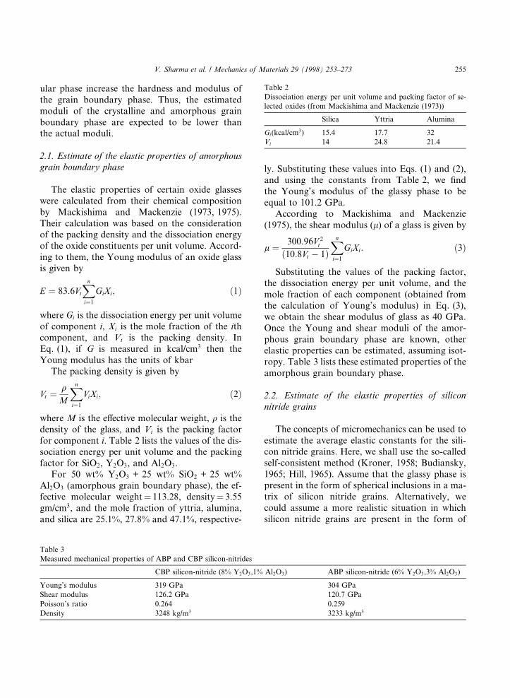
where M is the e�ective molecular weight, q is thedensity of the glass, and Vi is the packing factorfor component i. Table 2 lists the values of the dis-sociation energy per unit volume and the packingfactor for SiO2, Y2O3, and Al2O3.
For 50 wt% Y2O3 + 25 wt% SiO2 + 25 wt%Al2O3 (amorphous grain boundary phase), the ef-fective molecular weight� 113.28, density� 3.55gm/cm3, and the mole fraction of yttria, alumina,and silica are 25.1%, 27.8% and 47.1%, respective-
ly. Substituting these values into Eqs. (1) and (2),and using the constants from Table 2, we ®ndthe Young's modulus of the glassy phase to beequal to 101.2 GPa.
According to Mackishima and Mackenzie(1975), the shear modulus (l) of a glass is given by
l � 300:96V 2t
�10:8Vt ÿ 1�Xn
i�1
GiXi: �3�
Substituting the values of the packing factor,the dissociation energy per unit volume, and themole fraction of each component (obtained fromthe calculation of Young's modulus) in Eq. (3),we obtain the shear modulus of glass as 40 GPa.Once the Young and shear moduli of the amor-phous grain boundary phase are known, otherelastic properties can be estimated, assuming isot-ropy. Table 3 lists these estimated properties of theamorphous grain boundary phase.
2.2. Estimate of the elastic properties of siliconnitride grains
The concepts of micromechanics can be used toestimate the average elastic constants for the sili-con nitride grains. Here, we shall use the so-calledself-consistent method (Kroner, 1958; Budiansky,1965; Hill, 1965). Assume that the glassy phase ispresent in the form of spherical inclusions in a ma-trix of silicon nitride grains. Alternatively, wecould assume a more realistic situation in whichsilicon nitride grains are present in the form of
Table 2
Dissociation energy per unit volume and packing factor of se-
lected oxides (from Mackishima and Mackenzie (1973))
Silica Yttria Alumina
Gi(kcal/cm3) 15.4 17.7 32
Vi 14 24.8 21.4
Table 3
Measured mechanical properties of ABP and CBP silicon-nitrides
CBP silicon-nitride (8% Y2O3,1% Al2O3) ABP silicon-nitride (6% Y2O3,3% Al2O3)
Young's modulus 319 GPa 304 GPa
Shear modulus 126.2 GPa 120.7 GPa
Poisson's ratio 0.264 0.259
Density 3248 kg/m3 3233 kg/m3
V. Sharma et al. / Mechanics of Materials 29 (1998) 253±273 255

spherical inclusions in a matrix of the glassy phase.In the self-consistent method, the roles of the twophases are interchangeable and the elastic con-stants, estimated by self-consistent method, arenot a�ected by this choice. If the matrix and inclu-sions are assumed to be linearly elastic and isotro-pic, then the elastic constants of silicon nitridegrains can be estimated either by a dilute distribu-tion scheme in which the interaction between in-clusions is neglected, or by the self-consistentscheme which accounts to some extent for the in-teraction between grains. Since the volume frac-tion of the glassy phase is greater than 10%, theself-consistent scheme is used to estimate the aver-age elastic constants for silicon nitride grains. Ac-cording to this scheme, the elastic constants of thecomposite material (grains and grain boundaryphase) are related to the elastic constants of the in-clusions and the matrix through the following rela-tions (Nemat-Nasser and Hori, 1993):
KK� 1ÿ f
K�K ÿ KI�K�K ÿ KI�
KK ÿ KI
ÿ s1
� �ÿ1
; �4�
ll� 1ÿ f
l�lÿ lI�l�lÿ lI�
llÿ lI
ÿ s2
� �ÿ1
; �5�
where f is the volume fraction of inclusions (glassyphase), and K; l; K; l; KI, and lI are the bulkand shear moduli of the matrix, composite, and in-clusions, respectively. s1 and s2 are the componentsof Eshelby's tensor for spherical inclusions, givenby,
s1 � �1� m�3�1ÿ m� ; �6�
s2 � 2�4ÿ 5m�15�1ÿ m� ; �7�
where m is Poisson's ratio of the composite (ABPsilicon nitride).
The elastic constants of ABP and CBP siliconnitrides were calculated by measuring the pulseecho sound speed in the longitudinal and shearmodes. Table 3 (Sharma et al., 1994) lists the mea-sured elastic constants of ABP and CBP siliconnitrides. By knowing the elastic constants ofABP silicon nitride (composite) and glassy phase(inclusion), Eqs. (4) and (5) can be solved for bulkand shear moduli of silicon nitride grains. The es-timated values of the aggregate properties of sili-con nitride grains are listed in Table 4.
2.3. Estimate of the elastic constants of crystallinegrain boundary phase
Since the properties of CBP silicon nitride(composite) and silicon nitride grains (matrix) areknown, Eqs. (4) and (5) can be used to estimatethe properties of the crystalline grain boundaryphase (inclusion). The elastic constants of the crys-talline grain boundary phase are listed in Table 4.
It can be observed from Tables 3 and 4 thatwhile most of the properties of ABP and CBP sil-icon nitrides fall between the properties of siliconnitride grains and amorphous/crystalline grainboundary phase, the Poisson ratio of ABP siliconnitride is lower than the Poisson ratio of siliconnitride grains and the glassy phase. This is due tothe self-consistent model used to determine theproperties of silicon nitride grains from the proper-ties of ABP silicon nitride and the glassy phase.This model ensures that the modulus of the com-posite falls between the modulus of the matrixand the inclusion. Since Poisson's ratio is a dimen-sionless number, it is not constrained by the prop-erties of the inclusions and the matrix under theself-consistent scheme.
Table 4
Estimated elastic properties of amorphous boundary phase, silicon-nitride grains, and crystalline boundary phase
ABP Silicon-nitride CBP
Young's modulus 101.2 GPa 345.6 GPa 162.6 GPa
Shear modulus 40 GPa 137 GPa 62.8 GPa
Poisson's ratio 0.264 0.261 0.295
Bulk modulus 71.4 GPa 241 GPa 132 GPa
256 V. Sharma et al. / Mechanics of Materials 29 (1998) 253±273
3. Modeling the frequency dependence of fatigue
lives of ABP and CBP silicon nitrides
In this section, the frequency dependence of fa-tigue lives of ABP and CBP silicon nitrides is mod-eled based on the strain-rate sensitivity of theamorphous and crystalline grain boundary phases.Since fatigue cracks in ABP and CBP silicon nit-rides initiate from contact regions between two
grains, the contact stresses between adjacent sili-con nitride grains, with a thin intergranular layerin between, are calculated numerically.
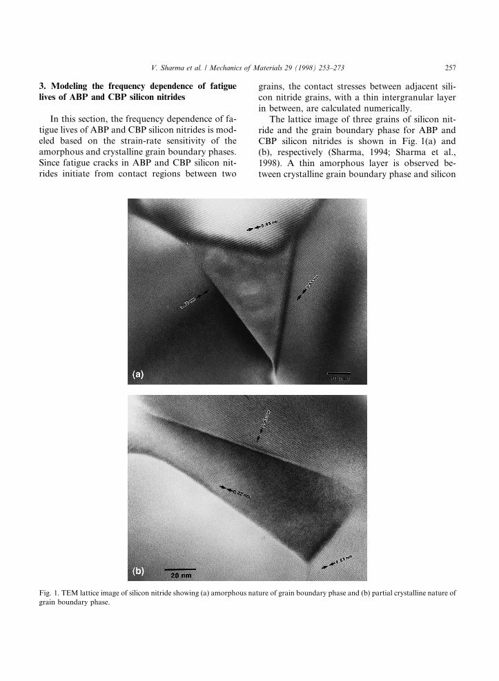
The lattice image of three grains of silicon nit-ride and the grain boundary phase for ABP andCBP silicon nitrides is shown in Fig. 1(a) and(b), respectively (Sharma, 1994; Sharma et al.,1998). A thin amorphous layer is observed be-tween crystalline grain boundary phase and silicon
Fig. 1. TEM lattice image of silicon nitride showing (a) amorphous nature of grain boundary phase and (b) partial crystalline nature of
grain boundary phase.
V. Sharma et al. / Mechanics of Materials 29 (1998) 253±273 257
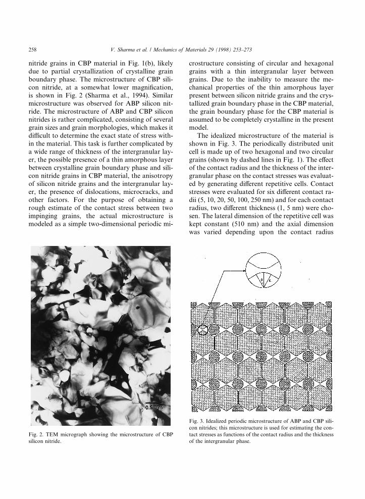
nitride grains in CBP material in Fig. 1(b), likelydue to partial crystallization of crystalline grainboundary phase. The microstructure of CBP sili-con nitride, at a somewhat lower magni®cation,is shown in Fig. 2 (Sharma et al., 1994). Similarmicrostructure was observed for ABP silicon nit-ride. The microstructure of ABP and CBP siliconnitrides is rather complicated, consisting of severalgrain sizes and grain morphologies, which makes itdi�cult to determine the exact state of stress with-in the material. This task is further complicated bya wide range of thickness of the intergranular lay-er, the possible presence of a thin amorphous layerbetween crystalline grain boundary phase and sili-con nitride grains in CBP material, the anisotropyof silicon nitride grains and the intergranular lay-er, the presence of dislocations, microcracks, andother factors. For the purpose of obtaining arough estimate of the contact stress between twoimpinging grains, the actual microstructure ismodeled as a simple two-dimensional periodic mi-
crostructure consisting of circular and hexagonalgrains with a thin intergranular layer betweengrains. Due to the inability to measure the me-chanical properties of the thin amorphous layerpresent between silicon nitride grains and the crys-tallized grain boundary phase in the CBP material,the grain boundary phase for the CBP material isassumed to be completely crystalline in the presentmodel.
The idealized microstructure of the material isshown in Fig. 3. The periodically distributed unitcell is made up of two hexagonal and two circulargrains (shown by dashed lines in Fig. 1). The e�ectof the contact radius and the thickness of the inter-granular phase on the contact stresses was evaluat-ed by generating di�erent repetitive cells. Contactstresses were evaluated for six di�erent contact ra-dii (5, 10, 20, 50, 100, 250 nm) and for each contactradius, two di�erent thickness (1, 5 nm) were cho-sen. The lateral dimension of the repetitive cell waskept constant (510 nm) and the axial dimensionwas varied depending upon the contact radius
Fig. 2. TEM micrograph showing the microstructure of CBP
silicon nitride.
Fig. 3. Idealized periodic microstructure of ABP and CBP sili-
con nitrides; this microstructure is used for estimating the con-
tact stresses as functions of the contact radius and the thickness
of the intergranular phase.
258 V. Sharma et al. / Mechanics of Materials 29 (1998) 253±273
and thickness of the intergranular phase betweenhexagonal grains. The distance between parallelsides of the hexagonal grains was kept constantat 500 nm. The area fraction of the grain boundaryphase was set at about 11%, by varying the diam-eter of the circular grains.
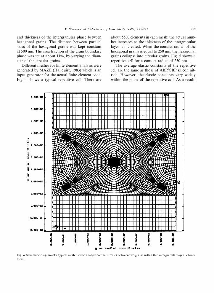
Di�erent meshes for ®nite element analysis weregenerated by MAZE (Hallquist, 1983) which is aninput generator for the actual ®nite element code.Fig. 4 shows a typical repetitive cell. There are
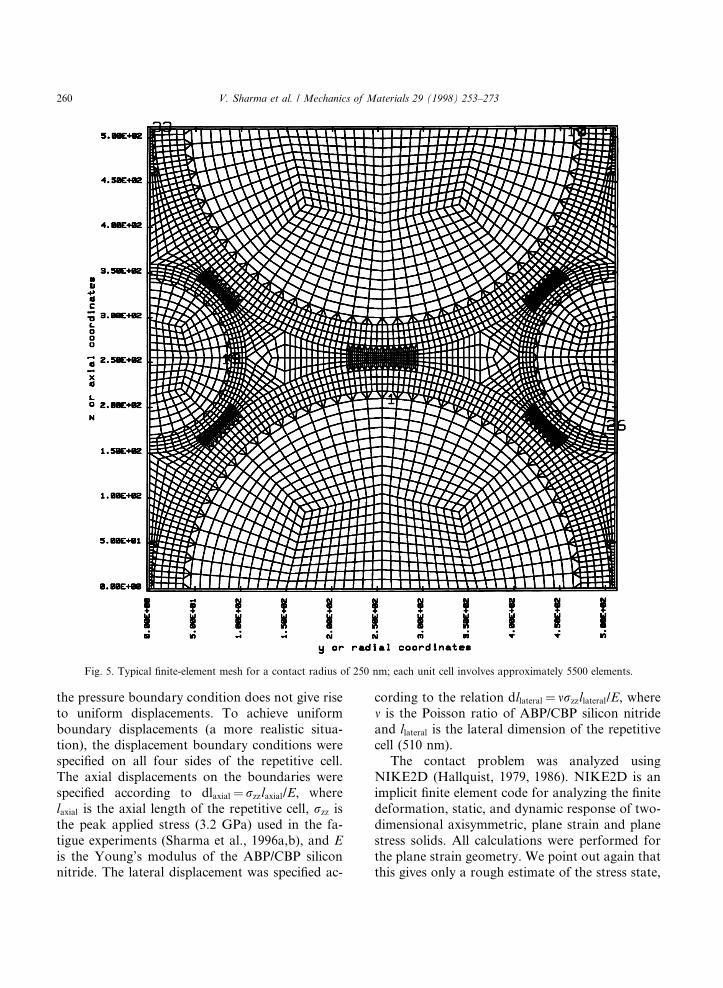
about 5500 elements in each mesh; the actual num-ber increases as the thickness of the intergranularlayer is increased. When the contact radius of thehexagonal grains is equal to 250 nm, the hexagonalgrains collapse into circular grains. Fig. 5 shows arepetitive cell for a contact radius of 250 nm.
The average elastic constants of the repetitivecell are the same as those of ABP/CBP silicon nit-ride. However, the elastic constants vary widelywithin the plane of the repetitive cell. As a result,
Fig. 4. Schematic diagram of a typical mesh used to analyze contact stresses between two grains with a thin intergranular layer between
them.
V. Sharma et al. / Mechanics of Materials 29 (1998) 253±273 259
the pressure boundary condition does not give riseto uniform displacements. To achieve uniformboundary displacements (a more realistic situa-tion), the displacement boundary conditions werespeci®ed on all four sides of the repetitive cell.The axial displacements on the boundaries werespeci®ed according to dlaxial� rzzlaxial/E, wherelaxial is the axial length of the repetitive cell, rzz isthe peak applied stress (3.2 GPa) used in the fa-tigue experiments (Sharma et al., 1996a,b), and Eis the Young's modulus of the ABP/CBP siliconnitride. The lateral displacement was speci®ed ac-
cording to the relation dllateral� mrzzllateral/E, wherem is the Poisson ratio of ABP/CBP silicon nitrideand llateral is the lateral dimension of the repetitivecell (510 nm).
The contact problem was analyzed usingNIKE2D (Hallquist, 1979, 1986). NIKE2D is animplicit ®nite element code for analyzing the ®nitedeformation, static, and dynamic response of two-dimensional axisymmetric, plane strain and planestress solids. All calculations were performed forthe plane strain geometry. We point out again thatthis gives only a rough estimate of the stress state,
Fig. 5. Typical ®nite-element mesh for a contact radius of 250 nm; each unit cell involves approximately 5500 elements.
260 V. Sharma et al. / Mechanics of Materials 29 (1998) 253±273
as the actual situation is neither two-dimensionalnor periodic.
The elastic constants for crystalline and amor-phous grain boundary phases and silicon nitridegrains, estimated in the previous section, were usedas an input to NIKE2D. The output of NIKE2Dwas used in ORION (Hallquist and Levatin,1985), which is a post-processor for NIKE2D, to®nd the contact stresses. Once the stress tensorwithin each element is known, the maximum in-plane shear stress {(syz)max} was found from thefollowing relation:
�syz�max ���������������������������������������
rzz ÿ ryy
2
n o2
� s2yz
r; �8�
where rzz is the axial stress, ryy is the lateral stressand syz is the shear stress within an element.
4. Upper and lower bounds on the elastic moduli
based on the periodic microstructure
Bounds on the overall elastic moduli of a peri-odic microstructure can be found by homogenizingthe microstructure and minimizing the strain ener-gy and complementary strain energy of the ho-mogenized microstructure (Nemat-Nasser et al.,1982; Nemat-Nasser and Hori, 1993). The micro-structure can be homogenized by choosing an arbi-trary reference material and by prescribing suitableeigenstrain (eigenstress) ®elds to accommodate thematerial mismatch. If the matrix is sti�er than theinclusion, then the upper bound is obtained bychoosing the reference material to be the same asthe matrix material, and the lower bound is ob-tained when the reference material is chosen asthe inclusion material. For a two-phase compositematerial, the upper and lower bounds on the elas-tic moduli are given by (Nemat-Nasser and Hori,1993; Nemat-Nasser et al., 1993),
C� � CM � fX �CX ÿ CM�ÿ1 � fXCXX�CM�
h iÿ1
; �9�
Cÿ � CX � �1ÿ fX� �CM ÿ CX�ÿ1
�� f 2
X
�1ÿ fX�CXX�CX�
�ÿ1
; �10�
where fX is the volume fraction of inclusions, CM
and CX are the elasticity tensor for matrix and in-clusions, respectively, and CXX is the function ofthe reference elasticity tensor and the geometryof the inclusion.
Universal upper and lower bounds can be ob-tained based on only the volume fraction of the in-clusions, without considering the geometry of theinclusion in the calculation of CXX. The CXX matrixin this case is given by the following relations (Ne-mat-Nasser and Hori, 1993):
fXCXXiijj � �1ÿ fX� �1ÿ 2m�
2l�1ÿ m� ; �11a�
fXCXXijij � �1ÿ fX� �3ÿ 4m�
2l�1ÿ m� ; �11b�
where l is the shear modulus and m is Poisson's ra-tio of the reference material.
For an isotropic material, the two-dimensionalsti�ness matrix for plane strain geometry is given by
E�1ÿ m��1� m��1ÿ 2m�
Em�1� m��1ÿ 2m� 0
Em�1� m��1ÿ 2m�
E�1ÿ m��1� m��1ÿ 2m� 0
0 0 E�1� m�
�����������
�����������; �12�
where E is the Young modulus of the referencematerial. The elasticity tensor for the matrix andthe inclusion can be obtained by substituting Eand n into the above equation. Substituting CM,CX, and Eq. (12) into Eqs. (9) and (10), the univer-sal upper and lower bounds are found as,
C�U �
540:12 282:68 0:0000
282:68 540:12 0:0000
0:0000 0:0000 334:80
��������������; �13a�
CÿU �
374:71 117:28 0:0000
117:28 374:71 0:0000
0:0000 0:0000 223:84
��������������; �13b�
If the geometry of the inclusion is also account-ed for in the determination of the bounds, thenCXX is given by the following relation:
CXX �X�1
n
gX�ÿn�gX�n�C�n;C�: �14�
V. Sharma et al. / Mechanics of Materials 29 (1998) 253±273 261
In Eq. (14) the term associated with ni.ni� 0 is ex-cluded from the summation (ni� nip/ai, i� 1, 2, inot summed; where ni is an integer; and ai is thedimension of the unit cell in the ith direction).The e�ect of the inclusion geometry is fully ac-counted for in the g-integral de®ned by
g�n� � 1
VXX
Zexp�in:x� dx: �15�
For an isotropic material, C�n;C� is given bythe following relation:
C�n;C� � 1
lsym�n 1�2� n��
ÿ 1
2�1ÿ m� n n n n
�; �16�
where n � n=jnj � n=�������n:np
:The lower and upper bounds on the elastic
moduli can be found by substituting Eq. (14) intoEqs. (9) and (10). To this end, the intergranularphase (inclusion) of the unit cell shown in Fig. 2was divided into approximately 1200 elements.To calculate the g-integral, each of the 1200 ele-ments was approximated by a square. The term in-volving the geometry of the inclusions, given byEq. (14), is evaluated for two square elements Xr
and Xs with dimensions lr and ls and with centersat xr
0 and xs0, respectively. The result is,
gX�n�gX�ÿn� � cosfn � �xr0 ÿ xs
0�g
16 sin�n1lr=2� sin�n2lr=2� sin�n1ls=2� sin�n2ls=2�n2
1n22l2
r l2s
( ):
�17�Substituting Eqs. (17) and (16) into Eq. (14),
CXX can be calculated numerically when the refer-ence material is chosen to be either the matrix orthe inclusion. Since the series in Eq. (14) convergesrather fast, n1 and n2 were varied from )50 to +50.Once CXX is known, the upper and lower boundson the elastic moduli can be obtained fromEqs. (9) and (10). This gives,
C� �
399:68 143:77 0:0000
143:77 399:68 0:0000
0:0000 0:0000 258:11
��������������; �18a�
Cÿ �399:10 144:36 0:0000
144:36 399:10 0:0000
0:0000 0:0000 258:82
��������������: �18b�
The upper and lower bounds are essentially thesame (the di�erence between any two elements be-ing less than 0.4% which is within the numerical er-rors). These bounds lie between the universalbounds. For a composite having a periodic micro-structure, these bounds give a better estimate ofthe overall properties compared to the dilute distri-bution and self-consistent schemes.
Contact stresses were found for two di�erentcases: (a) elastic silicon nitride grains and elasticgrain boundary phases, and (b) elastic silicon nit-ride grains and strain-rate sensitive grain boun-dary phases.
5. Elastic silicon nitride grains, elastic grain boun-dary phase
In order to ®nd the critical sites within the micro-structure where fatigue cracks are likely to initiate,the maximum in-plane shear stress between contact-ing grains is calculated as a function of the contactradius and the thickness of the intergranular layer.Fig. 6 ((a) and (b)) show the variation of the maxi-mum in-plane shear stress on the surface of the sili-con nitride grains for CBP silicon nitride, for 1 and 5nm thickness of the intergranular layer, respective-ly. The abscissa of these ®gures represents the dis-tance along the surface of the grain (measuredfrom the contact point) normalized by (2pR/360),where R is the contact radius. In other words, thepoints on the surface of the hexagonal grains arerepresented by an angle that is measured counter-clockwise from the contact point.
When the thickness of the intergranular layer issmall (1 nm), then the maximum in-plane shearstress does not occur at the contact point (h� 0),but at a distance from it. As the thickness is in-creased, the maximum in-plane shear stress occursat the contact point for grains with contact radiusless than or comparable to the thickness of the in-tergranular layer. For a ®xed contact radius, aslight increase in the maximum in-plane shearstress with increasing intergranular thickness, was
262 V. Sharma et al. / Mechanics of Materials 29 (1998) 253±273
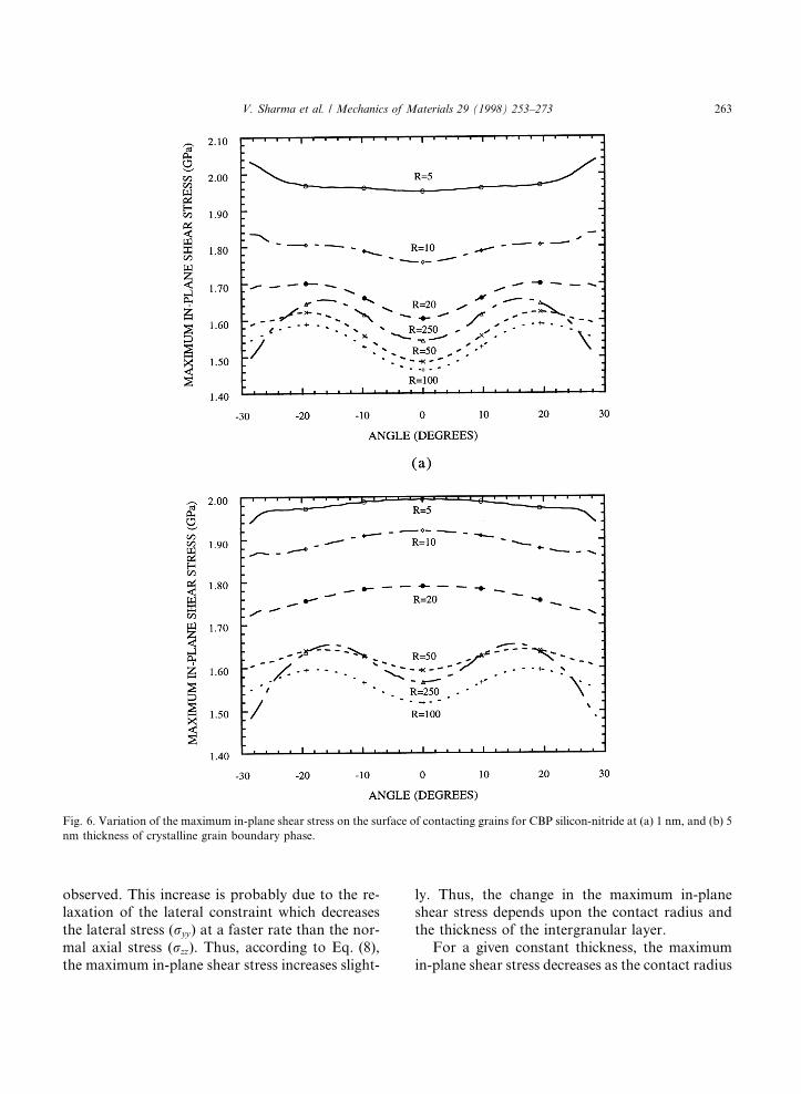
observed. This increase is probably due to the re-laxation of the lateral constraint which decreasesthe lateral stress (ryy) at a faster rate than the nor-mal axial stress (rzz). Thus, according to Eq. (8),the maximum in-plane shear stress increases slight-
ly. Thus, the change in the maximum in-planeshear stress depends upon the contact radius andthe thickness of the intergranular layer.
For a given constant thickness, the maximumin-plane shear stress decreases as the contact radius
Fig. 6. Variation of the maximum in-plane shear stress on the surface of contacting grains for CBP silicon-nitride at (a) 1 nm, and (b) 5
nm thickness of crystalline grain boundary phase.
V. Sharma et al. / Mechanics of Materials 29 (1998) 253±273 263
is increased to 100 nm. However, the maximum in-plane shear stress for a contact radius of 250 nmis greater than that for 50 nm and 100 nm contactradii at 1 and 5 nm intergranular layer thickness.For a contact radius of 250 nm, the grain boun-dary phase is more uniformly distributed (alongthe y-axis) compared to 50 and 100 nm contact ra-dii. For a ®xed lateral displacement, as the concen-tration of the soft phase along the y-axis, in thevicinity of contact region increases, the lateral con-straint (ryy) increases. An increase in the lateralconstraint decreases the maximum in-plane shearstress, according to Eq. (8). In fact, if the elasticproperties of the circular grains are chosen to bethe same as those of the grain boundary phase,then the maximum in-plane shear stress decreasesconsiderably, likely due to a greater lateral con-straint. The diameter of the circular grains also af-fects the maximum in-plane shear stress. Themaximum in-plane shear stress increases as the di-ameter of the circular grains increases. Thus, for acontact radius of 250 nm (smaller concentration ofsoft phase along the y-axis around the contact re-gion), the maximum in-plane shear stress is greaterthan that for a contact radius of 100 nm.
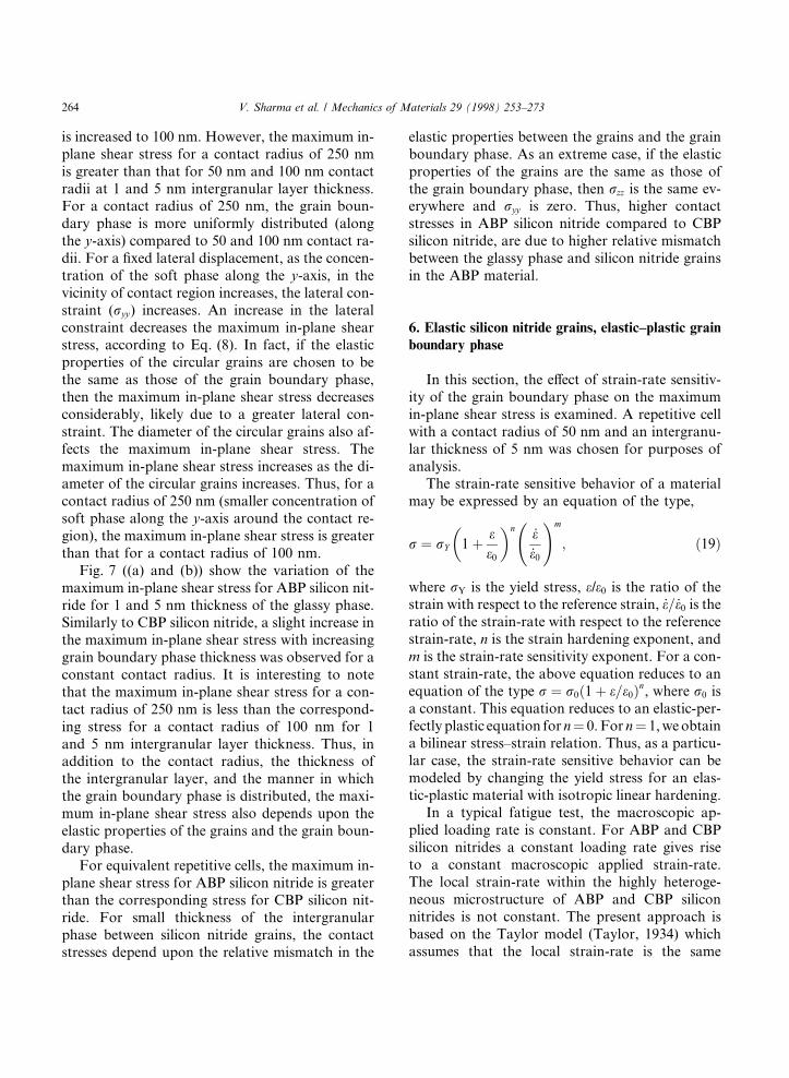
Fig. 7 ((a) and (b)) show the variation of themaximum in-plane shear stress for ABP silicon nit-ride for 1 and 5 nm thickness of the glassy phase.Similarly to CBP silicon nitride, a slight increase inthe maximum in-plane shear stress with increasinggrain boundary phase thickness was observed for aconstant contact radius. It is interesting to notethat the maximum in-plane shear stress for a con-tact radius of 250 nm is less than the correspond-ing stress for a contact radius of 100 nm for 1and 5 nm intergranular layer thickness. Thus, inaddition to the contact radius, the thickness ofthe intergranular layer, and the manner in whichthe grain boundary phase is distributed, the maxi-mum in-plane shear stress also depends upon theelastic properties of the grains and the grain boun-dary phase.
For equivalent repetitive cells, the maximum in-plane shear stress for ABP silicon nitride is greaterthan the corresponding stress for CBP silicon nit-ride. For small thickness of the intergranularphase between silicon nitride grains, the contactstresses depend upon the relative mismatch in the
elastic properties between the grains and the grainboundary phase. As an extreme case, if the elasticproperties of the grains are the same as those ofthe grain boundary phase, then rzz is the same ev-erywhere and ryy is zero. Thus, higher contactstresses in ABP silicon nitride compared to CBPsilicon nitride, are due to higher relative mismatchbetween the glassy phase and silicon nitride grainsin the ABP material.
6. Elastic silicon nitride grains, elastic±plastic grainboundary phase
In this section, the e�ect of strain-rate sensitiv-ity of the grain boundary phase on the maximumin-plane shear stress is examined. A repetitive cellwith a contact radius of 50 nm and an intergranu-lar thickness of 5 nm was chosen for purposes ofanalysis.
The strain-rate sensitive behavior of a materialmay be expressed by an equation of the type,
r � rY 1� ee0
� �n _e_e0
!m
; �19�
where rY is the yield stress, e/e0 is the ratio of thestrain with respect to the reference strain, _e= _e0 is theratio of the strain-rate with respect to the referencestrain-rate, n is the strain hardening exponent, andm is the strain-rate sensitivity exponent. For a con-stant strain-rate, the above equation reduces to anequation of the type r � r0�1� e=e0�n, where r0 isa constant. This equation reduces to an elastic-per-fectly plastic equation for n� 0. For n� 1, we obtaina bilinear stress±strain relation. Thus, as a particu-lar case, the strain-rate sensitive behavior can bemodeled by changing the yield stress for an elas-tic-plastic material with isotropic linear hardening.
In a typical fatigue test, the macroscopic ap-plied loading rate is constant. For ABP and CBPsilicon nitrides a constant loading rate gives riseto a constant macroscopic applied strain-rate.The local strain-rate within the highly heteroge-neous microstructure of ABP and CBP siliconnitrides is not constant. The present approach isbased on the Taylor model (Taylor, 1934) whichassumes that the local strain-rate is the same
264 V. Sharma et al. / Mechanics of Materials 29 (1998) 253±273
as the overall strain-rate. Thus, the in-planeshear stress is obtained assuming that the localstrain-rate is the same as the macroscopic appliedstrain-rate which is a constant. The model can be
re®ned to take care of the local strain-rates to ex-plain the di�erences in the strain-rate dependenceof the fatigue life of silicon nitride, using a concen-tration tensor (Nemat-Nasser and Hori, 1993), but
Fig. 7. Variation of the maximum in-plane shear stress on the surface of contacting grains for ABP silicon-nitride at (a) 1 nm, and (b) 5
nm thickness of amorphous grain boundary phase.
V. Sharma et al. / Mechanics of Materials 29 (1998) 253±273 265
for the present purposes, it is felt that the Tylormodel is adequate.
The elastic-plastic behavior will thus be repre-sented by the following equation:
rY � r0 � EPeP; �20�
where r0 is the initial e�ective yield stress, rY is thecurrent e�ective yield stress, eP is the e�ective plas-tic strain, and EP is the hardening modulus (slopeof yield stress-e�ective plastic strain curve).
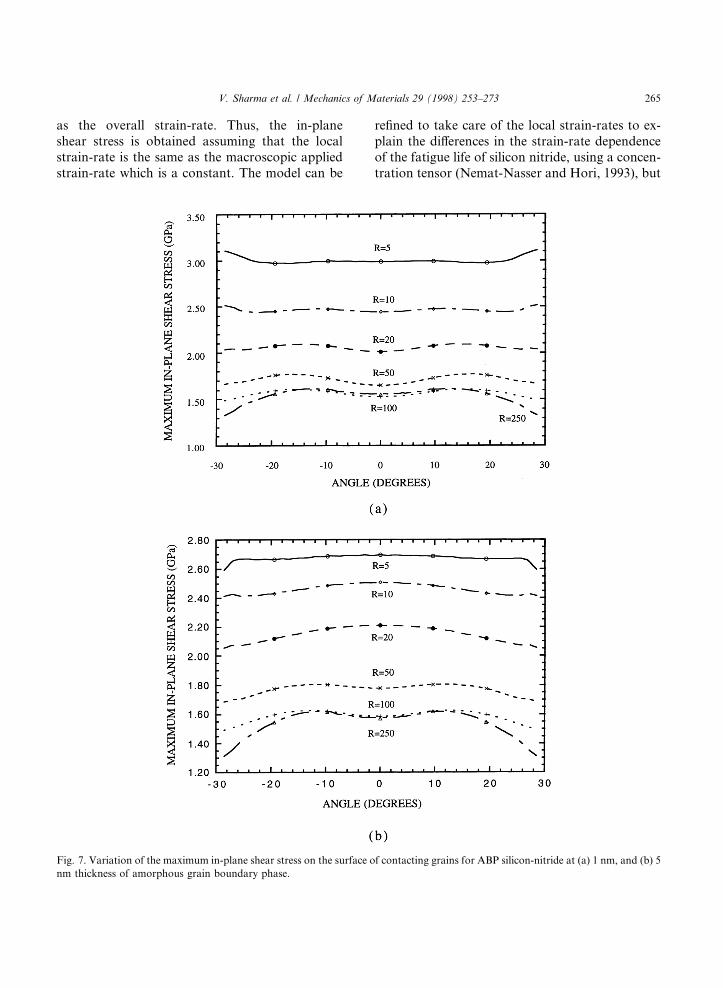
The e�ective stress in the intergranular layer, inthe vicinity of a contact point, was evaluated byassuming isotropic and linearly elastic silicon nit-ride grains and an elastic-perfectly plastic grainboundary phase. The e�ect of the yield stress onthe maximum in-plane shear stress was evaluatedfor elastic silicon nitride grains and the elastic-plastic grain boundary phase. Fig. 8 shows the ef-fect of changing the yield stress on the maximumin-plane shear stress for CBP silicon nitride. Forelastic silicon nitride grains and the elastic inter-granular phase (curve labeled elas, 346 fromFig. 7), the maximum e�ective stress in the inter-granular layer, in the vicinity of the contact region,was about 3 GPa. The maximum in-plane shear
stress decreases monotonically as the e�ective yieldstress is decreased. The decrease in the maximumin-plane shear stress is about 14% when the e�ec-tive yield stress decreases from 3 to 2 GPa. Thus,as the strain-rate (e�ective yield stress of the inter-granular layer) is increased, the maximum in-planeshear stress at the contact region increases, therebyincreasing the fatigue crack nucleation sites andthe growth of fatigue cracks. In other words, asthe strain-rate is increased, the fatigue life ofCBP silicon nitride decreases.
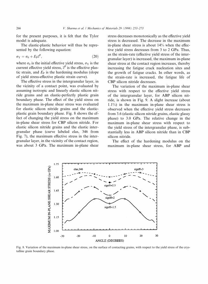
The variation of the maximum in-plane shearstress with respect to the e�ective yield stressof the intergranular layer, for ABP silicon nit-ride, is shown in Fig. 9. A slight increase (about1.1%) in the maximum in-plane shear stress isobserved when the e�ective yield stress decreasesfrom 3.6 (elastic silicon nitride grains, elastic glassyphase) to 3.0 GPa. The relative change in themaximum in-plane shear stress with respect tothe yield stress of the intergranular phase, is sub-stantially less in ABP silicon nitride than in CBPsilicon nitride.
The e�ect of the hardening modulus on themaximum in-plane shear stress, for ABP and
Fig. 8. Variation of the maximum in-plane shear stress, on the surface of contacting grains, with respect to the yield stress of the crys-
talline grain boundary phase.
266 V. Sharma et al. / Mechanics of Materials 29 (1998) 253±273
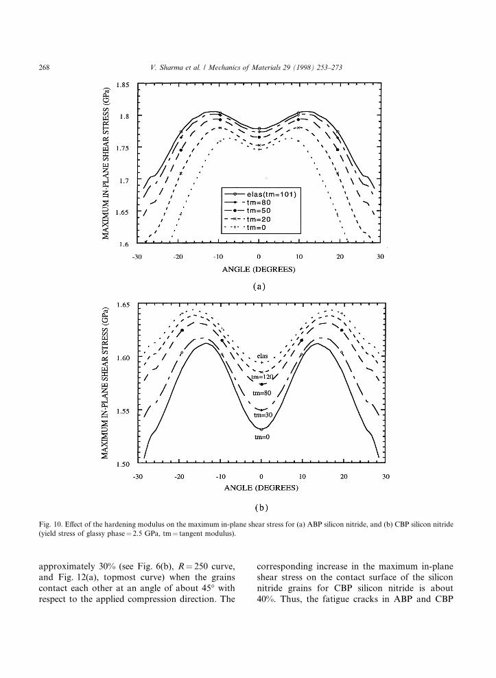
CBP silicon nitrides, is shown in Fig. 10(a) and(b), respectively. The e�ective yield stress of the in-tergranular phase was taken as 2.5 GPa. The hard-ening modulus of the crystalline phase was chosenas 0 (elastic-perfectly plastic phase), 30, 80, and120 GPa, whereas the hardening modulus of theglassy phase was chosen as 0 (elastic-perfectly plas-tic glassy phase), 20, 50, and 80 GPa. As thehardening modulus increases, the maximum in-plane shear stress increases. The increase in themaximum in-plane shear stress with respect tothe hardening modulus is relatively less in ABPsilicon nitride compared to that in CBP siliconnitride.
It was mentioned earlier that a plane strain ge-ometry of the repetitive cell is used to analyze thecontact problem. The preclusion of the out-of-plane movement of the repetitive cell, under planestrain geometry, results in a high lateral constraintwhich lowers the maximum in-plane shear stress.In reality, out-of-plane movement is allowed tosome extent. Thus, the actual values of the maxi-mum in-plane shear stress should be lower thanthose shown in Figs. 8 and 9, and 10.
To ®nd the change in the maximum in-planeshear stress when the contact between grains oc-
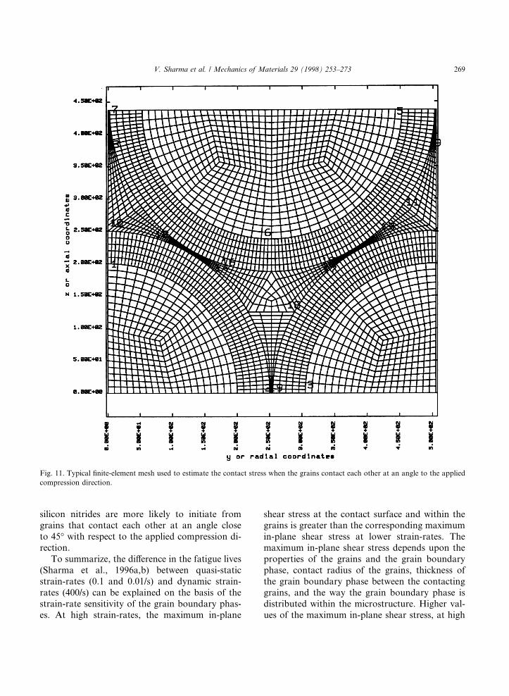
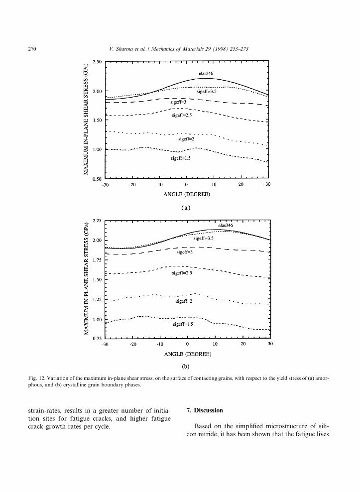
curs at an angle to the applied compression, the re-petitive unit cell (see Fig. 4) was modi®ed slightly.The diameter of the circular grains on the side ofthe cell was made equal to the diameter of thegrains at the top and bottom of the cell (250nm). The axial dimension of the repetitive cellwas increased to accommodate the grains on theside, whereas the radial dimension was kept con-stant at 505 nm. Fig. 11 shows the top half ofthe modi®ed repetitive cell used to ®nd the contactstress between the contacting grains. Fig. 12(a)and (b) show the variation of the maximum in-plane shear stress with respect to the yield stressof the intergranular layer, on the surface of thecontacting grain for ABP and CBP silicon nitrides,respectively, for a 5 nm thickness of the intergran-ular layer. Unlike in previous cases, the maximumin-plane shear stress is not symmetric about thecontact point. It can be observed from Figs. 8and 9, and 12(a) and (b) that the change in themaximum in-plane shear stress with respect tothe yield stress of the intergranular layer is at leastthree times greater for the modi®ed repetitive cell.The maximum in-plane shear stress on the surfaceof the contacting grains, for elastic grains and elas-tic glassy grain boundary phases, increases by
Fig. 9. Variation of the maximum in-plane shear stress, on the surface of contacting grains, with respect to the yield stress of the amor-
phous grain boundary phase.
V. Sharma et al. / Mechanics of Materials 29 (1998) 253±273 267
approximately 30% (see Fig. 6(b), R� 250 curve,and Fig. 12(a), topmost curve) when the grainscontact each other at an angle of about 45° withrespect to the applied compression direction. The
corresponding increase in the maximum in-planeshear stress on the contact surface of the siliconnitride grains for CBP silicon nitride is about40%. Thus, the fatigue cracks in ABP and CBP
Fig. 10. E�ect of the hardening modulus on the maximum in-plane shear stress for (a) ABP silicon nitride, and (b) CBP silicon nitride
(yield stress of glassy phase� 2.5 GPa, tm� tangent modulus).
268 V. Sharma et al. / Mechanics of Materials 29 (1998) 253±273
silicon nitrides are more likely to initiate fromgrains that contact each other at an angle closeto 45° with respect to the applied compression di-rection.
To summarize, the di�erence in the fatigue lives(Sharma et al., 1996a,b) between quasi-staticstrain-rates (0.1 and 0.01/s) and dynamic strain-rates (400/s) can be explained on the basis of thestrain-rate sensitivity of the grain boundary phas-es. At high strain-rates, the maximum in-plane
shear stress at the contact surface and within thegrains is greater than the corresponding maximumin-plane shear stress at lower strain-rates. Themaximum in-plane shear stress depends upon theproperties of the grains and the grain boundaryphase, contact radius of the grains, thickness ofthe grain boundary phase between the contactinggrains, and the way the grain boundary phase isdistributed within the microstructure. Higher val-ues of the maximum in-plane shear stress, at high
Fig. 11. Typical ®nite-element mesh used to estimate the contact stress when the grains contact each other at an angle to the applied
compression direction.
V. Sharma et al. / Mechanics of Materials 29 (1998) 253±273 269
strain-rates, results in a greater number of initia-tion sites for fatigue cracks, and higher fatiguecrack growth rates per cycle.
7. Discussion
Based on the simpli®ed microstructure of sili-con nitride, it has been shown that the fatigue lives
Fig. 12. Variation of the maximum in-plane shear stress, on the surface of contacting grains, with respect to the yield stress of (a) amor-
phous, and (b) crystalline grain boundary phases.
270 V. Sharma et al. / Mechanics of Materials 29 (1998) 253±273
of ABP and CBP silicon nitrides depend upon thefatigue frequency if the intergranular phase isstrain-rate sensitive. As mentioned earlier, the ac-tual microstructure of both materials is rathercomplicated, and it is not possible to model the ex-act microstructures of ABP and CBP silicon nit-rides. Thus, the model presented in thisinvestigation does not explain the observed di�er-ences in the behavior of ABP and CBP silicon nit-rides.
The explanation of the di�erences in the behav-ior of ABP and CBP silicon nitrides requires a bet-ter understanding of the contact stress as afunction of the loading rate. In addition to thecontact radius, the thickness and distribution ofthe intergranular layer, and the elastic propertiesof the grains and the grain boundary phase, thecontact stress between impinging silicon nitridegrains also depends upon the internal stresseswithin the material and the variation of the yieldstress and hardening parameter of the grain boun-dary phase as a function of strain-rate. The actualcontact stress between silicon nitride grains can behigher or lower in the ABP or CBP materials, de-pending upon the internal stress and strain-ratesensitivity of the boundary phase.
For similar internal stress and strain-rate sensi-tive behaviors of both materials, higher fatigue lifecan be observed for the material that experienceshigher contact stress due to the di�erences in thefatigue crack propagation rates. The propagationof fatigue cracks depends upon the strength ofthe boundary phase, the interfacial strength be-tween silicon nitride grains and the boundaryphase, etc. Thus, modeling of the di�erent behav-iors of ABP and CBP silicon nitrides is rather com-plex, as it requires detailed knowledge aboutsilicon nitride grains, the boundary phase, the in-ternal stresses, etc.
The change in the peak stress for two orders ofmagnitude di�erence in the fatigue life can be esti-mated and compared with the numerical results.Let us assume that the growth of microcracksper cycle is governed by the Paris equation (Pariset al., 1961) da=dN � A�DK�n. According to thisequation, the di�erence in the crack growth ratedepends upon the crack velocity parameter (n),and the di�erence between the maximum and the
minimum stress intensity factor (DK). The crackvelocity parameter has been obtained experimen-tally for di�erent types of silicon nitrides. Ko(1987) obtained a value of 25 for sintered siliconnitride (rotary bending fatigue), Matsuo et al.(1983) obtained a value of 55 and 63 for sinteredand hot-pressed silicon nitrides (under positivecut sinusoidal cycle), respectively, and Nikkilaand Mantyla (1989) observed values of 31 and 41for two di�erent types of sintered silicon nitridesand a value of 43 for hot-pressed silicon nitride(under tension-compression loading) as the crackvelocity parameter. If the crack velocity parameterfor ABP and CBP silicon nitrides is chosen as 40,then the crack growth rate decreases by two ordersof magnitude for every 9% decrease in the peakstress. The change in the maximum in-plane shearstress (see Figs. 8 and 9) on the surface of the con-tacting grains is of this order of magnitude. How-ever, away from the contact region, the change inthe stress components become negligible as thestrain-rate is changed. Based on this argument,the actual change in the peak stress to cause twoorders of magnitude di�erence in the fatigue lifeis more than 9%. On the other hand, the numberof cracks generated in ABP and CBP silicon nit-rides, per cycle, increases as the strain-rate is in-creased from 0.01 to 400/s. Consequently, thee�ective crack growth rate (crack growth rate as-suming the same number of microcracks) is greaterat 400/s compared to that at 0.01/s. Thus, the actu-al change in the peak stress for two orders of mag-nitude di�erence in the fatigue life is less than thepredicted change based on the Paris equation. Re-gardless of the process that dominates the e�ectivecrack growth rate, the actual change in the peakstress is not expected to deviate much from thepredicted change.
Based on the observation of Bridgeman and Si-mon (1953), the grain boundary phase was as-sumed to have strain-rate sensitive plasticity,whereas silicon nitride grains were assumed to beelastic. If one assumes silicon nitride grains to havestrain-rate sensitive plasticity and the grain boun-dary phase to be elastic, then it is observed that,compared to the change in the yield stress of sili-con nitride grains has a much more profound e�ecton the corresponding change in the maximum
V. Sharma et al. / Mechanics of Materials 29 (1998) 253±273 271
in-plane shear stress. This is likely due to highvolume fraction of silicon nitride grains (89%).
Finally, the hysteresis in the stress-axial straincurves for both materials at dynamic strain-rates(Sharma et al., 1996a,b) can be explained on the ba-sis of the energy dissipation processes occurringwithin the materials. The two dominant processesthat result in a loss of energy within the materialsare the generation and propagation of microcracks,and the plastic deformation of the grain boundaryphase. Since the volume fraction of the grain boun-dary phase is small (approximately 11%) and theplasticity of the intergranular phases is assumed tooccur in the vicinity of the contacting grains, theplasticity of the grain boundary phase does not con-sume much energy. At high strain-rates, the initia-tion of a large number of fatigue cracks and highercrack growth rates results in the loss of a largeamount of energy within the materials. Consequent-ly, the opening of the stress-axial strain curve is sig-ni®cant at dynamic strain-rates compared to that atthe quasi-static strain-rates.
8. Conclusions
The contact region between two silicon nitridegrains was identi®ed as the fatigue crack nucle-ation site in ABP and CBP silicon nitrides, at0.01 and 400/s strain-rates. The degradation ofthe dynamic fatigue life compared to the quasi-static fatigue life is explained on the basis of thestrain-rate sensitivity of the grain boundary phaseand/or silicon nitride grains, and the manner bywhich the forces are transmitted over the contactarea of the contacting grains. The microstructureof the materials was modeled as a periodic micro-structure and the contact stresses between adjacentsilicon nitride grains were calculated numerically.It was observed that, at low strain-rates, the grainboundary phase and/or silicon nitride grains yieldat a lower stress, thereby decreasing the contactstress, the average stress, and more importantly,the maximum shear stress in silicon nitride grains.This results in lower dislocation activity and lowercrack-growth rates, and consequently the fatiguelives of ABP and CBP silicon nitrides increase asthe strain-rate is decreased from 400 to 0.01/s.
Acknowledgements
This research was supported by a grant fromthe Army Research O�ce under contracts No.DAAL-03-86-K-0169 and DAAL-03-92-K-0002to UCSD. The computations reported in this pa-per were performed on a CRAY-C90 computerat the San Diego Supercomputer Center.
References
Ahn, C.C., Thomas, G., 1983. Microstructure and grain
boundary composition of hot-pressed silicon nitride
with yttria and alumina. J. Amer. Ceram. Soc. 66 (1), 14±
17.
Ashby, M.F., Hallam, S.D., 1986. The failure of brittle solids
containing small cracks under compressive stress states.
Acta. Meta. 34 (3), 497±510.
Bridgeman, P.W., Simon, I., 1953. E�ect of very high pressure
on glass. J. Appl. Phys. 24, 405±413.
Hallquist, J.O., 1983. MAZE ± An input generator for
DYNA2D and NIKE2D. University of California, Law-
rence Livermore National Laboratory, Rept. UCID - 19029.
Hallquist, J.O., 1986. NIKE2D: A vectorized implicit, ®nite
deformation, ®nite element code for analyzing the static and
dynamic response of 2-D solids with interactive rezoning
and graphics. University of California, Lawrence Livermore
National Laboratory, Rept. UCID-19677.
Hallquist, J.O., 1979. NIKE2D: An implicit, ®nite deformation.
Finite element code for analyzing the static and dynamic
response of two-dimensional solids. University of Califor-
nia, Lawrence Livermore National Laboratory, Rept.
UCRL-52678.
Hallquist, J.O., Levatin, J.L., 1985. ORION: An interactive
color post-processor for two dimensional ®nite element
codes. University of California, Lawrence Livermore Na-
tional Laboratory, Rept. UCRL-19310.
Horii, H., Nemat-Nasser, S., 1986. Brittle failure in compres-
sion: Splitting, faulting and brittle-ductile transition. Phil.
Trans. Roy. Soc. Lond. 319 (1986), 337±374.
Ko, H.N., 1987. Fatigue strength of sintered silicon nitride
under rotary bending. J. Mat. Sci. Lett. 6, 175±177.
Makishima, A., Mackenzie, J.D., 1975. Calculation of bulk
modulus, shear modulus and poisson's ratio of glass. J.
Non-Cryst. Solids 17, 147±157.
Makishima, A., Mackenzie, J.D., 1973. Direct calculation
of Young's modulus of glass. J. Non-Cryst. Solids 12, 35±
45.
Matsuo, Y., Hattori, Y., Katayama, Y., Fukuura, I., 1983.
Cyclic fatigue behavior of ceramics. In: Riley, F.L. (Ed.),
Progress in Nitrogen Ceramics, pp. 515±522.
Nemat-Nasser, S., Iwakuma, T., Hejazi, M., 1982. On com-
posites with periodic structure. Mechanics of Materials 7,
239±267.
272 V. Sharma et al. / Mechanics of Materials 29 (1998) 253±273
Micromechanics: Overall Properties of Heterogeneous Materi-
als. In: Achenbach, J.D., Budiansky, B., Lauwerier, H.A.,
Sa�man, P.G., Wijngaarden, L.V., Willis, J.R. (Eds.).
Elsevier, Amsterdam.
Nemat-Nasser, S., Yu, N., Hori, M., 1993. Bounds and
estimates of overall moduli of composites with periodic
microstructure. Mechanics of Materials 15, 163±181.
Nikkila, A.P., Mantyla, T.A., 1989. Cyclic fatigue of silicon
nitrides. Ceram. Eng. Sci. Proc. 10 (7), 646±656.
Paris, P.C., Gomez, M.P., Anderson, W.E., 1961. A rational
analytic theory of fatigue. The Trend in Engineering 13, 9±14.
Sharma, V., Nemat-Nasser, S., Vecchio, K.S., 1994. Dynamic
compression fatigue of hot-pressed silicon-nitride. Experi-
mental Mechanics 34, 315±332.
Sharma, V., 1994. Damage evolution in hot-pressed silicon
nitride under repeated dynamic and quasi-static compres-
sion loading, Doctoral Dissertation, University of Califor-
nia, San Diego.
Sharma, V., Nemat-Nasser, S., Vecchio, K.S., submitted.
Damage evolution in hot-pressed silicon nitride under
quasi-static compression fatigue. Materials Science and
Engineering, submitted.
Sharma, V., Nemat-Nasser, S., Vecchio, K.S., 1998. E�ect of
grain boundary phase on dynamic compression fatigue in
hot-pressed silicon nitride. J. Amer. Ceram. Soc., 81, 129-
139.
Taylor, G.I., 1934. The mechanism of plastic deformation of
crystals. Proc. Roy. Soc. A 145, 362±415.
V. Sharma et al. / Mechanics of Materials 29 (1998) 253±273 273