
Modeling of Frost Growth on Heat Exchanger Surfaces · Modeling of Frost Growth on Heat Exchanger...
9
The Modelica Association Modelica 2006, September 4 th – 5 th Modeling of Frost Growth on Heat Exchanger Surfaces Katrin Pr¨ olss, Gerhard Schmitz Hamburg University of Technology, Applied Thermodynamics Group Denickestr. 17, 21075 Hamburg Abstract A Modelica model to study the frost growth on paral- lel heat exchanger plates is developed. The coupled heat and mass transport phenomena involved in the process are described. A physical model which in- cludes the distributed densification of the frost layer is compared to a simple lumped model approach. The frost structure and thus the resulting properties such as density and thermal conductivity are found to have a strong influence on the model results. Empirical cor- relations for properties and transport coefficients are used in both models. The model describing the air- flow is taken from the Modelica Fluid library and ex- tended to handle condensation and freezing of water vapor. The Modelica.Media library provides the moist air property model. 1 Introduction Frost formation on heat exchanger surfaces in air cool- ing applications always occurs when the coil surface temperature drops below the freezing point of water and the dew point temperature of the air in contact with the cold surface. The main problems associated with frost growth are the decline in heat exchanger ef- ficiency resulting from an insulating effect of the frost layer and the rising pressure drop due to a decreas- ing hydraulic diameter of the flow channel, which in return increases the energy consumption of the fan. Usually a system operating under frosting conditions needs a defrost from time to time. In order to estimate the allowable frost growth period and the energy re- quired to melt down the frost layer, its stored amount of frozen water, thickness and thermal behavior have to be known. Several studies exist which try to for- mulate empirical approaches to predict the behavior of certain types of heat exchangers and surfaces, see e.g. [1], [2]. Hoffenbecker et al. [3] investigated defrost cycles with fin-and-tube heat exchangers and devel- oped a numerical model describing the process with given initial frost conditions. Over the past decades several attempts have been made to develop physical models of the transport phenomena which govern the general formation of a frost layer. In 1974 Sanders [4] already proposed a system of partial differential equa- tions describing the coupled heat and mass transport processes in his detailed study on frost structure and provided several simplified approaches. Le Gall et al. [5] and Tao et al. [6] developed more detailed mod- els and focused on the diffusion process of water va- por through the porous medium. But due to the com- plex structure and variety of ice crystal formation an entirely physical approach is hardly possible and the quality of the model still relies on some empirical cor- relations. The transport phenomena involved in the frost forma- tion process are sketched in figure 1. Warm moist air Figure 1: Transport phenomena in a porous frost layer passes a cold surface with a temperature below the freezing point of water and the dew point of the air. Heat transfer by forced convection occurs from the bulk flow to the cryosurface, driven by a temperature gradient. A concentration gradient causes a water va- por flux from the bulk flow to the frost surface where part of it freezes and adds to an increase of the layer while releasing latent heat. Part of the water vapor dif- 509 Modeling of Frost Growth on Heat Exchanger Surfaces
Transcript of Modeling of Frost Growth on Heat Exchanger Surfaces · Modeling of Frost Growth on Heat Exchanger...

The Modelica Association Modelica 2006, September 4th – 5th
Modeling of Frost Growth on Heat Exchanger Surfaces
Katrin Prolss, Gerhard SchmitzHamburg University of Technology, Applied Thermodynamics Group
Denickestr. 17, 21075 Hamburg
Abstract
A Modelica model to study the frost growth on paral-lel heat exchanger plates is developed. The coupledheat and mass transport phenomena involved in theprocess are described. A physical model which in-cludes the distributed densification of the frost layeris compared to a simple lumped model approach. Thefrost structure and thus the resulting properties such asdensity and thermal conductivity are found to have astrong influence on the model results. Empirical cor-relations for properties and transport coefficients areused in both models. The model describing the air-flow is taken from the Modelica Fluid library and ex-tended to handle condensation and freezing of watervapor. The Modelica.Media library provides the moistair property model.
1 Introduction
Frost formation on heat exchanger surfaces in air cool-ing applications always occurs when the coil surfacetemperature drops below the freezing point of waterand the dew point temperature of the air in contactwith the cold surface. The main problems associatedwith frost growth are the decline in heat exchanger ef-ficiency resulting from an insulating effect of the frostlayer and the rising pressure drop due to a decreas-ing hydraulic diameter of the flow channel, which inreturn increases the energy consumption of the fan.Usually a system operating under frosting conditionsneeds a defrost from time to time. In order to estimatethe allowable frost growth period and the energy re-quired to melt down the frost layer, its stored amountof frozen water, thickness and thermal behavior haveto be known. Several studies exist which try to for-mulate empirical approaches to predict the behavior ofcertain types of heat exchangers and surfaces, see e.g.[1], [2]. Hoffenbecker et al. [3] investigated defrostcycles with fin-and-tube heat exchangers and devel-oped a numerical model describing the process with
given initial frost conditions. Over the past decadesseveral attempts have been made to develop physicalmodels of the transport phenomena which govern thegeneral formation of a frost layer. In 1974 Sanders [4]already proposed a system of partial differential equa-tions describing the coupled heat and mass transportprocesses in his detailed study on frost structure andprovided several simplified approaches. Le Gall et al.[5] and Tao et al. [6] developed more detailed mod-els and focused on the diffusion process of water va-por through the porous medium. But due to the com-plex structure and variety of ice crystal formation anentirely physical approach is hardly possible and thequality of the model still relies on some empirical cor-relations.The transport phenomena involved in the frost forma-tion process are sketched in figure 1. Warm moist air
Figure 1: Transport phenomena in a porous frost layer
passes a cold surface with a temperature below thefreezing point of water and the dew point of the air.Heat transfer by forced convection occurs from thebulk flow to the cryosurface, driven by a temperaturegradient. A concentration gradient causes a water va-por flux from the bulk flow to the frost surface wherepart of it freezes and adds to an increase of the layerwhile releasing latent heat. Part of the water vapor dif-
509
Modeling of Frost Growth on Heat Exchanger Surfaces
The Modelica Association Modelica 2006, September 4th – 5th
fuses into the frost layer leading to a densification ofthe structure. The sum of sensible and latent heat istransported to the cold wall interface by thermal con-duction.
2 Modeling the frost formation pro-cess
2.1 Frost formation types
During the process of frost deposition on a cold sur-face several stages of frost formation may be distin-guished. Hayashi et al. [7] found three periods de-scribing the formation of a frost layer:
• the crystal growth period
• the frost layer growth period
• the frost layer full growth period
The first corresponds to the first formation of ice crys-tals on the cryosurface, which basically form paral-lel columns or needles growing in one dimension. Inthe frost layer growth period they start interbranchingwhich leads to a meshed more uniform frost layer. Thesurface temperature of the frost gradually increaseswith increased frost thickness due to a rising ther-mal resistance. When the triple point temperature isreached the frost surface begins to melt, water soaksinto the frost and decreases its thermal resistance,which again leads to additional frost deposition andunder continuous melting and freezing eventually to adense and tight layer. This stage is referred to as thefull growth period. In the following model only thefrost layer growth period will be considered.Hayashi et al. classified four types of frost crystalstructure with respect to the cryosurface temperatureand the water concentration difference between bulkflow and surface. Generally, higher cryosurface tem-peratures and lower concentration gradients lead todenser and more homogeneous frost layers. In thesame study the frost type was found to have a stronginfluence on frost properties like density and thermalconductivity.
2.2 Energy and mass balances
Heat and mass transport through the ice layer are con-sidered one-dimensional, because a prevailing temper-ature gradient and a frost dimension very small com-pared to the other two is assumed perpendicular to walland air flow. Further assumptions are that temperature
variations of moist air and ice properties are neglected,the total gas phase pressure is constant throughout theporous medium, radiation effects are neglected andthermodynamic equilibrium prevails between ice andair in the pores.The water mass balance over the ice phase of the frostlayer can be written as the change of accumulated iceand water vapor equal to the spatial change of the dif-fusive vapor transport rate [5].
¶(ra ea)
¶t+
¶(rv,sat eb)
¶t= −
¶mv
¶x(1)
where mv is the water vapor mass flow per unit areaand ra is the density of ice. The moist air in the frostpores is always assumed to be saturated with vapor,the vapor density rv,sat in the gas phase is thereforedetermined by the local temperature applying the idealgas law and the saturation pressure curve of water. eaand eb are the ice and moist air volume fractions, re-spectively. The driving potential for the diffusive wa-ter transport is the gradient of vapor partial pressure inthe gas phase pv, the resulting vapor flux for moleculardiffusion is then obtained from [8]
mv = −Deff
RvT¶pv
¶x(2)
with Deff as the effective coefficient of diffusion andRv as the ideal gas constant of water, T is the localtemperature.Equation 1 may then be transformed into
¶ rv,sat
¶T(1− ea)
¶ T¶t
+(ra −rv,sat)¶ ea
¶t
=¶¶x
(
Deff
RvT¶pv
¶x
)
. (3)
The energy balance over the frost element is
¶u∗f¶t
=¶¶x
(
lf¶T¶x
)
−¶mv
¶xDhsv (4)
The first term on the right handside of equation 4 cor-responds to the conductive heat flow, the second rep-resents the enthalpy tranport associated with the dif-fusive vapor flux with Dhsv as the heat of fusion. Thefrost energy per unit volume u∗ is given by
u∗f = cf rf T +(1− ea) rv,sat Dhsv (5)
where cf is the specific heat capacity of frost, rf is thefrost density and T is the local temperature.A simplifying assumption to the problem is the neglec-tion of water vapor diffusing into the frost layer. The
510
K. Proelss, G. Schmitz
The Modelica Association Modelica 2006, September 4th – 5th
energy balance then reduces to the basic formulationof unsteady heat conduction [8].
¶(rf cf T )
¶ t=
¶¶x
(
lf¶ T¶x
)
(6)
2.3 Boundary conditions
2.3.1 Wall
The boundary conditions at the wall side of the frostlayer are:
T (x = xw) = Tw
mv(x = xw) = 0 . (7)
The index w denotes the position at the wall interface,mv is the water vapor flux.
2.3.2 Airside heat and mass transfer
The heat transferred from the airflow to the frost sur-face is expressed as the sum of sensible and latent heatflows.
qsens + qlat = lf(xs)¶Ts
¶x(8)
a(Tb −Ts)+ Dhsv(mt − mv,s) = lf(xs)¶Ts
¶x(9)
where a is the coefficient of heat transfer, Tb is thebulk air temperature and the index s denotes surfaceproperties. mt and mv,s are the total vapor flux fromthe air to the frost layer and the vapor flux into the frostlayer, respectively. They may be determined from
mv,s = mv(x = xs) =
(
Deff
RvT
)
s
¶pv,s
¶x(10)
mt = rab(Xb −Xs) (11)
where b is the mass transfer coefficient in m/s andX is the absolute humidity in in the bulk flow and atthe frost surface, respectively and ra is the air density.Substracting the two fluxes yields the frost depositionrate at the frost surface.
rf,s¶xs
¶t= mt − mv,s (12)
The surface density may be calculated from an empir-ical correlation by Hayashi et al. [9]
rf,s = 650 e0.227(Ts−273.15) (13)
where Ts is the surface temperature in K. In [6] a zerogradient for the ice volume fraction is assumed at thesurface.
¶ea,s
¶x= 0; (14)
If a simplified model is used that does not account forwater diffusion into the frost, mv,s is set to zero andthe entire water mass flow towards the frost surfaceis assumed to contribute to the increase of frost layerheight.Empirical correlations are used to determine the trans-port coefficients. In the literature the Chilton-Colburnanalogy between heat and mass transfer seems to bewidely accepted also under frosting conditions [2][11]. It relates the mass transfer coefficient b to theheat transfer coefficient a using the Lewis number Le:
b =a
cp raLe2/3 (15)
ra ist the moist air density and cp is the specific heatcapacity. According to [2] the heat transfer coeffi-cients are normally higher under frosting conditionscompared to a smooth surface due to an increased sur-face roughness. However, it is unclear if the reductionof the hydraulic diameter also adds to this reported in-crease. The following correlation suggested by [2] forair flow between parallel plates for Reynolds numberranging from 6000 to 50000 was used:
Nuf = 0.034 Re0.8 (16)
where the Reynolds number is based on the hydraulicdiameter of the parallel plate channel.
2.4 Frost properties
As described above the prediction of frost layer thick-ness and its thermal behavior largely depends on frostproperties such as density, thermal conductivity andthe effective diffusion coefficient of water vapor inthe air filled porous medium. The diversity of pos-sible frost structures as indicated in section 2.1 clearlyshows that an accurate determination of those proper-ties for a wide range of operating conditions and heatexchanger types may be a difficult task. The widerange of empirical correlations and theoretical modelsthat have been established sometimes are mostly ap-plicable only in a very limited operating range. A lit-erature review of empirical correlations for frost prop-erties and frost layer thickness can be found e.g. in[2].
2.4.1 Thermal conductivity
The significant thermal resistance added to the heat ex-changer wall by the growing frost layer results fromthe rather low thermal conductivity of the ice-air com-posite. The air in the pores largely contributes to the
511
Modeling of Frost Growth on Heat Exchanger Surfaces
The Modelica Association Modelica 2006, September 4th – 5th
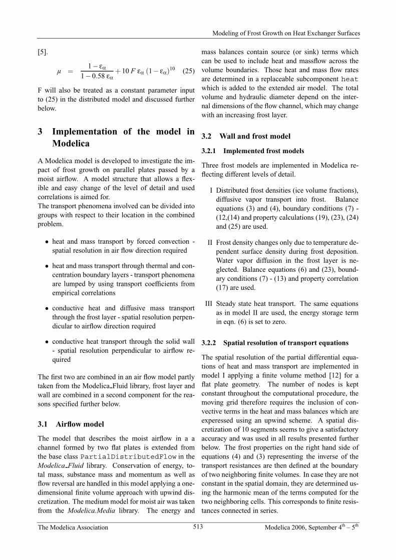
insulating effect. Also the structure and orientation ofthe ice crystals influence the material property. Thereis an agreement in the literature that thermal conduc-tivity is a strong function of frost density with only aweak dependence on temperature. An empirical cor-relation based on the frost layer density from [10] isused for the proposed models:
lf = 0.02442+ 7.214 ·10−4rf + 1.1797 ·10−6r2f . (17)
Another correlation suggested by [2] is
lf = 1.202 ·10−3 r0.963f (18)
More theoretical approaches take into account the(generally assumed) frost structure and sometimeseven the surface roughness as in [11]. All correla-tions are found between the two ideal assumptions ofice crystals parallel and perpendicular to the prevailingdirection of heat transport. The first orientation corre-sponds to thermal resistances in series, the second to aparallel arrangement. Their conductivities can be ob-tained as follows
1/lper = (1− ea)/la + ea/la (perpendicular)
lpar = (1− ea)la + eala (parallel)
(19)
where la and la are the thermal conductivities of airand ice, respectively. A comparison of this approachwith eq. (17) and (18) is given in figure 2. It shows thatthe presented empirical correlations are found withinthe two ideal structure models, but still reveal signif-icant deviations in one to another. It is expected thatdifferences in frost structure which cannot be relatedto density or ice volume fraction alone that are causedby variable frost growth conditions and aging effectsalso play an important role.
2.4.2 Density and specific heat capacity
The way to determine the frost density depends on theassumptions made for the vapor transport in section2.2. If equation 1 is used, the density distribution inthe frost layer can be determined from the ice volumefraction ea
rf = eara +(1− ea)(ra + rv) (20)
≈ eara (21)
The volumetric heat capacity may be computed in asimilar way and with neglection of the gas phase im-pact reduces to:
rfcf ≈ earaca (22)
0 100 200 300 400 500 600 700 8000
0.5
1
1.5
2
Density r, kg/m3
The
rmal
con
duct
ivity
l, W
/mK
Yonko et al.Parallel crystalsPerpendicular crystalsSanders
Figure 2: Thermal conductivity vs. frost density forthe empirical correlation by Yonko et al. (17), the cor-relation by Sanders (18) as well as perpendicular andparallel ice crystal orientation, respectively.
If the frost layer is assumed to have a uniform den-sity over the entire frost height and equation 6 is used,the average frost density rf is computed from a massbalance over the total frost layer,
¶(rfdf)
¶t= mt (23)
with mt from eq. (10) and the frost thickness df.
2.4.3 Coefficient of diffusion
Following from (10) the frost density largely dependson the water vapor that diffuses into the frost layer.The effective diffusion coefficient Deff in (3) accountsfor several complex mechanisms. Those involve be-sides molecular diffusion the tortuosity of the porousfrost structure, the variation of pore diameters, phasetransitions and others. The effective diffusion coeffi-cient may be expressed in terms of the binary diffusioncoefficient DAB
Deff = µDAB (24)
Several works focus on the determination of the µ fac-tor with significantly different results. The first modelsdealing with effective diffusion factors for frost alwaysassumed lower values than those for molecular diffu-sion (µ ≤1), others including Tao et al. in [6] reportvalues several times larger. Le Gall et al. propose acorrelation that combines both approaches and try todetermine the factor F in the following equation em-pirically with respect to selected boundary conditions
512
K. Proelss, G. Schmitz
The Modelica Association Modelica 2006, September 4th – 5th
[5].
µ =1− ea
1−0.58 ea+ 10 F ea (1− ea)10 (25)
F will also be treated as a constant parameter inputto (25) in the distributed model and discussed furtherbelow.
3 Implementation of the model inModelica
A Modelica model is developed to investigate the im-pact of frost growth on parallel plates passed by amoist airflow. A model structure that allows a flex-ible and easy change of the level of detail and usedcorrelations is aimed for.The transport phenomena involved can be divided intogroups with respect to their location in the combinedproblem.
• heat and mass transport by forced convection -spatial resolution in air flow direction required
• heat and mass transport through thermal and con-centration boundary layers - transport phenomenaare lumped by using transport coefficients fromempirical correlations
• conductive heat and diffusive mass transportthrough the frost layer - spatial resolution perpen-dicular to airflow direction required
• conductive heat transport through the solid wall- spatial resolution perpendicular to airflow re-quired
The first two are combined in an air flow model partlytaken from the Modelica Fluid library, frost layer andwall are combined in a second component for the rea-sons specified further below.
3.1 Airflow model
The model that describes the moist airflow in a achannel formed by two flat plates is extended fromthe base class PartialDistributedFlow in theModelica Fluid library. Conservation of energy, to-tal mass, substance mass and momentum as well asflow reversal are handled in this model applying a one-dimensional finite volume approach with upwind dis-cretization. The medium model for moist air was takenfrom the Modelica.Media library. The energy and
mass balances contain source (or sink) terms whichcan be used to include heat and massflow across thevolume boundaries. Those heat and mass flow ratesare determined in a replaceable subcomponent heatwhich is added to the extended air model. The totalvolume and hydraulic diameter depend on the inter-nal dimensions of the flow channel, which may changewith an increasing frost layer.
3.2 Wall and frost model
3.2.1 Implemented frost models
Three frost models are implemented in Modelica re-flecting different levels of detail.
I Distributed frost densities (ice volume fractions),diffusive vapor transport into frost. Balanceequations (3) and (4), boundary conditions (7) -(12,(14) and property calculations (19), (23), (24)and (25) are used.
II Frost density changes only due to temperature de-pendent surface density during frost deposition.Water vapor diffusion in the frost layer is ne-glected. Balance equations (6) and (23), bound-ary conditions (7) - (13) and property correlation(17) are used.
III Steady state heat transport. The same equationsas in model II are used, the energy storage termin eqn. (6) is set to zero.
3.2.2 Spatial resolution of transport equations
The spatial resolution of the partial differential equa-tions of heat and mass transport are implemented inmodel I applying a finite volume method [12] for aflat plate geometry. The number of nodes is keptconstant throughout the computational procedure, themoving grid therefore requires the inclusion of con-vective terms in the heat and mass balances which areexperessed using an upwind scheme. A spatial dis-cretization of 10 segments seems to give a satisfactoryaccuracy and was used in all results presented furtherbelow. The frost properties on the right hand side ofequations (4) and (3) representing the inverse of thetransport resistances are then defined at the boundaryof two neighboring finite volumes. In case they are notconstant in the spatial domain, they are determined us-ing the harmonic mean of the terms computed for thetwo neighboring cells. This corresponds to finite resis-tances connected in series.
513
Modeling of Frost Growth on Heat Exchanger Surfaces

The Modelica Association Modelica 2006, September 4th – 5th
Combining wall and frost layer in one component isadvantageous if the model should also be capable ofsimulating situations, when no frost layer is presentdue to a surface temperature higher than the triple orthe dew point. In this case the proposed equation sys-tem would become singular. Including the thermal re-sistance of the frost in the energy balance of the firstwall element until a certain frost thickness is reachedmakes it possible to determine the onset of frost for-mation by boundary conditions. The internal temper-atures are set to constant during this period and arereinitialized using the reinit operator as soon as athreshold value for the frost layer thickness is reached.A linear distribution of the difference between walland surface temperatures is used as start values. Thisapproach simply neglects the energy storage capacityof the frost layer in the initial growth period. The frostporosity also remains constant during this time. Theintial frost density is assumed to be rf,0 = 25 kg/m3 assuggested by [5].Both, wall and frost layer are also discretized in airflow direction without any interdependence of neigh-boring cells in this dimension.
3.3 Air - frost/wall interface
When the surface temperature is above the triplepoint and below the dew point of the air flow, watercondenses at the cold surface and is assumed toleave the system immediately. The liquid watervolume is therefore not considered. The model doesnot include situations of water condensation on apresent frost surface. The liquid would soak into theporous medium, its distribution would be very hardto predict. The connector variables required to com-bine the two components, airflow and frosted wall, are:
connector FrostPort
SI.HeatFlowRate Q flow "Sensible heatflow";SI.Temperature T "Surface temperature";SI.MassFlowRate m flow "Water mass flowrate (condensing or freezing)";SI.MassFraction xs "Saturated absolutehumidity at surface";SI.EnthalpyFlowRate H flow "Latent heatflow rate";SI.SpecificEnthalpy h gas "Specificenthalpy of vapor in bulk flow";SI.Velocity xf flow "Frost layer growthrate";SI.Length x f "Frost layer thickness";
end FrostPort;
The frost layer model versions I-III are organized asreplaceable components in the combined aiflow/wallmodel. They extend from a base class which containsthe parts all versions have in common, like e.g. the in-terface and some boundary conditions. All frost prop-erty correlations are written as functions.
4 Results and Discussion
4.1 Lumped frost layer model
Figure 3 shows the average values for frost thickness,frost density and surface temperature with respect totime and different air inlet velocities for model I. Adiscretization of 8 segments was chosen for the air-flow dimension. If the timescale of frost growth isof primary interest the steady state model (model III)gives results similar to model II and even on a shortertimescale the heat capacity of the frost layer may benegligible. However, introducing additional numericalstates may be advantageous in a more complex appli-cation to break down systems of nonlinear equations.
0 50 100 150 200 250 3000
2
4
6
d f, mm
0 50 100 150 200 250 3000
200
400
600
r f, kg/
m3
0 50 100 150 200 250 300260
265
270
275
Ts, K
t, min
cair
=1 m/s cair
= 3 m/s cair
= 6 m/s
Figure 3: Frost thickness df, mean frost density rf andsurface temperature Ts at different air inlet velocities.Tb=293K, Achannel,0 = 40cm2, Tw=263K, jair=42 %.
An increasing air flow rate leads to a higher frost de-position rate due to an increased heat and mass trans-fer. This creates a higher thermal resistance leadingto a greater surface temperature. At the same time thedensity of the frost layer increases with a rising sur-
514
K. Proelss, G. Schmitz
The Modelica Association Modelica 2006, September 4th – 5th
face temperature according to the used correlation forthe surface density (eq. 13) which in turn reduces thethermal resistance of the total frost layer. The totalthermal resistance responsible for the thermal behav-ior of the frosted heat exchanger surface is therefore aresult of the counteracting effects of densification andfrost growth.
0 20 40 60 80 100 120 140260
265
270
275
Ts
inK
0 20 40 60 80 100 120 1400
50
100
150
200
ρ fin
kg/m
3
0 20 40 60 80 100 120 1400
1
2
3
4
δ fin
mm
t in min
F = −2 F = 1 F = 6 emp. corr.
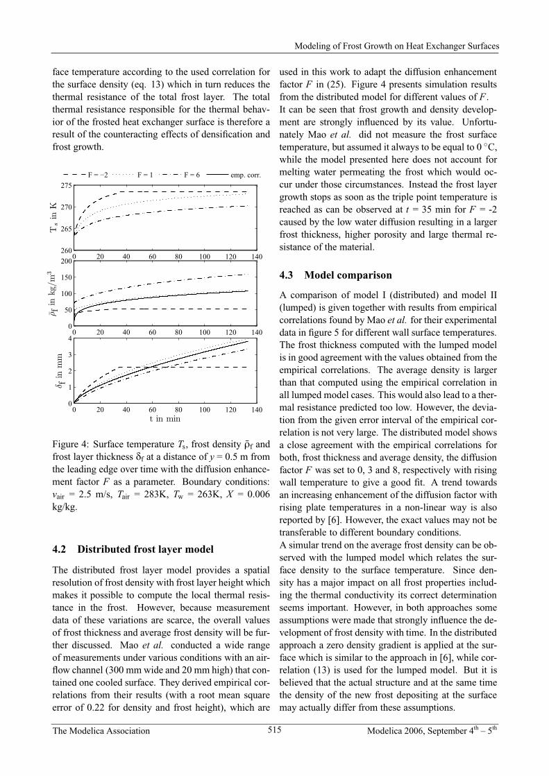
Figure 4: Surface temperature Ts, frost density rf andfrost layer thickness df at a distance of y = 0.5 m fromthe leading edge over time with the diffusion enhance-ment factor F as a parameter. Boundary conditions:vair = 2.5 m/s, Tair = 283K, Tw = 263K, X = 0.006kg/kg.
4.2 Distributed frost layer model
The distributed frost layer model provides a spatialresolution of frost density with frost layer height whichmakes it possible to compute the local thermal resis-tance in the frost. However, because measurementdata of these variations are scarce, the overall valuesof frost thickness and average frost density will be fur-ther discussed. Mao et al. conducted a wide rangeof measurements under various conditions with an air-flow channel (300 mm wide and 20 mm high) that con-tained one cooled surface. They derived empirical cor-relations from their results (with a root mean squareerror of 0.22 for density and frost height), which are
used in this work to adapt the diffusion enhancementfactor F in (25). Figure 4 presents simulation resultsfrom the distributed model for different values of F .It can be seen that frost growth and density develop-ment are strongly influenced by its value. Unfortu-nately Mao et al. did not measure the frost surfacetemperature, but assumed it always to be equal to 0 ◦C,while the model presented here does not account formelting water permeating the frost which would oc-cur under those circumstances. Instead the frost layergrowth stops as soon as the triple point temperature isreached as can be observed at t = 35 min for F = -2caused by the low water diffusion resulting in a largerfrost thickness, higher porosity and large thermal re-sistance of the material.
4.3 Model comparison
A comparison of model I (distributed) and model II(lumped) is given together with results from empiricalcorrelations found by Mao et al. for their experimentaldata in figure 5 for different wall surface temperatures.The frost thickness computed with the lumped modelis in good agreement with the values obtained from theempirical correlations. The average density is largerthan that computed using the empirical correlation inall lumped model cases. This would also lead to a ther-mal resistance predicted too low. However, the devia-tion from the given error interval of the empirical cor-relation is not very large. The distributed model showsa close agreement with the empirical correlations forboth, frost thickness and average density, the diffusionfactor F was set to 0, 3 and 8, respectively with risingwall temperature to give a good fit. A trend towardsan increasing enhancement of the diffusion factor withrising plate temperatures in a non-linear way is alsoreported by [6]. However, the exact values may not betransferable to different boundary conditions.A simular trend on the average frost density can be ob-served with the lumped model which relates the sur-face density to the surface temperature. Since den-sity has a major impact on all frost properties includ-ing the thermal conductivity its correct determinationseems important. However, in both approaches someassumptions were made that strongly influence the de-velopment of frost density with time. In the distributedapproach a zero density gradient is applied at the sur-face which is similar to the approach in [6], while cor-relation (13) is used for the lumped model. But it isbelieved that the actual structure and at the same timethe density of the new frost depositing at the surfacemay actually differ from these assumptions.
515
Modeling of Frost Growth on Heat Exchanger Surfaces

The Modelica Association Modelica 2006, September 4th – 5th
0 20 40 60 80 100 1200
0.5
1
1.5
2
δ fin
mm
0 20 40 60 80 100 1200
1
2
3
δ fin
mm
0 20 40 60 80 100 1200
1
2
3
4
t in min
δ fin
mm
distrib. m. lumped m. emp. corr.
T = 268 K
T = 263 K
T = 258 K
0 20 40 60 80 100 1200
100
200
300
ρ fin
kg/
m3
0 20 40 60 80 100 1200
50
100
150
200
ρf
inkg/m
3
0 20 40 60 80 100 1200
50
100
150
200
t in min
ρ fin
kg/
m3
distrib. m. lumped m. emp. corr.
T = 258 K
T = 263 K
T = 268 K
Figure 5: Frost layer thickness df and average frost density rfover time for the lumped and the distributed modeland an empirical correlation from [13]. Boundary conditions: vair = 2.5 m/s, Tair = 291 K, X = 0.006 kg/kg, y =0.5 m.
5 Conclusion
Resolving heat and mass transport phenomena in thespatial domain of the frost layer as it is done in modelI gives only higher accuracy in predicting frost growthand average density if information on the diffusion en-hancement factor F is present. The simple lumpedapproach (model II) is suitable to predict trends offrost formation with respect to variable boundary con-ditions, such as air and wall temperature, humidityand air velocity. A surprisingly good agreement is ob-tained for the predicted frost thickness when comparedto an empirical correlation. More accurate absolutevalues of density and thermal resistance with regard tooperating time may perhaps be obtained with a refine-ment of the model in terms of densification of the frostlayer with time and surface density of the deposit. Inaddition more empirical data is required, especially interms of the frost surface temperature, to validate themodel in a wide operating range.
Modeling the frost formation process correctly pro-vides information on the amount of frost and its icefraction at the start of the defrost process, which givesan idea of the minimum energy required for a completedefrost. Further work is needed to describe the defrost
process with time depending on the chosen strategy.The most common method of heating the solid wallmaterial using hot gas or electrical current poses theproblem of predicting the detachment of the frost layerfrom the wall and the associated heat transport throughgaps filled with liquid water or air. In addition, heattransfer to the surrounding air by natural convectionmust be taken into account if the air supply is stoppedduring this period.
References
[1] Xia, Y., Hrnjak, P. S. and Jacobi A. M, Air-sidethermal hydraulic performance of louvered-fin,flat-tube heat exchangers with sequential frost-growth cycles. ASHRAE Transactions, 2005,111, 487-495.
[2] O’Neal, D. L. and Tree D. R., A review of frostformation in simple geometries. ASHRAE Trans-actions, 1992, 98(Part 2), 65-78.
[3] Hoffenbecker, N., Klein, S.A. and Reindl, D.T.,Hot gas defrost model development and vali-dation. International Journal of Refrigeration,2005, 28, 605-615.
516
K. Proelss, G. Schmitz
The Modelica Association Modelica 2006, September 4th – 5th
[4] Sanders, C. T., Frost Formation: The influence
of frost formation and defrosting on the perfor-mance of air coolers. PhD thesis, Delft Univer-sity of Technology, Delft, 1974.
[5] Le Gall, R., Grillot, J. M. and Jallut, C., Mod-elling of frost growth and densification. Interna-tional Journal of Heat and Mass Transfer, 1997,40, 3177-3187.
[6] Tao, Y. X., Besant, R., W. and Rezkallah, K. S. Amathematical model for predicting the densifica-tion and growth of frost on a flat plate. Interna-tional Journal of Heat and Mass Transfer, 1993,36, 353-363.
[7] Hayashi Y., Aoki, A., Adachi, S. and Hori, K.,Study of frost properties correlating with frostformation types. Jornal of Heat Transfer, 1977,99, 239-245.
[8] Baehr, H. D., Stephan, K., Heat and Mass Trans-fer. 2nd Ed., Springer Verlag, Berlin, 2006.
[9] Hayashi Y., Aoki, A. and Yuhara, H., Studyof frost formation based on a theoretical modelof the frost layer. Heat Transfer - Japanese Re-search, 1977, 6, 79-94.
[10] Yonko, J. D. and Sepsy, C. F., An investigation ofthe thermal conductivity of frost while formingon a flat horizontal plate. ASHRAE Transactions,1967, 73, 1.1-1.11.
[11] Yun, R., Kim, Y. and Min, M., Modeling of frostgrowth and frost properties with airflow over aflat plate. International Journal of Refrigeration,2002, 25, 362-371.
[12] Patankar, S. V., Numerical Heat Transfer andFluid Flow. Hemisphere Publ. Co., New York,1980.
[13] Mao, Y., Besant, R.W., Rezkalla, K.S., Measure-ment and correlations of frost properties withairflowover a flat plate. ASHRAE Transactions,1992, 1, 65-78.
516.1
Modeling of Frost Growth on Heat Exchanger Surfaces