Modeling of Electrochemical Cells: Proton Exchange...
31
Modeling of Electrochemical Cells: Proton Exchange Membrane Fuel Cells HYD7007 - 01 HYD7007 01 Dept. of Chemical & Biomolecular Engineering Yonsei University Spring, 2011 Prof David Keffer Prof. David Keffer [email protected]
Transcript of Modeling of Electrochemical Cells: Proton Exchange...

Modeling of Electrochemical Cells:Proton Exchange Membrane Fuel Cells
HYD7007 - 01HYD7007 01
Dept. of Chemical & Biomolecular EngineeringYonsei Universityy
Spring, 2011
Prof David KefferProf. David [email protected]

Course Information
Class Meeting Location and Times● GS Caltex building, 1st floor seminar room ● Wednesday 6:00 PM – 9:00 PM
Course Website● http://utkstair org/clausius/docs/fuelcells/index html● http://utkstair.org/clausius/docs/fuelcells/index.html
Instructor Information● Office YERC 174B● Office YERC 174B ● Office telephone: 2123-5748● email: [email protected]

Course Objective
Objective
The objective of this portion of the course is to understand the molecular-level structure and transport processes of Proton Exchange Membranes (PEM) fuel cells.
Organization and Scheduling
The course is organized into four parts:● Structure (May 11, 2011)● Water & Charge Transport (May 18 2011)● Water & Charge Transport (May 18, 2011)● Membrane Composition (May 25, 2011)● Polymer Dynamics (June 8, 2011)

Course Grades
Overall Course Grades● The total course grade is an average of the three grades for each
instructor.
Course Grade for this Portion ● Attendance: 20%● Homework Assignments: 30%● Homework Assignments: 30%● Final Exam: 50%
Homework Assignmentsi t 1 A i d M 11 2011 D M 18 2011 b i i f l● assignment 1. Assigned: May 11, 2011. Due: May 18, 2011, beginning of class.
● assignment 2. Assigned: May 18, 2011. Due: May 25, 2011, beginning of class. ● assignment 3. Assigned: May 25, 2011. Due: June 8, 2011, beginning of class.
Final Examination● Covers only this final third of the class● date, time and location: To be determined.

h i l i l l l l d t i l d l
Instructor: Prof. Keffer
Slide on experiment
chemical engineer, molecular-level process and materials modeler
Slide on experimentMinneapolis, MNUniversity of MNPh.D. 1996
Washington, DCNaval Res. Lab
SeoulYonsei Univ.Visiting Prof. 2010 2011
Kansas City, MO
Naval Res. LabPostdoc 1996-7
2010-2011
Knoxville, TNUniversity of TNAsst. Prof. 1998Assoc Prof 2004
Gainesville, FLUniversity of FLB S 1992
Assoc. Prof. 2004Prof. 2009
B.S. 1992

Modeling of Electrochemical Cells:Proton Exchange Membrane Fuel CellsProton Exchange Membrane Fuel Cells
HYD7007 – 01
Lecture 01. Overview of PEM Fuel Cell Structure
Dept. of Chemical & Biomolecular EngineeringYonsei University
Spring, 2011
Prof. David [email protected]

Lecture Outline
● Motivation● Macroscopic Structure of Fuel Cells● Structure and Properties of Nafion● Examination of Macroscopic Models
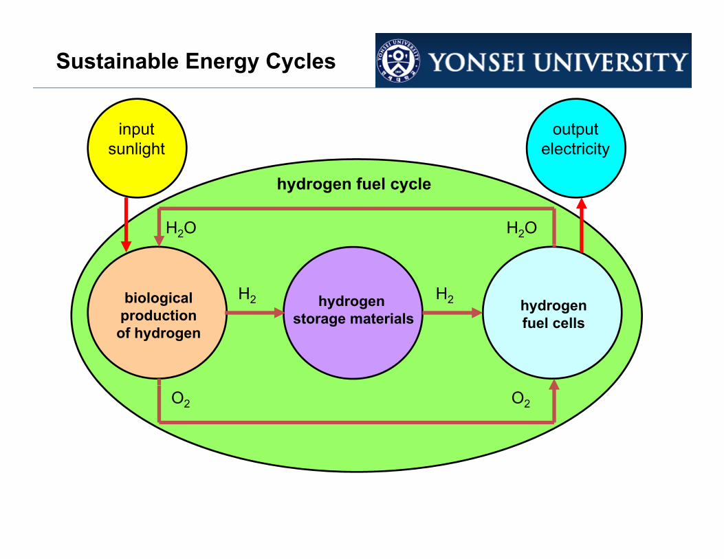
Sustainable Energy Cycles
inputsunlight
outputelectricity
H2OH2O
hydrogen fuel cycle
H2biologicalproduction hydrogen
H2hydrogen t t i lproduction
of hydrogen fuel cellsstorage materials
O2 O2

Sustainable Energy Cycles
H2 production H2 storage H2 conversion
H O Ph t l i i Al Materials discovery of novel nanoporous adsorbents with high capacity and fast
Understanding structure-property relationships in proton exchange membrane fuel cells to
H2O Photolysis in Algae and Cyanobacteria
charging aid design of next generation devices
● metal-porphyrin frameworks● decorated carbonfullerenes
Each task has significant challenges

Why Hydrogen Fuel Cells?
Big (perhaps premature) emphasis on hydrogen under the Bush administration (2000-2008)administration (2000 2008).
Originally Obama administration zeroed out the hydrogen budget. It was restored and some say that Secretary of DoE Steven Chu now
d it th i t k P d F l C lladmits the mistake. Program renamed as Fuel Cells.
There is no single silver bullet to the energy issue (except perhaps fusion). Many technologies must be explored.) y g p
Battery electric vehicle technology is closer to widespread implementation but pure BE vehicles have limited range. (30-40 miles)
Fuel cell vehicles would have much longer range (> 200 miles) but other issues (takes a while to “warm up”).
A fuel cell/battery electric hybrid may be eventual solution.

Understanding Structure/Property Relationships in Fuel Cells
Interdisciplinary Research
Understanding Structure/Property Relationships in Fuel Cells
synthesis characterization modeling
• neutron tomography• SEM/TEM• small angle x-
• quantum mechanical calculations
• classical molecular dynamics simulation
• novel fluorinated, sulfonated block co-polymers
small angle xray scattering• dielectric spectroscopy• proton
dynamics simulation • mesoscale modeling• mean field modeling
proton conductivity
0.10
0.12
0.14
DOW 858DOW 1084
Nafion
• precise control
0 5 10 15 20 25 30
/ S
cm-1
0.00
0.02
0.04
0.06
0.08
T = 303K
• precise control over architectural elements• two scales of morphology
Theory guides functionalization of next iteration of materials.
= [H2O] / [SO3H]morphology

Fuel Cell-powered vehicles
understanding starts at the
t l lquantum level
leads to high-fidelity
H2-powered autosbecome a reality
coarse-grained models
impacts fuelcell performance
improved nanoscale design of membrane/electrodeassembly

how fuel cells work: conceptual level
inputsH2 O2
proton exchange membrane
Pt alloycatalyst Pt catalyst
H+ H+
cathodeanode
e- e-
H2Oelectrical workoutputs
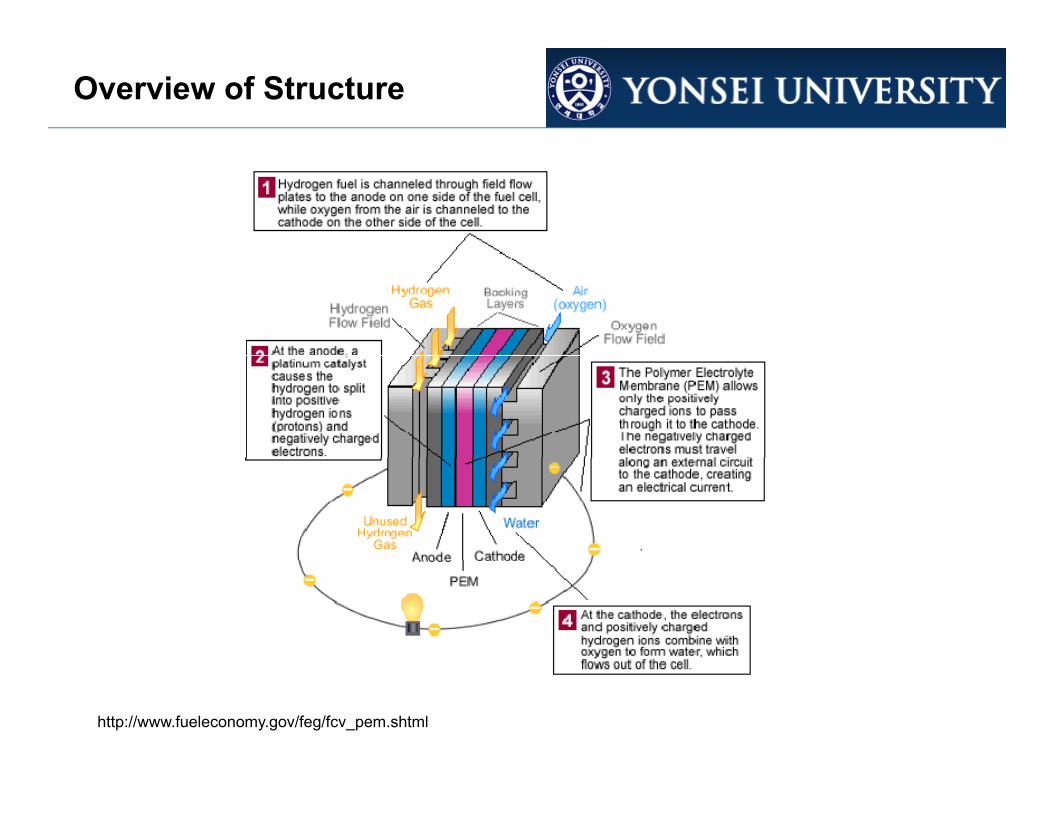
Overview of Structure
http://www.fueleconomy.gov/feg/fcv_pem.shtml
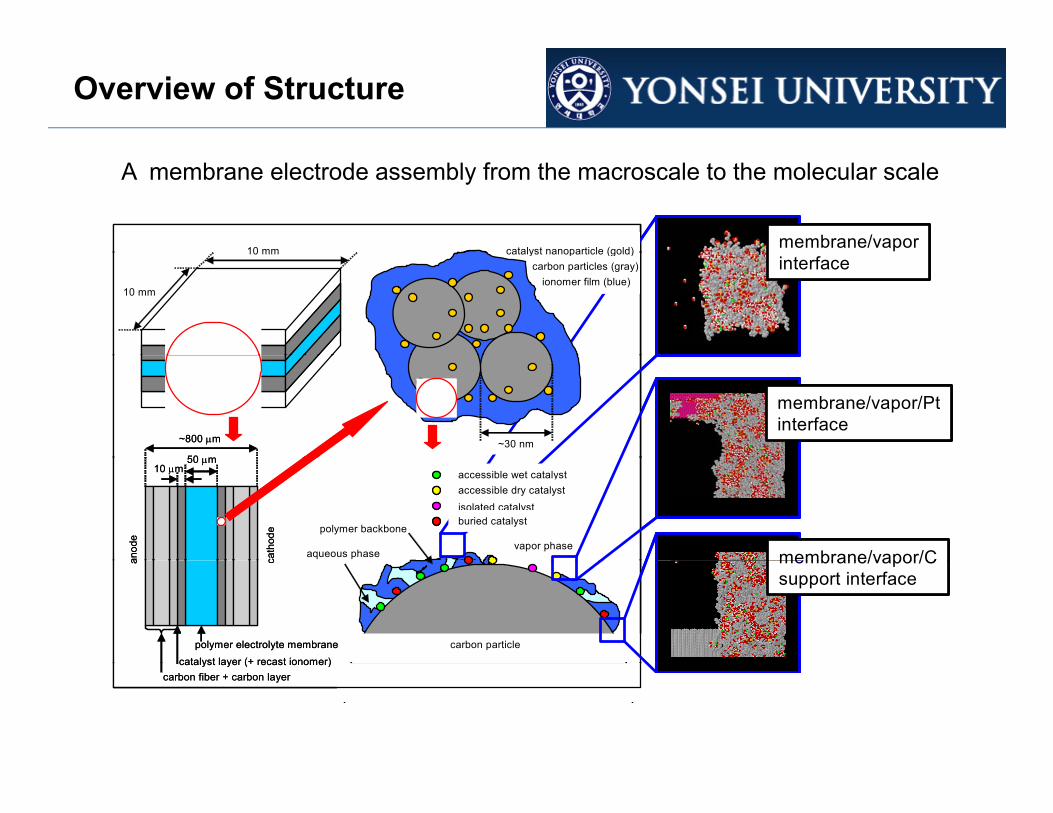
Overview of Structure
10 mm membrane/vaporcatalyst nanoparticle (gold)10 mm membrane/vaporcatalyst nanoparticle (gold)
A membrane electrode assembly from the macroscale to the molecular scale
10 mm
10 mminterface
ionomer film (blue)
catalyst nanoparticle (gold)carbon particles (gray)
10 mm
10 mminterface
ionomer film (blue)
catalyst nanoparticle (gold)carbon particles (gray)
~800 m
50 m
membrane/vapor/Ptinterface
~30 nm~800 m
50 m
~800 m
50 m
membrane/vapor/Ptinterface
~30 nm
polymer backbone
aqueous phasevapor phase
50 m10 m
anod
e
cath
ode
membrane/vapor/C
accessible wet catalystaccessible dry catalystisolated catalystburied catalyst
polymer backbone
aqueous phasevapor phase
50 m10 m
anod
e
cath
ode
50 m10 m
anod
e
cath
ode
membrane/vapor/C
accessible wet catalystaccessible dry catalystisolated catalystburied catalyst
accessible wet catalystaccessible dry catalystisolated catalystburied catalyst
carbon particlecarbon particle
a c
polymer electrolyte membranecatalyst layer (+ recast ionomer)
membrane/vapor/Csupport interface
carbon particlecarbon particle
a c
polymer electrolyte membranecatalyst layer (+ recast ionomer)
a c
polymer electrolyte membranecatalyst layer (+ recast ionomer)
membrane/vapor/Csupport interface
catalyst layer (+ recast ionomer)carbon fiber + carbon layer
catalyst layer (+ recast ionomer)carbon fiber + carbon layer
catalyst layer (+ recast ionomer)carbon fiber + carbon layer
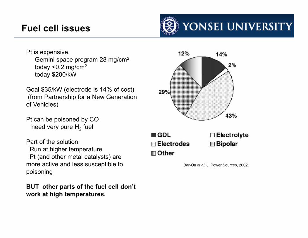
Fuel cell issues
Pt is expensive.Gemini space program 28 mg/cm2
today <0.2 mg/cm2
today $200/kWtoday $200/kW
Goal $35/kW (electrode is 14% of cost)(from Partnership for a New Generation of Vehicles)of Vehicles)
Pt can be poisoned by COneed very pure H2 fuel
Part of the solution:Run at higher temperaturePt (and other metal catalysts) are
more active and less susceptible to B O t l J P S 2002more active and less susceptible to poisoning
BUT other parts of the fuel cell don’t work at high temperatures
Bar-On et al. J. Power Sources, 2002.
work at high temperatures.

proton exchange membranes are polymer electrolytes
Industry Standard Membraneproton exchange membranes are polymer electrolytes
industry standard: Nafion (DuPont)
sulfonic acid at end of side chainNafion (DuPont)
perfluorosulfonic acidend of side chainprovides protons
monomer backbone contains CF2.
side chain
CF2 = gray, O = red, S = orange, cation not shown.

Industry Standard Membrane

Membrane must be Hydrated
Kreuer et al., Chem. Rev. 2004.
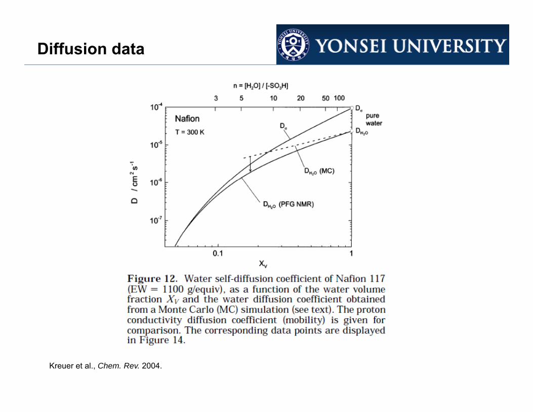
Diffusion data
Kreuer et al., Chem. Rev. 2004.

Conductivity data
Kreuer et al., Chem. Rev. 2004.

High Temperature Fuel Cells
Running a fuel cell at higher temperatures has advantages but poses technological challenges.
Advantages:● requires less catalyst
catalyst more inherently more active at higher temperature because ● lessens the requirement on fuel purity because● lessens the requirement on fuel purity because
catalyst is less susceptible to CO poisoning○ at lower temperature, CO adsorbs irreversibly, occupies sites on the Pt catalyst, preventing those sites from participating in useful electrochemical reactions ○ at higher temperature the CO adsorption isotherm is shifted to the gas phase freeing○ at higher temperature, the CO adsorption isotherm is shifted to the gas phase, freeing up more of the catalyst surface to participate in useful electrochemical reactions
Technological Challenges:● requires advanced membrane technology that maintains a high conductivity at higher● requires advanced membrane technology that maintains a high conductivity at higher
temperatures, by either ○ retaining more moisture at higher temperature, or ○ having a higher conductivity at reduced moisture contents○ moving to a water free membrane○ moving to a water-free membrane

Macroscopic Modeling
Wang, Chem. Rev. 2004.

Macroscopic Modeling
M i d l i d b l diMacroscopic models use macroscopic mass, energy and momentum balances to predict fluxes.
Effective mass transfer coefficients and conductivities are required as inputs.
Wang, Chem. Rev. 2004.

Macroscopic Modeling
Example outputs from macroscopic models: flow field in the bipolar plate channels.
Wang, Chem. Rev. 2004.

Macroscopic Modeling
Wang, Chem. Rev. 2004.

Macroscopic Modeling
Modeling of Catalyst Layers (Electrode/Electrolyte Interface)
Wang, Chem. Rev. 2004.

Modeling Reviews
Weber & Newman, Chem. Rev. 2004.

Modeling Reviews
Weber & Newman, Chem. Rev. 2004.

Modeling Reviews
M d li f C t l t L (El t d /El t l t I t f )Modeling of Catalyst Layers (Electrode/Electrolyte Interface)
Weber & Newman, Chem. Rev. 2004.

Conclusions
In the development of next generation fuel cells, there are several points that become apparent:
● Optimization of membranes with high performance at higher temperatures requires an understanding of the molecular-level mechanism for water and charge transport through the membrane.● This understanding can guide synthetic chemists to develop new membrane● This understanding can guide synthetic chemists to develop new membrane materials with superior performance.● Lecture 02 in this course provides a picture of the current understanding of molecular-level structure of proton exchange membranes.
● The interface between the electrode and electrolyte (the catalyst layer) is the area of greatest ignorance.area of greatest ignorance.● Molecular level understanding of the structure of and transport through these interfaces would be very useful to design nanostructured interfaces with enhanced performance.
L t 03 i thi id i t f th t d t di f● Lecture 03 in this course provides a picture of the current understanding of molecular-level structure of the electrode/electrolyte interface in PEM fuel cells.