
Dynamics equation of motion and Trajectory planning of a 2 DOF RR robotic arm

80 Okubanjo et al., Modeling of 2-DOF…
Futo Journal Series (FUTOJNLS)
e-ISSN : 2476-8456 p-ISSN : 2467-8325
Volume-3, Issue-2, pp- 80 - 92
www.futojnls.org
Research Paper December 2017
Modeling of 2-DOF Robot Arm and Control
Okubanjo, A. A.*, Oyetola, O. K., Osifeko, M. O., Olaluwoye, O. O. and Alao, P. O.
Department of Computer and Electrical & Electronics Engineering, Olabisi Onabanjo University, Ago-Iwoye, Nigeria
*Corresponding author’s e-mail: [email protected]
Abstract The mathematical modeling of two degrees of freedom robot arm (2-DOF) is developed and presented in this paper. The model is based on a set of nonlinear second-order ordinary differential equations and to simulate the dynamic accurately lagrangian and Euler-Lagrange equations were successfully derived and established. The control algorithm is expanded on the derived mathematical equations to control the robot arm in joint angle position and the coupling effect of the robot arm was decoupled so as to gain sufficient freedom to control each arm freely. Proportional-integral-derivate controllers (PIDs) was implemented in the model and the simulation model was developed with the aid of MATLAB and Simulink R2014b version 8.4 simulation tool to investigate the system performance in joint space. According to the results analysis, the robot arm was satisfactorily controlled to reach and stay within a desired joint angle position through implementation and simulation of PID controllers using MATLAB/Simulink. This model serves as simulation platform to test the performance of the robot arm with different joint angles position and to observe the responses prior to the implementation the model in the actual robot arm.
Keywords: Modeling, 2-DOF robot arm, PID controller, Lagrangian and Euler-Lagrange, MATLAB/Simulink
1. Introduction
In this technology-driven economy, the demand for the robot is increasing rapidly and its
applications are widespread across all sectors. The study of robot arm control has gained a
lot of interest in manufacturing industry, military, education, biomechanics, welding,
automotive industry, pipeline monitoring, space exploration and online trading (Mohammed,
2015; O zkan, 2016; Rajeev Agrawal, Koushik Kabiraj, 2012; Salem, 2014; Virgala, 2014)
due to the fact that it works in unpredictable, dangerous, and hostile circumstances which
human cannot be reached. Recently, the robot arm is on increasing demand in health
services to administer drugs to patients and rehabilitate the disabled and aged people; of
which high accuracy and precision with zero-tolerance to error are of high significance for
efficient utilization. (Paper, Wongphati, and Co, 2012; Virendra and Patidar, 2016).
A robot arm is a kind of mechanical device, programmable, multi-functional manipulator
(Sanchez-Sanchez and Reyes-Cortes, 2010) designed with an intention to interact with the

81 Okubanjo et al., Modeling of 2-DOF…
environment in a safe manner. It is a mechanical device in the sense that it has links and
joint that provide stability and durability but are redundant from a kinematic perspective since
the forces involve in the motion are not considered. The problems of high non-linearity in the
coupling reaction forces between joints, as result of coupling effect and inertia loading(Craig,
2005; Munro, 2004; Virgala, 2014) are not well captured from the kinematics perspective.
However, in-depth understanding of dynamic modeling is essential to address the controlling
problem associated with the robot arm.
Modeling, simulation and control of robot arm had received tremendous attention in the field
of mechatronics over the past few decades and the quest for new development of robot arm
control still continues. In literature (Mohammed, 2015), kinematics model of a 4-DOF robot
arm is addressed using both Denavit-Hartenberg (DH) method and product of exponential
formula; and the result under study has shown that both approaches resulted in an identical
solution. In the study (Gea and Kirchner, 2008),the impedance control is implemented to
control the interaction forces of a simulated 2 link planar arm; a mathematical model of a
robot is modelled, linearized and decoupled in order to establish a model-based controller.
Simmechanic is used as a simulation tool to model the mechanics of the robot which permit
the possibility to vary model-based control algorithms. The fundamental and concepts of 5
DOF of educational robot arm study in (Mohammed Abu Qassem, Abuhadrous, & Elaydi,
2010) to promote the teaching of the robot in higher institution of learning. To achieve this, a
detailed kinematic analysis of an ALSB robot arm was investigated and a graphical user
interface (GUI) platform was developed with Matlab programming language which also
includes on-line motional simulator of the robot arm to fascinate and encourage experimental
aspect of robot manipulator motion in real time among undergraduates and graduates.
The research work in (Virgala, 2014) centred on analysing, modelling and simulation of
humanoid robot hand from the perspective of biology focusing on bones and joints. A new
method for the inverse kinematic model is introduced using Matlab functions and dynamic
model of humanoid hand is established using model-based design with aid of
Matlab/Simmechanics. The conclusion of their work is that they established a model in
Matlab which can be used to control finger motion. The author in (Lafmejani and
Zarabadipour, 2014) modeled, simulated and controlled 3-DOF articulated robot manipulator
by extracting the kinematic and dynamic equations using Lagrange method and compared
the derived analytical model with a simulated model using Simmechanics toolbox. The
model is further linearized with feedback and a PID controller is implemented to track a
reference trajectory. It was concluded in the research work that robot manipulator is difficult
to control as result of complexity and nonlinearity associated with the dynamic model.
Mahil and Al-durra, (2016), presented a linearized mathematical model and control of 2-DOF
robotic manipulator and derived a mathematical model based on kinematic and dynamic
equations using the combination of Denavit Hartenberg and Lagrangian methods. In his
work, two different control strategies were implemented to compare the performance of the
robot manipulator.
According to Salem, (2014), a robot arm model and control issues based on Simulink for
educational purpose is presented. It established a comprehensive transfer function for both
the motor and the robot arm which provide an insight into the dynamic behaviour of the robot
arm. It later proposed a model for research and education purposes; which is used to select
and analyze the performance of the system both in open and closed loop systems. (Razali,

82 Okubanjo et al., Modeling of 2-DOF…
Ishak, Ismail, Sulaiman, Ismail and Al, (2010), employed 2-DOF robot arm for agricultural
purposes such as planting and harvesting and computer simulation based on visual basic is
developed which enable the users to control the way the robot moves and grab selected
target according to real line situation. Many authors (Mailah, Zain, Jahanabadi, and A, 2009;
Manjaree, 2017; Salem, 2014) developed a model for the robot arm and controlled the
dynamic response of the robot arm using Simmechanics as a software tool. However, detail
essential functions of each block that describe the mathematical model of the dynamic
equations are not well captured with Simmechanics.
The accurate control of motion is a fundamental concern in the robot arm, where
placing an object in the specific desired location with the exact possible amount of force and
torque at the correct definite time is essential for efficient system operation. In other words,
control of the robot arm attempts to shape the dynamic of the arm while achieving the
constraints foisted by the kinematics of the arm and this has been a key research area to
increase robot performance and to introduce new functionalities. In general, the control
problem involves finding suitable mathematical models that describe the dynamic behaviour
of the physical robot arm for designing the controller and identifying corresponding control
strategies to realize the expected system response and performance. New strategies for
controlling the robot arm has been more recently introduced such as PID (David & Robles,
2012; Guler & Ozguler, 2012; Lafmejani & Zarabadipour, 2014; Rajeev Agrawal, Koushik
Kabiraj, 2012), Fuzzy logic and Fuzzy pattern comparison technique (Bonkovic, Stipanicev,
& Stula, 1999), Impedance control (Gea & Kirchner, 2008; Jezierski, Gmerek, Jezierski, &
Gmerek, 2013), LQR Hybrid control (Humberto, Rojas, Serrezuela, Adrian, Lopez, Lorena &
Perdomo, 2016), GA Based adaptive control (Vijay, 2014), neuro-fuzzy controller (Branch,
2012) and Neural networks (Pajaziti & Cana, 2014). The objective of this research is to
establish a mathematical model which represents the dynamic behaviour of the robot and
effectively control the joint angle of the robot arm within a specified trajectory.
2. Methodology
The dynamics of 2-DOF robot arm was modelled using a set of nonlinear, second-order,
ordinary differential equations and to simulate the dynamics accurately the Lagrangian and
Lagrange-Euler was adopted. The Euler’s formulation is chosen for its simplicity, robustness
(Amin, Rahim, & Low, 2014) energy based property (David & Robles, 2012),easy
determination and exploitation of dynamic structural property and minimal computational
error as compared to Newton-Euler approach (Murray, 1994) to solve the derived
mathematical model. The formulation of the mathematical model is considered crucial in the
research because the control strategy is investigated based on these derived dynamics
equations, hence the model must be accurately predicted to represent the dynamic
behaviour of the robot arm. The control algorithm is expanded on the derived mathematical
model to control the movement of the robot arm within the specified trajectory or workspace,
hence, we further design a PID controller and tuned the PID based on trial and error method
to obtain suitable controller parameters for proper controlling of the robot arm within the
specified trajectory. Simulation studies based on MATLAB and Simulink are performed on
the robot arm taken into the consideration the obtained PID controller parameters and the
obtained parameters are used to validate the mathematical model in the joint space. The
evaluation of the results obtained is presented and discussed extensively concerning
achievement as well as providing recommendations for further work.

83 Okubanjo et al., Modeling of 2-DOF…
2.1 Mathematical Model of 2-DOF Robot Arm
The dynamics of a robot arm is explicitly derived based on the Lagrange-Euler formulation to
elucidate the problems involved in dynamic modelling. Figure 1 shows the schematic
diagram of two degree of freedom (DOF) of the robot arm with the robot arm link1 and link
2, joint displacement are and ,link lengths are and , , represent the masses of
each link and and are torque for the link 1and 2 respectively. In the model, the following
assumptions are made:
i. The actuators dynamics (motor and gear boxes) is not taken into account.
ii. The effect of friction forces is assumed to be negligible
iii. The mass of each link is assumed to be concentrated at the end of each link.
Figure 1: 2-DOF robot arm
First, the kinetic and the potential energies of the system are calculated, the kinetic energy of
the manipulator as function of joint position and velocity is expressed as:
( )
( )
( )
where, ( ) is the nxn manipulator mass matrix and the subscript i denote 1and 2.
Hence, the total kinetic energy of the robot arm is the sum of the kinetic energies ( and
) of the individual link.
( ) ∑
( ) ( )
( )
( )
To calculate and , are differentiated the position equations for at A as well as at
B are written and subsequently, we differentiate the respective positions using inner product
to obtain their corresponding velocity.
( )
( )
( ) ( )
( ) ( )
Considering velocity, it is defined as,
* + [
] ( )

84 Okubanjo et al., Modeling of 2-DOF…
‖ ‖ ( )
[ ] [
] ( )
(
)
( )
Similarly, is computed in the same view
( ) ( )
( ) ( )
( ) (
)
( ) ( )
( )
To reduce the complexity in the derivation, we denote the trigonometry as:
( ) ( )
( ) ( ) ( )
Substituting and
in equation( ), we obtain the kinetic energy of each link as follows:
( )
( )
( )
(
)
( ) ( )
so that the total kinetic energy of the robot arm is obtained from equations ( ) and
( ) and presented as
( )
( )
(
)
( ) ( )
Reference with the datum (zero potential energy) at the axis of rotation, the potential energy
of the robot arm is the sum of the potential energies of the link 1 and link 2 which is obtained
as follows;
( ) ∑
( ) ( )
( ) ( ) ( )
The Lagrange-Euler formulation defines the behaviour of a dynamic system in terms of
works and energy stowed in the system (Urrea & Pascal, 2017). The Lagrangian L is
demarcated as;
( ) ( )
( )
( )
(
)
( )
( )
( )
From this Lagrangian, the dynamic systems equations of the motion are given by:
( )
where L is the Lagrangian function, K the kinetic energy, U the potential energy, the
generalized coordinates torque exerted on .
For the coordinate , the Lagrange’s equation are;

85 Okubanjo et al., Modeling of 2-DOF…
( )
( ) ( )
[( )
] [
]
( )
( ) ( )
[( )
] [ ]
( )
( )
Similarly, for the coordinate , the Lagrange’s equations are:
( ) ( )
( ) ( )
(
) ( )
( )
( )
The derived dynamic equations can be written in terms of the components of inertial matrix,
the centrifugal force and Coriolis force vector and the gravity force respectively and they are
presented as;
( ) ( )
( )
( ) ( )
( ) ( )
( ) ( )
( ) ( )
( ) ( )
( ) ( ) ( )
( ) ( )
The dynamic equations for the robot manipulator are usually represented by the coupled
non-linear differential equations which was derived from lagrangian method;
( ) ( ) ( ) ( )
3. Control Strategy
Proportional-integral-derivate controller (PID) is implemented for effective control of the robot
arm. We need two PID controllers since arm1 and arm2 are dependent on each other; as a
matter of fact, there is a strong interaction between the two arms. However, the coupling
effect needs to be decoupled so as to gain enough freedom to control each arm freely. The
main objective is to make the robot arm to move or stop in the desired position to achieve

86 Okubanjo et al., Modeling of 2-DOF…
the stated objective we defined a desired (set point) joint angle , the objective of robot
control is to design the input torque in equation (37) such that the regulation error :
( )
And the PID control law is expressed in terms of error, as:
∫ ( )
( )
: The desired joint [ ]
: The actual joint angle [ ]
: Angle error [ ]
The closed-loop system for two-degree-of-freedom robot arm shown Figure 2 which provides
insight into the modeling (referred to fig. 3) and the control aspect of the robot arm.
Figure 2: Closed loop system for 2-DOF robot arm control
The closed loop equation of the robot arm is obtained by substituting the control action
in equation ( ) into the robot model( ).
( ) ( ) ( ) ( )
where ( )
According to Murray, (1994), the work done by the motion of the end effectors is expressed
as
∫
( )
where, W is the work done by the end effector, time interval, the linear velocity
vector and F the applied force vector of the motion of the end effector.
This work is the same as the work perform by robot arm, so
∫ ( )
∫
(43)
, the angle velocity vector and τ the applied torque vector and
(44)
Equation 40 is further simplify as:

87 Okubanjo et al., Modeling of 2-DOF…
(45)
It follows that,
( )
Let consider the two-degree-of-freedom (2 DOF) robot arm with joint coordinates where
and and a Cartesian coordinate , is defined as Cartesian corresponding to the
joint position vector [ ] , and the angle velocity and angle acceleration vectors
and respectively and let ( ), where
( )
( )
Where, is the linear velocity, that is
( ) [ ( )
( )] ( )
( ), the function between the angle position and the Cartesian position and the partial
differential of equation ( ) and ( ) with respect to , result in Jacobian matrix J.
( )
[
]
( )
From the equation( ), F is the output of the PID controller and the Jacobian matrix J is
designed as the decoupling part and the corresponding input of the robot arm can be written
as:
*
+ [
] [
] ( )
4. Results and Discussion
Simulink model of 2-DOF robot arm is prepared based on the Lagrangian and Lagrange-
Euler formulation derived in the equation 1 to 38 and the PID controllers are implemented
from the equation 41 and 50. The parameter values for two-degree-of-freedom (2-DOF)
robot arm presented in Table 1 are used for the simulation. This model is further split into
sub-systems to reduce system complexity and size and latter combined as one model as
depicted in Figure 3. In Simulink toolbox PID block is available which is implemented to
control the joint angle. The tuning of control parameters is done using PID tuner and the best
performance of the controller parameter values are presented in Table 2.
Table 1: Parameters of the 2-DOF Robot Arm
Parameter Link 1 Link 2 Unit
5.00 2.0
0.34 0.34
g 9.81 9.81
[ ]
[ ]
[ ]
88 Okubanjo et al., Modeling of 2-DOF…
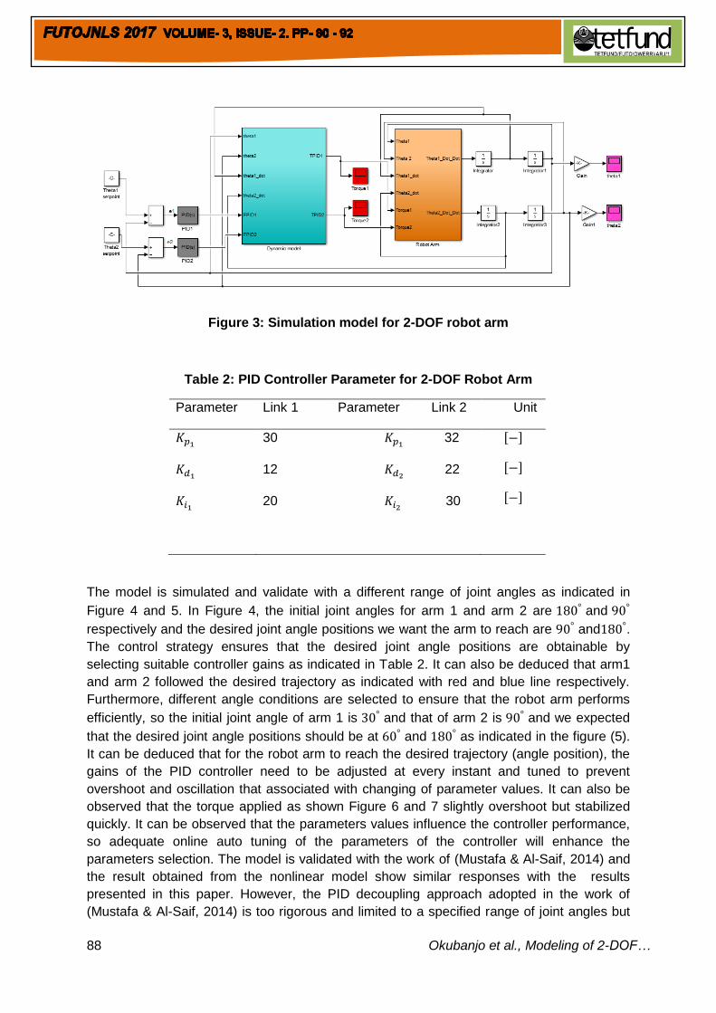
Figure 3: Simulation model for 2-DOF robot arm
Table 2: PID Controller Parameter for 2-DOF Robot Arm
Parameter Link 1 Parameter Link 2 Unit
30 32
12 22
20 30
[ ]
[ ]
[ ]
The model is simulated and validate with a different range of joint angles as indicated in
Figure 4 and 5. In Figure 4, the initial joint angles for arm 1 and arm 2 are and
respectively and the desired joint angle positions we want the arm to reach are and .
The control strategy ensures that the desired joint angle positions are obtainable by
selecting suitable controller gains as indicated in Table 2. It can also be deduced that arm1
and arm 2 followed the desired trajectory as indicated with red and blue line respectively.
Furthermore, different angle conditions are selected to ensure that the robot arm performs
efficiently, so the initial joint angle of arm 1 is and that of arm 2 is and we expected
that the desired joint angle positions should be at and as indicated in the figure (5).
It can be deduced that for the robot arm to reach the desired trajectory (angle position), the
gains of the PID controller need to be adjusted at every instant and tuned to prevent
overshoot and oscillation that associated with changing of parameter values. It can also be
observed that the torque applied as shown Figure 6 and 7 slightly overshoot but stabilized
quickly. It can be observed that the parameters values influence the controller performance,
so adequate online auto tuning of the parameters of the controller will enhance the
parameters selection. The model is validated with the work of (Mustafa & Al-Saif, 2014) and
the result obtained from the nonlinear model show similar responses with the results
presented in this paper. However, the PID decoupling approach adopted in the work of
(Mustafa & Al-Saif, 2014) is too rigorous and limited to a specified range of joint angles but

89 Okubanjo et al., Modeling of 2-DOF…
the method presented in this research work permit flexibility of joint angles selection and
decoupling is dependent on the Jacobian matrix derivation.
Figure 4: The angle positions of the arm
Figure 5: The angle positions of the arm

90 Okubanjo et al., Modeling of 2-DOF…
Figure 6: Torque of theta 1 Figure 7: Torque of theta 2
5. Conclusion
In this paper, the mathematical modeling, control and simulation of a 2-DOF robot arm were
presented. The distinct feature of this approach was the 2-DOF mathematical model that
served as the core element. The approach of using mathematical models, Lagrangian and
Euler-Lagrange were to derive a dynamic model that mimicked the actual robot movement in
real life scenario and to gain sufficient control over the robot joint positions within the desired
trajectory. According to the results analysis, the robot arm was controlled to reach and stay
within a desired joint angle position through implementation and simulation of PID controllers
using MATLAB/Simulink. Also, the result revealed that changes in initial joint angle positions
of the robot arm resulted in different desired joint angle positions and this necessitated that
the gains of the PID controllers need to be adjusted and turned at every instant in order to
prevent overshoot and oscillation that associated with the change in parameters values.
However, an online auto-tuning of the controller parameters can be implemented so as to
enhance the parameters selection. As for future work, a more robust control such as H-
infinity controller as well PID gain scheduling should be a focus of interest in latest research
of robot arm control.
REFERENCES
Amin, A. T. M., Rahim, A. H. A. & Low, C. Y. (2014). Adaptive controller algorithm for 2-DOF
humanoid robot arm. Procedia Technology, 15, 765–774.
https://doi.org/10.1016/j.protcy.2014.09.049
Bonkovic, M., Stipanicev, D. & Stula, M. (1999). Control of robot arm approach by Fuzzy
Pattern comparison technique. Springer, Berlin, Heidelberg, 246 - 252
https://doi.org/10.1007/3-540-48774-3_29
Branch, I. (2012). A new method for position control of a 2-DOF robot arm using neuro –
fuzzy controller. Indian Journal of Science and Technology, 5(3), 2253–2257.
Craig, J. J. (2005). Introduction to Robotics. IEEE Expert, (3rd ed., Vol. 1). Pearson
Education Intenational. https://doi.org/10.1109/MEX.1986.4306961
David, I & Robles, G. (2012). PID control dynamics of a robotic arm manipulator with two
degrees of freedom. Control de Processos Y Robotica, 1–7.
Gea, J. de, & Kirchner, F. (2008). Modelling and simulation of robot arm interaction forces
using impedance control. Proceedings of the 17th World Congress, 15589–15594.

91 Okubanjo et al., Modeling of 2-DOF…
https://doi.org/10.3182/20080706-5-KR-1001.0467
Guler, S. & Ozguler, A. B. (2012). Tracking and regulation control of a 2-DOF robot arm with
unbalance. 2012 17th International Conference on Methods and Models in Automation
and Robotics (MMAR). IEEE. https://doi.org/10.1109/MMAR.2012.6347874
Humberto, J., Rojas, C., Serrezuela, R. R., Adrián, J., López, Q., Lorena, K. & Perdomo, R.
(2016). LQR hybrid approach control of a robotic arm two degrees of freedom.
International Journal of Applied Engineering Research ISSN, 11(17), 973–4562.
Retrieved from http://www.ripublication.com
Jezierski, E., Gmerek, A., Jezierski, E. & Gmerek, A. (2013). Impedance controllers for
electric-driven robots impedance controllers for electric-driven robots, 7, 13–20.
Lafmejani, H. S. & Zarabadipour, H. (2014). Modeling , simulation and position control of
3dof articulated manipulator. Indonesian Journal of Electrical Engineering and
Informatics (IJEEI), 2(3), 132–140. https://doi.org/10.11591/ijeei.v2i3.119
Mahil, M. S., & Al-durra, A. (2016). Robotic Manipulator, (October), 16–19.
Mailah, M., Zain, M. Z. M., Jahanabadi, H., & A, M. A. B. R. et al. (2009). Mathematical
modelling and simulation of the human To all Intelligent Active Force Control Research
Group (IAFCRG) Research management Centre ;Universiti Teknologi Malaysia.
Mohammed, et al. (2015). Kinematics modeling of a 4-DOF robotic arm. Proceedings - 2015
International Conference on Control, Automation and Robotics, ICCAR 2015, (May
2015), 87–91. https://doi.org/10.1109/ICCAR.2015.7166008
Mohammed Abu Qassem, Abuhadrous, I. & Elaydi, H. (2010). Modeling and Simulation of 5
DOF educational robot arm. In: 2010 2nd International Conference on Advanced
Computer Control, 569–574. IEEE. https://doi.org/10.1109/ICACC.2010.5487136
Munro. (2004). Manipulator control theory and practice. Theory and Practice.
Murray, R. M. (1994). A Mathematical Introduction to robotic manipulation.
Mustafa, A. M. & Al-Saif, A. (2014). Modeling, simulation and control of 2-R robot. Global
Journal of Researches in Engineering Robotics & Nano-Tech, 14(1), 49–54.
O zkan, B. (2016). Guidance and control of a planar robot manipulator used in an assembly
line. Transactions of the Institute of Measurement and Control.
https://doi.org/10.1177/0142331216657800
Olanrewaju, O., Faieza, A. & Syakirah, K. et al. (2013). Current trend of robotics application
in medical. IOP Conference Series: Materials Science and Engineering, 46, 12041.
https://doi.org/10.1088/1757-899X/46/1/012041
Pajaziti, A. & Cana, H. (2014). Robotic Arm control with neural networks using genetic
algorithm optimization approach, 8(8), 1431–1435.
Paper, C., Wongphati, M. & Co, H. (2012). Where do you want to use a robotic arm ? And
what do you want from the robot ?, (September).
https://doi.org/10.1109/ROMAN.2012.6343773
Rajeev Agrawal, Koushik Kabiraj, R. S. et al. (2012). Modeling a controller for an articulated
robotic arm. Intelligent Control and Automation, 3, 207–210.
https://doi.org/10.4236/ica.2012.33023
Razali, M. H., Ishak, W., Ismail, W., Sulaiman, N., Ismail, N. & Al., E. (2010). Computer
simulation technique for two degree of freedom agriculture robot Arm, 1(2), 15–17.
Manjaree, S., M. T. et al. (2017). Modeling of Multi-DOF robotic manipulators using sim-
mechanics software. Indian Journal of Science and Technology, 9(48).
https://doi.org/10.17485/ijst/2016/v9i48/105833
Salem, F. A. (2014). Modeling, simulation and control issues for a robot ARM. Education and
Research (III). International Journal of Intelligent Systems and Applications, 6(4), 26–
92 Okubanjo et al., Modeling of 2-DOF…
39. https://doi.org/10.5815/ijisa.2014.04.03
Sanchez-Sanchez, P., & Reyes-Cortes, F. (2010). Cartesian control for robot manipulators.
in robot manipulators trends and development, 165–213. InTech.
https://doi.org/10.5772/9186
Urrea, C. & Pascal, J. (2017). Parameter identification methods for real redundant
manipulators. Journal of Applied Research and Technology, 15, 320–331.
Vijay, M. et. al. (2014). GA based adaptive controller for 2DOF robot manipulator. IFAC
Proceedings, 47(1), 670–675. https://doi.org/10.3182/20140313-3-IN-3024.00085
Virendra, Patidar, R. T. et al. (2016). Survey of robotic arm and parameters. In 2016
International Conference on Computer Communication and Informatics, ICCCI, 1–6.
IEEE. https://doi.org/10.1109/ICCCI.2016.7479938
Virgala, I. et al. (2014). Analyzing, modeling and simulation of humanoid robot hand motion.
Procedia Engineering, 96, 489–499. https://doi.org/10.1016/j.proeng.2014.12.121
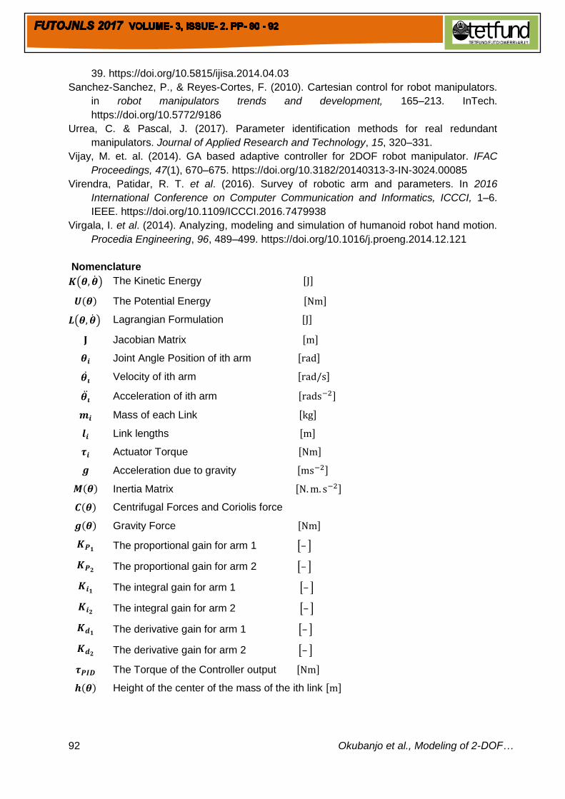
Nomenclature
( ) The Kinetic Energy [ ]
( ) The Potential Energy [ ]
( ) Lagrangian Formulation [ ]
Jacobian Matrix [ ]
Joint Angle Position of ith arm [ ]
Velocity of ith arm [ ]
Acceleration of ith arm [ ]
Mass of each Link [ ]
Link lengths [ ]
Actuator Torque [ ]
Acceleration due to gravity [ ]
( ) Inertia Matrix [ ]
( ) Centrifugal Forces and Coriolis force
( ) Gravity Force [ ]
The proportional gain for arm 1 [– ]
The proportional gain for arm 2 [– ]
The integral gain for arm 1 [– ]
The integral gain for arm 2 [– ]
The derivative gain for arm 1 [– ]
The derivative gain for arm 2 [– ]
The Torque of the Controller output [ ]
( ) Height of the center of the mass of the ith link [ ]


![DEVELOPING UPPER LIMBS FOR SOCIAL HUMANOID ROBOT NADINEimi.ntu.edu.sg/.../20_November_2018/SINHA_Anoop_Kumar_20_Nove… · Fig. 1 : 7 DOF of Human Arm [1] Fig. 2 : 27 DOF of Human](https://static.fdocuments.net/doc/165x107/5edd5b32ad6a402d66686ad9/developing-upper-limbs-for-social-humanoid-robot-fig-1-7-dof-of-human-arm-1.jpg)