
Modeling method to visually reconstruct the historical Vasa ship with the help of a 3D scanned
39
Beteckning:________________ Faculty of Engineering and Sustainable Development Modeling method to visually reconstruct the Historical Vasa Ship with the help of a 3D scanned point cloud Henrik Carlsson June 2011 Bachelor Thesis, 15 hp, C Computer Science Creative Computer Graphics Supervisor: Sharon Lazenby Examiner: Torsten Jonsson
Transcript of Modeling method to visually reconstruct the historical Vasa ship with the help of a 3D scanned

Beteckning:________________
Faculty of Engineering and Sustainable Development
Modeling method to visually reconstruct the Historical Vasa Ship with the help of a 3D scanned point cloud
Henrik Carlsson
June 2011
Bachelor Thesis, 15 hp, C
Computer Science
Creative Computer Graphics
Supervisor: Sharon Lazenby
Examiner: Torsten Jonsson

Modeling method to visually reconstruct the historical Vasa ship with the help of a 3D scanned point cloud
by
Henrik Carlsson
Faculty of Engineering and Sustainable Development
University of Gävle
S-801 76 Gävle, Sweden
Email:
Abstract
A point cloud derived from scanning the actual Vasa ship is used for an
accurate visualisation. Both manual and automatic mesh techniques where
utilized in the modelling of the Vasa ship to overcome problems of poor
resolution in the point cloud and computing power. A combination of
manual and automatic techniques resulted in a 3D model optimized for use
within animation software. The method presented in this paper utilized a
method that allows the user to keep control over topology. The polygon
count is kept to a minimum and one can still remain certain that the
measurements and realism from the point cloud is maintained. Keywords: 3D visualization, point cloud, integration, laser scanning.

Acknowledgements A large thanks to Sharon Lazenby for all her help and support. I could not have asked
for a better thesis supervisor.
I also want to thank Jacob Jacobsson at the Vasa museum in Stockholm
I also want to thank Micheal Pääbo at PCG AB in Linköping for his help forming the
idea behind this project

Table of Contents
1 Introduction ......................................................................................................... 1 1.1 Aim of research ............................................................................................................. 1 1.2 Research questions ........................................................................................................ 2 1.3 Outline of methods ........................................................................................................ 2 1.4 Possible outcome of the research ................................................................................... 3
2 Theoretical Background ..................................................................................... 4 2.1 Laser scanning methods and techniques ........................................................................ 4 2.2 Triangulation scanners .................................................................................................. 4 2.3 Time of flight scanners (tof) .......................................................................................... 4
3 Mesh Creation .................................................................................................... 5 3.1 Delaunay - based methods ............................................................................................ 5 3.2 Surface - based methods ............................................................................................... 5 3.3 Volumetric methods...................................................................................................... 5 3.4 Deformable surfaces ..................................................................................................... 5
4 Post Processing ................................................................................................... 6
5 Laser Scanners and Cultural Heritage Visualization ..................................... 7
6 Theoretical Background Findings .................................................................... 8
7 Model Goals and Clarification .......................................................................... 9 7.1 Material provided by the museum ................................................................................ 9 7.2 Initial testing and experiments ....................................................................................... 9
8 Results ............................................................................................................... 12 8.1 Methods for creating the hull ....................................................................................... 12 8.2 Methods for creating the deck and gunwale ................................................................ 14 8.3 Methods for creating the stern, statues and ornaments ................................................ 14 8.4 Methods for modeling the bow .................................................................................... 17 8.5 Methods for modeling the masts .................................................................................. 17 8.6 Adding details with textures ........................................................................................ 18 8.7 Method analysis of models .......................................................................................... 18 8.8 Resembling model and rendering ................................................................................ 18
9 Discussion ......................................................................................................... 20 9.1 A mesh for 3D software ............................................................................................... 20 9.2 Effective workflow method ......................................................................................... 22 9.3 Artistic and manual approach ...................................................................................... 22 9.4 Details with automatic mesh creation .......................................................................... 23 9.5 Authenticity be preserved ............................................................................................ 24
10 Conclusion ...................................................................................................... 25
11 Future Development ....................................................................................... 26
References ................................................................................................................... 27
Appendix 1: ............................................................................................................... 31
Appendix 2: ............................................................................................................... 32

1
1.0 Introduction
Laser scanning can be used for measuring or the creation of three dimension (3D)
models. The laser scanner is able to create a Point Cloud which is determined by the
laser distance to the object, time of flight and triangulation which are the predominate
techniques used. [1] Laser scanning provides the user the ability to recreate physical
objects with a great precision, which makes it a suitable tool for engineers. May it be
reverse engineering or as a visualizing aid, laser scanning is a technique and practice
that is expanding into commercial 3D production.
It has been shown that laser scanning can be used with satisfactory results when trying
to preserve and document cultural buildings, statues and monuments. [2] This is due to
the accuracy that can be acquired with laser scanner, and laser scanned point clouds to
mesh methods. However to preserve accuracy a dense point cloud is needed, and
additional calculating power to be able to visualize and create 3D meshes from the
cloud. Modern scanners cannot separate a flat area from an area with curvature, thus
the result is an equal amount of points spread over the whole object. When the point
cloud is translated into a mesh, an equally dense mesh based of triangles will be
created. And also, flat areas will have the same amount of polygons as areas with
curvature. This makes it hard to create an optimized mesh suitable for animation and
manipulation to use in a 3D software package, such as 3D Studio Max [3] or Autodesk
Maya. [4] There are tools for decimation that will try and take the shape of the object
into account. However, these steps can be ignored if the final goal is an object suitable
for 3D animation software as Autodesk Maya.
This research paper will demonstrate the workflow from Point Cloud to mesh
representing the ship Vasa. The ship Vasa is a historical ship that sat sail in 1628 and
sunk on her first voyage just outside of her home harbor. Vasa was made to chock and
impress Swedish enemies, a testament to Sweden‟s new found role as an European
superpower in the early 1700 century. [5] Focus will be on optimization and the use of
manual labor to create a good balance between effectiveness and performance. The
model must not lack in details or in accuracy, as well perform in a satisfactory manner
in 3D software when it pertains to animating and rendering.
1.1 Aim of research
The aim of this research is to create a model of the ship Vasa outside and inside. This
project is performed in collaboration with the Vasa museum in Stockholm. [5] The
goal is to create a realistic model of the ship Vasa before she sank with the help of a
point cloud generated from a laser scanner. The point cloud will provide an exact
reference of the ship. The appearance before the ship sank is determined by the Vasa
museum and the 3D model will not contradict or sway from their view based on
extensive testing.
It is also of great importance that the final model handles well in a 3D software
environment, and is optimized for animation and interaction. This will be a case study,
and the methods will be evaluated throughout the work

2
1.2 Research questions
There are different problems and questions to be answered in the upcoming research
report.
Is it at all possible to obtain a mesh from the Vasa ship point cloud that is
usable in a 3D software program for animating, using an automatic approach?
If this is not achievable, what manual workflow will provide the best balance
between speed, quality and usability with the limited funds available?
How can the authenticity of the object be preserved, when one introduces
human error and judgment using a more manual approach?
How will the fine details be made on the ship, the stern for example without
the help of automatic mesh creation?
1.3 Outline of methods
To obtain a mesh that is usable in a 3D software program for animating, using an
automatic approach will be answered by empirical research. Testing's will be made to
see if it is possible to create a mesh that meets the recruitments. 3ds Studio Max has
the ability to import point clouds, therefore with the help of Autodesk 3ds Studio Max
and Autodesk Maya a 3D model will be created. [3] [4] If possible, I will use
Polyworks [11] or a similar program to do some creation test with point cloud that has
been supplied from the Vasa museum. [5] I will then try to create different sections of
the ship, and the testing from that will help me answer the question.
The question regarding what workflow that will provide the best balance between
speed, quality and usability with the limited funds available, will be answered by
using Zbrush or Mudbox in combination with a 3D software program, such as 3D
Studio Max. Alternative a photo to mesh method will be utilized. [6] [7] [8]
How will the fine details be made on the ship, the stern for example without the help
of automatic mesh creation? This question will be answered with the use of known
techniques for modeling detailed objects. Known techniques in this case would be the
use of ZBrush or Mudbox to create fine details. [6] [7] Because of the time limit of
this project I hope to find a method that is reasonably effective and time efficient.
How can the authenticity of the object be preserved, when one introduces human error
and judgment? This question will be determined by closely measuring different parts
of the model on continual bases to assure that no creative decisions delude the
authenticity.

3
1.4 Possible outcome of the research
It will be of great difficulty to create a good optimized mesh from an automatic mesh
creation program, or at least for some parts of the ship, concerning its high level of
detail, the stern for example. The ship consists of more than 700 statues. [2] And to be
able to recreate these parts automatically, they would have to be scanned with a very
high resolution. And if this is possible, the mesh itself would have to be very detailed
and with a high resolution.
I think that the use of Displacement Maps and Normal Maps on a simpler mesh would
be more effective. A normal map is an image that contains normal information, which
is used when rendering instead of the objects actual normals, by doing this an object
may appear more detailed than it actually is. [9] Displacement maps deforms the 3d
object by moving individual vertices based of a grey scale image, this is accomplished
during rendering. [10] The ship's hull may prove to be easier to recreate automatically,
because of its simpler shapes. However, there will be problems with normal directions
and holes despite resolution or complexity of shapes.
I believe that programs such as PolyWorks [11] specialized in point cloud to mesh
operations, will outperform the manual approach concerning speed. I hope that I will
be able to obtain some models processed by 3D scanner software professionals. My
attempts in the program are not as valid as for a professional user; therefore I will
probably not be able to create the best results regarding my inexperience with the
program. However from my findings, I should be able to tell if the results are
upgradable. I also suspect that a valid workflow will be to create different parts in
Polyworks or similar program, extract those to a 3D software package, and recreate a
solid and functional topology over the imported mesh.
Another outcome that I am seeking is also what capacity the quality of the point cloud
plays and I am guessing that it plays a great deal, concerning quality and equipment
used.
I also think that my findings will show that the full manual control from the start of
the modeling will result in a fully capable model for use in 3D software, such as
Autodesk Maya or 3d Studio Max, because it renders quicker and holds a high quality
in measurements and quality.

4
2.0 Theoretical Background
Below will be a brief overview of the point cloud to mesh pipeline, and its uses for
documenting and visualising cultural heritage sites and objects.
2.1 Laser scanning methods and techniques
Typical workflow when working with a 3D scanner with the end goal of producing a
3D model is as follows; data acquisition, registration, calibration, noise reduction, and
finally surface modeling. [12] It starts with the actual measurements, which is
visualized as a point cloud, different points consist of x, y, z values. When that is
completed, orientation is needed. [12] If the scanned object is large, multiple scans are
necessary to capture the whole object. These different parts are then put back together
to represent the whole object.
Calibration is checked at regular intervals to remove systematic effects. [12] The goal
of the calibration is to achieve a higher accuracy. [12] Noise reduction and surface
modeling will need the use of extensional software, for example Polyworks. There are
quite a few different programs with their own or similar algorithms to take care of
noise and surface triangulation. Resolution of 3D scanners is controlled by the
distance between neighboring points. [13] The smaller the distance between points,
the higher the resolution. Often areas with low geometric definition are scanned on a
lower level, and more complex areas are rescanned with a higher resolution.
Terrestrial scanners also have the ability to record color with an integrated camera
which then can be applied on a feature model. [14] Laser scanners may be organized
in to two categories, time of flight and triangulation scanners. [15]
2.2 Triangulation scanners
First a light is projected upon the object, either as a line or a spot or even some kind of
pattern with the help of a mask. [13] A charge-coupled device camera also known as a
CCD camera then senses the reflected light from the object, the systems software then
calculates the depth value. It can be converted in to x, y, z point position using the
previous calibrated data containing position and orientation of the light source and
sensor. [13] When using a triangulation scanner, the objects reflective properties have
to be taken in to account. [13] This is because the triangulation scanners have shown
bad performance scanning shiny objects or objects with low reflecting power, also
called Albedo and high Subsurface Scattering. [13]
2.3 Time of flight scanners (tof)
Time of flight scanners sends out a short pulse of light against the scanned object. It
then calculates the time it takes for the reflected light to return. The system can then
estimate the distance. [13]

5
3.0 Mesh Creation
Different problems may arise when the meshing process is initiated. Holes and gaps
may occur in the mesh due to gaps in the laser scanning coverage. [16] Other
problems are that there is not enough resolution in the point cloud to accurately
portray the object in 3D. [13] Mesh creation can be organized into four categories,
which are listed in the following subtopics, according to Fausto Bernardini who works
at IBM research center and Holly Rushmeier who is a professor at Yale. [13]
Due to lack of sufficient mathematical knowledge and advance research, meshing
methods are only surveyed and referenced here for future studies. This is because
rewriting without sufficient knowledge may lead to deluded information.
3.1 Delaunay - based methods
This category contains methods that stems from the Delaunay triangulation method.
[17] Examples consist of Alpha shapes [24], Wrap complex, used in the software
Geomagic [25], and the Crust method, with the use of Varonoi diagram. [21]
3.2 Surface - based methods
One of the advantages with surface based method is that it can handle a small amount
of noise and is capable of processing large datasets. [13] Examples include the
Zippering method [26], and Venn diagrams method. [27]
3.3 Volumetric methods
Well suited for the creation of water-tight models without holes and gapes. Volumetric
methods perform by calculating a signed distance field, followed by the extraction of
the zero-set of the trivariate function by applying the marching cube algorithm. [13]
[29] [31] [32] Differences between the different methods in this category are based on
how the signed distance is calculated from the data. [13]
3.4 Deformable surfaces
An initial shape usually a polygonal mesh can be modified by constraints and the
scanned data information. [19] Examples of this includes; Pentland and Sclaroff [32]
and Terzopoulos and others. [33]

6
4.0 Post Processing
Regardless of technique used for mesh creation post processing is almost always
needed. Commonly post processing is used to lower the resolution of the mesh. [13] It
may also be necessary as stated above to fill holes and gapes in the mesh. [23]

7
5.0 Laser Scanners and Cultural Heritage Visualization
To preserve the authenticity of our culture heritage, the data accumulated for either
reconstruction, visualization or documentation, it is crucial that the data is correct and
adequate. Terrestrial laser scanning have shown that the method is suited for the above
criteria's. [12] One of the mayor advantages of laser scanning concerning cultural
heritage is that there is no need of physical contact with the object, and hence no
danger of damage exists. [1] The point data can be used to create a 3D object. It may
then be viewed by a wider audience, and databases may also be created to further help
the catalogisation and preservation of our cultural heritage. [1]
The use of Photogrammetry in combination with laser scanning has shown to be an
effective technique when visualizing and documenting complex heritage sites. [36]
[37] Photogrammetry is a technique that uses pictures to create geometric surfaces.
[35]
There is also different techniques that can be used together to achieve great results, for
example the use of the engineering software CAD. [36] A. Georgopoulos and M.
Modatsos used tourist slides, engineering drawings and geodetic measurements to
model the church of Holy Sepulhre in Jerusalem. [37, 38] El-Hakim in 2003 wrote, "A
Hierarchical 3D Reconstruction Approach for Documenting Complex Heritage Site"
and came to the conclusion that an effective use of different techniques, such as
Photogrammetry, laser scanning, and semi-automatically modeling based from floor
planes and engineering drawings is a valuable approach. The combination of
techniques also generates highly accurate results, with no loss of detail and with a time
reduction. [37]
The Michelangelo project executed by the Stanford University scanned ten statues
created by Michelangelo. The most famous being the statue of David. The final
models were large. One dataset contained two billion polygons. A special program
was developed to be able to show the large models in realtime. At the time of the
report, no 3D modeling software was able to handle such large models. [38]
Animation of point cloud meshes are discussed briefly by J. A. Beraldin in 2002 -
2005, a fly-through of the Byzantine Crypt was rendered. The scene was rendered in
3D Studio Max containing 400,000 faces, 1/5 of maximum texture resolution. It stated
that at the time of the animation, there was not sufficient computer power to render
any larger scenes. [36] In early 2005, another animation was created, now the scene
contained five million faces. The texture quality was also set at maximum level. It is
noted in the report that this is an important improvement from the animation realized
in 2002. [36] The time it took to render the above frames was not declared.

8
6.0 Theoretical Background Findings
The research around laser scanners and automatic mesh creation is a highly
complicated field. Much of the resent research revolved around different techniques
for automatic mesh creation, post processing and the evolution of laser scanners.
Manual approaches to mesh creation is hardly mentioned or discussed, I think that it is
because of the general strive automated every step in the point cloud to mesh pipeline,
and by doing so preserve time, and enhance quality and usability.
Point cloud importers for different 3D software, such as 3D Studio Max, suggest that
there are different techniques and workflows to visualise a point cloud and a resulting
mesh. [1] The reason for this must primarily be because of the complex meshes that
the automatic mesh creation methods produces. Combined with the accompanying
problem of sufficient reduction without a loss of quality, much of the research
revolved around different algorithms for automatic mesh creation and post processing.
This suggested that there are still problems with the techniques that are current today.
However, the many successful visualisations of historical objects as the Michelangelo,
also points to the fact that heavy meshes for example, is not always a problem.
Optimal meshes are not a must when visualising a historical object which the
Michelangelo project shows. However, it also states that the laser scanned David
model cannot be used in a 3D animation software environment. Therefore, the
techniques used by the Stanford University would not be viable for game model
creation or animation. The Michelangelo project and the work performed by J. A.
Beraldin, in 2005, were focused on the visualization of the objects as they appear
today. As a result, texture information can be derived from the scanning site with the
help of one or several cameras. If the goal is to recreate and restore an object that has
been damaged by time or the elements, it will prove difficult to perform texture
operations, such as UV-coordinates layout and texture creation on models containing
two billion faces, or even five million faces.

9
7.0 Model Goals and Clarification
The final model should represent the real Vasa ship in size. Proportions should also be
accurate to the real ship. Color of the ship will be determined using information from
the museum. Due to the damage, the ship has suffered since its first and last voyage in
1628. Some details have been lost and cannot be included in the point cloud which is
an exact represent of the way Vasa appears today. [40]
The physical model in scale one to ten as built by the Maritime Museum in Stockholm
will be used as a secondary reference. The physical model is also in color. The color
schemes have been heavily researched by the museum and are accurate. [41]
Primary, the model will be based on the point cloud, however finer details will have to
be retrieved from the physical model and pictures from the museum.
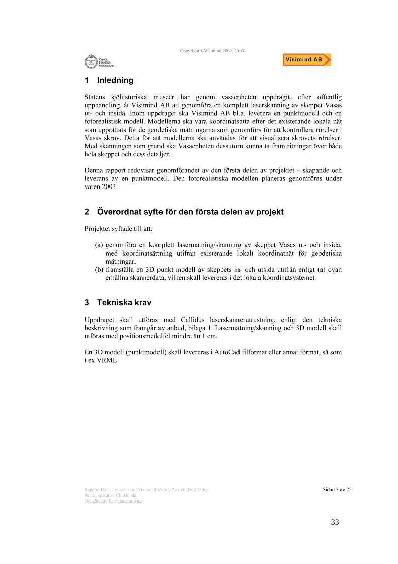
7.1 Material provided by the museum
The point cloud handed to me from the Vasa museum was scanned by a company
named Visimind AB. It was created between 2002 and 2003. The scan was performed
with Callidus laser scanner equipment, see appendix 2. The goals of the scan were as
follows:
Scan the whole ship, inside and outside
Create a 3D point model of the whole ship
Keep position error down to one centimetre
The Vasa ship was scanned from 350 locations, between 750 and 2,500,000 points
depending on complexity. The stern which has many sculptures and ornaments was
scanned with the highest resolution, while the hull could only be scanned at a lower
resolution. The different scans were put together and assigned a common coordinate
system in Callidius software, see appendix 2.
Material received for this research project is a 3D point cloud in .cld format, which
included 18 files in total. For the Callidus project files or .cld, I also received the
Callidius software. The original scan files were provided in .lms and .lmf format.
7.2 Initial testing and experiments
There were some initial problems acquiring the point cloud software. Therefore, I tried
to work around it by using Autodesk Maya. It was difficult to find any free point cloud
viewers or importers for Maya. Later a .ply importer created by Richard Harding of
the Sony Playstation group was found, but it was not needed at that point [42]. Point
measurement data was then exported from Callidius software to text files. Each .cld
file contains around 10-60 scans depending on the file. A simple macro was used to
export every scan to a folder containing all of the other scan files.
These text files were then imported into Pointtools (Pts) which have a 30 day trail.
Pointtools is a point cloud viewer primarily with no opportunity to edit the cloud. [43]
However, the ability to combine multiple text files to one file made it a useful
program. I could also export the combined cloud as a .pts which is a standard file
conversion for point clouds. Pts file format is also demanded for 3ds Studio Max point

10
cloud importer. The Pts files are files that contains the point information, x, y, z
location of points in space, followed by alpha information which in this case there
were none, therefore 0 0 0. [43]
With the help of VRmesh studio 6.0, the exported Pts files were optimized, that
includes removing unnecessary parts of the point cloud. [44] The .cld files contained
coordinated scans, however they were not optimized. When an object is scanned parts
of the surroundings is registered, and these parts need to be deleted. [12] It is
important to remove as many unnecessary points as possible to speed up the
performance.
A .pts file was used which included both starboard and portside of the ship to create a
script in Python for Autodesk Maya. [4] Purpose of the script was to recreate the hull
with curves inside of Maya. The script searched through the .pts files and found
numbers that matched each other in the Z coordinate. The Z coordinate follows the
length of the ship. The criteria were that there must be more than 200 matches. Lower
numbers would result in to small curves that do not help the overall representation.
The matching numbers was then written out to another text file, and sorted in Y
coordinate, and spliced in the centre a left and right side was obtained. The sorted text
files, one for the right and one for the left, was then run inside of Maya, and a curve
point was created at every point numbered in the text file. This resulted in a curve that
spanned around the hull which is shown in Figure 2.
Figure 2. Curves inside Maya.
The script was then recreated with more text files that covered the whole hull of the
ship. Both cubic and linear curves were tested, where linear curves performed the best
and provided a more exact result. However, the technique did not produce a
satisfactory result. The shared amount of points and the noise level created uneven and
very jagged curves. A min and max deviation attribute would have been implemented
to future sort the points and reduce the curve noise. Searching and sorting files
containing millions of points proved to be a slow process. And the technique was
abandoned due to the finding of a Point Cloud Importer for 3ds Studio Max. [45]
Autodesk labs Point Cloud Importer and .pts converter provides the user with the
ability to import point cloud data in to 3ds Studio Max and visualize each point. The

11
.pts file format is prompted upon, and the accompanying .pts to the .ptsb converter,
converts the .pts files into binary code to speed up performance. [45] The system used
during this project was able to visualize two million points with only minor
performance setbacks. Within the plug-in, a level of detail can be set, as well as the
color of the points are editable.
A draft of the hull was created using the point cloud plug-in. There are some problems
using merely a point cloud as reference. In different angles, it is hard to determine
shapes and details which is shown in Figure 3.
Figure 3. Screenshot of 3D Studio Max Viewport.
My first thought was to use the snap ability within 3ds Max to snap vertices to
appropriate points in the cloud. This did not work on my system, with 3ds Studio Max
2011, therefore vertices had to be located manually. A rough model of the hull was
easy to create in this method. However, I also realised that it was hard to determine
detail and model them correctly. It was important to preserve the accuracy in the
model and not turn to images for reference.
Both the techniques at this point proved suitable for rough modeling, the hull, location
of masts, and for the general outlines. I could not with certainty determine any of the
many details on the ship, which was needed to create a realistic representation. It is
important that all parts of the ship are authentic in position and size. Using the point
cloud was also very time consuming and not effective. And because of the size of the
Vasa ship, the final method must be able to allow me to model details with certainty
and be reasonably effective. Time efficiency is also important because of the timetable
for the project but also for my research if there is a valuable manual method for mesh
creation using a point cloud.

12
8.0 Results
Like a chicken fence a mesh is built up by lines also called edges. A polygon is then
drawn between its lines forming a water tight surface. The composition of the edges is
called topology. Topology is important for multiply reasons. A thought out topology
that is easy to overlook are easier to work with but there is also technical reasons for
maintaining good topology. One such technique reason is that the mesh is able to hold
on to its details when subdivided or smoothed.
Subdividing and smoothing are operations which increases the resolution of the mesh,
by splitting exiting polygons to smaller pieces. A too high focus on topology during
the modeling process may hinder effectiveness. It may be beneficial to address
topology issues when the model has the intended shape. Hence, there are multiple user
tutorials on different sites and forums explaining retopology methods. [46] Therefore,
predominant methods used during the building of the ship Vasa are inspired by
retopology methods and manual mesh construction.
8.1 Methods for creating the hull
The final method is based on the use of Geomagic 10 software. Geomagic 10 is
software specialized in creating meshes from point clouds. [47] The clean and
optimized cld files are exported from VRmesh as .ply file format and imported in to
the Geomagic program. The point cloud is split into smaller pieces covering the hull.
These smaller parts are then meshed inside Geomagic. Inside Geomagic, there is a
point to mesh wizard that I found very useful, it progresses through three vital steps in
creating a mesh from a point cloud. [47] This allowed a novice new to the program to
learn quickly.
Step one is to use the Select Disconnected Points Tool, which selects any cluster that
is disconnected from the main body. [48] This tool proved to be very useful when
trying to delete unnecessary points inside the ship without damage to the hull. The
cutting function inside of VRmesh depends on the camera angle, or a selection brush
and both of the methods demanded a great deal of time.
Step two is to select the Outliners Tool, where this tool also tries to remove
unnecessary points and unwanted isolated points. [48] With a sensitivity of 66.6 good
results were achieved. The select Outliners Tool allowed me to clear windows and
port holes of unwanted points automatically. A test on the stern with a section of the
point cloud containing 1,600,419 points was reduced to 1,550,796 without loss of
important details.
Third step is a Uniform Sample. Uniform Sample reduces the number of points on flat
surfaces uniformly. However, it reduces the number of points on curved surface to a
specified density. [48] The user selects the amount of point reduction in flat regions,
and then specifies the extent to which to preserve curvature. In my case, I use absolute
spacing set by default, with a changing degree depending on the amount of points for
example 0.010447mm, and curvature priority set to above 5 depending on region, in a
scale 1 to 11. This system provides a satisfactory result regarding point reduction and
resolution in important areas. A point cloud of the stern consisted of 1,550,796 million
points was reduced to 1,487,892 millions. Sections along the hull can be reduced
further to speed up the wrap process, or as referred earlier as mesh creation.

13
The same cloud part as above sampled with curvature set to level 3 results in a point
cloud reduced to 781,821 points which are still capable of producing good results,
however with less definition on sharp edges. This was only true in well scanned areas.
Problem areas are consistent for the whole point cloud, which is due to limitations in
point cloud density and coverage. Problem areas are parts of the cloud that was behind
other objects, for example parts of the hull behind the towers attached to the stern.
These areas only receive a few points or are left as open spaces in the cloud.
The final step is Surface Wrap which creates a mesh consisting of triangles. This step
of the process requires little interaction from the user, wrap is set to surface or volume,
and there is a quality slider and the ability to perform noise reduction before meshing.
[48] The surface wrap was used in this case. As stated in the manual, surface wrap is
standard for most point objects. And Surface Wrap is best suited for large objects in
combination with Uniform Sample. When the wrap process in completed the mesh is
decimated. At this point, the user has multiple choices, to focus on curvature
preservation, or decimate by percent. The percent approach was the best choice.
Both methods gelded similar results, but with more attention on curvature hinder
effective reduction. I was never able to reproduce fine details from the point cloud
with the curvature big enough to become translated in the wrap process and also
withstand the decimation process up to 70% for some areas. It was possible to reduce
the mesh with at least 50% for all parts produced with the surface wrap method, and
still keep necessary details.
The hull is divided in to four sections. These sections are then imported in to 3d
Studio Max, not all at the same time but in order needed. Before the next piece is
imported, the previous piece is deleted or hidden inside a layer within 3d Studio Max.
It will keep the program running as smooth as possible. When a piece is imported, the
Graphite tool within 3d Studio Max is used. Inside of the Graphite tool, there is a tool
named Step Build. Step Build allows the user to place points in space and span a
polygon between the points when four points are determined. [3] The mesh can
continue to be created from this initial polygon with the end result being a quadratic
mesh. A quadratic mesh is a mesh that only contains four sided polygons. Step Build
allows the user to assign a target mesh which the points the user creates snaps to.
Figure 4. Step Builds purple section is new manual mesh containing six quads.
An example of this can be seen in Figure 4. With the help of Step Build tool, I was
able to import meshes from Geomagic and rebuild them manually in 3ds Studio Max.
This technique proved to be time effective and accurate when it came to rebuilding the
original shapes and forms of the scanned object. The hull consisted of plain areas
slowly curving at the stern and bow of the ship. With this technique, the user can
manually create an accurate mesh with the use of very little polygons. The technique
14
is very time effective because of the removal of guessing and the referral to reference
material as blueprints or pictures. The user only has to follow the accurate mesh from
Geomagic, and thus be sure that authenticity is met. There are always problem areas in
a mesh created from a point cloud, where many of the errors are correctable inside a
point cloud to mesh program, such as Geomagic.
Holes and spikes in the mesh are common problems, holes are just that, holes in the
mesh where there are not supposed to be. Spikes are small pyramids in the mesh,
providing the mesh with a rough look. Both of the problems mentioned above are
correctable in Geomagic, but they are also time consuming. In this specific case which
as much a recreation as a visual restoration, holes and spikes could be left where the
correct look of the object was obvious. If there is a small hole in the woodwork
supporting the hull, it can be assumed from pictures and common sense that the hole
would have sunk the ship if it had been apparent in 1628.
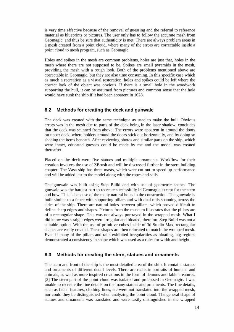
8.2 Methods for creating the deck and gunwale
The deck was created with the same technique as used to make the hull. Obvious
errors was in the mesh due to parts of the deck being in the laser shadow, concludes
that the deck was scanned from above. The errors were apparent in around the doors
on upper deck, where holders around the doors stick out horizontally, and by doing so
shading the items beneath. After reviewing photos and similar parts on the ship, which
were intact, educated guesses could be made by me and the model was created
thereafter.
Placed on the deck were five statues and multiple ornaments. Workflow for their
creation involves the use of ZBrush and will be discussed further in the stern building
chapter. The Vasa ship has three masts, which were cut out to speed up performance
and will be added last to the model along with the ropes and sails.
The gunwale was built using Step Build and with use of geometric shapes. The
gunwale was the hardest part to recreate successfully in Geomagic except for the stern
and bow. This is because of the many natural holes in the construction. The gunwale is
built similar to a fence with supporting pillars and with dual rails spanning across the
sides of the ship. There are natural holes between pillars, which proved difficult to
define sharp edges and shapes. Pictures from the museum illustrates that the pillars are
of a rectangular shape. This was not always portrayed in the wrapped mesh. What I
did know was straight edges were irregular and bloated, therefore Step Build was not a
suitable option. With the use of primitive cubes inside of 3d Studio Max, rectangular
shapes are easily created. These shapes are then relocated to match the wrapped mesh.
Even if many of the pillars and rails exhibited irregularities as bloating, big regions
demonstrated a consistency in shape which was used as a ruler for width and height.
8.3 Methods for creating the stern, statues and ornaments
The stern and front of the ship is the most detailed area of the ship. It contains statues
and ornaments of different detail levels. There are realistic portraits of humans and
animals, as well as more inspired creations in the form of demons and fable creatures.
[2] The stern part of the point cloud was isolated and processed in Geomagic. I was
unable to recreate the fine details on the many statues and ornaments. The fine details,
such as facial features, clothing lines, etc were not translated into the wrapped mesh,
nor could they be distinguished when analyzing the point cloud. The general shape of
statues and ornaments was translated and were easily distinguished in the wrapped

15
mesh. The building supporting the stern was created using Step Build as in the
previous part of the ship.
The statues and ornaments were created using two techniques. There are small statues
of men holding weapons and musical instruments along the sided of the stern around
the small towers, as well as the outer part of the stern, shown in Figure 5.
Figure 5. Pysical Model at the Vasa Museum
Figure 6. Picture of the stern of the Vasa Ship
These statues were too small to be able to recreate within Geomagic with any
definition. There was enough resolution to accurately determine the position of each
statue. Height and width of each statue was harder to determine. Many of the statues
had been damaged over time. Parts that were sticking out from the statues, such as
arms and weapons have been lost in many cases in the restoration process.

16
The larger statues representing knights, smaller head sculptures and the long
ornament/statues along the sides shown in Figure 6 were modeled directly in ZBrush.
The same Geomagic mesh of the whole stern was imported into ZBrush. ZSpheres
were appended as subtools. [6] ZBrush is primarely a sculpting tool, used to create
displacement maps and normal maps. ZBrush works by letting the user work with a
mesh as if it was digital clay. It is created by utilizing pixel technology. [6] ZBrush is
not primarily used to create a base mesh. Meshes from other 3D software are imported
and digitally sculpted within ZBrush. It is used for fine details, however with
ZSpheres, the option to create a mesh from start exist. ZSpheres can be extruded to
form any shape. ZSpheres were used to generally cover the statues. The ZSpheres
were then converted into a mesh and sculpted and can be seen in Figure 7 and Figure
8. The high resolution mesh from Geomagic was used as reference to obtain the mesh
to cover the original statue as correctly as possible.
Figure 7. Black area is a sculpted ZSphere matched to the high resolution mesh.
Figure 8. ZSphere being fitted to the high resolution mesh.
As mentioned before no details were transferred to the wrapped mesh from Geomagic.
These details were sculpted by hand using pictures from the museum. Pictures of the
original ship, as well as the 1:10 scale physical model displayed at the museum were
used. [40]

17
The smaller statues seen in Figure 5 where modeled by first creating the general
shapes out of primitive (polygon cubes etc). The high-resolution mesh was also used
as a reference. The different parts are closely matched to their counterparts on the
high-resolution mesh from Geomagic. When all the different parts are in place, they
are imported into ZBrush for sculpting. Sculpting is based as before on pictures from
the actual Vasa ship and the physical model on display at the museum. Weapons and
other utilities were added to statues later. These were made with the help of standard
primitives.
8.4 Methods for modeling the bow
As with the previous parts of the ship, an appropriate part of the point cloud
containing the bow was cut out and meshed in Geomagic. The Geomagic mesh was
then imported in to 3d Studio Max. The bow also includes ornaments and statues. The
supporting beams and general construction was modeled using the Step Build
function. The statues and ornaments were created using the same methods as
explained in the stern chapter. The bow did propose different problems. There were
not enough points to provide a definite representation of the top part of the bow shown
in Figure 9.
Figure 9. Hard to determine details.
These parts were also created using Step Build, however they are based on pictures
from the museums physical model and the actual ship. There were clues in the
Geomagic mesh to the original construction but nothing conclusive.
8.5 Methods for modeling the masts
As in the other parts of the ship, the first step was to cut out an appropriate part of the
point cloud, create the mesh in Geomagic and import it into 3d Studio Max. Step
Build was not used. Primitive cylinders were created and matched to the imported
Geomagic mesh. The mast that was captured in with the point cloud is not the actual
size of the real mast. Measurements from the museum were used to determine and
model the real height of the mast.

18
8.6 Adding details with textures
All texture work was accomplished with Autodesk Maya. The Vasa ship is mainly
composed of wood material. Wood has a complex structure, veins and scratches that
cannot be modeled by hand. These fine details are added with the help of normal
maps. The colors of the ship are determined by the pysical model and pictures from
the Vasa museum. [5]
8.7 Method analysis of models
The final methods, based on using meshes, were produced hastily in Geomagic and
then re-meshed in 3d Studio Max, which proved to be an effective method. It was
effective concerning time, and when it came to realistically representing the real Vasa
ship in a 3D environment. The 3D models different parts are correctly represented, as
well as the size and height of the ship is also realistically represented.
The topology of the final 3D mesh is also in good order and easy to oversee, and
rebuild if necessary. The imported meshes from Geomagic are triangulated and hard to
oversee, as well as the manual modeling operations on them are time consuming.
8.8 Resembling model and rendering
All parts that were created with Step Build inside of 3D Studio Max and sculpted
items from ZBrush were imported into an empty scene inside of Autodesk Maya.
Inside of Maya, all texture work was completed. The final scene of the model will also
be rendered inside of Autodesk Maya with Mental ray. Figures 10, 11 and 12 shows
the end result.
Figure 10. Final 3D model

19
Figure 11. Final 3D model
Figure12. Final 3D model

20
9.0 Discussion
In this section, I will discuss my research questions. The final method applied to create
a 3D model of the Vasa ship is discussed in correlation with the main goals of this
project.
9.1 A mesh for 3D software
Is it at all possible to obtain a mesh that is usable in a 3D software program for
animating, using an automatic approach? In this case it was not possible to achieve
this because of the lack of resolution in the point cloud on vital parts as the stern and
bow. Parts of the ship could successfully be created automatically within Geomagic,
and with extended post processing the parts would be usable for a realistic model of
the ship as she appears today. Part of the visual reconstruction is to colorize the ship
after the museums guidelines. Having a complicated mesh containing thousands of
triangles would complicate the whole process. Lack of important details translated in
the automatically meshed surface negated the use of remaining working parts.
Successfully, automatically meshed parts were the simplest parts of the ship, regarding
shape. These parts could within a reasonable timeframe be recreated within 3D Studio
Max. Because of this process the manual model consist of a topology which better
suited texture manipulation and it consist of fewer polygons. These factors lead me to
conclude that in this case with provided point cloud that it was not possible to create a
suitable mesh usable for animation. This is because too many details would have to be
left out if I would have only relied on the automatic approach.
Figure 13. Details with 1,940,003 Triangles

21
Figure 14. Details with 484,999 Triangles
Figure 15. Details with15,242,498 Triangles
In Figure 13, the lack of details can be seen on the left side of the picture. Figure 13
consist of 1,940,003 triangles, and Figure 14 shows the same object reduced to
484,999 triangles. When this object was reduced further as shown in Figure 15
triangles are becoming apparent in the picture, as well as a noticeable reduction in
definition. If the object was reduced to the level showed in Figure 15 which is 248,498
triangles the object would have to be smoothed to be able to remove some of the
artifacts and noticeable triangles in the picture. My whole model made by hand using
the high resolution model as a direct reference consist of 788,123 triangles when
needed parts are smoothed, in other words at its highest polygon count. As showed
above to use between 300-500 thousand triangles to represent such a small part of the
ship is a waste of computer power. If more details could be derived from the point
cloud even higher triangles amounts would be needed to represent all the details. The
model produced during this project have the same, and in some cases, better quality of
details because of the workflow applied to recreate all the details that were not
apparent in the point cloud. It still uses less triangles than what the whole model
automated in Geomagic would.
Polygon numbers affected my system less than expected, and with correlation with
Gemoagic‟s decimation algorithm, a model would have been able to produce it
automatically suitable for animation. However, the model would have to be
considered for different situations to effectively answer the question. The automatic
created model would be heavier than the manual; by heavier it would use more
polygons and therefore more computing power from the computer. It would not be

22
farfetched to assume that an animation of the Vasa ship would involve water. Water is
demanding in animation software, and an unnecessary heavy model of the ship would
not be beneficial. Sailors, canons and more details on deck would be needed for a
realistic visualization of the ship. Among the sailors were warriors with armor and
weapons with different clothes and belongings etc. Combined in a huge scene with all
these different parts would raise the polygon count further and increase rendering
time.
It is beneficial if all objects only use the absolute minimum amount of polygons to
successfully represent the intended object. A reason for using more polygons than
necessary would be if quality could be preserved and time of production could be
shortened. This was not the case for this research project. Production time would have
been shorter if I would have relied on automatic mesh creation entirely. However,
quality would not be sufficient enough to realistically represent the Vasa ship as it
appears before it sank.
High polygon numbers can be worked around. Scenes may be divided into smaller
pieces and rendered out individually. These scenes can then be put together in
compositing software. However, this requires additional programs and management.
Regardless, this would not be a valid option in this project, due to lack of resolution in
the automatically created mesh.
9.2 Effective workflow method
The final method explaining the workflow proved to be the most effective method.
The use of Geomagic proved to be extremely helpful. A workflow that only utilized
the point cloud for reference would have been slower. This is because of the increased
control steps necessary to control if the final model is coherent with the boundaries of
the point cloud. There are possibilities to split the model and point cloud up to smaller
pieces to provide a better understanding of the different parts. The hull which
consisted of a fairly simple shape, with many flat areas could easily be modeled with
the point cloud in 3D Studio Max as only reference, and reasonable good time.
However, more complex areas as the bow and stern would have been time
consuming. A Test that was performed on the stern showed that when using only the
point cloud, there were problems defining details and I needed to rely heavily on
reference pictures. And in doing so, many of the ships actual details were lost. Final
scenes in 3d Studio Max 2012, including the hull, bow and deck and supporting
Geomagic meshes, contained 23,037,463 polygons. This is the total number of
polygons in the scene. During work no more than two million polygons are visible on
the screen, to speed up performance. With the use of meshes generated from the point
cloud inside of 3d Studio Max and using the explained method, I found a good balance
between speed, quality and usability. With the use of Step Build, I could remain in
control of topology while I easily and effective could recreate the original shape of the
Vasa ship. The quality is better than the imported mesh from Geomagic, no holes, and
smooth areas only where they are expected. And the quality is high in the sense that
the modeled model inside of 3d Studio Max is coherent with the real Vasa ship in size
and appearance.
9.3 Artistic and manual approach
My first tries to recreate an automatic mesh with the help of VRmesh proved difficult.
The produced mesh could not unify normals without destroying large parts of the

23
mesh that could not be recreated to its former appearance. Definition was lost and
unified normals are also important for Step Build to work inside of 3D Studio Max.
Step Build works by inserting a point on the side of the target mesh based in the
normal direction. If the whole mesh has unified normal‟s but faced in the wrong
direction, it needs to reverse the direction in both 3D Studio Max and VRmesh.
However if they are split up in a chess pattern over the mesh, each normal have to be
reversed individually.
When using Geomagic program, the normal problems disappear. The wrap algorithm
used in Geomagic seemed to unify normals without problems. I have only used
Geomagic for a couple of weeks; however I can clearly see its potential. It has the
ability to successfully reduce triangle count up to 50-70% without detail reduction on
simpler areas. The fact that I could not represent any fine details from the point cloud
on any part of the ship is due to point cloud and its resolution, not the method. Vasa is
a beautiful ship with many fine details, items such as statues and ornaments which is
not scanned with enough resolution to successfully transfer to the wrapped mesh
inside of Geomagic.
The goal of the model is to represent the ship as it once appeared before she sank.
With this in mind, a total recreation of the model inside of 3d Studio Max is justified.
When recreating the ship inside of 3D Studio Max the final mesh consist of primary
quadrants, this helps when texturing and creating areas that are destroyed or changed
during the ships time underwater. However, utilizing the final method and a denser
point cloud would have been preferable and would have beneficial during the detail
work on the bow and stern.
The topology of the final 3D mesh is also in satisfactory and easy to oversee, and
recreate if necessary. The imported meshes from Geomagic are triangulated and hard
to oversee, and the manual modeling operations on them are time consuming. And in
this case, a more manual and artistic approach was not only valid but necessary.
However, the help from an automatic method proved to be time effective.
9.4 Details with automatic mesh creation
Without a point cloud the fine details would have to be created using pictures as the
only reference. This method has the ability to produce satisfactory results. However,
there is a matter of real sizes and coherency between parts. The result is based on
eyesight, or if possible measurements created either on the object or from a secondary
source. The method which I used applying ZBrush and 3D Studio Max was the most
effective and accurate method. The many statues and ornaments were sculpted by
hand, and cannot be 100% accurate to the real life statues.
A much better result would have been possible if it would have been possible to
extract more details from the point cloud in the meshing process inside of the
Geomagic program. Pictures from the real Vasa ship illustrates that many of the
statues and ornaments are damaged and preservation substance on the ship which
provides it a black appearance makes it hard to determine details. Sculpting details by
hand also takes up many man-hours, and in this case, the sheer amount of details and
lack of time provided no choice but to stick to a proven technique. It would not be
possible without automatic mesh creation in this case. No tries were made to recreate
any of the fine details without the automatic mesh as reference. This is because of how
valuable it proved to be as a reference. I would not have been able to finish the project
on time without it. Therefore, I cannot answer this question out of personal knowledge
from this particular project.
24
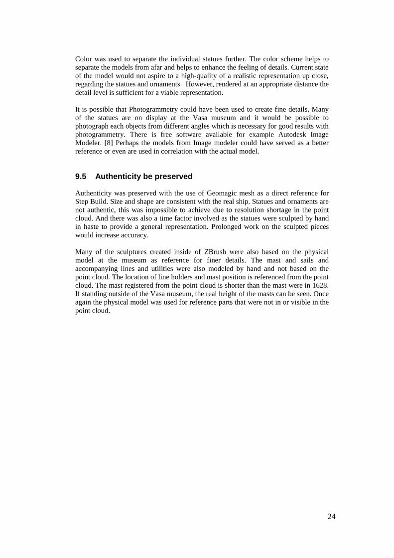
Color was used to separate the individual statues further. The color scheme helps to
separate the models from afar and helps to enhance the feeling of details. Current state
of the model would not aspire to a high-quality of a realistic representation up close,
regarding the statues and ornaments. However, rendered at an appropriate distance the
detail level is sufficient for a viable representation.
It is possible that Photogrammetry could have been used to create fine details. Many
of the statues are on display at the Vasa museum and it would be possible to
photograph each objects from different angles which is necessary for good results with
photogrammetry. There is free software available for example Autodesk Image
Modeler. [8] Perhaps the models from Image modeler could have served as a better
reference or even are used in correlation with the actual model.
9.5 Authenticity be preserved
Authenticity was preserved with the use of Geomagic mesh as a direct reference for
Step Build. Size and shape are consistent with the real ship. Statues and ornaments are
not authentic, this was impossible to achieve due to resolution shortage in the point
cloud. And there was also a time factor involved as the statues were sculpted by hand
in haste to provide a general representation. Prolonged work on the sculpted pieces
would increase accuracy.
Many of the sculptures created inside of ZBrush were also based on the physical
model at the museum as reference for finer details. The mast and sails and
accompanying lines and utilities were also modeled by hand and not based on the
point cloud. The location of line holders and mast position is referenced from the point
cloud. The mast registered from the point cloud is shorter than the mast were in 1628.
If standing outside of the Vasa museum, the real height of the masts can be seen. Once
again the physical model was used for reference parts that were not in or visible in the
point cloud.

25
10.0 Conclusion
I was not able to create a 3D model from the provided point cloud. Too many parts
lacked in details to be realistically visualized. The tests that were completed also
showed that there was an unnecessary overuse of polygons. The method explained in
this report allowed the user to keep all necessary details; however the user can create a
3D model that is more optimized for animation and use in 3D software, such as
Autodesk Maya or 3D Studio Max. The final model consist of only 788,123 triangles,
which is shown in Figure 14, the automatic workflow used 484,999 triangles to
visualize a few meters of the whole ship. Additional optimization steps could have
been applied to the automatic mesh to further reduce the polygon count. Figure 15
showed that the lowest number was around 248,498 triangles before the quality
became too low even for the hull.
The whole ship would also have to contain higher polygon numbers to be able to
retain all the details. In this case that option was not available, because of lacking
details in the point cloud. Nevertheless, the workflow presented here would be usable
in all workflows where the goal is to provide a 3D model from a point cloud. The
techniques ability to recreate a realistic surface and use a lesser amount of polygons
makes it a suitable method for use in the modeling face. That is if the end goal is to
use the model in an animation. The downside with using this technique is that it takes
more time than to recreate a mesh automatically. If the other manual methods are
considered, using the point cloud importer or any other form of visualizing only the
points as reference. The presented method in this project is more effective and more
accurate. Final render times were 8-12 minutes per frame of the final model on my
system.
Authenticity and realism of the object was preserved by using parts of the Geomagic
high resolution mesh as a direct reference inside of 3D Studio Max and Autodesk
Maya. The only human errors that could be made under this project were during the
creation of all the details, statues and ornaments. Steps were taken to minimize these
errors. Closely examining pictures from the museum and also using the Geomagic
mesh once again to be as accurate in placement of statues and ornaments as possible.
Color information and the look of each individual statue were derived by using
information from the museum.
The fine details on the ship where made with the help of Zbrush. The Geomagic mesh
was applied as a direct reference to assure that the statues and ornaments where placed
at the right position. With the help of the Geomagic mesh height and width of the
statues and ornaments could also be established as well as the overall proportions.
Reference pictures where use extensively to complement the Geomagic mesh. A
further improvement in the creation of the statues and ornaments would be to use a
point cloud with a higher resolution, or with the help of photogrammetry.
The overall process allowed the user, in a reasonable time, to create a more polygon
efficient 3D model; efficient in the sense that it used a lesser amount of polygons and
the polygons were more strategically based where they were needed. The
automatically process tend to overuse polygons where they are not needed; the method
presented here does not. The final 3D model created during this project is also
intended for animation and to create visually appealing pictures. However with the use
of this method, 3D models could be created that are intended for use within a game
engine, where restrictions on polygon use are very important.

26
11.1 Future Development
Future development should focus on improving details. With the foundation created,
additional options open up. There are ongoing projects at the Vasa museum with the
goal of scanning all the statues and ornaments. These models could be combined with
my 3D model. Because of the workflow utilized as well as the 3D model is created
from a point cloud, any additional scanned object will fit into the model without the
need for additional editing. Combining different models can cause problems with the
scale factor. However, it can easily be avoided in this case because of the real life
measurements that have been applied in the 3D model creation. Items inside of the
Vasa ship also need to be modeled. This can be accomplished with the same technique
as the other parts of the ship presented during this project. With a complete model of
the Vasa ship various educational animations may be created. The different pieces
from Geomagic can be combined to a 3D model and drawings could be derived from
them.
Due to the composition of salt and fresh water in the Baltic sea, the Vasa ship is well
preserved. Vasa today contains of 98% of the same wood as she did before she sank.
[40] A model of Vasa as she looks today can serve a purpose, extracting drawings for
example. However, a 3D model that presents the ship in her prime also serves a
purpose. A visit to museum combined with an animation may leave the visitor with a
broader and more versatile understanding of the time and the ships that sailed the
Baltic sea or aspired to do so, during the 17th century.

27
References
1. N. D'Apuzzo (2006) "Overview of 3D surface digitization technologies in Europe"
Corner B.D. Li P. Tocheri M. (Eds.), Three-Dimensional Image Capture and
Applications VI, proc. off SPIE-IS&T Electronic Imaging, SPIE Vol. 6056, San Jose
(CA), USA.
2. W. Boehler, G.Heinz, A.Marbs (2002) "The potential of non-contact close range laser scanners
for cultural heritage recording" XVIII. CIPA Symposium, Potsdam, Germany, Proceedings
3. Autodesk 3D Studio Max, http://usa.autodesk.com/3ds-max/ ,(2011-05-30)
4 Autodesk Maya, http://usa.autodesk.com/maya/, (2011-05-30)
5. The Vasa museum,
http://www.vasamuseet.se/, (2011-05-30)
6. Pixologic ZBrush.
http://www.pixologic.com/home.php , (2011-05-30)
7. Autodesk Mudbox,
http://usa.autodesk.com/adsk/servlet/pc/index?id=13565063&siteID=123112
(2011-05-30)
8. Autodeks image modeler,
http://usa.autodesk.com/adsk/servlet/pc/index?id=11390028&siteID=123112
(2011-05-30)
9. A.Hertzmann. (1999) "Introduction to 3D Non-Photorealistic Rendering: Silhouettes and
Outlines" SIGGRAPH 99 Course Notes
10. M.Pharr , P.Hanrahan.( 1996) "Geometry caching for ray tracingdisplacement maps".
In Xavier Pueyo and Peter Schro¨der, editors, Eurographics Workshop on Rendering, pages
31–40
11. Polyworks,
http://www.innovmetric.com/polyworks/3D-scanners/home.aspx?lang=en (2011-05-30)
12. C. Nothegger, P. Dorninger (2007) "Automated modeling of surface detail from point
clouds of historical objects" International CIPA Symposium, 01-06-07 October, Athens,
Greece
13. F. Bernardini, H.Rushmeier(2002) "The 3D Model Acquisition Pipeline"
COMPUTER GRAPHICS forum, Volume 21 (2002), number 2 pp. 149–172
14. C.Altuntas, F.Yildiz, A.Goktepe, H.Karabork (2010) "A study on measurement of
building wall thickness from 3D object model" International Journal of the Physical
Sciences Vol. 5(15), pp. 2317-2321, 18 November
15. D. Barber, J Mills, P. Bryan (2001) “Laser Scanning and Photogrammetry: 21st century
metrology” CIPA Symposium, Potsdam, Germany 2001

28
16. J-P. Pernot, G. Moraru, P. Véron (2007) "Repairing triangle meshes built from scanned
point cloud" Journal of Engineering Design Vol. 18, No. 5, October 2007, 459–473
17. Seok -il, Rixie Li (2006), "complete 3d surface reconstruction from unstructured point
cloud". Journal of mechanical science and technology
Volume 20, Number 12
18. Wenqiang Hu, Wenyu Yang, Youlun Xiong (2005) " An adaptive mesh model for 3D
reconstruction from unorganized data points" Int J Adv Manuf Technol (2005) 26:
1362–1369
19. Agostinho de Medeiros Brito Júnior, Adrião Duarte Dória Neto, Jorge Dantas de Melo,
and Luiz Marcos Garcia Gonçalves (2008) "An Adaptive Learning Approach for 3-D
Surface Reconstruction From Point Clouds" - IEEE Transactions on neural networks,
vol.19, June 2008, pp.1130-1140.
20. H. Hoppe(1994) “Surface reconstruction from unorganized points” Ph.D.
dissertation, Dept. Comput. Sci. Eng., Univ.Washington, Seattle,WA,
1994
21. N. Amenta, S. Choi, and R. K. Kolluri (2001) “The power crust”
in Proc. 6th ACM Symp. Solid Model. Appl., 2001, pp. 249–266.
22. D. Terzopoulos and A. Witkin(1988) “Deformable models,” IEEE Comput.
Graph. Appl., vol. 8, no. 6, pp. 41–51, Nov. 1988.
23. L. D. Cohen(1991) “On active contour models and balloons” (1991) Comput. Vis.
Graph. Image Process.: Image Understanding, vol. 2, no. 53, pp.211–218, 1991.
24. H. Edelsbrunner and E. P. Mücke (1994) "Three-dimensional
alpha shapes" ACM Transactions on Graphics, 13(1):43–72, January, 1994.
25. H. Edelsbrunner(1996) "Surface reconstruction by wrapping
finite sets in space". In Technical Report 96-001. Raindrop Geomagic Inc., 1996.
26. G. Turk and M. Levoy(1994) " Zippered polygon meshes
from range images". In A. Glassner (ed), Proceedings of SIGGRAPH 94, Computer
Graphics Proceedings, Annual Conference Series. pp. 311–318. July, 1994.
27. M. Soucy and D. Laurendeau(1995) "A general surface
approach to the integration of a set of range views". IEEE Transactions on Pattern
Analysis and Machine Intelligence, 17(4):344–358, April, 1995.
28. B. Curless and M. Levoy(1996) "A volumetric method for building complex models from
range images". In Proceedings of SIGGRAPH 96, ACM SIGGRAPH,
Computer Graphics Proceedings, Annual Conference Series. pp. 303–312. August,
1996.
29. M. Wheeler, Y. Sato and K. Ikeuchi(1998) "Consensus surfaces for modeling 3D objects
from multiple range images" In Sixth International Conference on Computer Vision,
IEEE. pp. 917–924. 1998.
30. A. Hilton, A. Stoddart, J. Illingworth and T. Windeatt(1996)
"Reliable surface reconstruction from multiple range images" In Fourth European
Conference on Computer Vision, pp. 117–126. 1996.
31. W. Lorensen and H. Cline(1987) "Marching cubes: a high resolution 3D surface
construction algorithm". Computer Graphics, 21(4):163–170, 1987.

29
32. A. Pentland and S. E. Sclaroff (1991) "Closed form solutions for physically based shape
modelling and recovery". IEEE Transactions on Pattern Analysis and Machine
Intelligence, 13(7):715–729, 1991.
33. D. Terzopoulos, A. Witkin and M. Kass (1988)
"Constraints on deformable models: recovering 3D shape and nonrigid motion".
Artificial Intelligence, 36:91–123, 1988.
34 D. L. Esme, A. Bucksch, W. H. Beekman (2009) " Three-Dimensional Laser Imaging as
a Valuable Tool for Specifying Changes in Breast Shape After Augmentation
Mammaplasty", Aesth Plast Surg (2009) 33:191–195
35 . N.Yastikli (2007) "Documentation of cultural heritage using digital photogrammetry
and laser scanning". Journal of Cultural Heritage 2007;8(4):423�7.
36. Beraldin, J.-A., Picard, M., El-Hakim, S., Godin, G., Valzano,
V., Bandiera, A., and Latouche, C. (2002)
"Virtualizing a Byzantine crypt by combining high-resolution textures with laser scanner 3D
data". In Proceedings of the 8th International Conference on Virtual Systems and Multimedia, 3
–14.
37. El-Hakim, S. F., Beraldin, J.-A., Gonzo, L., Whiting, E., Jemtrud, M, and Valzano, V.
( 2005) "A hierarchical 3D reconstruction approach for documenting complex heritage
sites" CIPA XX International Symposium, Torino. Pages: 790-5
38. Georgopoulos, A., Modatsos, M (2002) "Non-metric bird’s eye view", Proc. ISPRS
Comm. V Symp., Corfu, pp. 359-362.
39. Levo y, M., Pulli, K., Curless, B., Rusinkiewicz, S., Koller, D., Pereira, L., Ginzton, M.,
Anderson, S., Davis, J., Ginsberg, J., Shade, J., Fulk, D (2000)
„„The Digital Michelangelo Project: 3D scanning of large statues,‟‟
Proc. SIGGRAPH 2000, ACM, 2000.
40. The Vasa museum , http://www.vasamuseet.se/sv/Skeppet/
(2011-05-30)
41. The Vasa museum, http://www.vasamuseet.se/sv/Utstallningar/Makten-och-harligheten/'
(2011-05-30)
42. .ply importer for Autodesk Maya http://graphics.stanford.edu/data/3Dscanrep/,
(2011-05-30)
43. Pointtools http://www.pointools.com/, (2011-05-30)
44. Vrmesh http://www.vrmesh.com/, (2011-05-30)
45. Point cloud importer for 3ds max http://labs.autodesk.com/utilities/3dsmax_pointcloud/
46. Retopology example, http://www.youtube.com/watch?v=HZvhZ1OwuFk,
(2011-05-30)
47. Geomagic software, http://www.geomagic.com/en/
(2011-05-30)
48. Geomagic 10 point to mesh workflow,
http://www.geomagic.com/en/techpublications/onlinehelp/studio11/WIZARDSmenu/Po
ints_to_Polygons.htm, (2011-05-31)

30

31
Appendix 1: Script
1. Point cloud importer for 3d studio max. http://labs.autodesk.com/utilities/3dsmax_pointcloud/

32
Appendix 2: Visimind AB and Kungliga tekniska högskolan Delivery report
Kopia av sid 3,8 och 10 från rapporten " Visimind AB and Kungliga tekniska högskolan
Delivery report" / cop. Visimind AB
Publicerad efter muntligt tillstånd av Krzysztof Gajdamowicz, Visimind AB, 2011-09-
26
33

34

35