Modeling Behavior with UML Interactions and Statecharts
117
Page 1 Modeling Behavior with UML Interactions and Statecharts Bruce Powel Douglass, Ph.D. Chief Evangelist I-Logix, Inc. www.ilogix.com UML is a trademark or registered trademark of Object Management Group, Inc. in the U.S. and other countries.
Transcript of Modeling Behavior with UML Interactions and Statecharts

Page 1
Modeling Behavior with UML Interactions and Statecharts
Bruce Powel Douglass, Ph.D.Chief Evangelist
I-Logix, Inc.www.ilogix.com
UML is a trademark or registered trademark of Object Management Group, Inc. in the U.S. and other countries.

Page 2
About the Author• Chief Evangelist for I-Logix•Author of
• Real-Time UML 2nd Edition: Efficient Objects for Embedded Systems (Addison-Wesley, Dec. 1999)• Doing Hard Time: Developing Real-Time Systems with UML, Objects, Frameworks, and Patterns (Addison-Wesley, 1999)• Real-Time Design Patterns: Robust Scalable Architectures for Real-Time Systems (Addison-Wesley, 2002)
• Advisory Board• Embedded Systems Conference • UML World Conference• Software Development Magazine
•Co-chair of OMG RTAD Work Group
Page 3
Agenda
• Basic Behavioral Concepts• Interactions
– Semantics of Interactions– Sequence Diagrams– Collaboration Diagrams– Using Interactions
• Statecharts– Semantics of Statecharts– Statechart Notation– Activity Diagrams– Using Statecharts
Page 4
Basic Behavioral Concepts

Page 5
What IS Behavior?
• Behavior is a change in condition or value over time– May be in response to an event or
request– May be externally visible or not

Page 6
What kinds of things have Behavior?
• Classifiers– Big Objects
• Systems• Subsystems• Components
– Small Objects• “primitive” or “semantic” objects
– Use Cases• Collaborations
– Collaborations are groups of objects working together for a common behavioral purpose
• E.g. realize a use case

Page 7
Types of Behavior• Behavior can be simple
Simple behavior does not depend on the object’s history
• Behavior can be continuousContinuous behavior depends on the object’s history but in a smooth, continuous fashion
• Behavior can be statefulState-driven behavior means that the object’s behavior can be divided into disjoint sets

Page 8
Simple Behavior
• The behavior is not affected by the object’s history– cos( x )– getTemperature( )– setVoltage( v )– max(a,b)–
• May be decomposed arbitrarily deeply into subpart behaviors
∫ −b
a
x dxe2

Page 9
Continuous Behavior• Object’s behavior depends on history in a
continuous way. It does the same kind of behavior but resulting values vary depending on object history
– Control loops
– digital filter
– fuzzy logicUses partial set membership to compute a smooth, continuous output
f d d d dj
j j j j= + + +− − −1 2 3
4
KaXn Yn
-+ DelayWn
Kb
++VnZn

Page 10
State Behavior• Behavior depends on the history of the
object, but in a discrete way• Object does different kinds of behavior and
accepts different events in different states– When aircraft is on the ground, landing gear
cannot be withdrawn– When aircraft is ascending, landing gear cannot
be lowered– When aircraft is descending, landing gear cannot
be raised– When aircraft is in cruise, landing gear can
neither be raised nor lowered

Page 11
Piece-wise Continuous
• A combination of state and continuous– Eg cublic splines
• Performs same actions but results vary depending on object history
State 1 State 2 State 3

Page 12
Behavioral Synchronization• BS applies to how elements synchronize with
respect to the invocation of services during an interaction
• Types– Synchronous
• Sender blocks and waits until Receiver is done– Asynchronous
• Sender “sends and continues”• Receive processes when it is ready

Page 13
Behavior the Single Thread• Single threaded behavior is EASY

Page 14
Behavior and Multiple Threads• Independent multithread behavior is
EASY
Page 15
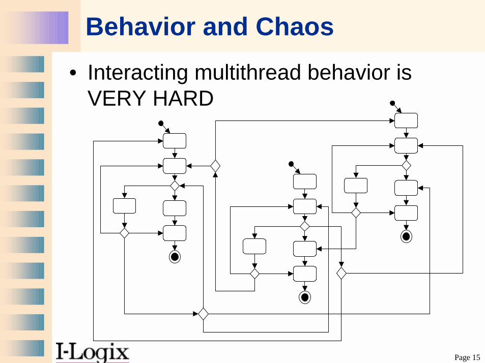
Behavior and Chaos• Interacting multithread behavior is
VERY HARD

Page 16
Problems with Interacting Threads
• Protection of data and resource integrity in the presence contention– No problem with multiple readers– With >= 1 modifier and other accessors,
the data may be corrupted or bad values may be returned
• Deadlock– Happens when a resource client waits for
a condition that can never happen

Page 17
Resource Contention Solutions
• Make resources reentrant– Difficult when modifying or updating a
resource• Serialize access
– Critical section• Disables task switching during resource
access– Mutual exclusion semaphores
• Implies priority inversion– Asynchronous rendezvous
• Implies queuing (queue access must also be protected)

Page 18
Deadlock Prerequisites• ALL of the following are required to have
deadlock:– Mutual exclusion (locking) of resources– Resources are held (locked) while others are
waited for– Preemption while holding resources is permitted– A circular wait condition exists (P1 waits on P2
which waits on P3 which waits on P1). • Liveness can be assured by breaking any of
the above required conditions

Page 19
Deadlock
Legend:Priority: Task 1 > Task 2A: Task 2 runs with the intent of locking R1 then R2B: Task 2 locks R1 and is about to lock R2, when...C: Task 1 runs, prempting Task 2, with the intent of locking R2 then R1D: Task 2 locks R2.E: Now Task 2 needs to lock R1, however R1 is already locked. So Task 2 must block untilTask 1 can release R1. However, Task 1 cannot run to release R1 because it needs R2which is locked by Task 2.
Time
R2
Task 1
0 20 40 60 80 100 120 140 160 180 200 220 240
Active
Inactive
Blocked
R1
Available
Locked
Active
Inactive
Blocked
A
B
C
Available
Locked
Task 2
E
D
R2:Resource
Task 1 Task 2
R1:Resource
1
1 1
1
1
1
1
1
1
1
Adapted from Real-Time Design Patterns by Bruce Powel Douglass Addison-Wesley, 2002

Page 20
(some) Deadlock Solutions
• Critical Sections – Don’t allow other tasks to run while resources are
locked• Simultaneous Locking
– Don’t wait while for other resources• Ordered Locking
– Require locking to take place in a particular order (break circular waiting)
• Priority Ceiling Protocol– Don’t allow locking of low priority resources if a
higher priority resource is held
Page 21
Timing and performance• In real-time systems, we must understand
the Qualities of Service provided by the behavior– Worst case execution time– Average case execution time– Memory requirements– Write access time vs read access time
• We do this by attaching constraints to the behavioral elements– Actions (on statecharts)– Methods
Page 22
Interactions
Page 23
Interaction
• A collection of communications between instances, including all ways to affect instances, – Operation invocation, – Instance creation – Instance destruction
• May be synchronous, asynchronous, or a mixture
• Communications are partially ordered in time

Page 24
UML Interaction Concepts• Instance
– An object• Link
– A run-time connection allowing communication• Action
– Specification of an executable statement• Stimulus
– Communication between two instances

Page 25
UML Interaction Concepts• Operation
– Specification of a requestable service provided by an instance
• Method– Implementation of an operation
• Call– Specification of a synchronous communciation
• Signal– Specification of an asynchronous communication
• Event– An occurrence of interest that results in a signal or
operation call

Page 26
Stimulus Specification• Simple
• With Sequence #– Dotted number
indicates nested call
• With Thread ID
• With Guards and Predecessors
1.4 goto(x,y,z)
goto(x,y,z)
1.4 newPos = goto(x,y,z)
TaskA:1.4 newPos = goto(x,y,z)
TaskB:2.3 TaskA/1.4 newPos = goto(x,y,z)
TaskB2.3/ TaskA: 1.4 [x^2 > y^2+z^2] newPos = goto(x,y,z)

Page 27
Interaction Notations in UML• Sequence diagram
– Most common– Emphasizes sequence over
collaboration structure• Collaboration diagram
– Less common– Emphasizes collaboration structure over
sequence

Page 28
Sequence Diagrams• Sequence diagrams show the
behavior of a group of instances over time. Instances may be– Objects (most common)– Use case instance– System– Subsystem– Actor

Page 29
Sequence Diagrams good for…
• Useful for– Capturing typical or exceptional
interactions for requirements– Understanding collaborative behavior– Demonstrating that collaboration
realizes use case properly– Testing collaborative behavior

Page 30
Sequence DiagramsInstance lifeline
stimulus
Collaboration boundary
description
Time constraint
Partition line
Page 31
SDs for Use Case Details
• Capture interactions of System (or the use case) under consideration and actors
• Used in a “black box” manner• Show typical and exceptional scenarios
of use case, one scenaro per sequence diagram
• Commonly a dozen to several dozen scenarios per use case

Page 32
Use case Example
Page 33
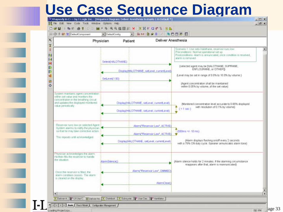
Use Case Sequence Diagram

Page 34
UC Sequence Diagram (detail)
Page 35
Use Case realization• Use cases are realized by collaborations
of instances• How do you connect the use case
sequence diagram to the collaboration?– How do you show it is CORRECT?
• ANS: Execute Elaborated Scenarios– ADD collaboration details and show the
SAME set of scenarios with this new detail– Demonstrate via execution the behavior is
consistent with the required behavior

Page 36
Use Case Collaboration

Page 37
Use Case Realization

Page 38
Use Case Realization (detail)

Page 39
Special Case: Activations• Activations are useful for the
sequential message exchanges
activation
return
stimulus

Page 40
Partial Ordering• Objects are normally assumed to be potentially
concurrent with other objects and so SDs only specify partial order

Page 41
Rules of (partial) Order• Message events (send or receive) on the same lifeline are fully
ordered• Msg.send event precedes Msg.receive event for each message• All other orders are indeterminate

Page 42
Sequence Diagrams and States
• States can be shown on sequence diagrams. The states holds in time until a change of state occurs
• Shows to correspondence between interaction and instance state change
State

Page 43
Deriving Test Vectors from Scenarios
• A scenario is an example execution of a system• A test vector is an example execution of a
system with a known expected result• Scenario ! Test Vector
– Capture preconditions– Determine test procedure
• Identify causal messages and events• Instrument test fixtures to insert causal messages
– Remove optional or “incidental” messages– Define pass/fail criteria
• Identify effect messages / states• Postconditions • Required QoS

Page 44
Stimulating the System
Test Environment or user plays the “Collaboration
Boundary”
Test Environment binds actual instances to instance parameters
as necessary
Test Environment binds actual values to passed operation parameters as
necessary

Page 45
Collaboration Diagrams
• “Approximately isomorphic” to sequence diagrams
• Show basically same things • Emphasize object structure over
sequence• Not as commonly used as sequence
diagrams
Page 46
Collaboration Diagrams• Basically, an object diagram showing
– Instances – Links– Messages with sequence numbers
• Caveat– Sequence is more difficult to follow– You may have to maintain numbers manually
(tool dependent)• Solution
– Use sequence diagrams to show scenario– Use class & object diagrams to show structure
when necessary

Page 47
Collaboration Diagrams
Page 48
Statecharts

Page 49
Finite State Machines
• A finite state model is the description from which any number of instances can be made
• A finite state machine (FSM) is an object which has state behavior defined by– A finite set of states– A finite set of transitions
• So,– What’s a state?– What’s a transition?

Page 50
Statecharts
• What’s a state?
• What’s a transition?
A state is a distinguishable, disjoint, orthogonal ontological condition of
an objects that persists for a significant period of time
A transition is a responseto an event of interest moving
the object from one stateto another

Page 51
Statecharts
• What’s an action?
• What’s the order of action execution?
An action is a run-to-completion behavior. The object will not accept
or process any new events untilthe actions associated with the
current event are complete.
(1)exit actions of current state(2) transition actions
(3) entry actions of next state

Page 52
Example States: Switch
• State: Off• State: On

Page 53
Example States: Oregon Weather
• State: Raining• State: Going to Rain

Page 54
Sample Transition: Elevator

Page 55
Actions• Actions run to completion
– normally actions take an insignificant amount of time to perform
– they may be interrupted by another thread execution, but that object will complete its action list before doing anything else
• Actions are implemented via – an object’s operations– externally available functions– Simple statements (e.g. “x += c*sqrt(d)”)
• They may occur when– A transition is taken– A state is entered– A state is exited

Page 56
Actions
• Assign to a state when they are alwaysexecuted on state entry or exit
• Assign to transition when they they are not always executed on state entry or exit

Page 57
Activities• Activities are behaviors that are executed as
long as an object is in the state• Activities are not run-to-completion
– They may be interrupted by an incoming event• Indicated using
– “do / <activity-list>”– “throughout / <activity-list>”
• Examples– Iterating a trajectory solution– Summing values– NOT “polling a port” since that is a periodic activity

Page 58
A Simple FSM
• You are implementing a reliable transmission service for an OSI-compliant protocol stack.
• A message is sent that requires the receiver to return an ACK.
• If an ACK does not occur, retransmit the message
• If the message is transmitted 5 times without an ACK, then inform the sender.

Page 59
What’s the Object?
reactive object

Page 60
Message Transaction FSM

Page 61
Harel Statecharts• Created by David Harel of I-Logix in late
1980s• Forms the basis for the behavioral model of
the Unified Modeling Language• Supports
– Nested states– Actions and Activities– Guards– History– Broadcast Events– Orthogonal Regions (AND-States)

Page 62
Basic Syntax 1
B
T1(int r)[r < 0] / f(r)
event name
guard
action list
state
A
entry / g(x), h(y)exit / m(a), n(b)do / act(a,y,z)defer / e1, e2e3 / p(x,y), q(z)
event parameters
entry actions
exit actions
activities
deferred events
internal transition
state name

Page 63
Transitions: Sending Events
• Comma separated list of transitions that occur in other concurrent state machines because of this transition
• A.k.a propagated events
tm(eventTime) / target -> genSignal(evClockTick)

Page 64
Transitions: Guards
• A guard is some condition that must be met for the transition to be taken
• Guards can be– Variable range specification– Concurrent state machine is in some state
[IN(X)]– Some other constraint (preconditional
invariant) must be met
Page 65
Handling Transitions• If an object is in a state S that responds to a
named event E, it will act on it– Transition to the specified state if
• the event triggers a named transition and• the guard on the transition (if any) evaluates to TRUE• Includes executing transition actions and propagating
specified events
– Handle the event without changing state if the event triggers a named reaction
• Includes executing action list associated with reaction
– Defer the event if in a defer clause

Page 66
Handling Transitions• Events are quietly discarded if
– A transition is triggered but the transition’s guard evaluates to FALSE
– A transition to a conditional pseudostate is triggered but all exiting transition guards evaluate to FALSE
– The event does not explicitly trigger a transition, reaction, or deferment

Page 67
Types of Events• UML defines 4 kinds of events
– Signal Event• Asynchronous signal received• e.g. evFlameOn
– Call Event• operation call received• e.g. op(a,b,c)
– Change Event• change in value occurred
– Time Event• Relative time elapse• Absolute time arrived• e.g. tm(PulseWidthTime)
Page 68
Types of Events• Events are occurrences of interest
that have both– Location– Absolute time of occurrence
• Signal events associate with Signals• A Signal is a specification of an
asynchronous communication between structural elements (e.g. objects)
• One type of Signal is Exception

Page 69
Null-Triggered Transitions
• A.k.a. “Completion Transitions”• Triggered upon completion of
– entry actions, and – any state activities
• May contain a guard condition• Will only be evaluated once, even if
guard condition later becomes true

Page 70
Null-Triggered Transitions
T[g]
E
entry/ F()do/ act()
S
Null-triggered transition trigger immediately upon completion of action
F() and activity act(). If g evaluates to FALSE, then the ONLY WAY it will ever
be evaluated again is if event Eoccurs, retriggering the null-triggered
transition.

Page 71
Basic syntax 2
ev_2
state
nested state
or-states
Page 72
Nested (OR) States• Improves scalability• Increases understandability• Permits problem decomposition
(divide-and conquer)• Methods
– Nested states on same diagram– Nested states on separate diagram
• aka “submachines”

Page 73
Submachines
Has submachine
Referenced submachine

Page 74
Submachines: Referenceand Stubstates
toOn(mode: tMode)defaultMode = mode;
Off
Self Testinginclude / BITSubmachine
RAM Testdevice Test
On
UnrecoverableError
Operatinginclude / OpsSubmachine
Normal Failsafe
toOff errorFoundC
errorHandled
[recoverOK]
[else]Abort
doTest
doRAMtest
doDeviceTest
done(defaultMode)
submachineindicator
stub state reference

Page 75
Submachines: Referenced
TestingROM
TestingRAM
TestingComponents
LoggingTest
Results
BITSubmachine
FailsafeC
Abort
done
done
[else]
[isError == false]
RAMTest
device Test
OpsSubmachine
NormalMode
DemoMode
FailsafeMode
subEnd
C
toOfferrorFound
[m == normal]
[else]
[m == failsafe]
Normal
doTest
doRAMtestdoDeviceTest
errorFound/isError = true;
entry / isError = false;
(m: tMode)
Normal
stub state
submachine

Page 76
Order of Nested Actions• Execute from outermost - in on entry• Execute from innermost - out on exit
U entry: f( )exit: g(a,b)
U1 entry: x(c )exit: y()
A
first f( ) then x(c)
first y( ) then g(a,b )

Page 77
AND-States• States may be decomposed into either
– OR-States• A superstate may be decomposed into any
number of OR-States• When the object is in the superstate, it must be in
exactly one of its OR-substates.– AND-State
• A superstate may be decomposed into any number of AND-States (regions of behavioral independence)
• When in the containing superstate, the object must be in EVERY active AND-substate
• Shown with dashed line• a.k.a “Orthogonal regions”

Page 78
AND-States & Concurrency
• AND-states are not necessarily concurrent in the thread or task sense
• UML uses active objects as the primary means of modeling concurrency
• AND-states may be implemented as concurrent threads, but that is not the only correct implementation strategy

Page 79
Basic syntax 3 and-states
forkjoin

Page 80
AND-State Communication• AND-states may communicate via
– Broadcast events• transitions to the object are received by all active
AND-states– Propagated events
• A transition in one AND-state can send an event that affects another
– Guards• [IS_IN( state )] uses the substate of an AND-state
in a guard– Attributes
• Since the AND-states are of the same object, they “see” all the attributes of the object

Page 81
Basic syntax 4: pseudostates
initialpseudostate history
pseudostate
conditionalpseudostateterminal
pseudostate

Page 82
Pseudostates
T
C
H*
*
or
Symbol Symbol Name
n
or
or
HBranch Pseudostate (type ofjunction pseudostate)
Terminal or Final Pseudostate
Initial or Default Pseudostate
Fork Pseudostate
Join Pseudostate
Junction Pseudostate
(Shallow) History Pseudostate
(Deep) History Pseudostate
Synch Pseudostate
Choice Point Pseudostate
Merge Junction Pseudostate(type of junction pseudostate)[g]
[g]
Symbol Symbol Name
Stub Pseudostatelabel

Page 83
“Synch” Pseudostate
• Allows a special kind of guard in which a “latch” remembers that a specific transition has occurred
• Similar to Petri net “place” with explicitly indicated capacity
• Must synchronize across AND-States

Page 84
dataSignal
Data Processing
AlarmProcessing
Waiting forData
ProcessingDatum
Waiting toProcessAlarms
ApplyingAlarmFilters
DisplayingAlarms
*
tm(displayTime)
Waiting toaccept
done
[active alarm ct > 0]/genSignal(alarmRaised)
[else]
1
LoggingData
C
accept
User Monitoring
/active alarm ct = 0
/active alarm ct = 0
Idle
alarmRaised
Synch Pseudostatewith unboundedmultiplicity
“Synch” Pseudostate
synch state
synch state

Page 85
Inherited State Behavior
• Two approaches to inheritance for generalization of reactive classes– Reuse (i.e. inherit) statecharts of parent– Use custom statecharts for each
subclass• Reuse of statecharts allows
– specialization of existing behaviors– addition of new states and transitions– makes automatic code generation
possible

Page 86
Inherited State Behavior
• Subclasses may be– Specialized
• Statechart specialization– Substates may be added– Transitions may be rerouted– Action lists may be modified
– Extension• Statechart extension
– New states added– New transitions added– New action lists added

Page 87
Inherited State Behavior
• Assumes Liskov Substitution Principle for generalization:A subclass must be freely substitutable for the superclass in any operation
• You CAN– Add new states– Elaborate substates in inherited states– Add new transitions and actions
• You CANNOT– Delete inherited transitions or states

Page 88
Example: Generalization
OffSwitch On /
f( )
Blower
OnSwitch Off
Dual Speed Blower
OffSwitch On /
g( )
Switch Off /h( ),k( )
On
Low
High
toHigh
toLow
Dual Speed MultiHeat Blower
OffSwitch On
Switch Off /k( )
Low
High
toHightoLow
On
Cool
WarmHot
toCool
toWarmtoHot
new substates
modified action list
new transitions
new and-substates
modified action list
modified action list
Base class statechart

Page 89
Ill Formed Statecharts
No default state
Race condition
Race condition
Non-exclusive guards
(attempted) use of side effects of action in guard
e2e2e2e2
e3e3e3e3Must be the same event
into a join

Page 90
Executing Statecharts

Page 91
Balancing Parentheses• Build a machine that can balance arbitrary
parenthetical expressions• Note that no FSM can do this because it requires an
infinite set of states or memory:– ‘(‘ ‘((‘ ‘(((‘ ‘((((‘ are all different conditions
( ( ) ( ) . . . input stream
balancedstate
indicator
FSM
unbalanced

Page 92
Balancing 4 Parentheses
Empty
))( ))
)((
)())()(
)())
)((
)((
)))
))(
))((
))()
)))(
))))
((( ()
(((
(()
((((
((()
(()(
(())
()(
())
()((
()()
())(
()))

Page 93
Balancing Parentheses (with Memory)
• If we add a counting machine (i.e. memory), we can build a simple FSM if we note that are conditions met by all valid expressions states:– The number of characters is even (0, 2, 4, ...)– The number of left parentheses equals the
number of right parentheses– The next token received when the state
corresponds to a balanced expression must be a left parenthesis.

Page 94
Balancing Parentheses (with Memory)

Page 95
Balance ‘( ( ) )’
Current state

Page 96
Balance ‘( ( ) )’
Current state

Page 97
Balance ‘( ( ) )’
Current state

Page 98
Balance ‘( ( ) )’
Current state

Page 99
Example 2: ‘( ) ) ( ) ’
Current state

Page 100
Example 2: ‘( ) ) ( ) ’
Current state

Page 101
Example 2: ‘( ) ) ( ) ’
Current state

Page 102
Dueling Reactive ObjectsObjectSource
OB1 OB2
State1
State1
s /genSignal(T1(17, 3.14159), OB1, OB2)
StateX
StateY
StateW
StateV
T1(a: int, b:float) /c = b^a;
T1(d: int, e:float) /h += d / (e+d);
source source
firstTarget secondTarget11
1 1event multicasting withevent parameters
event reception with parameter
processing
event reception with parameter
processing

Page 103
Example: Jolt Cola Machine Class Diagram

Page 104
Example: Jolt Machine Class Diagram
submachine reference

Page 105
Substate: DispensingCan
submachine statechart
substateconnector

Page 106
Class Button FSM

Page 107
Implementation of statecharts

Page 108
Simple Approach #1 • Use nested CASE statements to implement state
case (state1) {switch(event) {
case e1: ….; break;case e2: ….; break;}
case state2 : switch(event) {….
• Problems– Performance– Scalability– Code bloat with generalization of reactive classes– Not thread safe (need to add mutex semaphore to
protect all event acceptor operations), or serialize via queuing events)

Page 109
Simple Approach #2• Use a single state variable (class attribute)
which holds the current state• Event acceptor operations
– actions of event acceptor operations vary depending on the value of the state variable
– event acceptor operations update this state variable to change state
• Problems– All clients need to know how to call all the
different event acceptors– Scalability– Thread safety (same as approach 1)

Page 110
Simple Approach #2
• ExamplemyClass::AcceptTurn(int nClicks) {
if (stateVar = OPERATIONAL) {display(nClicks);clicks += nClicks;if (clicks > MAX)
stateVar = OVERFLOW;}; // end if
};

Page 111
Approach #3: State Pattern
State Pattern
Context AbstractState
Concrete State
Accept(event)
Current State
Abstract State
ConcreteState
1Context
*
{abstract}

Page 112
Approach #3: State Pattern
• Good when some set of states are long lasting
• Good to optimize rapidly-changing states by making less-frequent state changes more expensive
• Memory impact– Less memory required when statecharts
are inherited– May require additional memory if there is
not much specialization

Page 113
Approach #3: State Pattern«context»Idle Mode
«context»AAI Mode
Turn Oncreate( )
To AAIdestroy( )
create( )
tm(Ref Time)
A Sense accept( A Sense)
Refractory
Waiting
Waiting
tm(A Sense Time)
Pacing
«context»Pacing Engine

Page 114
Approach #4: State Table Pattern
State TablePatternContext
*
State
1
Context
Transition
These dependencies allowtransitions and states to calloperations within Context as
actions.
1
1
StateTable
1
The state table is oriented as astate x transition matrix allowing
access in a single probe«callback»
«callback» *
guardaccept
setDefaultaddGuard
nextState
Transition
entryexit
activity
stateID
State
entryexit
activity
currentState
State TableStateTableTemplate
state space,transition space

Page 115
State Table Pattern
• Good for large state spaces• Good for constant run-time
performance• More complex and expensive to set
up
Detailed C++ code for this pattern can be seen inReal-Time UML 2nd Edition: Developing Efficient Objects forEmbedded Systems, Addison-Wesley, 1999

Page 116
State Table PatterntheContext StateTable State 2
«context» «state»
State 1 Trans 1«transition»«state table» «state»
create<nStates, nTrans>create()
assignState(State 1)
guard( )
accept(event)
create()assignState(State 2) create()
assignTrans(Trans 1)
setDefault(target state, guard, action)
accept(event)
(*guard)()return TRUEexitAction( )(*exitAction)()
accept()(*action)()
entryAction( )(*entryAction)()
return
setDefault(initialState)

Page 117
Some References of Interest
![[fmt.isti.cnr.it]fmt.isti.cnr.it/WEBPAPER/OntestingUMLstatecharts.pdf · The Journal of Logic and Algebraic Programming 69 (2006) 1–74 On testing UML statecharts Mieke Massink,](https://static.fdocuments.net/doc/165x107/5ae6bbeb7f8b9a8b2b8da6c5/fmtisticnritfmtisticnritwebpaperont-journal-of-logic-and-algebraic-programming.jpg)