
Modeling and Simulation of Photoelectrochemical Cells · 2017-01-23 · Modeling and Simulation of...
26
Modeling and Simulation of Photoelectrochemical Cells 4th Wädenswil Day of Chemistry Solar Energy – Chemical Solutions 21. Juni 2012 Dr. Matthias Schmid [email protected]
Transcript of Modeling and Simulation of Photoelectrochemical Cells · 2017-01-23 · Modeling and Simulation of...
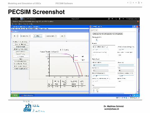
Modeling and Simulation ofPhotoelectrochemical Cells
4th Wädenswil Day of ChemistrySolar Energy – Chemical Solutions21. Juni 2012
Dr. Matthias [email protected]
Introduction
Outline
IntroductionInstitute of Computational Physics (ICP)PEC Research at the ICP
Photoelectrochemical CellsDye-sensitized Solar CellPhotoelectrochemical Water Splitting
Modeling and Simulation of DSCsOptical ModelElectrical ModelPECSIM Software
Conclusions
Dr. Matthias [email protected]
Introduction Institute of Computational Physics (ICP)
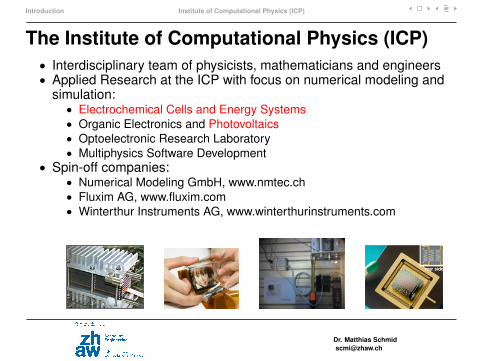
The Institute of Computational Physics (ICP)• Interdisciplinary team of physicists, mathematicians and engineers• Applied Research at the ICP with focus on numerical modeling and
simulation:• Electrochemical Cells and Energy Systems• Organic Electronics and Photovoltaics• Optoelectronic Research Laboratory• Multiphysics Software Development
• Spin-off companies:• Numerical Modeling GmbH, www.nmtec.ch• Fluxim AG, www.fluxim.com• Winterthur Instruments AG, www.winterthurinstruments.com
Dr. Matthias [email protected]
Introduction PEC Research at the ICP
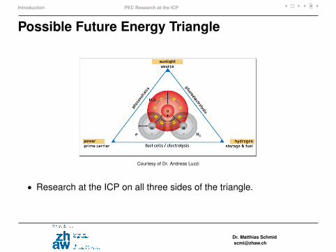
Possible Future Energy Triangle
Courtesy of Dr. Andreas Luzzi
• Research at the ICP on all three sides of the triangle.
Dr. Matthias [email protected]
Introduction PEC Research at the ICP
Photoelectrochemical Cells (PECs)
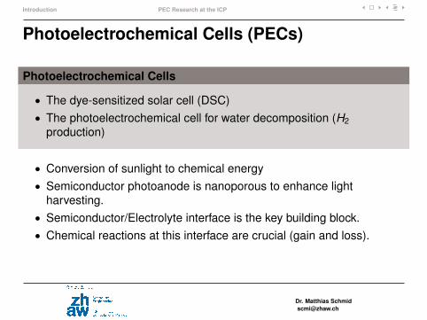
Photoelectrochemical Cells
• The dye-sensitized solar cell (DSC)• The photoelectrochemical cell for water decomposition (H2
production)
• Conversion of sunlight to chemical energy• Semiconductor photoanode is nanoporous to enhance light
harvesting.• Semiconductor/Electrolyte interface is the key building block.• Chemical reactions at this interface are crucial (gain and loss).
Dr. Matthias [email protected]
Introduction PEC Research at the ICP
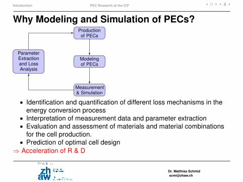
Why Modeling and Simulation of PECs?Productionof PECs
Modelingof PECs
ParameterExtractionand LossAnalysis
Measurement& Simulation
• Identification and quantification of different loss mechanisms in theenergy conversion process
• Interpretation of measurement data and parameter extraction• Evaluation and assessment of materials and material combinations
for the cell production.• Prediction of optimal cell design
⇒ Acceleration of R & D
Dr. Matthias [email protected]
Photoelectrochemical Cells
Outline
IntroductionInstitute of Computational Physics (ICP)PEC Research at the ICP
Photoelectrochemical CellsDye-sensitized Solar CellPhotoelectrochemical Water Splitting
Modeling and Simulation of DSCsOptical ModelElectrical ModelPECSIM Software
Conclusions
Dr. Matthias [email protected]
Photoelectrochemical Cells Dye-sensitized Solar Cell
The Dye-Sensitized Solar Cell (DSC)
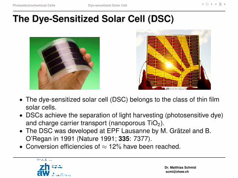
• The dye-sensitized solar cell (DSC) belongs to the class of thin filmsolar cells.
• DSCs achieve the separation of light harvesting (photosensitive dye)and charge carrier transport (nanoporous TiO2).
• The DSC was developed at EPF Lausanne by M. Grätzel and B.O’Regan in 1991 (Nature 1991; 335: 7377).
• Conversion efficiencies of ≈ 12% have been reached.
Dr. Matthias [email protected]
Photoelectrochemical Cells Dye-sensitized Solar Cell
The Dye-Sensitized Solar Cell
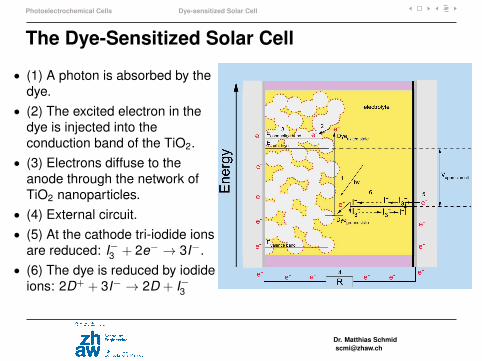
• (1) A photon is absorbed by thedye.
• (2) The excited electron in thedye is injected into theconduction band of the TiO2.
• (3) Electrons diffuse to theanode through the network ofTiO2 nanoparticles.
• (4) External circuit.• (5) At the cathode tri-iodide ions
are reduced: I−3 + 2e− → 3I−.• (6) The dye is reduced by iodide
ions: 2D+ + 3I− → 2D + I−3
Dr. Matthias [email protected]
Photoelectrochemical Cells Photoelectrochemical Water Splitting
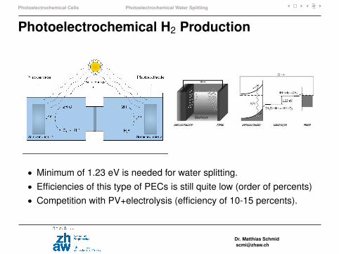
Photoelectrochemical H2 Production
• Minimum of 1.23 eV is needed for water splitting.• Efficiencies of this type of PECs is still quite low (order of percents)• Competition with PV+electrolysis (efficiency of 10-15 percents).
Dr. Matthias [email protected]
Photoelectrochemical Cells Photoelectrochemical Water Splitting
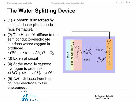
The Water Splitting Device
• (1) A photon is absorbed bysemiconductor photoanode(e.g. hematite).
• (2) The Holes h+ diffuse to thesemiconductor/electrolyteinterface where oxygen isproduced4OH− + 4h+ → 2H2O + O2
• (3) External circuit• (4) At the metallic cathode
hydrogen is produced4H2O + 4e− → 2H2 + 4OH−
• (5) OH− diffuses from thecounter electrode to thephotoanode.
Dr. Matthias [email protected]
Modeling and Simulation of DSCs
Outline
IntroductionInstitute of Computational Physics (ICP)PEC Research at the ICP
Photoelectrochemical CellsDye-sensitized Solar CellPhotoelectrochemical Water Splitting
Modeling and Simulation of DSCsOptical ModelElectrical ModelPECSIM Software
Conclusions
Dr. Matthias [email protected]
Modeling and Simulation of DSCs Optical Model
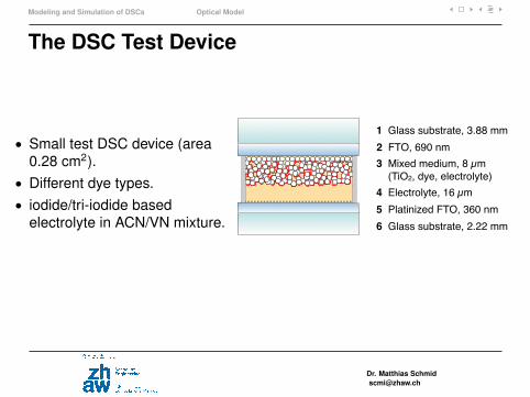
The DSC Test Device
• Small test DSC device (area0.28 cm2).
• Different dye types.• iodide/tri-iodide based
electrolyte in ACN/VN mixture.glass
e
1 Glass substrate, 3.88 mm
2 FTO, 690 nm
3 Mixed medium, 8 µm
(TiO2, dye, electrolyte)
4 Electrolyte, 16 µm
5 Platinized FTO, 360 nm
6 Glass substrate, 2.22 mm
Dr. Matthias [email protected]
Modeling and Simulation of DSCs Optical Model
Optical ModelObjective: Simulate the spatially resolved electron generation rate profileg(x , λ) and the maximum achievable quantum efficiency QEmax(λ).
• The simulations are performed using a ray tracing algorithm andaccounts for multiple internal reflections and absoprtion losses in thecell.
• The optical simulation incorporates coherent (matrix transfer method)and incoherent optics.
• The nanoporous TiO2 layer is treated as an effective medium.• The indices of refraction and extinction coefficients of the materials
are needed as input.• The model is validated by R and T measurements on the complete
device.• g(x , λ) is input for the electrical model.
Dr. Matthias [email protected]
Modeling and Simulation of DSCs Optical Model
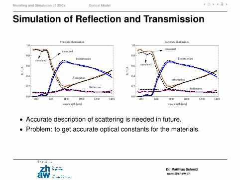
Simulation of Reflection and Transmission
Transmission
Absorption
Reflection
measured
simulated
400 600 800 1000 1200 14000.0
0.2
0.4
0.6
0.8
1.0
wavelength @nmD
R,T
,A
frontside illumination
Reflection
Absorption
Transmission
measured
simulated
400 600 800 1000 1200 14000.0
0.2
0.4
0.6
0.8
1.0
wavelength @nmD
R,T
,A
backside illumination
• Accurate description of scattering is needed in future.• Problem: to get accurate optical constants for the materials.
Dr. Matthias [email protected]

Modeling and Simulation of DSCs Electrical Model
Electrical Model
Objective: Simulate IV characteristic j(V ) and the quantum efficiencyQE(λ).
• The electrochemical potentials (Fermi energy for electrons and redoxenergies for ions) are solutions of a system of coupled non-linearPDEs.
• The electric model accounts for recombination at the TiO2/electrolyteinterface and transport limitations in the TiO2 and the electrolyte.
• Trapping to an exponential distribution of localized band gap states istaken into account using the quasi-static approximation.
Dr. Matthias [email protected]
Modeling and Simulation of DSCs Electrical Model
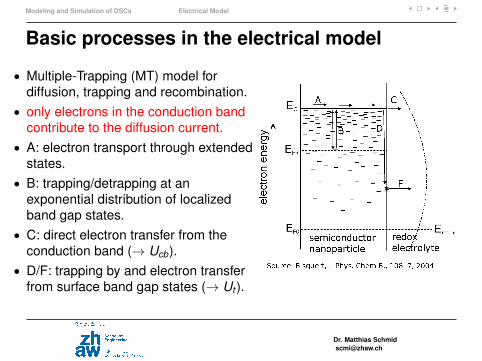
Basic processes in the electrical model
• Multiple-Trapping (MT) model fordiffusion, trapping and recombination.
• only electrons in the conduction bandcontribute to the diffusion current.
• A: electron transport through extendedstates.
• B: trapping/detrapping at anexponential distribution of localizedband gap states.
• C: direct electron transfer from theconduction band (→ Ucb).
• D/F: trapping by and electron transferfrom surface band gap states (→ Ut ).
Dr. Matthias [email protected]
Modeling and Simulation of DSCs Electrical Model
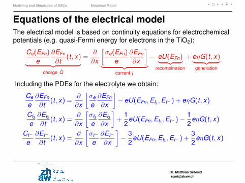
Equations of the electrical modelThe electrical model is based on continuity equations for electrochemicalpotentials (e.g. quasi-Fermi energy for electrons in the TiO2):
Ce(EFn)
e∂EFn
∂t(t , x)︸ ︷︷ ︸
charge Q̇
=∂
∂x
[σe(EFn)
e∂EFn
∂x
]︸ ︷︷ ︸
current j
− eU(EFn)︸ ︷︷ ︸recombination
+eηG(t , x)︸ ︷︷ ︸generation
Including the PDEs for the electrolyte we obtain:
Ce
e∂EFn
∂t(t , x) =
∂
∂x
[σe
e∂EFn
∂x
]− eU(EFn,EI3 ,EI−) + eηG(t , x)
CI3
e∂EI3
∂t(t , x) =
∂
∂x
[σI3
e∂EI3
∂x
]+
12
eU(EFn,EI3 ,EI−)−12
eηG(t , x)
CI−
e∂EI−
∂t(t , x) =
∂
∂x
[σI−
e∂EI−
∂x
]− 3
2eU(EFn,EI3 ,EI−) +
32
eηG(t , x)
Dr. Matthias [email protected]
Modeling and Simulation of DSCs Electrical Model
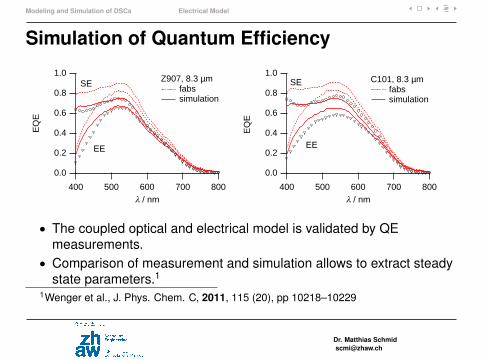
Simulation of Quantum Efficiency
1.0
0.8
0.6
0.4
0.2
0.0
EQ
E
800700600500400l / nm
Z907, 8.3 µm fabs simulation
EE
SE1.0
0.8
0.6
0.4
0.2
0.0
EQ
E
800700600500400l / nm
C101, 8.3 µm fabs simulation
EE
SE
• The coupled optical and electrical model is validated by QEmeasurements.
• Comparison of measurement and simulation allows to extract steadystate parameters.1
1Wenger et al., J. Phys. Chem. C, 2011, 115 (20), pp 10218–10229
Dr. Matthias [email protected]
Modeling and Simulation of DSCs Electrical Model
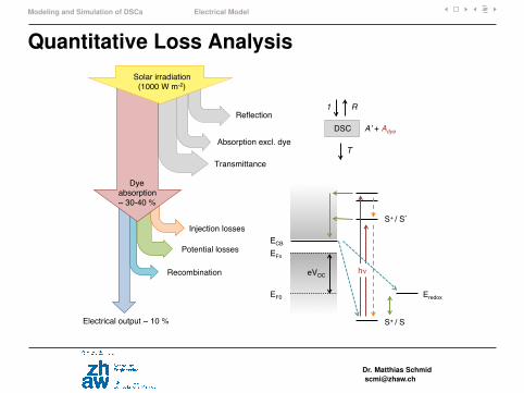
Quantitative Loss Analysis
Reflection!
Absorption excl. dye!
Transmittance!
Dye!absorption!~ 30-40 %!
Injection losses!
Potential losses!
Recombination!
Electrical output ~ 10 %!
DSC!
T!
R!
Aʼ + Adye!
1!
ECB!EFn!
EF0!
S+ / S!
S+ / S* !
Eredox!
hν!
Solar irradiation!(1000 W m-2)!
eVOC!
Dr. Matthias [email protected]
Modeling and Simulation of DSCs Electrical Model
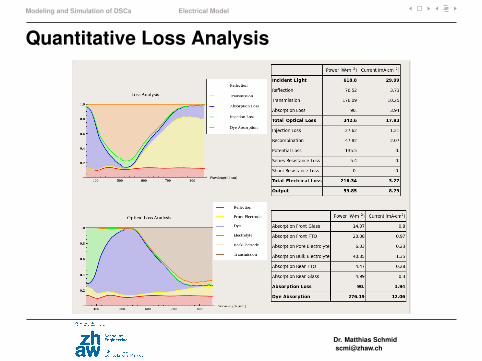
Quantitative Loss Analysis
Dr. Matthias [email protected]
Modeling and Simulation of DSCs PECSIM Software
PECSIM Software
“PECSIM” = Photo-Electro-Chemical SIMulation software
• PECSIM is a simulation software for the systematic model-basedanalysis and optimization of dye-sensitized solar cells (DSCs)
• The software supports R&D on dye-sensitized solar cells.• PECSIM is based on a validaded physical model for DSCs. The
model consists of a coupled optical and electrical model.• The software is equipped with a simple graphical user interface
(GUI).• PECSIM is written in Mathematica language. Either a license of the
Mathematica Player Pro or a full license of Mathematica is needed torun the software.
Dr. Matthias [email protected]
Modeling and Simulation of DSCs PECSIM Software
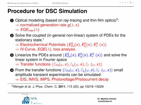
Procedure for DSC Simulation1 Optical modeling (based on ray-tracing and thin-film optics)2:⇒ normalized generation rate g(λ, x)⇒ EQEmax(λ)
2 Solve the coupled (in general non-linear) system of PDEs for thestationary state.1
⇒ Electrochemical Potentials {E0Fn(x),E
0I3(x),E
0I−(x)}
⇒ IV-Curve, EQE(λ), loss analysis3 Linearize the PDEs around {E0
Fn(x),E0I3(x),E
0I−(x)} and solve the
linear system in Fourier space⇒ Transfer functions {ε̂Fn(ω, x), ε̂I3(ω, x), ε̂I−(ω, x)}
4 From the transfer functions {ε̂Fn(ω, x), ε̂I3(ω, x), ε̂I−(ω, x)} smallamplitude transient experiments can be simulated:⇒ EIS, IMVS, IMPS, Photovoltage/Photocurrent decay
2Wenger et al. J. Phys. Chem. C, 2011, 115 (20), pp 10218–10229
Dr. Matthias [email protected]

Conclusions
Outline
IntroductionInstitute of Computational Physics (ICP)PEC Research at the ICP
Photoelectrochemical CellsDye-sensitized Solar CellPhotoelectrochemical Water Splitting
Modeling and Simulation of DSCsOptical ModelElectrical ModelPECSIM Software
Conclusions
Dr. Matthias [email protected]
Conclusions
Conclusions
• Dye-sensitized solar cells and cells for water photodecomposition aretwo kinds of photoelectrochemical cells. They harvest light andconvert its energy to chemical energy.
• Chemical reactions at the semiconductor/electrolyte interface arecrucial for their energy conversion process.
• Photoelectrochemical cells combine optics, nanophysics andelectrochemistry.
• Modeling and Simulation of photoelectrochemical cells is animportant tool to accelerate research and development.
Dr. Matthias [email protected]