Modeling and imaging with isochron rays - Center for Wave
12
CWP-602 Modeling and imaging with isochron rays Eduardo F. F. Silva 1 and Paul Sava 2 1 Petrobras S.A., Rio de Janeiro, Brazil 2 Center for Wave Phenomena, Colorado School of Mines, Golden, CO, USA ABSTRACT Isochron rays are lines perpendicular to isochrons, which represent surfaces of con- stant two-way traveltime. The image of a temporal sequence of seismic impulses is a sequence of isochrons in depth. The later the time impulse the deeper the isochron. The term isochron ray arises from an analogy between the isochron “movement” and the wave propagation. While isochrons behave as wavefronts, its perpendicular lines can be regarded as rays. The speed of the isochron movement depends on the medium velocity and the source-receiver position. We introduce the term equivalent-velocity to refer to the speed of isochron movement. In the particular case of zero-offset data, the equivalent velocity is half of the medium velocity. We use the concepts of isochron- rays and equivalent velocity to extend the application of the exploding reflector model to non-zero offset imaging problems. In particular, we employ these concepts to extend the use of zero-offset wave-equation algorithms for modeling and imaging common- offset sections. In our imaging approach, the common-offset migration is implemented as a trace-by-trace algorithm in three steps: 1) equivalent velocity computation, 2) data-conditioning for zero-offset migration, and 3) zero-offset wave-equation migra- tion. We apply this methodology for modeling and imaging synthetic common-offset sections using two kinds of algorithms: finite-difference and split-step wavefield ex- trapolation. We illustrate the isochron-ray imaging methodology with a field-data ex- ample and compare the results with conventional common-offset Kirchhoff migration. This methodology is attractive because (1) it permits depth migration of common- offset sections or just pieces of that by using wave-equation algorithms, (2) it extends the use of robust zero-offset algorithms, (3) it presents favorable features for paral- lel processing, (4) it permits the creation of hybrid migration algorithms, and (5) it is appropriate for migration velocity analysis. Key words: wave equation, imaging, modeling, isochron, isochron-rays 1 INTRODUCTION Isochron rays are curves associated with propagating isochrons, that is, with surfaces that are related to seismic re- flections with the same two-way traveltime. Isochron surfaces play an important role in seismic imaging because they are closely related to the impulse response of depth migration. Hubral et al. (1996) showed how a weighted Kirchhoff-type isochron-stack integral can be applied to true-amplitude algo- rithms for both modeling and data transformation. The general theory of data mapping, presented by Bleistein et al. (2000), emphasizes the importance of isochrons in the establishment of integral formulas for inversion. Iversen (2004) introduced the term isochron ray for tra- jectories associated with surfaces of equal two-way time, i.e. isochron surfaces, and suggested the potential use of isochron rays in future implementations of prestack depth migration. Here we exploit the idea and present a methodology that makes use of the isochron ray concept to perform prestack depth migration. We consider as isochron rays the curves that are perpendicular to the isochrons associated with the image produced by the migration of a single finite-offset seismic trace. That is, isochron rays are the orthogonal trajectories to isochrons. This concept differs from the one introduced by Iversen (2004), which involves non-orthogonal trajectories. Our imaging approach consists of a trace-by-trace al-
Transcript of Modeling and imaging with isochron rays - Center for Wave
CWP-602
Modeling and imaging with isochron rays
Eduardo F. F. Silva1 and Paul Sava21Petrobras S.A., Rio de Janeiro, Brazil2Center for Wave Phenomena, Colorado School of Mines, Golden, CO, USA
ABSTRACT
Isochron rays are lines perpendicular to isochrons, which represent surfaces of con-stant two-way traveltime. The image of a temporal sequence of seismic impulses is asequence of isochrons in depth. The later the time impulse the deeper the isochron.The term isochron ray arises from an analogy between the isochron “movement” andthe wave propagation. While isochrons behave as wavefronts, its perpendicular linescan be regarded as rays. The speed of the isochron movement depends on the mediumvelocity and the source-receiver position. We introduce the term equivalent-velocity torefer to the speed of isochron movement. In the particular case of zero-offset data, theequivalent velocity is half of the medium velocity. We use the concepts of isochron-rays and equivalent velocity to extend the application of the exploding reflector modelto non-zero offset imaging problems. In particular, we employ these concepts to extendthe use of zero-offset wave-equation algorithms for modeling and imaging common-offset sections. In our imaging approach, the common-offset migration is implementedas a trace-by-trace algorithm in three steps: 1) equivalent velocity computation, 2)data-conditioning for zero-offset migration, and 3) zero-offset wave-equation migra-tion. We apply this methodology for modeling and imaging synthetic common-offsetsections using two kinds of algorithms: finite-difference and split-step wavefield ex-trapolation. We illustrate the isochron-ray imaging methodology with a field-data ex-ample and compare the results with conventional common-offset Kirchhoff migration.This methodology is attractive because (1) it permits depth migration of common-offset sections or just pieces of that by using wave-equation algorithms, (2) it extendsthe use of robust zero-offset algorithms, (3) it presents favorable features for paral-lel processing, (4) it permits the creation of hybrid migration algorithms, and (5) it isappropriate for migration velocity analysis.
Key words: wave equation, imaging, modeling, isochron, isochron-rays
1 INTRODUCTION
Isochron rays are curves associated with propagatingisochrons, that is, with surfaces that are related to seismic re-flections with the same two-way traveltime. Isochron surfacesplay an important role in seismic imaging because they areclosely related to the impulse response of depth migration.Hubral et al. (1996) showed how a weighted Kirchhoff-typeisochron-stack integral can be applied to true-amplitude algo-rithms for both modeling and data transformation. The generaltheory of data mapping, presented by Bleistein et al. (2000),emphasizes the importance of isochrons in the establishmentof integral formulas for inversion.
Iversen (2004) introduced the term isochron ray for tra-jectories associated with surfaces of equal two-way time, i.e.isochron surfaces, and suggested the potential use of isochronrays in future implementations of prestack depth migration.Here we exploit the idea and present a methodology thatmakes use of the isochron ray concept to perform prestackdepth migration. We consider as isochron rays the curves thatare perpendicular to the isochrons associated with the imageproduced by the migration of a single finite-offset seismictrace. That is, isochron rays are the orthogonal trajectories toisochrons. This concept differs from the one introduced byIversen (2004), which involves non-orthogonal trajectories.
Our imaging approach consists of a trace-by-trace al-

194 E.F.F. Silva & P. Sava
gorithm, wherein each finite-offset input trace is first condi-tioned for zero-offset extrapolation and then migrated using anequivalent-velocity model. We present two imaging strategies.In the first approach the prestack depth migration is achievedby performing the downward continuation of the conditioneddata along the isochron rays, followed by the application of thezero-offset imaging condition. The second imaging approachconsists of a reverse-time migration algorithm, where the con-ditioned data is reversed and injected into the equivalent ve-locity model along an isochron defined by the time-shift pre-viously applied on the input trace.
The main purpose of this research is the development ofa methodology to apply zero-offset wave-equation algorithmsto solve finite offset problems. In particular, this methodol-ogy can be useful in the implementation of migration veloc-ity analysis methods based on offset continuation, see Silva(2005). Also, the presented methodology is attractive because(1) it permits depth migration of common-offset gathers usingwave-equation algorithms, (2) it extends the use of robust zero-offset algorithms to the common-offset case, (3) it is based onalgorithms that are appropriate for parallel processing, and (4)it permits to combine different imaging algorithms.
2 THE ISOCHRON RAY CONCEPT
Given a source-receiver pair and a fixed reflection traveltime,the related isochron is the surface that answers the question:Where are the possible reflection points located? In otherwords, an isochron surface is the image of points with thesame reflection time. An isochron surface can be viewed asa hypothetical reflector whose reflections from the source Sare recorded simultaneously at the receiver R. For any pointM belonging to an isochron surface, the traveltime measuredalong the path SMR does not vary.
The isochron surfaces play an important role in seismicimaging, especially in prestack depth migration. For a singletrace composed of a sequence of impulses, the image producedby depth migration is represented by a set of isochrons. Thelonger the reflection time, the greater the distance betweenthe source-receiver pair and the isochron. The shape of theisochrons depends on the velocity field, the reflection time, andthe spatial location of the source and receiver. In a homoge-neous medium, every isochron has an ellipsoidal shape whosefocus points are located at the source and receiver position,while the eccentricity is defined by the seismic wave velocityand the reflection time. The shallowest isochron surface tendsto collapse into a straight line connecting the source-receiverpair.
Consider a sequence of depth migrated images where theinput data consist of a sequence of seismic impulses with vary-ing reflection time. Notice in Figure 1(a) as the impulse timeincreases by the same amount with the first being just littlelonger than the direct arrival traveltime. The initial surface(first isochron) observed in the first image moves in depth,changing its shape and acting as a propagating wavefront. Ifa point of the initial surface is selected and followed duringthe sequence, its trajectory will define a curve. We refer to this
curve as an isochron ray because it acts as a ray, while themoving isochron plays the role of a propagating wavefront.
2. 1 Equivalent velocity media
The propagating isochron ”moves” through the model witha speed that is different from the wave propagation veloc-ity. The isochron propagation velocity depends on the source-receiver location, and the medium velocity and it varies evenin isotropic-homogeneous media.
For a given source-receiver pair, we can imagine a hy-pothetical medium with the velocity distribution identical tothat of the isochron velocity propagation. We refer to this asthe equivalent velocity medium. There are two features thatcharacterize the equivalent velocity field. First, isochron prop-agation velocity depends on the isochron ray direction, whichmeans it can be multivalued in the presence of caustics. Sec-ond, equivalent velocity fields present a singularity in the lineconnecting the source-receiver pair, which corresponds to thehypothetical starting isochron.
Depending on the complexity of the original velocitymodel, we distinguish two cases of determining equivalent ve-locity and isochron ray tracing. One is based on the assump-tion of the absence of caustics, and another is the general case,where no restrictions are imposed on the velocity model.
Let us assume a smooth seismic velocity model with nocaustics. Consider a source-receiver pair located in a horizon-tal plane where the velocity does not vary in a small slabbetween the source and the receiver. In this situation, theisochron-field can be reproduced by a hypothetical experimentwhere the seismic source is a horizontal segment connectingthe source-receiver pair, and the seismic velocity is the equiv-alent velocity medium. All the isochron rays are perpendicularto the line source. In the vertical plane that contains the source-receiver pair, all the isochron rays are vertical at their startingpoint. The isochron rays obey Snell’s law and the wavefrontsare the surfaces of constant traveltime in space satisfying theeikonal equation:„
∂tsr
∂x
«2
+
„∂tsr
∂y
«2
+
„∂tsr
∂z
«2
=1
V 2eq(x, y, z)
. (1)
In the absence of triplications, the equivalent velocitymedium can be directly determined by applying the eikonalequation on the two-way traveltime map. This velocity fieldcan be used to migrate the conditioned data using conventionalzero-offset migration algorithms. In the presence of triplica-tions, equivalent velocity media are multivalued and cannot bederived from traveltime maps. In this case, the isochron prop-agation velocity should be represented in isochron ray coor-dinates and has to be computed using a proper isochron ray-tracing algorithm. Also, the migration should use wave-fieldextrapolation in isochron ray coordinates. This case falls out-side the scope of this paper and remains subject to future re-seach.

Isochron rays 195
Time
Detph
Position
(a)
Position
Time
Depth
(b)Time
Depth
Position
(c)
Figure 1. Propagating isochrons
2. 2 Isochron ray-tracing without media restriction
The isochron propagation can be performed by applying ba-sic principles of wave propagation. For simplicity, consider anisochron in a 2D media. In Figure 2(a), the point M is theintersection of three curves:
• z = ζs(x, S, ts) is the wavefront that comes from thesource position, S = (xs, zs), at the time ts.• z = ζr(x, R, tr) is the wavefront that comes from the
receiver position, R = (xr, zr), at the time tr .• z = ζ(x, S, R, ts + tr) is the isochron corresponding to
the source-receiver pair SR at the two-way traveltime tsr =ts + tr .
Figure 2(b) shows the isochrons after a propagation timeof δt/2, the wavefront z = ζs(x, S, ts) moves to z =ζs(x, S, ts + δt/2), the wavefront z = ζr(x, R, tr) moves toz = ζr(x, R, tr + δt/2), the isochron z = ζ(x, S, R, ts + tr)moves to z = ζ(x, S, R, ts + tr + δt), and the intersectionpoint moves to M ′. In 2D models, the triple intersection pointcan be found by merely locating the intersection between thesource and receiver wavefronts. In this case, an isochron raycan be traced just by mapping the intersection points step bystep.
In the case of 3D, the intersection between the source andreceiver wavefronts is a curve instead of a point. Consequently
the use of the unknown isochron is needed for determiningthe intersection point. The isochron is unknown but it can bedefined as the envelope of intersection lines between sourceand receiver wavefronts whose total traveltime is constant.
2. 3 The exploding reflector model
The exploding reflector model (Lowenthal et al., 1985) iswidely applied in both seismic modeling and imaging algo-rithms. Although it is an approximation that cannot be repro-duced by a physical experiment, it leads to simple, robust andefficient algorithms. Zero-offset seismic data can be modeledand migrated by a large number of approaches, such as Kirch-hoff, finite-differences, and Gaussian beams.
For zero-offset data, the two-way traveltime of primaryreflections with normal-incidence angle can be computed bytracing normal rays in a half-velocity medium.
The isochron-rays play a role analogous to normal rays,i.e., they are perpendicular to the reflectors, and the traveltimemeasured along them is the time on the two-way path: source-reflector-receiver. While the normal rays can be traced usingthe half-velocity medium, the isochron-rays need an equiva-lent velocity medium that depends on the source and receiverlocation. Therefore we need to define an equivalent velocitymedium for each source-receiver pair. Another important dif-

196 E.F.F. Silva & P. Sava
M
ζ
r
ζs
ζ
(a)
M
ζr
ζs
M’
ζ
(b)
Figure 2. Isochron ray-tracing scheme: a) wavefronts at ts and tr , isochron at tr + ts, b) wavefronts at ts + δt/2 and tr + δt/2, isochron attr + ts + δt/2.
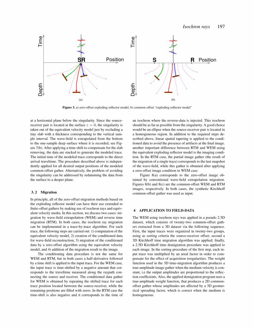
ference between normal and isochron rays is the take-off (oremergence) angle. While normal rays can assume any direc-tion at the recording surface even when the first layer is homo-geneous, the isochron rays are always perpendicular to it, seefigure 3(b). Because of the analogy described above, we sug-gest the expression ”Equivalent exploding reflector model” torefer to the association of isochron rays and equivalent veloc-ity model.
3 IMAGING USING ISOCHRON RAYS
3. 1 Modeling
In this section, we present two examples in which we extendthe use of zero-offset algorithms to finite offset data by ap-plying the concepts of isochron rays, equivalent velocity, andexploding reflector model. We generate three common-offsetsections with the methods: finite-difference, split-step wave-field extrapolation and Kirchhoff. The third dataset was gener-ated by conventional Kirchhoff modeling to be used as bench-mark.
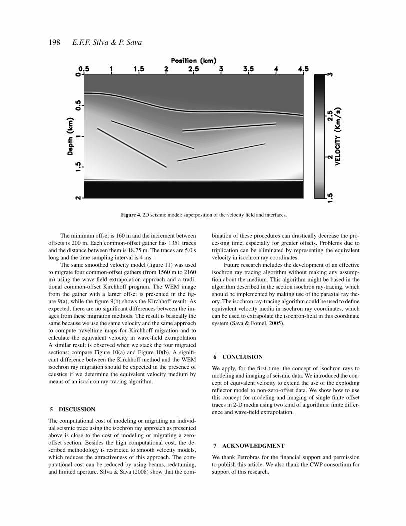
The 2D seismic model consists of six interfaces im-mersed in a smooth velocity field, where the wave velocitypropagation varies from 1500 m/s at the shallow part, to 3000m/s at the bottom. The Figure 4 shows the velocity model andthe interfaces. For all cases, the source-receiver pair is locatedon the horizontal plane at z=0.
For Kirchhoff modeling, a Ricker wavelet with dominantfrequency of 20 Hz was used. The integration was performedusing a spatial interval of 1 m without any special care aboutthe dynamic aspects. Figure 5(a) shows the synthetic Kirch-hoff common-offset section for the half-offset h=500 m.
For both finite-difference and wavefield extrapolationmodeling, the common-offset section was constructed trace-by-trace using an equivalent velocity medium for each CMPposition. The equivalent velocity media were defined follow-ing the steps:
• Build the travel-time map ts(x, z) from the source loca-
tion to all points of the model using an eikonal solver algo-rithm.• Do the same from the receiver location, getting the travel-
time map tr(x, z).• Add the two maps to obtain the two-way travel-time map
tsr = ts + tr .• Find the spatial partial derivatives of the two-way travel-
time (tsr).• Apply the eikonal equation to determine the equivalent
velocity for every grid point.
The equivalent velocity media has a singularity betweenthe source-receiver pair, where the velocity goes to infinity.Thus we need to adopt special procedures to avoid numericalproblems in this region. The applied procedures are differentfor each case. However both are based on an analytical solu-tion for the isochron propagation in the vicinity of the source-receiver pair. In Figure 6 we present the equivalent-velocityfield for the central position of the seismic model presented inFigure 4.
For finite difference modeling, we avoid numerical insta-bility by clipping the equivalent velocity field and placing thereceivers along an isochron located away from the singularity.A good choice for locating this recording isochron is a regionwhere the wave propagation is constant because it is an ellipsein this case.
The recorded isochron-field contains information fromall directions, but only information that travels along isochronrays should be considered. In other words, we have to sum theamplitudes along isochrons, which is equivalent to a stack ofthe information collected in the recording isochron along thetime. Figure 5(b) is the common-offset gather modeled by thefinite-difference approach. Each trace of this gather is the re-sult of the stacking of all traces recorded along an isochronwhose midpoint between the source and receiver correspondsto the trace location. Figure 7(a) corresponds to the seismo-gram recorded at the central position of the seismic model.
For modeling by wave-field extrapolation, the adoptedprocedure consists of recording the wave-field (isochron-field)
Isochron rays 197
Depth
Time
PositionSR
(a)
Position
Time
Depth
S R
(b)
Figure 3. a) zero-offset exploding reflector model, b) common-offset “exploding reflector model”
at a horizontal plane below the singularity. Since the source-receiver pair is located at the surface z = 0, the singularity istaken out of the equivalent velocity model just by excluding atiny slab with a thickness corresponding to the vertical sam-ple interval. The wave-field is extrapolated from the bottomto the one-sample deep surface where it is recorded, see Fig-ure 7(b). After applying a time-shift to compensate for the slabremoving, the data are stacked to generate the modeled trace.The initial time of the modeled trace corresponds to the directarrival traveltime. The procedure described above is indepen-dently applied for all desired output positions of the modeledcommon-offset gather. Alternatively, the problem of avoidingthe singularity can be addressed by redatuming the data fromthe surface to a deeper plane.
3. 2 Migration
In principle, all of the zero-offset migration methods based onthe exploding reflector model can have their use extended tofinite-offset gathers by making use of isochron rays and equiv-alent velocity media. In this section, we discuss two cases: mi-gration by wave-field extrapolation (WEM) and reverse timemigration (RTM). In both cases, the isochron ray migrationcan be implemented in a trace-by-trace algorithm. For eachtrace, the following steps are carried out: 1) computation of theequivalent velocity model, 2) creation of the conditioned datafor wave-field reconstruction, 3) migration of the conditioneddata by a zero-offset algorithm using the equivalent velocitymodel, and 4) addition of the migration result to the image.
The conditioning data procedure is not the same forWEM and RTM, but in both cases a half-derivative followedby a time shift is applied to the input trace. For the WEM case,the input trace is time-shifted by a negative amount that cor-responds to the traveltime measured along the raypath con-necting the source and receiver. The conditioned data gatherfor WEM is obtained by repeating the shifted trace for eachtrace position located between the source-receiver, while theremaining positions are filled with zeros. In the RTM case thetime-shift is also negative and it corresponds to the time of
an isochron where the reverse-data is injected. This isochronshould be as far as possible from the singularity. A good choicewould be an ellipse when the source-receiver pair is located ina homogeneous region. In addition to the required steps de-scribed above, linear spatial tapering is applied to the condi-tioned data to avoid the presence of artifacts at the final image.another important difference between RTM and WEM usingthe equivalent exploding reflector model is the imaging condi-tion. In the RTM case, the partial image gather (the result ofthe migration of a single trace) corresponds to the last snapshotof the wave-field, while this gather is obtained after applyinga zero-offset image condition in WEM case.
Figure 8(a) corresponds to the zero-offset image ob-tained by conventional wave-field extrapolation migration.Figures 8(b) and 8(c) are the common-offset WEM and RTMimages, respectively. In both cases, the synthetic Kirchhoffcommon-offset gather was used as input.
4 APPLICATION TO FIELD-DATA
The WEM using isochron rays was applied in a pseudo 2.5Ddataset, which consists of twenty-two common-offset gath-ers extracted from a 3D dataset via the following sequence.First, the input traces were organized in twenty-two groups,using as sorting criteria the source-receiver offset; second a3D Kirchhoff time migration algorithm was applied; finally,a 2.5D Kirchhoff time demigration procedure was applied toeach image. In the sorting procedure of the first step, each in-put trace was multiplied by an areal factor in order to com-pensate for the effect of acquisition irregularities. The weightfunction used in the 3D time-migration algorithm produces atrue-amplitude image gather when the medium velocity is con-stant, i.e the output amplitudes are proportional to the reflec-tion coefficients. Also, the applied demigration program uses atrue-amplitude weight function, that produces a 2D common-offset gather whose amplitudes are affected by a 3D geomet-rical spreading factor, which is correct when the medium ishomogeneous.
198 E.F.F. Silva & P. Sava
Figure 4. 2D seismic model: superposition of the velocity field and interfaces.
The minimum offset is 160 m and the increment betweenoffsets is 200 m. Each common-offset gather has 1351 tracesand the distance between them is 18.75 m. The traces are 5.0 slong and the time sampling interval is 4 ms.
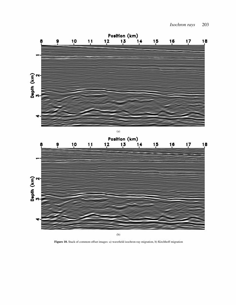
The same smoothed velocity model (figure 11) was usedto migrate four common-offset gathers (from 1560 m to 2160m) using the wave-field extrapolation approach and a tradi-tional common-offset Kirchhoff program. The WEM imagefrom the gather with a larger offset is presented in the fig-ure 9(a), while the figure 9(b) shows the Kirchhoff result. Asexpected, there are no significant differences between the im-ages from these migration methods. The result is basically thesame because we use the same velocity and the same approachto compute traveltime maps for Kirchhoff migration and tocalculate the equivalent velocity in wave-field extrapolationA similar result is observed when we stack the four migratedsections: compare Figure 10(a) and Figure 10(b). A signifi-cant difference between the Kirchhoff method and the WEMisochron ray migration should be expected in the presence ofcaustics if we determine the equivalent velocity medium bymeans of an isochron ray-tracing algorithm.
5 DISCUSSION
The computational cost of modeling or migrating an individ-ual seismic trace using the isochron ray approach as presentedabove is close to the cost of modeling or migrating a zero-offset section. Besides the high computational cost, the de-scribed methodology is restricted to smooth velocity models,which reduces the attractiveness of this approach. The com-putational cost can be reduced by using beams, redatuming,and limited aperture. Silva & Sava (2008) show that the com-
bination of these procedures can drastically decrease the pro-cessing time, especially for greater offsets. Problems due totriplication can be eliminated by representing the equivalentvelocity in isochron ray coordinates.
Future research includes the development of an effectiveisochron ray tracing algorithm without making any assump-tion about the medium. This algorithm might be based in thealgorithm described in the section isochron ray-tracing, whichshould be implemented by making use of the paraxial ray the-ory. The isochron ray-tracing algorithm could be used to defineequivalent velocity media in isochron ray coordinates, whichcan be used to extrapolate the isochron-field in this coordinatesystem (Sava & Fomel, 2005).
6 CONCLUSION
We apply, for the first time, the concept of isochron rays tomodeling and imaging of seismic data. We introduced the con-cept of equivalent velocity to extend the use of the explodingreflector model to non-zero-offset data. We show how to usethis concept for modeling and imaging of single finite-offsettraces in 2-D media using two kind of algorithms: finite differ-ence and wave-field extrapolation.
7 ACKNOWLEDGMENT
We thank Petrobras for the financial support and permissionto publish this article. We also thank the CWP consortium forsupport of this research.

Isochron rays 199
(a) (b) (c)
Figure 5. Common-offset gathers: a) Conventional Kirchhoff modeling, b) isochron-ray finite-difference modeling, and c) isochron-ray wavefieldextrapolation modeling.
REFERENCES
Bleistein, N., Cohen, J. K., and Stockwell, J., 2000, Mathe-matics of multidimensional seismic imaging, migration andinversion: , number 13, Interdisciplinary applied mathemat-ics.
Hubral, P., Schleicher, J., and Tygel, M., 1996, A unified ap-proach to 3-D seismic reflection imaging, part I: Basic con-cepts: Geophysics, 61, no. 03, 742–758.
Iversen, E., 2004, The isochron ray in seismic modeling andimaging: Geophysics, 69, no. 4, 1053–1070.
Lowenthal, D., Lu, L., Roberson, R., and Sherwood, J. W. C.,1985, The wave equation applied to migration in Gardner,G. H. F., Ed., Migration of seismic data:: Soc. of Expl. Geo-phys., 208–227.
Sava, P., and Fomel, S., 2005, Riemannian wavefield extrap-olation: Geophysics, 70, no. 03, T45–T56.
Silva, E. F. F., and Sava, P., 2008, Accelerating wavefield ex-trapolation isochron-ray migration:.
Silva, E. F. F., 2005, Horizon velocity analysis using ocorays: Horizon velocity analysis using oco rays:, SBGf, 9thCongress of The Brazilian Society of Geophysics, Salvador,Brazil.

200 E.F.F. Silva & P. Sava
Figure 6. Equivalent velocity for the central position of the seismic model clipped at 4,5 m/s.
(a) (b)
Figure 7. a) Finite-difference recorded isochron field, b) Extrapolated isochron field recorded at z = 0.005km

Isochron rays 201
(a)
(b)
(c)
Figure 8. a) Zero-offset wave-field extrapolation migration, b) Common-offset wave-field extrapolation migration, c) Common-offset reverse timemigration,

202 E.F.F. Silva & P. Sava
(a)
(b)
Figure 9. Common-offset images: a) wavefield isochron-ray migration, b) Kirchhoff migration
Isochron rays 203
(a)
(b)
Figure 10. Stack of common-offset images: a) wavefield isochron-ray migration, b) Kirchhoff migration

204 E.F.F. Silva & P. Sava
Figure 11. Velocity model for the field-data example