Modeling and Design of the Wireless Controlled Self ...
13
Modeling and Design of the Wireless Controlled Self-Driving Security System Using In-Wheel Drives Jongnam Bae, Seungjun Kim, Dong-Hee Lee * Mechatronics Engineering, Kyungsung University and South Korea, Busan, South Korea. * Corresponding author. Tel.: +8251-663-4693; email: [email protected] Manuscript submitted November 12, 2018; accepted February 25, 2019. doi: 10.17706/ijcee.2019.11.2.78-90 Abstract: This paper presents a modeling and design of the wireless controlled self-driving security system using in-wheel drives. The designed system has the wireless main controller, sensor boards, HD-camera, up-down control board and two in-wheel drives to control the In-wheel BLDC(Brushless DC) motor. Each board is connected by the serial communication and the main controller is wireless connected to the remote controller. Key words: Self-driving, security system, wireless controlled, serial communication connected, in-wheel drives, BLDC (Brushless DC) motor. 1. Introduction Self-driving system is much interested in the logistics, information guide, entertainments and security system [1]-[7]. In the security system, high quality image of HD-camera which is installed on the self-driving security vehicle is wireless transferred to the remote controller. The remote controller can analyze and monitor the image from the moving security vehicle by the dip learning algorithm. For the moving security system, the rail guided system, line tracer system and self-driving system can be adopted [8]. The rail guided moving system is very useful in the indoor environment. And the moving vehicle can follow the rail surface by the reference position. Although, the rail guided system is very effective in the moving security system, it is very difficult to be adopted in the outdoor environment due to the rail guide installation problem The image based security system which is self-driving consists of complex components such as three actuactors (wheel drives, HD-camera up-down mover, HD-camera rotating actuator), four sensor boards (front, rear, left and right side) and HD-camera. For the stable moving and control of the self-driving security system, all complex components are tightly connected by the serial communication. For the distributed control of HD-camera moving and the vehicle body moving, the main controller has to connect and distribute the target reference to each component. Furthermore, the main controller has to be wireless connected to the remote controller in the monitoring room [9]-[13]. The line tracer system is another choice for the moving security system. However, the tracking line has to be clearly displayed to detect the moving trajectory of the security vehicle. Furthermore, the blind spot far from the tracking line cannot be monitored by the moving security system. In this paper, the first proto-type and the advanced designed system for the self-driving security vehicle are presented. The detailed mechanical and electrical configurations are explained. The key features and International Journal of Computer Electrical Engineering 78 Volume 11, Number 2, June 2019
Transcript of Modeling and Design of the Wireless Controlled Self ...
Modeling and Design of the Wireless Controlled Self-Driving Security System Using In-Wheel Drives
Jongnam Bae, Seungjun Kim, Dong-Hee Lee*
Mechatronics Engineering, Kyungsung University and South Korea, Busan, South Korea. * Corresponding author. Tel.: +8251-663-4693; email: [email protected] Manuscript submitted November 12, 2018; accepted February 25, 2019. doi: 10.17706/ijcee.2019.11.2.78-90
Abstract: This paper presents a modeling and design of the wireless controlled self-driving security system
using in-wheel drives. The designed system has the wireless main controller, sensor boards, HD-camera,
up-down control board and two in-wheel drives to control the In-wheel BLDC(Brushless DC) motor. Each
board is connected by the serial communication and the main controller is wireless connected to the
remote controller.
Key words: Self-driving, security system, wireless controlled, serial communication connected, in-wheel drives, BLDC (Brushless DC) motor.
1. Introduction
Self-driving system is much interested in the logistics, information guide, entertainments and security
system [1]-[7]. In the security system, high quality image of HD-camera which is installed on the self-driving
security vehicle is wireless transferred to the remote controller. The remote controller can analyze and
monitor the image from the moving security vehicle by the dip learning algorithm.
For the moving security system, the rail guided system, line tracer system and self-driving system can be
adopted [8]. The rail guided moving system is very useful in the indoor environment. And the moving
vehicle can follow the rail surface by the reference position. Although, the rail guided system is very
effective in the moving security system, it is very difficult to be adopted in the outdoor environment due to
the rail guide installation problem
The image based security system which is self-driving consists of complex components such as three
actuactors (wheel drives, HD-camera up-down mover, HD-camera rotating actuator), four sensor boards
(front, rear, left and right side) and HD-camera. For the stable moving and control of the self-driving
security system, all complex components are tightly connected by the serial communication. For the
distributed control of HD-camera moving and the vehicle body moving, the main controller has to connect
and distribute the target reference to each component. Furthermore, the main controller has to be wireless
connected to the remote controller in the monitoring room [9]-[13].
The line tracer system is another choice for the moving security system. However, the tracking line has to
be clearly displayed to detect the moving trajectory of the security vehicle. Furthermore, the blind spot far
from the tracking line cannot be monitored by the moving security system.
In this paper, the first proto-type and the advanced designed system for the self-driving security vehicle
are presented. The detailed mechanical and electrical configurations are explained. The key features and
International Journal of Computer Electrical Engineering
78 Volume 11, Number 2, June 2019
problems in the first proto-type system which has four wheels and motor drives connecting by the serial
communication are described in this paper. In order to solve the presented problem, the modified
self-driving security vehicle which has two-wheel system is proposed.
The proposed two-wheel based integrated twin controller is simulated and tested to verify the firmware
and the moving performance. In the simulation, the estimated moving angle can be derived by the gyro and
acceleration signals by the designed complementary filter. And, the speed compensator can make the
compensation speed reference to reduce the moving angle error. The compared results, the designed
system can reduce the tracking error. In the experiments, the effectiveness of the proposed system is
verified by the tracking performance.
2. 4-Wheel System and Practical Problems
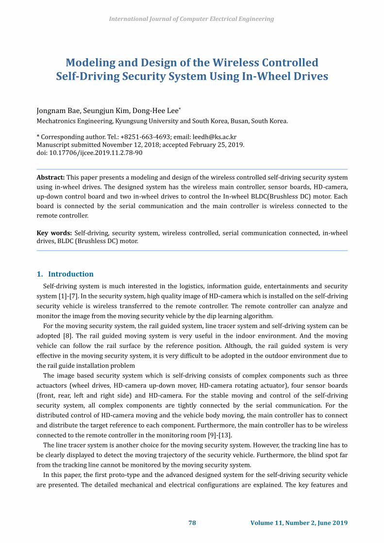
Fig. 1 shows the designed the first proto-type self-driving security system. As shown in Fig. 1, the
designed first proto-type self-driving security system has 4 wheels in the body and one up-down mover for
the HD-camera. In the outside of the moving body, ultra-sonic and infrared sensors are installed to detect
the obstacles during the self-driving. The remote controller sends a moving trajectory to the main controller
of the moving vehicle by Zigbee and Wifi wireless communication. The main controller is connected by
serial communication to the sensor boards and BLDC motor drives. In order to determine the suitable speed
and moving angle according to the reference trajectory, the main controller has to calculate the reference
speeds of each BLDC motor drives. And, the obstacle information including the distance between the
obstacle and the moving vehicle from the sensor board is used to determine the reference speed of each
drives to avoid the collision and follow the reference trajectory.
BLDCMDRIVE
BLDCMDRIVE
BLDCMDRIVE
BLDCMDRIVE
Front Sensor
Rear Sensor
Left Sensor
Right Sensor
MainController
RemoteController
Up
/Dow
n Mover
Fig. 1. Block diagram of the first proto-type self-driving security system.
Main Control Board 2.1.
The main communication board is designed to integrates and controls signals between the sensor board
International Journal of Computer Electrical Engineering
79 Volume 11, Number 2, June 2019

and the BLDC driving board and the remote system. The main controller is operated remotely via ZigBee
communication, and sends the control signal to the BLDC motor drive board by synthesizing the signal
received from the sensor board and the signal received through the ZigBee.
In the designed the main control board (Fig. 2), TMS320F28052 DSP (Digital Signal Processor) is used to
integrated communication and control whole system.
Fig. 2. The designed main control board.
Distance Sensor Board 2.2.
The distance sensor board is designed to detect the obstacles of the moving field to avoid the collision.
[11] The two ultra-sonic sensors which can detect from 0.1 to 8 meters distance and three infrared distance
sensors which can detect from 5 to 80 centimeters are connected to each sensor board. The long distance
obstacle can be detected by the ultra-sonic sensor, and the short distance obstacle can be detected by the
infrared sensor. The adopted ultra-sonic sensor is connected by UART (Universal Asynchronous Receiver
and Transmitter) method. And the infrared sensor generates pulse and analog output according to the
distance. The sensor board is installed on each side of the vehicle to detect the field state. And, they are
serial connected to each sensor board and main controller by RS-485 method. For the ultra-sonic sensors
and the main controller connection, the processor of the sensor board has to have more than 3 channels of
UART function. In this design, PIC24FJ128GA204 which has 4 channels of UART and 12-bit 13 channels ADC
is used for the sensor board. Fig. 3 shows the designed sensor board. The rotary switch can select the
installation position of the sensor board.
Fig. 3. The designed sensor board.
International Journal of Computer Electrical Engineering
80 Volume 11, Number 2, June 2019
Body Traction 2.3.
For the self-driving of the security system, two In-wheel BLDC (Brushless DC) motor drives are designed
in the proposed system. BLDC motor is very suitable for the traction of the robot body due to the high
efficiency and high power density characteristics. And these characteristics are good to save the battery
energy during operation. Furthermore, a simple hall sensor of the BLDC motor can be used to estimate the
vehicle speed and position in the moving direction. For the body traction, each BLDC drive has to follow the
reference speed from the main controller. The internal current controller and the speed controller are
designed to operate the In-wheel motor. In order to synchronize the motor operation, the received packet
has to include the operation and the state bit of each drive.
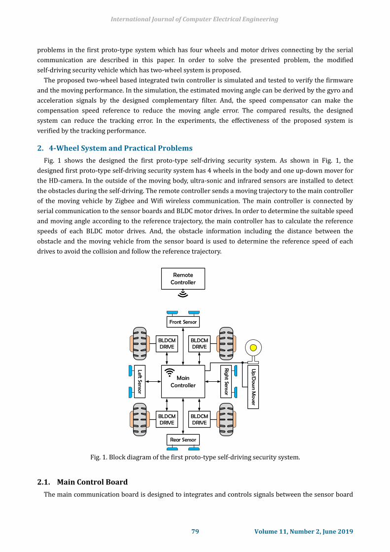
In the designed the first proto-type system, TMS320F28035 DSP(Digital Signal Processor) is used to drive
the BLDC In-wheel motor. Fig. 4 shows the designed BLDC motor drive. 20A grade IPM(Intelligent Power
Module) and chip type current sensor are used.
Fig. 4. The proto-type BLDC drive.
Camera and Up/Down Mover 2.4.
The up and down mover is used to operate the HD-camera. The total moving distance is 400mm. The DC
motor with hall sensor is adopted to operate the up and down mover of the HD-camera.
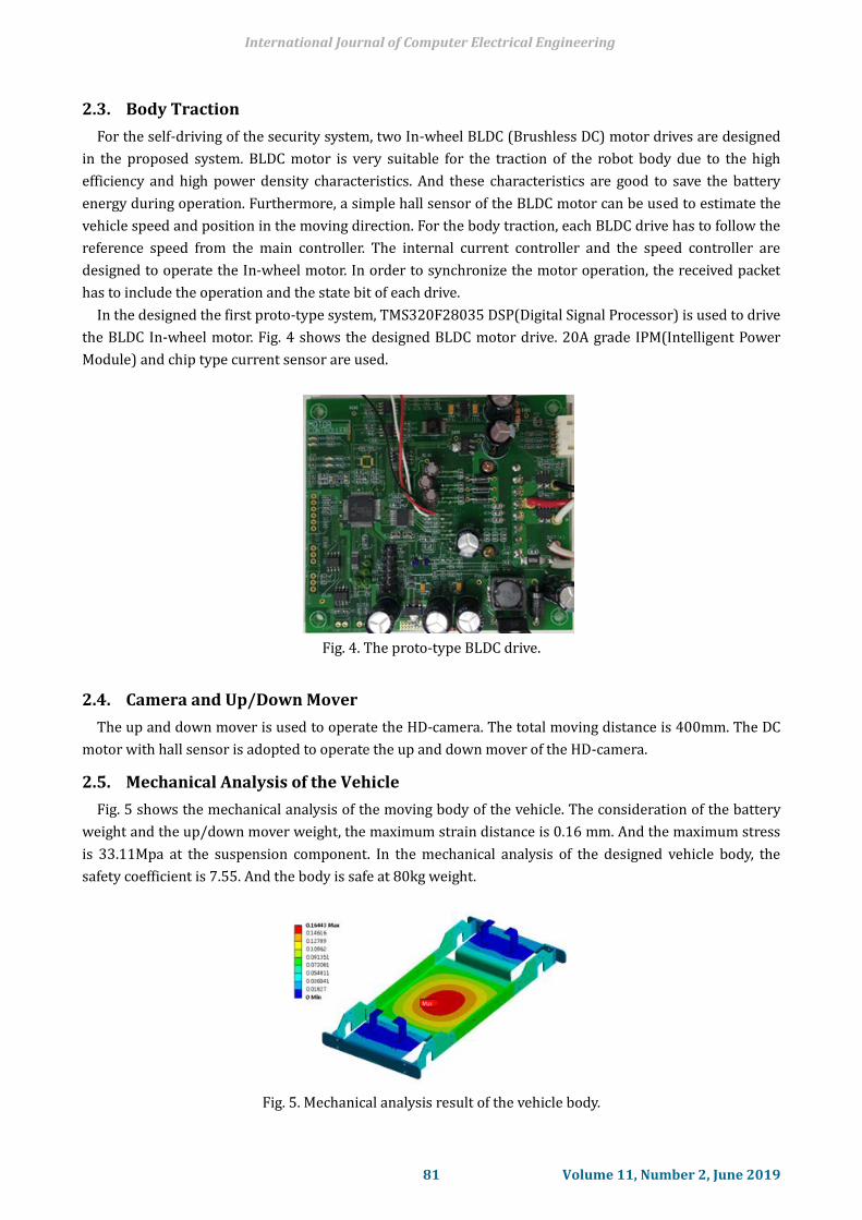
Mechanical Analysis of the Vehicle 2.5.
Fig. 5 shows the mechanical analysis of the moving body of the vehicle. The consideration of the battery
weight and the up/down mover weight, the maximum strain distance is 0.16 mm. And the maximum stress
is 33.11Mpa at the suspension component. In the mechanical analysis of the designed vehicle body, the
safety coefficient is 7.55. And the body is safe at 80kg weight.
Fig. 5. Mechanical analysis result of the vehicle body.
International Journal of Computer Electrical Engineering
81 Volume 11, Number 2, June 2019
Firmware Design and Practical Problems 2.6.
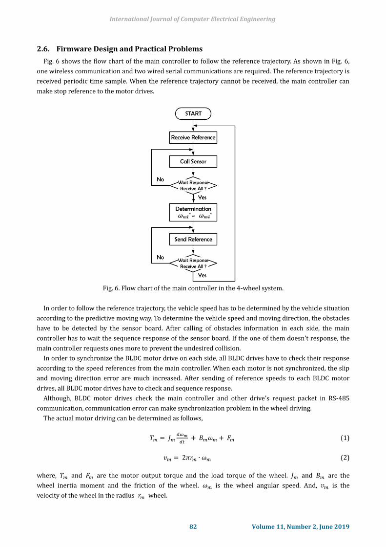
Fig. 6 shows the flow chart of the main controller to follow the reference trajectory. As shown in Fig. 6,
one wireless communication and two wired serial communications are required. The reference trajectory is
received periodic time sample. When the reference trajectory cannot be received, the main controller can
make stop reference to the motor drives.
START
Call Sensor
Receive Reference
Wait ResponseReceive All ?
Determination~
Yes
No
ωm1* ωm4*
Send Reference
Wait ResponseReceive All ?
Yes
No
Fig. 6. Flow chart of the main controller in the 4-wheel system.
In order to follow the reference trajectory, the vehicle speed has to be determined by the vehicle situation
according to the predictive moving way. To determine the vehicle speed and moving direction, the obstacles
have to be detected by the sensor board. After calling of obstacles information in each side, the main
controller has to wait the sequence response of the sensor board. If the one of them doesn’t response, the
main controller requests ones more to prevent the undesired collision.
In order to synchronize the BLDC motor drive on each side, all BLDC drives have to check their response
according to the speed references from the main controller. When each motor is not synchronized, the slip
and moving direction error are much increased. After sending of reference speeds to each BLDC motor
drives, all BLDC motor drives have to check and sequence response.
Although, BLDC motor drives check the main controller and other drive’s request packet in RS-485
communication, communication error can make synchronization problem in the wheel driving.
The actual motor driving can be determined as follows,
𝑇𝑚 = 𝐽𝑚𝑑𝜔𝑚
𝑑𝑡 + 𝐵𝑚𝜔𝑚 + 𝐹𝑚 (1)
𝑣𝑚 = 2𝜋𝑟𝑚 ∙ 𝜔𝑚 (2)
where, 𝑇𝑚 and 𝐹𝑚 are the motor output torque and the load torque of the wheel. 𝐽𝑚 and 𝐵𝑚 are the
wheel inertia moment and the friction of the wheel. 𝜔𝑚 is the wheel angular speed. And, 𝑣𝑚 is the
velocity of the wheel in the radius 𝑟𝑚 wheel.
International Journal of Computer Electrical Engineering
82 Volume 11, Number 2, June 2019

ωm1 ωm2
Fm1 Fm2
Tm1 Tm2rm2rm1
Fig. 7. Slip effect of the vehicle.
Fig. 7 shows the synchronization and the slip effect of the vehicle in the 4 wheel system. In Fig. 7, the one
side wheels are presented in the same reference speed. When the reference speed is same as to the two
wheels, the actual speed cannot be same due to the wheel size, torque error of the drive, friction and load
condition of each wheel. The wheel is strong connected to the vehicle body. The speed error between the
two wheels on the same side makes additional load disturbance.
In Fig. 7, the speed error and the non-linear disturbance can be described as follow,
∆𝑣𝑚 = 𝑣𝑚1 − 𝑣𝑚2 = 2𝜋(𝑟𝑚1𝜔𝑚1 − 𝑟𝑚2𝜔𝑚2) (3)
∆𝐹𝑚 = 𝑚 ∙∆𝑣𝑚
𝑑𝑡 (4)
Because of the speed error between the two wheels on the same side, the actual moving of the vehicle is
not smooth with trajectory error.
In order to improve the moving characteristic of the vehicle and the synchronization problem between
BLDC motor drives, the two wheel system with twin controller is proposed in this paper. The proposed
2-wheel system uses one wheel in left and right side to run the vehicle. And, non-electrical four additional
cast wheels are installed in the front and rear side to balance the vehicle [14]-[17].
3. Design of the 2-Wheel Model
Twin Motor Control System 3.1.
Fig. 8 shows the designed proto-type Twin BLDC drive board. In conventional BLDC board,
communication problems occur because each BLDC drive board is separated. Also, it is difficult to accurate
control the BLDC motor due to the use of different DSP. It is possible to improve the accuracy of the motor
control by improving the problem caused by the communication occurring in the existing board and
transmitting the driving signal from one DSP.
In the designed the twin control system TMS320F2811 DSP is used to drive the BLDC In-wheel motor
Fig. 8. The proto-type twin BLDC drive board.
International Journal of Computer Electrical Engineering
83 Volume 11, Number 2, June 2019

Fig. 9 shows the basic configurations of the proposed 2-wheel system and it’s mechanical structure. As
shown in Fig. 7, the 2nd designed system has two electric wheels and additional four non-electric wheels.
The two electric wheels are controlled by the one processor on the main controller to solve the
synchronization problem in the serial communication. And, the DC motor of the up/down mover is
controlled in the main controller. For this integration, the processor of the main controller has to have 14
PWM channels and 2 channels of UART with high resolution ADC (Analog to Digital Conversion) for the
BLDC motor control. Furthermore, enough QEP (Quadrature Encoder Pulse) function module is required to
capture the hall sensor signal of the motors. For the design of the proposed 2-wheel system, TMS320F2811
by TI(Texas Instruments) is used for the main controller. TMS320F2811 has 16 channels of PWM, 16
channels of 12-bit ADC, 2 channels of UART and 2 channels of QEP modules.
BLDCMDRIVE
DC Motor DRIVE
Front Sensor
Rear Sensor
Left Sensor
Right Sensor
Up
/Dow
n Mover
MainTWIN Controller
(a) Block diagram of the 2-wheel system. (b) Mechanical structure of the 2-wheel system.
Fig. 9. The configurations of the proposed 2-wheel system.
Moving Angle Error Compensation 3.2.
In the proposed design, the actual moving of the designed vehicle has the practical problem due to the
wheel size error, torque error, speed error and the slip between the wheel and road surface.
Fig. 10 shows the practical moving error in the 2-wheel vehicle system.
x
y
xref
yref
vW1 vW2
ωW1 ωW2
θm
vm
θm*
ym
xm
rm
Fig. 10. The actual moving of two wheels vehicle system.
In the Fig. 10, the actual position and the dynamic characteristic of the vehicle can be derived as follows,
International Journal of Computer Electrical Engineering
84 Volume 11, Number 2, June 2019

[ 𝑑𝑥𝑚(𝑡)
𝑑𝑡𝑑𝑦𝑚(𝑡)
𝑑𝑡𝑑𝜃𝑚(𝑡)
𝑑𝑡 ]
= [
𝑣𝑚(𝑡) ∙ cos(𝜃𝑚(𝑡))
𝑣𝑚(𝑡) ∙ sin(𝜃𝑚(𝑡))
𝜔𝑚(𝑡)
] (5)
[ 𝑑2𝑥𝑚(𝑡)
𝑑𝑡
𝑑2𝑦𝑚(𝑡)
𝑑𝑡
𝑑2𝜃𝑚(𝑡)
𝑑𝑡 ]
=
[ −𝑣𝑚(𝑡) ∙ sin(𝜃𝑚(𝑡)) ∙
𝑑𝜃𝑚(𝑡)
𝑑𝑡+
𝑑𝑣𝑚(𝑡)
𝑑𝑡∙ cos(𝜃𝑚(𝑡))
𝑣𝑚(𝑡) ∙ cos(𝜃𝑚(𝑡)) ∙𝑑𝜃𝑚(𝑡)
𝑑𝑡+
𝑑𝑣𝑚(𝑡)
𝑑𝑡∙ sin(𝜃𝑚(𝑡))
𝑑𝜔𝑚(𝑡)
𝑑𝑡 ]
(6)
And, the moving angle error can be expressed by the speed error of two wheels.
𝜃𝑚∗ (𝑘) − 𝜃𝑚(𝑘) = ∫(𝜔𝑚
∗ − 𝜔𝑚) ∙ 𝑑𝑡 (7)
In the practical system, the actual position of the vehicle cannot be measured. Only motor speed and
position can be controlled by the designed twin controller. In order to compensate the moving trajectory
angle error, the gyro sensor based compensation is proposed.
In the standstill position, the system angular position can be estimated by the gyro and acceleration
information using the complementary filter as follows,
�̇�𝑔(𝑘) = [
�̇�(𝑘)
�̇�(𝑘)
�̇�(𝑘)
] = [
1 𝑠𝑖𝑛𝜙(𝑘 − 1)𝑡𝑎𝑛𝜃(𝑘 − 1) 𝑐𝑜𝑠𝜙(𝑘 − 1)𝑡𝑎𝑛𝜃(𝑘 − 1)0 𝑐𝑜𝑠𝜙(𝑘 − 1) − 𝑠𝑖𝑛𝜙(𝑘 − 1)
0 𝑠𝑖𝑛𝜙(𝑘−1)
𝑐𝑜𝑠𝜃(𝑘−1)
𝑐𝑜𝑠𝜙(𝑘−1)
𝑐𝑜𝑠𝜃(𝑘−1)
] ⌊
𝜔𝑥(𝑘)𝜔𝑌(𝑘)𝜔𝑍(𝑘)
⌋ (8)
𝜃𝑎 (𝑘) = [�̇�(𝑘)
�̇�(𝑘)] = ⌊
sin−1 [ −𝐴𝑦(𝑘)
𝑔𝑐𝑜𝑠𝜃(𝑘−1) ]
sin−1 [ 𝐴𝑥(𝑘)
𝑔 ]
⌋ (9)
And we can estimate the system position by the complementary filter shown in Fig. 11.
Gyro
sensor
HPF
θg(k).
Ki+
-θm(k+ 1)
+-
s
1
s
1
Kp
++
LPF
Acc.
sensor
θa(k)
Fig. 11. The complementary filter of the two-wheel system.
From the estimated position of the system, the moving angle compensator can be designed by the
separated speed balance controller shown in Fig. 12.
+
-θm(k)
* Kips
1
Kpp
+ ωc(k+ 1)*
2
1 ++
ω1(k)*
-
ω2(k)*
ωW1(k)*
ωW2(k)*
θm(k)
Compensator
+
-
+-
+
Fig. 12. The proposed moving angle compensator.
International Journal of Computer Electrical Engineering
85 Volume 11, Number 2, June 2019
The compensation reference 𝜔𝑐∗(𝑘) is divided by two components. One reference is added and, other
reference is subtracted to adjust the moving system direction.
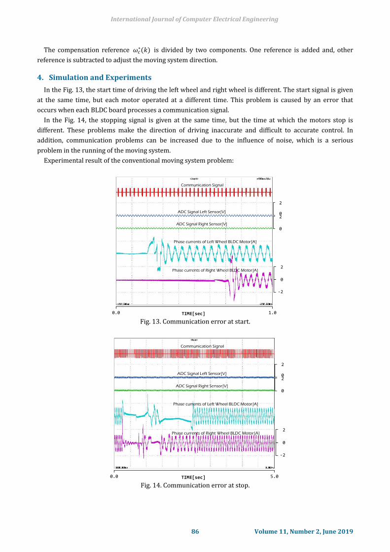
4. Simulation and Experiments
In the Fig. 13, the start time of driving the left wheel and right wheel is different. The start signal is given
at the same time, but each motor operated at a different time. This problem is caused by an error that
occurs when each BLDC board processes a communication signal.
In the Fig. 14, the stopping signal is given at the same time, but the time at which the motors stop is
different. These problems make the direction of driving inaccurate and difficult to accurate control. In
addition, communication problems can be increased due to the influence of noise, which is a serious
problem in the running of the moving system.
Experimental result of the conventional moving system problem:
Phase currents of Left Wheel BLDC Motor[A]
Phase currents of Right Wheel BLDC Motor[A]
0.0 TIME[sec] 1.0
2
-2
0
0
2
ADC Signal Left Sensor[V]
ADC Signal Right Sensor[V]
Communication Signal
0
2
Fig. 13. Communication error at start.
Phase currents of Left Wheel BLDC Motor[A]
Phase currents of Right Wheel BLDC Motor[A]
0.0 TIME[sec] 5.0
2
-2
0
0
2
ADC Signal Left Sensor[V]
ADC Signal Right Sensor[V]
Communication Signal
0
2
Fig. 14. Communication error at stop.
International Journal of Computer Electrical Engineering
86 Volume 11, Number 2, June 2019

θm*θm
Phase currents of Left Wheel BLDC Motor
Phase currents of Right Wheel BLDC Motor
vW1vW2
Fig. 15. Simulation result of the moving system in the proposed method.
Fig. 15 shows the MATLAB simulation result of the moving system in the proposed control method. As
shown in Fig. 15, it can be seen that the angle error between the two wheels during driving is reduced by
the proposed angle compensation method. Experimental result of the moving system:
Phase currents of Right Wheel BLDC Motor[A]
Phase currents of Left Wheel BLDC Motor[A]
0.0 TIME[sec] 5.0
2
-2
0
0
2
ADC Signal Left Sensor[V]
ADC Signal Right Sensor[V]0
2
2
-2
0
Fig. 16. Left distance sensor activated.
International Journal of Computer Electrical Engineering
87 Volume 11, Number 2, June 2019

Fig. 16 shows the experimental results for the detection of obstacles during operation. In Fig. 16, the
obstacle is detected from the left side. When the distance from the obstacle is close to a certain distance, the
speed of the right wheel decreases and the moving system moves to the right.
Phase currents of Right Wheel BLDC Motor[A]
Phase currents of Left Wheel BLDC Motor[A]
0.0 TIME[sec] 5.0
2
-2
0
0
2
ADC Signal Left Sensor[V]
ADC Signal Right Sensor[V]0
2
2
-2
0
Fig. 17. Right distance sensor activated.
Fig. 17 shows the experimental results when the obstacle is detected from the right side. In contrast to
Fig. 16, the driving system moves to the left as the speed of the left wheel decreases.
Phase currents of Left Wheel BLDC Motor[A]
Phase currents of Right Wheel BLDC Motor[A]
0.0 TIME[sec] 1.0
2
-2
0
0
2
ADC Signal Left Sensor[V]
ADC Signal Right Sensor[V]
Communication Signal
0
2
Fig. 18. Experimental result of the moving system in the proposed method.
Fig. 18 shows the experimental results of the proposed Twin Motor Control system. As shown in the Fig.
18, each motor can be operated simultaneously according to the start signal. Therefore, in the proposed
system, the start and stop error due to the communication error does not occur and the moving angle error
decreases.
5. Conclusion
In this paper, the design and modeling of a wirelessly controlled self-driving security system with
International Journal of Computer Electrical Engineering
88 Volume 11, Number 2, June 2019
in-wheel motor drivers were proposed. A conventional four-wheel BLDC drive system has some problems in
changing direction during rotation, simultaneous operation of multiple BLDC motor controllers, and torque
errors.
Therefore, a two-wheel system was adopted instead and a twin board configuration controlled by a single
DSP was designed. During operation, the actual speed cannot match with the reference value because of the
wheel size, torque error, and friction between wheel and surface. To compensate for the error, a control
algorithm and complementary filter with gyro and acceleration sensor were designed. Through both
simulation and experiment, it can be seen that the communication and angular errors were significantly
reduced
Acknowledgment
This research was supported by The Leading Human Resource Training Program of Regional Neo
industry through the National Research Foundation of Korea (NRF) funded by the Ministry of Science, ICT
and future Planning (NRF-2016H1D5A1910536).
References
[1] Naranjo, J. E., Gonzalez, G., Garcia, R., Pedro, T., & Haber, R. E. (2005). Power-steering control
architecture for automatic driving. IEEE Transactions on Intelligent Transportation Systems, 6(4),
406-415
[2] Kwon, H. K., & Chung, W. J. (2012). Comparisonal analysis of path planning methods for automatic
parking control of a car-like mobile robot. JICRS, 18(3), 267-274.
[3] Micheloni, C., Foresti, G. L., Piciarelli, C., & Cinque, L. (2007). An autonomous vehicle for video
surveillance of indoor environments. IEEE Transactions on Vehicular Technology, 56(2), 487-498.
[4] Park, H. G., Lee, H. G., & Kwon, S. H. (2012). Design of autonomous navigation systems based on
wireless networks. Korean Institute of Intelligent Systems, 22(4), 435-440.
[5] Potluri, R., & Singh, A. K. (2015). Path-tracking control of an autonomous 4WS4WD electric vehicle
using its natural feedback loops. IEEE Transactions on Control Systems Technology, 23(5), 2053-2062.
[6] Boyuan, L., Haiping, D., & Weihua, L. (2016). Trajectory control for autonomous electric vehicles with
in-wheel motors based on a dynamics model approach. IET Intelligent Transport Systems, 10(5), 318.
[7] Song, G., Wang, H., Zhang, J., & Meng, T. (2011). Automatic docking system for recharging home
surveillance robots. IEEE Transactions on Consumer Electronics, 57(2), 428-435.
[8] Bae, J. N., & Lee, D. H. (2018). Position control of a rail guided mover using a low-cost BLDC motor. IEEE
IA, 54, 2392-2399.
[9] Yoon, M., & Chang, J.-W. (2012). Design and implementation of an advanced cattle shed management
system using an infrared wireless sensor nodes and surveillance camera. J. Korea Contents Assoc.,
12(10), 22–34.
[10] Song. G., Yin, K., Zhou, Y., & Cheng, X. (2009). A surveillance robot with hopping capabilities for home
security. IEEE Transactions on Consumer Electronics, 55(4), 2034-2039.
[11] Parada-Salado, J. G., Ortega-Garcia, L. E., Ayala-Ramirez, L. F., Perez-Pinal, F. J., Herrera-Ramirez, C. A., &
Padilla-Medina, A. (2018). A low-cost land wheeled autonomous mini-robot for in-door surveillance.
IEEE Latin America Transactions, 16(5), 1298-1305.
[12] Vieira, A. W., Drews, P. L. J., & Campos, M. F. M. (2014). Spatial density patterns for efficient change
detection in 3D environment for autonomous surveillance robots. IEEE Transactions on Automation
Science and Engineering, 11(3), 766-774.
[13] Zhang, J., Song, G., Qiao, G., Meng, T., & Sun, H. (2011). An indoor security system with a jumping robot
International Journal of Computer Electrical Engineering
89 Volume 11, Number 2, June 2019

as the surveillance terminal. IEEE Transactions on Consumer Electronics, 57(4), 1774-1781.
[14] Lee, H. J., & Jung, S. (2011). Balancing control of a two wheeled mobile robot system. IEIE, 48(6), 1-7.
[15] Xu, J. X., Guo, Z. Q., & Lee, T. H. (2014). Design and implementation of integral sliding-mode control on
an underactuated two-wheeled mobile robot. IEEE Transactions on Industrial Electronics, 61(7),
3671-3681
[16] Sun, D., Feng, G., Lam, C. M., & Dong, H. (2005). Orientation control of a differential mobile robot
through wheel synchronization. IEEE/ASME Transactions on Mechatronics, 10(3), 345-351.
[17] Liu, C., Wang, M., & Zhou, J. (2008). Coordinating control for an agricultural vehicle with individual
wheel speeds and steering angles. IEEE Control Systems, 28(5), 21-24.
Jongnam Bae was born on June 20, 1991. He received the B.S. and M.S. degrees in
mechatronics engineering from Kyungsung University, Busan, South Korea, in 2016 and
2018, respectively, where he is currently working toward the Ph.D. degree with the
Department of Mechatronics Engineering. His research interest includes control of
blushless dc motors.
Seungjun Kim was born on April 25, 1991. He received the B.S. degrees in mechatronics
engineering form Kyungsung University, Busan, South Korea, in 2017, respectively, where
he is currently working toward the M.S. degree with the Department of Mechatronics
Engineering. His research interest includes control of blushless dc motors.
Dong-Hee Lee was born on November 11, 1970. He received the B.S., M.S., and Ph.D.
degrees in electrical engineering from Pusan National University, Busan, South Korea, in
1996, 1998, and 2001, respectively. From 2002 to 2005, he was a senior researcher in the
Servo Research and Development Team, OTISLG Company, South Korea. Since 2005, he has
been a professor with the Department of Mechatronics Engineering, Kyungsung University.
In 2012, he was a visiting professor at the University of Wisconsin–Madison, Madison, WI,
USA. His research interests include power electronics and motor control systems. Dr. Lee is an associate
editor for the Journal of Power Electronics.
International Journal of Computer Electrical Engineering
90 Volume 11, Number 2, June 2019