Modeling and Control of 5DOF Robot Arm Using Fuzzy Logic Supervisory Control
13
International Journal of Robotics and Automation (IJRA) Vol. 2, No. 2, June 2013, pp. 56~68 ISSN: 2089-4856 56 Journal homepage: http://iaesjournal.com/online/index.php/IJRA Modeling and Control of 5DOF Robot Arm Using Fuzzy Logic Supervisory Control Mohammad Amin Rashidifar 1 , Ali Amin Rashidifar 2 , Darvish Ahmadi 1 1 Department of Mechanical Engineering, Islamic Azad University, Shadegan Branch, Shadegan, Iran 2 Department of Computer Science, Islamic Azad University, Shadegan Branch, Shadegan, Iran Article Info ABSTRACT Article history: Received Jan 22, 2013 Revised Apr 20, 2013 Accepted May 6, 2013 Modeling and control of 5 degree of freedom (DOF) robot arm is the subject of this article. The modeling problem is necessary before applying control techniques to guarantee the execution of any task according to a desired input with minimum error. Deriving both forward and inverse kinematics is an important step in robot modeling based on the Denavit Hartenberg (DH) representation. Proportional integral derivative (PID) controller is used as a reference benchmark to compare its results with fuzzy logic controller (FLC) and fuzzy supervisory controller (FSC) results. FLC is applied as a second controller because of the nonlinearity in the robot manipulators. We compare the result of the PID controller and FLC results in terms of time response specifications. FSC is a hybrid between the previous two controllers. The FSC is used for tuning PID gains since PID alone performs not satisfactory in nonlinear systems. Hence, comparison of tuning of PID parameters is utilized using classical method and FSC method. Based on simulation results, FLC gives better results than classical PID controller in terms of time response and FSC is better than classical methods such as Ziegler-Nichols (ZN) in tuning PID parameters in terms of time response. Keyword: Fuzzy logic controller Kinematic analysis Linearcontrol Nonlinearcontrol Copyright © 2013 Institute of Advanced Engineering and Science. All rights reserved. Corresponding Author: Mohammad Amin Rashidifar Departement of Mechanical Engineering, Islamic Azad University, Shadegan Branch. Email: [email protected] 1. INTRODUCTION In recent years, industrial and commercial systems with high efficiency and great performance have taken advantages of robot technology. Large number of control researches and numerous control applications were presented during the last years, concentrated on control of robotic systems. Robot manipulator field is one of the interested fields in industrial, educational and medical applications. It works in unpredictable, hazard and inhospitable circumstances which human cannot reach [1-2]. For example, working in chemical or nuclear reactors is very dangerous, while when a robot instead human it involves no risk to human life. Therefore, modeling and analysis of the robot manipulators and applying control techniques are very important before using them in these circumstances to work with high accuracy. This article is meant to be suitable for these applications. On the other side, some universities and colleges offers, some courses related to robotics. These courses mainly focus on the theoretical concepts without giving much attention for controlling different robot manipulators in the practical side. This article may be considered as a valuable educational tool in their laboratories. The essential problem is to study the robot manipulator problem from two sides: the first one is the mathematical modeling of the manipulator and the actuators, which includes an analysis for the forward kinematic, the inverse kinematic and modeling the direct current (DC) motor because it is an important issue in a robot manipulator. The second problem is the control of the robot manipulator. The main objective of this article is concerned with designing a controller for the motion of the robot manipulator to meet the requirement of the desired trajectory input with suitable error and disturbance values.
-
Upload
cuecamilectic -
Category
Documents
-
view
23 -
download
0
Transcript of Modeling and Control of 5DOF Robot Arm Using Fuzzy Logic Supervisory Control
International Journal of Robotics and Automation (IJRA) Vol. 2, No. 2, June 2013, pp. 56~68 ISSN: 2089-4856 56
Journal homepage: http://iaesjournal.com/online/index.php/IJRA
Modeling and Control of 5DOF Robot Arm Using Fuzzy Logic Supervisory Control
Mohammad Amin Rashidifar1, Ali Amin Rashidifar2, Darvish Ahmadi1
1Department of Mechanical Engineering, Islamic Azad University, Shadegan Branch, Shadegan, Iran 2Department of Computer Science, Islamic Azad University, Shadegan Branch, Shadegan, Iran
Article Info ABSTRACT
Article history:
Received Jan 22, 2013 Revised Apr 20, 2013 Accepted May 6, 2013
Modeling and control of 5 degree of freedom (DOF) robot arm is the subject of this article. The modeling problem is necessary before applying control techniques to guarantee the execution of any task according to a desired input with minimum error. Deriving both forward and inverse kinematics is an important step in robot modeling based on the Denavit Hartenberg (DH) representation. Proportional integral derivative (PID) controller is used as a reference benchmark to compare its results with fuzzy logic controller (FLC) and fuzzy supervisory controller (FSC) results. FLC is applied as a second controller because of the nonlinearity in the robot manipulators. We compare the result of the PID controller and FLC results in terms of time response specifications. FSC is a hybrid between the previous two controllers. The FSC is used for tuning PID gains since PID alone performs not satisfactory in nonlinear systems. Hence, comparison of tuning of PID parameters is utilized using classical method and FSC method. Based on simulation results, FLC gives better results than classical PID controller in terms of time response and FSC is better than classical methods such as Ziegler-Nichols (ZN) in tuning PID parameters in terms of time response.
Keyword:
Fuzzy logic controller Kinematic analysis Linearcontrol Nonlinearcontrol
Copyright © 2013 Institute of Advanced Engineering and Science. All rights reserved.
Corresponding Author:
Mohammad Amin Rashidifar Departement of Mechanical Engineering, Islamic Azad University, Shadegan Branch. Email: [email protected]
1. INTRODUCTION
In recent years, industrial and commercial systems with high efficiency and great performance have taken advantages of robot technology. Large number of control researches and numerous control applications were presented during the last years, concentrated on control of robotic systems. Robot manipulator field is one of the interested fields in industrial, educational and medical applications. It works in unpredictable, hazard and inhospitable circumstances which human cannot reach [1-2]. For example, working in chemical or nuclear reactors is very dangerous, while when a robot instead human it involves no risk to human life. Therefore, modeling and analysis of the robot manipulators and applying control techniques are very important before using them in these circumstances to work with high accuracy. This article is meant to be suitable for these applications. On the other side, some universities and colleges offers, some courses related to robotics. These courses mainly focus on the theoretical concepts without giving much attention for controlling different robot manipulators in the practical side. This article may be considered as a valuable educational tool in their laboratories. The essential problem is to study the robot manipulator problem from two sides: the first one is the mathematical modeling of the manipulator and the actuators, which includes an analysis for the forward kinematic, the inverse kinematic and modeling the direct current (DC) motor because it is an important issue in a robot manipulator. The second problem is the control of the robot manipulator. The main objective of this article is concerned with designing a controller for the motion of the robot manipulator to meet the requirement of the desired trajectory input with suitable error and disturbance values.
IJRA ISSN: 2089-4856
Modeling and Control of 5DOF Robot Arm Using Fuzzy Logic Supervisory… (Mohammad Amin Rashidifar)
57
The motivation of control technique designs the usage of the high precision performance of the robot manipulators in complicated and hazardous environments. Various controllers have been designed and applied in the robot manipulator. The first question that may arise is the different types of these controllers and the difference between these controllers in terms of best performance will be shown. Proportional Integral Derivative (PID) controller may be the most widely used controller in the industrial and commercial applications for the early decades, due to its simplicity of designing and implementation, so the first attempt is to apply PID control; however, PID does not give optimal performance due to the nonlinear elements. Robot manipulators are classified as nonlinear systems, so classical controllers are not sufficient to give the best results. Fuzzy logic controller (FLC) was found to be an efficient tool to control nonlinear systems. Designing and testing FLC will be shown as a second option. In recent years, hybrid between fuzzy and classical controllers has combined to design a controller such as fuzzy plus PID and fuzzy logic supervisory (FLS) creates more appropriate solution to control robot manipulator. Through the article, FLC is considered as an important controller for on-line tuning of PID parameters. FLC may design to monitor and enhance the PID parameters online. The robot movements' analysis is important before the implementation of the actual system in order to prevent possible environmental hazards. Therefore, computer simulations are important to perform any controller, where developing distinct mathematical model for any robot manipulator is an important issue to perform the simulations.
2. LINEAR AND NONLINEAR CONTROL There are two methods used in control theory to control systems, linear method and nonlinear
method. Using linear control is applicable only when the controlled system can be modeled mathematically [3]. The facts that the majority of physical systems have nonlinear characteristics; hence, linear controllers fail to meet the requirements due to system nonlinearities. The variations and the nonlinear parameters such as gear backlash, load variations and other parameters have unpredictable effects on the controlled systems (e.g. robot manipulator) diminish the performance. Therefore, the robot manipulator may be considered as a linear model when it works on small space, or it has a large gear ratio between the joints and their links. Nonlinear methods considered as general case when compared to linear methods because it can be applied successfully on the linear methods, but linear method is not sufficient to solve and control nonlinear problems. Common methodologies are used to solve the nonlinearities in control systems such as sliding mode control, and state feedback control are discussed in [4].
3. CONTROL TECHNIQUES Due to uncertainty and instability effects, unknown or unpredictable inputs that manipulate the plant
output to the incorrect target. These inputs are called disturbance or noise, so analyzing and designing the mathematical model of the system includes the controller and plants to get the desired behavior is required. Many control techniques have been proposed to control robot manipulator ranging in complexity from linear to the advanced control system, which compute the robot dynamic and save it from damage in real environments. Three different control schemes namely PID controller, FLC, and the fuzzy supervisory controller (FSC) will be implemented through this article. The performance of these controllers will be based on the high precision in reducing the overshoot, minimizing steady state error, damping unwanted vibration of robot manipulator, and handling the unpredictable disturbances. PID controller is one of the earliest controllers in the industrial robot manipulators, so the first attempt to control the plant is use the PID controller. PID controller is still considered the most widely used in industry [5] and [6]. The popularity of using the PID or the PID-types controllers is that they have a simple structure, and they give satisfactory results when the requirements are reasonable and the process parameters variations are limited. In addition, the majority of applications are familiar with the PID controller based on the knowledge of the system characteristics. Several techniques used for tuning PID parameters that have been developed over the past decade such as Ziegler-Nichols (Z-N) tuning methods [7]. One of the drawbacks for using the PID control techniques is that, they are not sufficient to obtain the desired tracking control performance because of the nonlinearity of the robot manipulator. Hence, a lot of time is required to tune the PID parameters. On the other hand, other techniques are used to overcome the previous problem, such as fuzzy controller that emulates human operation. FLC is an emerging technique in control systems. It is considered as intelligent controller. Many studies show that the fuzzy controller (FC) performs superior to conventional controller algorithms will be discussed in the next section. Zadeh [8] did the main idea of FLC and fuzzy set theory.
Mamdani and his colleagues [9] have done a pioneering research work on FLC in the mid-’70 for engine steam boiler. The benefit of FLC is obvious when the controlled process is too complicated to be analyzed using PID controller or when the information about the controlled system does not exist. FLC is

ISSN: 2089-4856
IJRA Vol. 2, No. 2, June 2013 : 56 – 68
58
classified into two categories: the first, involves the fuzzy logic system based on a rule based on expert system, to determine the control action. The second used FL to provide online adjustment for the parameters of the conventional controller such as the PID control [10]. This method attempts to combine the merits of FL with those control techniques to expand the capability of linear control technique to handle the nonlinearity in the physical system. Fuzzy supervisory is used to reduce the amount of tuning the PID controller with a fuzzy system [11]. It is considered as an attractive method to solve the nonlinear control problems, one of the advantages of fuzzy supervisory that the control parameters changed rapidly with respect to the variation of the system response. The fuzzy supervisor operates in a manner similar to that of the FLC and adds a higher level of control to the existing system. Fuzzy supervisory is hybrid between the PID controller and FLC that designed to overcome the problem of tuning PID in nonlinear systems using FLC as an adaptive controller [12]. The basic structure of FSC resembles the structure of PID controller, but the controlled parameter of PID controller depends on the output of the fuzzy controller.
4. KINEMATICS AND MATHEMATICAL MODELING There are two main classes in a robot manipulator: serial manipulators designed using an open loop
kinematic chain and parallel manipulator designed using closed loop kinematic chains. This article handles serial manipulators. Robot manipulator consists of a collection of n-links that
connected together by joints. Each one of these joints has a motor allowing the motion to the commanded link. The motors have feedback sensors to measure the output (e.g. position, velocity, and torque) at each instant. Links and joints form a kinematic chain connected to ground from one side, and the other is free. At the end of the open side, the end-effectors (e.g. gripper, welding tool, or another tool) are used to do some tasks as welding, or handle materials [2]. Robot manipulator is named according to number of DOF, which refers to the number of joints. As an example, robot manipulator has 5 joints, which mean the robot has 5DOF, and so on. In physical applications, it is important to describe the position of the end effectors of the robot manipulator in one global coordinates. In transforming, the coordinates of the end effectors from the local position to the global position, the robot movements are represented by a series of movements of rigid links. Each link defines a proper transformation matrix relating the position of the current link to the previous one. As mentioned previously, robot manipulator whose all joints are prismatic is known as a Cartesian manipulator while the robot whose joint variables are revolute is called an articulated manipulator. Figure 1 shows a Cartesian manipulator with 3 rigid bodies and three joint variables represents the Cartesian coordinates of the end effectorss with respect to the body 0, which is fixed.
Figure 1. Robot manipulator with PPP joints
Body 2 is fixed to body 1 and body 3 is fixed to body 2. The end effectors , body 3 and its movement relative to 2. The coordinate of the wrist point with respect to the fixed body is:
′ ′ (1)
Where, d1, d2, and d3 are the given range of motion. Kinematics is the motion geometry of the robot
manipulator from the reference position to the desired position with no regard to forces or other factors that influence robot motion [3]. In other words, the kinematics deals with the movement of the robot manipulator with respect to fixed frame as a function of time. The fixed frame in robot represents the base and all other
Christian Gonzalez
Resaltado
Christian Gonzalez
Resaltado
Christian Gonzalez
Resaltado

IJRA ISSN: 2089-4856
Modeling and Control of 5DOF Robot Arm Using Fuzzy Logic Supervisory… (Mohammad Amin Rashidifar)
59
movements measured from the base as reference. It is one of the most fundamental disciplines in robots, providing tools for describing the structure and behavior of robot manipulator mechanisms, and it is important in practical applications such as trajectory planning and control purposes. Generally, to control any robot manipulator the core of the controller is a description of kinematic analysis, this is done by using a common method in industrial and academic research, namely Denavit-Hartenberg method [1], [2] and [3].
The distinct of this method gives a mathematical description for all serial manipulators depending on the robot geometry, and it defines the position and orientation of the current link with respect to previous one. In addition, it allows the desired frame to create a set of steps to bring the other links coordinate into corresponding with another one. For more information, readers may return to the previous references. The kinematic solution in this chapter will focus on two important problem arises in robot manipulator. Section (2.2) discusses methodologies to solve the forward and inverse kinematic respectively. The first problem is determining the forward kinematic (FK) where the robot manipulator end-effectors will be if all joints are known. This means what rigid motion each joint effect on its link to obtain the desired configuration. The configuration space of the end-effectors contains the transformation matrix T that relates the position and orientation of the end-effectors. The following equation explains the forward kinematic problem.
, , … , , , , (2)
Where θ , θ and θ are the input variables, x, y, z are the desired position and R the desired
rotation. The second problem is determining the inverse kinematic (IK), which calculates the value of each joint variable if the desired position and orientation of end-effectors are known. That means if the final link configuration is known, what is the possible configuration (e.g. solutions) of the robot manipulator to move the end-effectors of the robot arm to desired position and orientation in space. Inverse kinematic problem may express mathematically as follows:
, , , , , … , (3)
For serial manipulators with revolute or prismatic joints the FK is derived using procedures such as
the DH convention matrix [3], but in the parallel manipulator, the forward kinematic be not easy to be solved due to the complexity of the robot manipulator.
Therefore, it may solved by using a set of nonlinear equations. On the other hand, solving the IK for parallel manipulator is easier than FK solution, and there are many solutions to achieve the desired task. The second issue that will be discussed is the DC motor modeling. DC motor modeling is an important issue before designing a controller to know the system characteristics and its mathematical model.
5. DC MOTOR MODELING Generally, modeling refers to system description in mathematical terms, which characterizes the
input-output relationship. Direct current (DC) motor is a common actuator found in many mechanical systems and industrial applications such as industrial and educational robots [3]. DC motor converts the electrical energy to mechanical energy. The motor directly has a rotary motion, and when combined with mechanical part it can provide translation motion for the desired link. Equation (4) states the relation between the current and developed torque in:
(4)
Whereτ t , is the motor torque produced by the motor shaft, φ the magnetic flux, i t , the
armature current, and K , is a proportional constant. Equation (5) illustrates the relation between the produced EMF and the shaft velocity:
(5)
Where v , denotes the back EMF, and ω , is the shaft velocity of the motor.
DC motors are important in control systems, so it is necessary to establish and analyze the mathematical model of the DC motors. Figure 2 shows the schematic of the armature controlled DC motor with a fixed field circuit.
Christian Gonzalez
Resaltado
Christian Gonzalez
Resaltado
Christian Gonzalez
Resaltado
Christian Gonzalez
Resaltado
ISSN: 2089-4856
IJRA Vol. 2, No. 2, June 2013 : 56 – 68
60
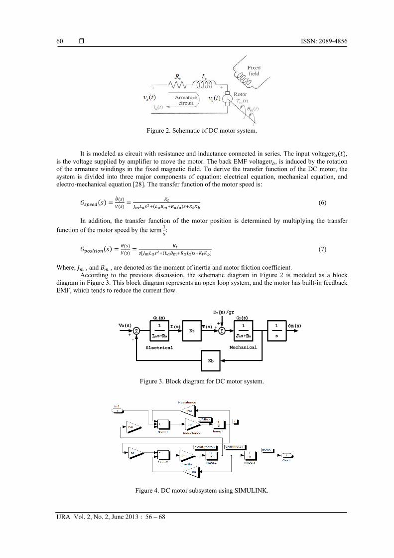
Figure 2. Schematic of DC motor system.
It is modeled as circuit with resistance and inductance connected in series. The input voltage , is the voltage supplied by amplifier to move the motor. The back EMF voltage , is induced by the rotation of the armature windings in the fixed magnetic field. To derive the transfer function of the DC motor, the system is divided into three major components of equation: electrical equation, mechanical equation, and electro-mechanical equation [28]. The transfer function of the motor speed is:
(6)
In addition, the transfer function of the motor position is determined by multiplying the transfer
function of the motor speed by the term :
(7)
Where, , and , are denoted as the moment of inertia and motor friction coefficient.
According to the previous discussion, the schematic diagram in Figure 2 is modeled as a block diagram in Figure 3. This block diagram represents an open loop system, and the motor has built-in feedback EMF, which tends to reduce the current flow.
Figure 3. Block diagram for DC motor system.
Figure 4. DC motor subsystem using SIMULINK.
IJRA ISSN: 2089-4856
Modeling and Control of 5DOF Robot Arm Using Fuzzy Logic Supervisory… (Mohammad Amin Rashidifar)
61
The advantage of using the block diagram gives a clear picture of the transfer function relation
between each block of the system. Therefore, based on the block diagram in Figure 3, the transfer function from to with 0 was illustrated in Equation (7). Transfer function from the load torque, to is given with 0.
⁄ (8)
Where, gr, is the gear ratio. Using SIMULINK, the model of the motor may be created. This model includes all the parameters derived previously. Figure 4 shows the SIMULINK model of DC motor.
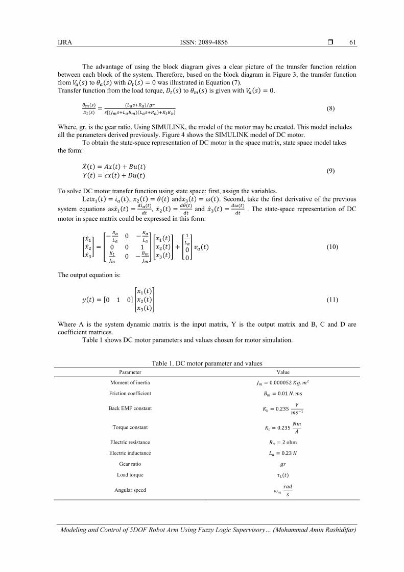
To obtain the state-space representation of DC motor in the space matrix, state space model takes the form:
(9)
To solve DC motor transfer function using state space: first, assign the variables.
Let , and . Second, take the first derivative of the previous
system equations as , and . The state-space representation of DC
motor in space matrix could be expressed in this form:
0
0 0 1
000
(10)
The output equation is:
0 1 0 (11)
Where A is the system dynamic matrix is the input matrix, Y is the output matrix and B, C and D are coefficient matrices.
Table 1 shows DC motor parameters and values chosen for motor simulation.
Table 1. DC motor parameter and values Parameter Value
Moment of inertia 0.000052 .
Friction coefficient 0.01 .
Back EMF constant 0.235
Torque constant 0.235
Electric resistance 2 ohm
Electric inductance 0.23
Gear ratio
Load torque
Angular speed

ISSN: 2089-4856
IJRA Vol. 2, No. 2, June 2013 : 56 – 68
62
To study the behavior of the DC motor, consider the system without disturbance, then; substitute the parameter values of DC motor from Table 1 into Equation (7). The open loop transfer function of the motor is:
(12)
Equation (12) can be written in the zero/pole/gain form as:
. . (13)
Response of Equation (13) is shown in Figure 5. As shown; the system does not go to steady state
value but to an increasing value. This means the armature rotates at a constant speed, which is achieved by its built-in velocity feedback factor.
Simulation results using SIMULINK are shown in Figure 5 and Figure 6 for DC motor model with and without load disturbance.
Figure 5. DC motor open loop step response without load
Figure 6. DC motor model simulation with load disturbance.

IJRA ISSN: 2089-4856
Modeling and Control of 5DOF Robot Arm Using Fuzzy Logic Supervisory… (Mohammad Amin Rashidifar)
63
Simulation results demonstrated that, the motor running at no-load conditions at startup, and still
running to reach the steady state value as shown in Figure 5. When a mechanical load is applied suddenly to the shaft as shown in Figure 6, a small no-load current did not produce enough torque to carry the load; thus, the motor starts to slow down. This cause counters EMF to diminish resulting in a higher current and a corresponding higher torque. When the torque developed by the motor is exactly equal to the torque imposed by the mechanical load, then the speed will remain constant.
6. FUZZY LOGIC CONTROLLER STRUCTURE Figure 7 shows the basic configuration of MISO fuzzy system, which comprises four main building
components: fuzzification method, rule base, inference mechanism, and defuzzification method. As seen in the figure, the input and output data of FLC are crisp (non-fuzzy) values. FLC components are:
1. The fuzzifier: measure the values of input variable and convert the input crisp values into suitable linguistic variables.
2. An expert and skilled operator define the knowledge base. The rule-base holds the knowledge, in the form of a set of rules, of how best to control the system.
3. The inference mechanism evaluates which control rules are relevant for the current time and then decides what the input to the plant should be.
4. The defuzzifier is the opposite operator of fuzzifier interface; it converts the conclusions reached by an inference mechanism into a real value as inputs to plant.
Figure 7. Fuzzy control system structure
Before illustrating FLC components, it is important to define the FLC inputs and output variables. The controller is used to correct the error signal then supply appropriate input to the plant. Two inputs are used for FLC: the error that generated from the feedback loop and derivative of the error, or it may also have an integral input for fuzzy like PI controller. In addition, when designing a fuzzy like PID controller the three inputs are used, and the output is a control signal feeds the plant.
The three variables e, ∆e and u of the FLC are the error, error change, and the output action, and the variables ̃ , ∆ ̃ , are their fuzzy counterparts respectively, y is the output, and r is the set point, is the scale factor of the error input, k is the scale factor of the error derivative, and the is the output gain.
Figure 8 shows the effect of fuzzy PD and fuzzy PI controller. Assume the reference input r = 60 implemented for the DC motor. The response shows that the fuzzy PD has a faster response 0.2 than fuzzy PI 0.3 . This means that the fuzzy PD controller rising time is less 33% than fuzzy PI rising time. However, the fuzzy PD controller has large steady sate error SSE 0.04 than the fuzzy PI controller where SSE 0.002.
Figure 8. Output of fuzzy PD and fuzzy PI for r = 60
ISSN: 2089-4856
IJRA Vol. 2, No. 2, June 2013 : 56 – 68
64
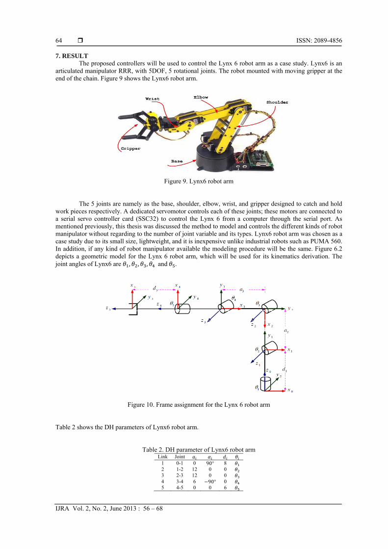
7. RESULT The proposed controllers will be used to control the Lynx 6 robot arm as a case study. Lynx6 is an
articulated manipulator RRR, with 5DOF, 5 rotational joints. The robot mounted with moving gripper at the end of the chain. Figure 9 shows the Lynx6 robot arm.
Figure 9. Lynx6 robot arm
The 5 joints are namely as the base, shoulder, elbow, wrist, and gripper designed to catch and hold work pieces respectively. A dedicated servomotor controls each of these joints; these motors are connected to a serial servo controller card (SSC32) to control the Lynx 6 from a computer through the serial port. As mentioned previously, this thesis was discussed the method to model and controls the different kinds of robot manipulator without regarding to the number of joint variable and its types. Lynx6 robot arm was chosen as a case study due to its small size, lightweight, and it is inexpensive unlike industrial robots such as PUMA 560. In addition, if any kind of robot manipulator available the modeling procedure will be the same. Figure 6.2 depicts a geometric model for the Lynx 6 robot arm, which will be used for its kinematics derivation. The joint angles of Lynx6 are , , , and .
Figure 10. Frame assignment for the Lynx 6 robot arm Table 2 shows the DH parameters of Lynx6 robot arm.
Table 2. DH parameter of Lynx6 robot arm Link Joint
1 0-1 0 90° 8 2 1-2 12 0 0 3 2-3 12 0 0 4 3-4 6 90° 0 5 4-5 0 0 6

IJRA ISSN: 2089-4856
Modeling and Control of 5DOF Robot Arm Using Fuzzy Logic Supervisory… (Mohammad Amin Rashidifar)
65
For testing the 5DOF Lynx6 robot arm, the joint desired input angles are θ
{120°, 66°, 100°, 45°, 15° with initial position of the robot arm is the home position θ 0°, 0°, 0°, 0°, 0° . Figure 11 shows the home position for the Lynx6 and Figure 12 shows the final configuration for the input joint variables.
In order to assess the efficacy of the proposed controller, simulation studies have been conducted to check the efficiency of the system. PID controller is tested as the first attempt to control the Lynx6 robot arm. Figure 13, Figure 14 and Figure 15 show the output response of the motors of the 5DOF Lynx6 using PID controllers.
Figure 11. Lynx6 home position Figure 12. Lynx6 desired position
Figure 13. PID control step response for ,
Figure 14. PID control step response for

ISSN: 2089-4856
IJRA Vol. 2, No. 2, June 2013 : 56 – 68
66
Figure 15. PID control step response for ,
Table 3 shows the performance of the PID controller.
Table 3. Performance of the PID controller Motor number Over shot (o.s) Rising time( ) Steady state error(s.s.e)
Motor 1 0.03 0.246 0.03 Motor 2 0.008 0.247 0.001 Motor 3 0.06 0.274 0.005 Motor 4 0.02 0.277 0.01 Motor 5 0.01 0.21 0.002
Figure 16. Output with disturbance for , .
Figure 17. Output with disturbance for θ

IJRA ISSN: 2089-4856
Modeling and Control of 5DOF Robot Arm Using Fuzzy Logic Supervisory… (Mohammad Amin Rashidifar)
67
Effect of disturbance is studied by performing simulation of the control system in the presence of
the disturbance. The disturbance is considered as the load torque that applied to the motor for each joint. The type of disturbance used in the simulation is step input disturbance. Figure 16 and Figure 17 shows the effect of disturbance on the output response of , and . In the presence of disturbance after one and a half second, the output of the angular position will deviate.
Simulations and numerical results, which compare between PID controller and fuzzy logic controller, prove that the performance of fuzzy logic controller is better than the PID performance for controlling robot manipulator in terms of reducing overshoot size, enhancing rising time and minimizing steady state error. As example, the steady state error of the motor one for the FLC is 0.006, while it is 0.03 for the PID controller. In other words, this means that the FLC steady state error is 80% less than the PID controller. The rising time for the FLC is 45% less than PID controller. Finally, the overshoot of FLC is 46% less than the PID controller.
The fuzzy supervisory PID controller is applied to 5DOF robot arm [65]. The robot has 5DOF each of them has a motor with specific transfer function. As a case study, we will present the output response of the fifth DOF of the robot arm, and we will show the variation of the PID gains through process control. The output response of the other motors can be obtained in the same way. The transfer function of the motor of the fifth DOF considered is:
.
. ∗ . . (14)
The results show the output response of the theta five of robot arm using the proposed controllers.
Simulation result in Figure 18 and Figure 19 show the output response of the proposed controllers using the step as input signal. The two figures below show the performance of the PID using the classical tuning (without fuzzy tuning) and using the supervisory tuning respectively. In addition, they show the effectiveness of the two controllers for rejection disturbance. If the load torque with -0.5 N.m is applied on the desired angle. The obtained result shows the effect of the disturbance on the output response after one second and the efficacy of the FSC controller for tuning PID parameters and eliminating the disturbance.
Figure 18. Output response using classical tuning methods
Figure 19. Output response using fuzzy supervisory control
Clearly, the supervisory fuzzy control achieved better performance than classical tuning methods in
terms of time response. The above figures show the effect of small disturbance after one second and effectiveness of the fuzzy supervisory control in eliminating the presence disturbances. Performance of the proposed controllers is summarized in Table 4.
Table 4. Output with and without fuzzy tuning Overshot (O.S) Rising time( ) Steady state error(s.s.e)
Tuning method 0.08 0.3 0.03 Classical tuning method
Tuning using FLC 0.001 0.15 0.001

ISSN: 2089-4856
IJRA Vol. 2, No. 2, June 2013 : 56 – 68
68
8. CONCLUSION Robotics has become recently an interesting area of research. In this thesis, we study the robot
manipulator from two sides: modeling and control. Modeling process includes kinematic analysis and DC motor modeling. This process is important before controlling the robot to save the robot from being damaged. Appling a control technique is important to guarantee high efficiency and lower error for the motion of the robot. The desired tasks were accomplished using three stages: the first stage was to provide systematic rules for analyzing forward and inverse kinematics solutions for the robot manipulator with revolute or prismatic joints using DH parameters, then analyzing the mathematical model of the DC motor in both frequency and time domains. In the second stage, we discussed the problem of control techniques. PID controller was applied, to control the robot manipulator, then FLC was implemented and considered as a second choice to control the robot. The third controller was a hybrid one between the previous controllers, denoted as FSC. In the third stage, we compared the results of using the three controllers for controlling the robot manipulator. First, we compared the results of the PID and the FLC techniques in terms of overshoot, transient response and steady state error. Second, we compared the results of PID classical tuning methods and fuzzy supervisory tuning method. All simulations were presented using MATLAB and SIMULINK, which are used widely in control applications. The objective of this article was to control Lynx6 robot arm to reach the specified location with minimum error while meeting certain specification. The tracking path from the initial position to the final position was not considered in this thesis; we Set the final position for each motor used independent joint control method. This article used the PID controller to compare its results with FLC and FSC. REFERENCES [1] MW Spong, S Hutchinson, M Vidyasagar. Robot Modeling and Control, 1st Edition, Jon Wiley & Sons, Inc. 2005. [2] J Angeles. Fundamentals of Robotic Mechanical Systems: Theory, Methods, and Algorithms, 2nd Edition, Springer.
2003. [3] JJ Crage. Introduction to Robotics Mechanics and Control, 3rd Edition, Prentice Hall. 2005. [4] KH Kalil. Nonlinear Systems, 3rd Edition, Prentice-Hall. 2002. [5] R Gorez. A Survey of PID Auto-Tuning Methods. Journal A. 1997; 38(1): 3–10. [6] KJ Astrom, T Hagglund. PID Controllers: Theory, Design and Tuning. 2nd Edition, Research Triangle Park, NC:
Instrument Society of America. 1995. [7] JG Ziegler, NB Nichols. Optimum Settings for Automatic Controllers. Transaction American Society of Mechanical
Engineering. 1942; 64: 759–768. [8] LA Zadeh. Fuzzy Sets. Information and Control. 1965; 8: 335–353. [9] EH Mamdani. Applications of fuzzy logic to approximate reasoning using linguistic synthesis. IEEE Transactions
on Computers. 1977; 26(12): 1182–1191. [10] GKI Mann, BG Hu, RG Gosine. Analysis of Direct Action Fuzzy PID Controller Structures. IEEE Transactions on
Systems, Man, and Cybernetics, Part B. 1999; 29(3): 371–388. [11] ZY Zhao, M Tomizuka, S Isaka. Fuzzy Gain Scheduling PID Controller. IEEE Transactions on Systems, Man.,
Cybernetics Society. 1993; 23(5): 1392–1398. [12] A Visioli. Tuning of PID Controllers with Fuzzy Logic. IEEE Proceedings Control Theory and Applications. 2001;
148(1): 1-8. [13] X Wang, X Chen, W Jia, Y Sun, H Pu. Forward Kinematics Analysis and 3-Dimmision Gait Simulation of a
MiniQuad Walking Robot. IEEE International Conference on Mechatronics and Automation. 2007; 1932–1937. [14] S Annand. Software for Control and Dynamic Simulation of Unimate Puma 560 Robot, MS Thesis, The Faculty of
the College of Engineering and Technology, Ohio University. 1993. [15] S Elgazzar. Efficient Kinematic Transformations for the Puma 560 Robot. IEEE Journal of Robotics and
Automation. 1985; 1(3): 142–151. [16] AC Soh, EA Alwi, RZ Abdul Rahman, LH Fey. Effect of Fuzzy Logic Controller Implementation on a Digitally
Controlled Robot Movement. Kathmandu University Journal of Science, Engineering and Technology. 2008; I(V): 28–39.
[17] DP Kwok, ZQ Sun, P Wang. Linguistic PID Controller for Robot Arms. IEEE International Conference. 1991; 1: 341–346.
[18] GM Khoury, M Saad, HY Kanaan, C Asmar. Fuzzy PID Control of a Five DOF Robot Arm. Journal of Intelligent and Robotic systems. 2004; 40(3): 299-320.
[19] SG Anavatti, SA Salman, JY Choi. Fuzzy + PID Controller for Robot Manipulator. International Conference on Computational Intelligence for Modelling Control and Automation. 2006; 75.