Concept kit: 3-Phase AC Motor Drive Simulation (PSpice Version)
Upload
ema-design-automationCategory
view
229download
3

Abha Jain

Agenda
• Mixed-level System Design using PSpice
• Modeling of different types of devices using PSpice– C/C++ Digital Models
– MATLAB Algorithmic Models
– SystemC Models
– Compact Device Models using VerilogA-ADMS
Cadence, the Cadence logo, and PSpice are registered trademarks of Cadence Design Systems, Inc. All other trademarks are the property of their respective owners.

PSpice acceleratedmixed-signal
system model for large IC on
PCB with mixed-signal accuracy at
interface
Physical device compact model
SystemC model supporting embedded S/W and different abstraction levels
Analog behavioral
Digital C/C++ with embedded SW block
Temporal Data Accuracy
Functionality Structural
Simulation Acceleration with System-Level Abstractions
Cadence, the Cadence logo, and PSpice are registered trademarks of Cadence Design Systems, Inc. All other trademarks are the property of their respective owners.

Digital controllers enabled Power Supplies
Advanced control algorithm (non-linear control, improved transient)
Enable easy management of multiple control loops
Better precision tolerance to aging, temperature effects, etc.
Example – S/w algorithm Controlled Power Supply
PWM
Microcontroller with
algorithm control
Power Stage Filter StageIN
A/D
OUT
Cadence, the Cadence logo, and PSpice are registered trademarks of Cadence Design Systems, Inc. All other trademarks are the property of their respective owners.

Cadence, the Cadence logo, and PSpice are registered trademarks of Cadence Design Systems, Inc. All other trademarks are the property of their respective owners.
Top-level schematic

Cadence, the Cadence logo, and PSpice are registered trademarks of Cadence Design Systems, Inc. All other trademarks are the property of their respective owners.
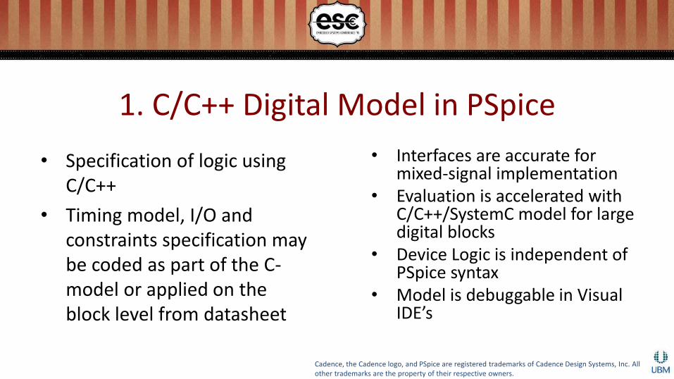
1. C/C++ Digital Model in PSpice
• Specification of logic using C/C++
• Timing model, I/O and constraints specification may be coded as part of the C-model or applied on the block level from datasheet
• Interfaces are accurate for mixed-signal implementation
• Evaluation is accelerated with C/C++/SystemC model for large digital blocks
• Device Logic is independent of PSpice syntax
• Model is debuggable in Visual IDE’s
Cadence, the Cadence logo, and PSpice are registered trademarks of Cadence Design Systems, Inc. All other trademarks are the property of their respective owners.

1. C/C++ Digital Model in PSpice…
• Next: Implementing PWM Block as a Digital behavioral block
Cadence, the Cadence logo, and PSpice are registered trademarks of Cadence Design Systems, Inc. All other trademarks are the property of their respective owners.

Install Model
void __cdecl installpspPWMControl(void* pRef) {fp_descSetVersion(pRef, "1.2");fp_descSetName(pRef, "PSPPWMCONTROL");fp_descSetCreateDevice(
pRef,&pspPWMControl_CreateDevice);fp_descSetDeleteDevice(
pRef,&pspPWMControl_DeleteDevice);fp_descSetEvaluateDevice(
pRef,&pspPWMControl_EvaluateDevice); }
• Links functions between device and simulator
– Sets function pointers from model dll to PSpice
• Sets version and Model Name
• Allows multiple devices to be installed from the same dll
Cadence, the Cadence logo, and PSpice are registered trademarks of Cadence Design Systems, Inc. All other trademarks are the property of their respective owners.

Create Instance
pspPWMControl::pspPWMControl(const char* pInstName, void*pRef) {
mRef = pRef;
mInstName = pInstName;
mPortCount = 18;
mInputPortCount = 17; }
• Creates a new device instance
• Instance Name and Reference set by PSpice
• Port counts set by Device Model
Cadence, the Cadence logo, and PSpice are registered trademarks of Cadence Design Systems, Inc. All other trademarks are the property of their respective owners.

Set Parameter Values
mDigSimFreq = fp_GetParamValueDbl("DIGFREQ");
mDigSimTimeStep = 1.0 / mDigSimFreq;
//Device Specific Initialization
mPER = (int)fp_GetParamValueDbl("PER");
mDutyCycle = fp_GetParamValueDbl("D");
• Get Parameter values from PSpice by nameo Simulator options
o Global parameters set up in design
Cadence, the Cadence logo, and PSpice are registered trademarks of Cadence Design Systems, Inc. All other trademarks are the property of their respective owners.

Evaluatebool pspPWMControl::evaluate(double pTicks, PSpiceState* pVectorStates, int pSize) {double lCurrentTime = mDigSimTimeStep*pTicks;double lDelta = pTicks - mPrevTicks;
//Get input Signal LevelsCLK = pVectorStates[0].getLevel();
//if CLK changed from LO to another valueif ((int)prevCLK == pspBit::LO && (int)CLK != pspBit::LO) { lCLKRisingEdge = true; }}
• Evaluate device at any change in inputso Get Current time
o Get input signal levels
o Detect clock edge
Cadence, the Cadence logo, and PSpice are registered trademarks of Cadence Design Systems, Inc. All other trademarks are the property of their respective owners.
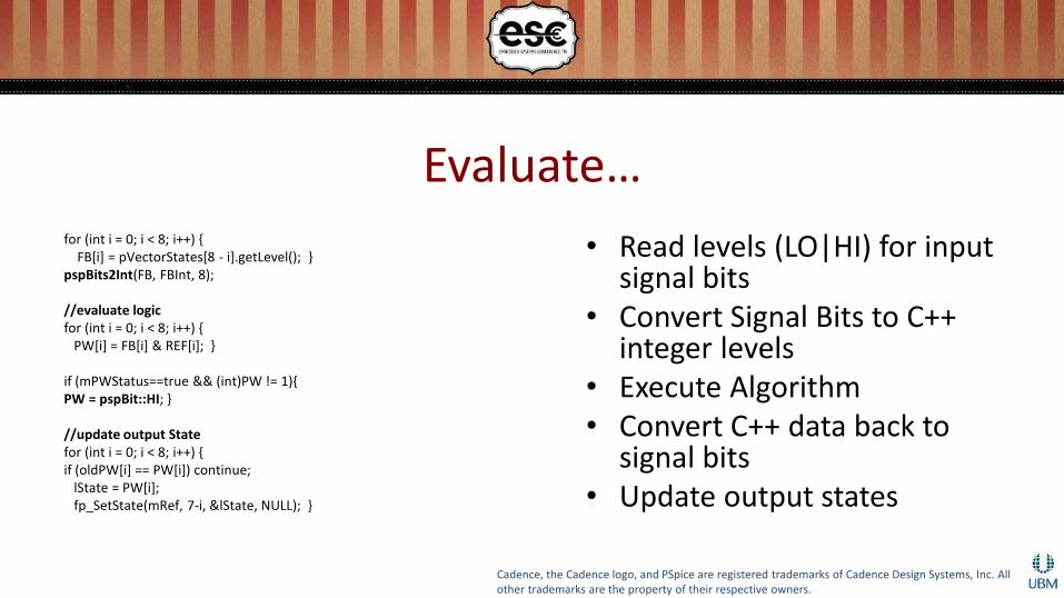
Evaluate…for (int i = 0; i < 8; i++) {
FB[i] = pVectorStates[8 - i].getLevel(); }pspBits2Int(FB, FBInt, 8);
//evaluate logicfor (int i = 0; i < 8; i++) {
PW[i] = FB[i] & REF[i]; }
if (mPWStatus==true && (int)PW != 1){PW = pspBit::HI; }
//update output Statefor (int i = 0; i < 8; i++) {if (oldPW[i] == PW[i]) continue;
lState = PW[i];fp_SetState(mRef, 7-i, &lState, NULL); }
• Read levels (LO|HI) for input signal bits
• Convert Signal Bits to C++ integer levels
• Execute Algorithm• Convert C++ data back to
signal bits• Update output states
Cadence, the Cadence logo, and PSpice are registered trademarks of Cadence Design Systems, Inc. All other trademarks are the property of their respective owners.

Set Delays
PSpiceState lState = (pVectorStates)[0];PSpiceDelay lDelay;lDelay.mMaxDelay = 1e-6;lDelay.mMinDelay = 1e-6;lDelay.mTypDelay = 1e-6;
lState = PW;fp_SetState(mRef, 0, &lState, &lDelay);
• Set Timing Delays• Min/Typ/Max Delays
• Simulator can be setup to run with any 1 value
• Worst-case analysis can be run with min and max delays
• Alternate way is to setup using PSpice Timing Model
Cadence, the Cadence logo, and PSpice are registered trademarks of Cadence Design Systems, Inc. All other trademarks are the property of their respective owners.

Set ConstraintsPSpiceConstraint lConstraint;PSpiceSetupHoldConstraint& lSH =lConstraint.mSetupHold;
lSH.setuptime_hi = 3e-6;lSH.holdtime_hi = 3e-6;strcpy(lSH.mClockName, "CLK");strcpy(lSH.mNetsList->mNetName, "FB1");
PSpiceWidthConstraint& lWidth = lConstraint.mWidth;
strcpy(lWidth.mInputNode, "FB1");lWidth.min_low = 30e-6;lWidth.min_high = 50e-6;
fp_setConstraint(mRef, &lConstraint);
• Set Digital constraints• Setup-Hold
• Pulse Width
• Frequency
• Alternate way is to use Digital CONSTRAINT device in PSpice
Cadence, the Cadence logo, and PSpice are registered trademarks of Cadence Design Systems, Inc. All other trademarks are the property of their respective owners.

C/C++ Digital Model – from C++ to PSpice
• Code is built into a dll• PSpice lib and Capture
symbol created for the model• LOGICEXP device with
keyword C_MODEL used for specifying C-models
• Model loaded from dll by PSpice at run-time
U1 LOGICEXP( 17, 1 ) DPWR DGND+ CLK + FB7 FB6 FB5 FB4 FB3 FB2 FB1 FB0+ REF7 REF6 REF5 REF4 REF3 REF2 REF1 REF0+ PW+ PWMCONTROL_TIMING IO_STD+ C_MODEL: PSPPWMCONTROL.dll PSPPWMCONTROL
Cadence, the Cadence logo, and PSpice are registered trademarks of Cadence Design Systems, Inc. All other trademarks are the property of their respective owners.

2. MATLAB Algorithmic Model in PSpice
• Implementing Averaging Filter Block as a MATLAB Algorithmic Model
Cadence, the Cadence logo, and PSpice are registered trademarks of Cadence Design Systems, Inc. All other trademarks are the property of their respective owners.

Algorithmic Block Simulation in
Matlab-Simulink
MATLAB Model Block Implementation &
Simulation in
PSpice
Mixed-level Co-simulation in Matlab-
Simulink & PSpice
Mixed-level Simulation in PSpice
Using Device modeling API with MathWorks Algorithms
Algorithmic Abstraction Implementation
Cadence, the Cadence logo, and PSpice are registered trademarks of Cadence Design Systems, Inc. All other trademarks are the property of their respective owners.

MATLAB Algorithmic module
Use MATLAB Coder Generate C Code
Use Microsoft Visual Studio
Add PSpice Adapter and embed code
inside PSpice behavioral block
Compile code to generate PSpice-
DMI compatible dll
Use OrCAD CaptureInstantiate device as a macro-model
Run PSpice simulation and verify results
High-level Flow for using MATLAB blocks using PSpice Device
Modeling API
Cadence, the Cadence logo, and PSpice are registered trademarks of Cadence Design Systems, Inc. All other trademarks are the property of their respective owners.

MATLAB Filter algorithm and generated C code using MATLAB Coder
• Example of Averaging Filter– http://www.mathworks.com/help/coder
/examples/averaging-filter.html#zmw57dd0e162
• Generated C Code from MATLAB Coder
Cadence, the Cadence logo, and PSpice are registered trademarks of Cadence Design Systems, Inc. All other trademarks are the property of their respective owners.

Embed MATLAB C Code in PSpice Behavioral Device
• VCVS (Voltage Controlled Voltage Source)
• Independent Voltage Source• More suitable for discontinuous
derivatives
y=f(x)
Matlab
Function
N1
N2
N3
N4
f(x)*V(N3-N4)
Nodes and Branches
•Node N1
•Node N2
•Node N3
•Node N4
•Branch B1
N1 N2 N3 N4 B1 RHS
N1 1
N2 -1
B1 1 -1 -f’(x) f’(x)Cadence, the Cadence logo, and PSpice are registered trademarks of Cadence Design Systems, Inc. All other trademarks are the property of their respective owners.

MATLAB Model State Variables
static double buffer[16];double averaging_filter(const double x, double* buffer) {double y;double dv0[15];
/* Scroll the buffer */memcpy(&dv0[0], &buffer[0], 15U * sizeof(double));memcpy(&buffer[1], &dv0[0], 15U * sizeof(double));
• Persistent Matlab Variable (State variables) moved to PSpice Model State
Cadence, the Cadence logo, and PSpice are registered trademarks of Cadence Design Systems, Inc. All other trademarks are the property of their respective owners.

PSpice Model State Management
•Inner Iteration on current State
Incr0
•Increment to next state as the previous time point has converged
Incr1
•Decrement to previous State as last time point convergence failed
decr1
•Decrement to 2nd previous State as last time point convergence failed
Decr2
Cadence, the Cadence logo, and PSpice are registered trademarks of Cadence Design Systems, Inc. All other trademarks are the property of their respective owners.

Setup for PSpice Evaluation Statescase ININIT:averaging_filter_init(sv.x);nonConv = true;break;case INPRDCT: {double xDiff = sv.x[0] - sv.x[1];double yDiff = sv.y[0] - sv.y[1];if (abs(xDiff) > 0.0) {mGain = yDiff / xDiff;yValue = mGain * (xValue - sv.x[0]); }break; }case INNORM: {
sv.y[0] = yValue = averaging_filter(xValue, sv.x);mGain = yValue / xValue;
break; }
• Initialization of device structures
• Predictor
• Normal Evaluation
Cadence, the Cadence logo, and PSpice are registered trademarks of Cadence Design Systems, Inc. All other trademarks are the property of their respective owners.

Time Step Control
double pspAveragingFilterDevice::Trunc() {
double freq = fp_getParameterValue(“FREQ”);
double delta = fp_getDelta();
if (delta > 1.0/freq) {
double lValDelta = fabs((sv.x[0] - sv.x[1])) /
(fabs(sv.x[0]));
if (lValDelta > 0.1){
lReturnValue = delta / (1+lValDelta);
} }
return lReturnValue; }
• Device-Level– Adaptive
– Fixed
• Global
Cadence, the Cadence logo, and PSpice are registered trademarks of Cadence Design Systems, Inc. All other trademarks are the property of their respective owners.

MATLAB Algorithmic Model – from C++ to PSpice
• Code is built into a dll
• PSpice lib and Capture symbol created for the model
• Y device with keyword CMI used for specifying C-models
• Model loaded from dll by PSpice at run-time
Y_AVGFILTER OUTPUT 0 NOISY_INPUT 0 CMI pspMatlabDemoModels.dllAvgFilter
.model AvgFilter CMIPSPAVERAGINGFILTER+ pw=.5
Cadence, the Cadence logo, and PSpice are registered trademarks of Cadence Design Systems, Inc. All other trademarks are the property of their respective owners.

MATLAB PSpice
Algorithm Transfer to PSpice Circuit
Model
Cadence, the Cadence logo, and PSpice are registered trademarks of Cadence Design Systems, Inc. All other trademarks are the property of their respective owners.

Complete System Simulation
Cadence, the Cadence logo, and PSpice are registered trademarks of Cadence Design Systems, Inc. All other trademarks are the property of their respective owners.

Time
0s 0.2ms 0.4ms 0.6ms 0.8ms 1.0ms 1.2ms 1.4ms 1.6ms 1.8ms 2.0ms 2.2ms 2.4ms 2.6ms 2.8ms 3.0ms 3.2ms 3.4ms 3.6ms 3.8ms 4.0ms
V(VOUT)
0V
5V
10V
0s 0.2ms 0.4ms 0.6ms 0.8ms 1.0ms 1.2ms 1.4ms 1.6ms 1.8ms 2.0ms 2.2ms 2.4ms 2.6ms 2.8ms 3.0ms 3.2ms 3.4ms 3.6ms 3.8ms 4.0ms
CLK
U1.REF2
Simulation Results – output voltage(variation with duty cycle)
Cadence, the Cadence logo, and PSpice are registered trademarks of Cadence Design Systems, Inc. All other trademarks are the property of their respective owners.

3. SystemC Behavioral Model in PSpice
• Implementing PWM Block as a SystemC block
Cadence, the Cadence logo, and PSpice are registered trademarks of Cadence Design Systems, Inc. All other trademarks are the property of their respective owners.

Design Flow
Digital Logic implemented only as a C++ functional
block – no timing information
Timing information added as PSpice/C++ delays
Digital Logic implemented as a SystemC functional
block, with built-in timing
SystemC logic replaced with CPU having
embedded software
Cadence, the Cadence logo, and PSpice are registered trademarks of Cadence Design Systems, Inc. All other trademarks are the property of their respective owners.

SystemC Flow – How it works?
Communicating with PSpice
Running on SystemC Simulator
Digital-C++ wrapper Module
Analog Behavioral
Devices
LOGICEXPDevice
Physical Devices
SystemC Block
PSpice Simulator
Cadence, the Cadence logo, and PSpice are registered trademarks of Cadence Design Systems, Inc. All other trademarks are the property of their respective owners.

SystemC Module Definition
#include <systemc.h>
SC_MODULE(pspSysCFIR) {sc_in<bool> clk;sc_in<sc_logic> reset;sc_in<sc_int<16>> input;sc_out<sc_int<16>> output;
SC_CTOR(pspSysCFIR) {SC_CTHREAD(entry, clk.pos());void entry(); };
• Define Module name
• Define Interface Signals
• Define constructor and entry method
Cadence, the Cadence logo, and PSpice are registered trademarks of Cadence Design Systems, Inc. All other trademarks are the property of their respective owners.

Reading inputs from PSpice
reset = pVectorStates[1].getLevel();
for (int i = 0; i < 16; i++) {inputBits[i] =
pVectorStates[i+2].getLevel(); }
sc_int<16> lValue;
pspBits2Array(inputBits, lValue, 16);
siginput.write(lValue);
• Read input signals
• Create SystemC variables for input signals
• Write to SystemC Block
Cadence, the Cadence logo, and PSpice are registered trademarks of Cadence Design Systems, Inc. All other trademarks are the property of their respective owners.

Evaluate SystemC Block
if (sc_pending_activity()) {
if (pTicks > mPrevTicks) {
sc_start(pTicks - mPrevTicks, SC_PS); }
else {
sc_start(0, SC_PS); }
• sc_start to execute the module till specified time
• pTicks is received from PSpice Simulator
Cadence, the Cadence logo, and PSpice are registered trademarks of Cadence Design Systems, Inc. All other trademarks are the property of their respective owners.

Send output to PSpice
lValue = m_pspSysCFIR->output.read();Int2pspBits(lValue, outputBits, 16);
lState = outputBits[i];fp_SetState(mRef, i, &lState, &lDelay);
• Read values from SystemC block output
• Write to output Signal bits
• Send updated State to PSpice Simulator
Cadence, the Cadence logo, and PSpice are registered trademarks of Cadence Design Systems, Inc. All other trademarks are the property of their respective owners.

System Models Timing
• System Models may be at any level of abstraction
• Accuracy is maintained by PSpice at the interface
Cadence, the Cadence logo, and PSpice are registered trademarks of Cadence Design Systems, Inc. All other trademarks are the property of their respective owners.

4. VerilogA-ADMS Compact Device Model in PSpice
• Implementing a VerilogA-ADMS VBIC Model as a PSpice Compact Device
Cadence, the Cadence logo, and PSpice are registered trademarks of Cadence Design Systems, Inc. All other trademarks are the property of their respective owners.

Verilog-A definition for VBIC Modelmodule vbic(c,b,e,s)
inout c,b; // external nodes
inout e,s; // external nodes
branch (b ,e ) b_be; // base-emit
branch (b ,c ) b_bc; // base-coll
parameter real tnom = 27.0 `P(info="nominal parameter measurement temperature " unit="C");
parameter real rcx = 0.0 from[0.0:inf]`P(info="extrinsic collector resistance " unit="Ohm");
analog begin
Tini = `TABS+tnom;
` Vrth = V(b_rth);
Tdev = $temperature+dtemp+Vrth;
Tdev = Tdev-`TABS;
if (Tdev<tmin)
Tdev = tmin;
• Module name and external node names
• Node definitions
• Branch definitions
• Parameter definitions
• Device Behavior
Cadence, the Cadence logo, and PSpice are registered trademarks of Cadence Design Systems, Inc. All other trademarks are the property of their respective owners.

VerilogA-ADMS translation to PSpice
• admsXml used to translate Verilog-A files to PSpice CMI models
• Script for automatic translation and build of CMI dll– <SPB
hierarchy>\tools\pspice\api\bin\buildADMSProject.bat <path to Verilog-A file>
– Runs admsXml, using PSpice xml filters, and generates the code files
– Also generates a Makefile to build a PSpice-CMI compatible dll
– Runs nmake to build the code into a dll
• VBICSELFT.va translated to:– vbicload.cpp
– vbicdefs.h
– vbicsetup.cpp
– vbictemp.cpp
– PSpiceAdapter.cpp
…
Cadence, the Cadence logo, and PSpice are registered trademarks of Cadence Design Systems, Inc. All other trademarks are the property of their respective owners.

VerilogA-ADMS Simulation in PSpice
Cadence, the Cadence logo, and PSpice are registered trademarks of Cadence Design Systems, Inc. All other trademarks are the property of their respective owners.

Summary
• PSpice® system model extensions enable modeling of large mixed-signal ICs in PCB simulation enabling simulation of entire PCB
• PSpice analog C/C++ extensions with VerilogA-ADMS configurations enable modeling of new technology device compact models into PSpice simulator
Cadence, the Cadence logo, and PSpice are registered trademarks of Cadence Design Systems, Inc. All other trademarks are the property of their respective owners.