Modelamiento en PSS®E de redes con gran participación de...
58
© Siemens AG 2012. All rights reserved. Modelamiento en PSS®E de redes con gran participación de EERR Siemens AG IC SG SE PTI www.siemens.com/power-technologies
Transcript of Modelamiento en PSS®E de redes con gran participación de...

© Siemens AG 2012. All rights reserved.
Modelamiento en PSS®E de redes
con gran participación de EERR
Siemens AG
IC SG SE PTI
www.siemens.com/power-technologies
IC SG SE PTI
© Siemens AG 2012. All rights reserved.
2012-09 Page 2
© Siemens AG 2012. All rights reserved.
Contents
PTI – Overview
Network Consulting – Overview
Software
PSS®E
PSS®SINCAL
IC SG SE PTI
© Siemens AG 2012. All rights reserved.
2012-09 Page 3
PTI Overview
© Siemens AG 2012. All rights reserved.

IC SG SE PTI
© Siemens AG 2012. All rights reserved.
2012-09 Page 4
Siemens Power Technologies International Complete portfolio for public/industrial/commercial power systems
Pow
er
tr
ansm
issio
n
Pow
er
genera
tion
Pow
er
dis
trib
ution
Renew
able
s
Oil
& G
as
industr
y
Meta
ls &
Min
ing
industr
y
Chem
icals
in
dustr
y
Auto
motive
industr
y
Pulp
& P
aper
industr
y
Oth
er
Cem
ent
in
dustr
y Complete scope of
T&D trainings
Products
Systems
Smart grid
Special topics
Certification
Power Academy TD
State-of-the-art
software tools for
E-Transmission
E-Distribution
Pipe networks
Network data
management
Software Solutions
Comprehensive
competences
Grid structure and
configuration
Grid performance
Disturbance
investigations
Network Consulting

IC SG SE PTI
© Siemens AG 2012. All rights reserved.
2012-09 Page 5
Siemens PTI office
Houston
Schenectady
Manchester Erlangen (HQ)
Bogotá
Trondheim
Istanbul
The Hague
Karachi Mumbai Mexico City
São Paulo
Abu Dhabi
Toronto Vienna Minneapolis
San Jose
Buenos Aires
Shanghai
Moscow
Denver
Lagos
Madrid
Siemens PTI – Offices Worldwide presence for our customers
Siemens PTI founded in 1956
Headquarter (HQ)
in Erlangen, Germany
Global leader in transmission
planning software
2000+ customers
600+ projects p.a.
200+ trainings p.a.
Did you know?
23 Siemens PTI offices
world-wide
130+ Consultants
Renowned experts
Profound experiences

IC SG SE PTI
© Siemens AG 2012. All rights reserved.
2012-09 Page 6
Network Consulting
Overview
© Siemens AG 2012. All rights reserved.
IC SG SE PTI
© Siemens AG 2012. All rights reserved.
2012-09 Page 7
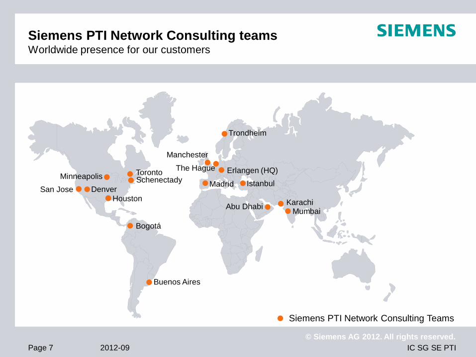
Siemens PTI Network Consulting teams Worldwide presence for our customers
Siemens PTI Network Consulting Teams
Houston
Schenectady
Manchester
Erlangen (HQ)
Bogotá
Trondheim
Istanbul
The Hague
Karachi Mumbai
Abu Dhabi
Toronto Minneapolis
San Jose
Buenos Aires
Madrid Denver

IC SG SE PTI
© Siemens AG 2012. All rights reserved.
2012-09 Page 8
Siemens PTI Network Consulting portfolio Complete set of system analysis, design and optimization studies
Dynamic system
studies
Transient system
studies
Protection and control
system studies
Power quality system
studies
Technical-economical
system studies
4178
5 kV
A
140
kVA
140
kVA
140
kVA
140
kVA
140
kVA
140
kVA
140
kVA
140
kVA
140
kVA
140
kVA
140
kVA
140
kVA
140
kVA
140
kVA
140
kVA
140
kVA
140
kVA
140
kVA
140
kVA
140
kVA
140
kVA
140
kVA
140
kVA
140
kVA
140
kVA
140
kVA
140
kVA14
0 kV
A
140
kVA
140
kVA
140
kVA
140
kVA
140
kVA
140
kVA
140
kVA
140
kVA
140
kVA
140
kVA
140
kVA 14
0 kV
A
140
kVA
140
kVA
140
kVA
140
kVA
140
kVA
140
kVA
140
kVA
140
kVA
140
kVA
140
kVA
140
kVA
140
kVA
140
kVA
140
kVA
140
kVA
140
kVA
140
kVA
140
kVA
140
kVA
140
kVA
140
kVA
140
kVA
140
kVA
140
kVA
140
kVA
140
kVA
140
kVA
140
kVA
140
kVA
140
kVA
140
kVA
140
kVA
140
kVA
140
kVA
140
kVA
140
kVA
140
kVA
140
kVA
140
kVA
140
kVA
140
kVA
140
kVA
140
kVA
140
kVA
140
kVA
140
kVA
140
kVA
140
kVA
140
kVA
140
kVA
140
kVA
140
kVA
140
kVA
140
kVA
140
kVA
140
kVA
140
kVA
140
kVA
140
kVA
140
kVA
140
kVA
140
kVA
140
kVA
140
kVA
140
kVA
140
kVA
140
kVA
140
kVA
140
kVA
140
kVA
140
kVA
140
kVA
140
kVA
140
kVA
140
kVA
140
kVA
140
kVA
140
kVA
140
kVA
140
kVA
140
kVA
140
kVA
140
kVA
140
kVA
140
kVA
140
kVA
140
kVA
140
kVA
140
kVA
140
kVA
140
kVA
140
kVA
140
kVA
140
kVA
140
kVA
140
kVA
140
kVA
140
kVA
140
kVA
140
kVA
140
kVA
140
kVA
140
kVA
140
kVA
140
kVA
140
kVA
140
kVA
140
kVA
140
kVA
140
kVA
140
kVA
140
kVA
140
kVA
140
kVA
140
kVA
140
kVA
140
kVA
140
kVA
140
kVA
140
kVA
140
kVA
140
kVA
140
kVA
140
kVA
140
kVA
140
kVA
140
kVA
140
kVA
140
kVA
140
kVA
140
kVA
140
kVA
140
kVA
140
kVA
140
kVA
140
kVA
140
kVA
140
kVA
500
kVA
500
kVA
500
kVA
500
kVA
500
kVA
500
kVA
500
kVA
500
kVA
500
kVA
500
kVA
500
kVA
500
kVA
500
kVA
500
kVA
1000
kVA
1000
kVA
1000
kVA
1000
kVA
1000
kVA
1000
kVA
1000
kVA
1000
kVA
1000
kVA
1000
kVA
NS
33
1
99
,4 %
NS
33
0
99
,4 %
NS
32
9
99
,4 %
NS
32
8
99
,4 %
NS
32
7
99
,4 %
NS
32
6
99
,4 %
NS
32
5
99
,2 %
NS
32
4
99
,1 %
NS
32
3
99
,1 %
NS
32
2
99
,1 %
NS
32
1
99
,1 %
NS
32
0
99
,1 %
NS
31
9
99
,1 %
NS
31
8
99
,2 %
NS
31
7
99
,3 %
NS
31
6
98
,8 %
NS
31
5
98
,8 %
NS
31
4
99
,0 %
NS
31
3
99
,0 %
NS
31
2
99
,0 %
NS
31
1
98
,9 %
NS
31
0
98
,9 %
NS
30
9
98
,8 %
NS
30
8
98
,8 %
NS
30
7
98
,8 %
NS
30
6
98
,8 %
NS
30
5
98
,9 %N
S3
04
98
,8 %
NS
30
3
98
,8 %
NS
30
2
99
,6 %
NS
30
1
99
,6 %
NS
30
0
99
,6 %
NS
29
9
99
,4 %
NS
29
8
99
,4 %
NS
29
7
99
,5 %
NS
29
6
98
,9 %
NS
29
5
99
,3 %
NS
29
4
99
,2 %
NS
29
3
99
,1 % N
S2
92
99
,1 %
NS
29
1
99
,1 %
NS
29
0
99
,0 %
NS
28
9
98
,9 %
NS
28
8
99
,0 %
NS
28
7
98
,9 %
NS
28
6
98
,9 %
NS
28
5
98
,9 %
NS
28
4
99
,0 %
NS
28
3
99
,0 %
NS
28
2
99
,1 %
NS
28
1
99
,2 %
NS
28
0
99
,1 %
NS
27
9
99
,3 %
NS
27
8
99
,4 %
NS
27
7
99
,5 %
NS
27
6
99
,5 %
NS
27
5
99
,6 %
NS
27
4
99
,7 %
NS
27
3
99
,8 %
NS
27
2
99
,6 %
NS
27
1
99
,1 %
NS
27
0
99
,2 %
NS
26
9
99
,3 %
NS
26
8
99
,2 %
NS
26
7
99
,2 %
NS
26
6
99
,3 %
NS
26
5
99
,3 %
NS
26
4
99
,2 %
NS
26
3
99
,5 %
NS
26
2
99
,4 %
NS
26
1
99
,4 %
NS
26
0
99
,4 %
NS
25
9
99
,2 %
NS
25
8
99
,3 %
NS
25
7
99
,7 %
NS
25
6
99
,5 %
NS
25
5
99
,3 %
NS
25
4
99
,3 %
NS
25
3
98
,9 %
NS
25
2
99
,4 %
NS
25
1
99
,4 %
NS
25
0
99
,5 %
NS
24
9
99
,8 %
NS
24
8
99
,7 %
NS
24
7
99
,6 %
NS
24
6
99
,6 %
NS
24
5
99
,5 %
NS
24
4
99
,5 %
NS
24
3
99
,8 %
NS
24
2
99
,8 %
NS
24
1
99
,8 %
NS
24
0
99
,9 %
NS
23
9
99
,9 %
NS
23
8
99
,8 %
NS
23
7
99
,8 %
NS
23
6
99
,6 %
NS
23
5
99
,7 %
NS
23
4
99
,7 %
NS
23
2
99
,8 %
NS
23
1
99
,9 %
NS
23
0
99
,9 %
NS
22
8
99
,6 %
NS
22
7
99
,6 %
NS
22
6
99
,2 %
NS
22
5
99
,4 %
NS
22
4
99
,3 %
NS
22
3
99
,1 %
NS
22
2
99
,1 %
NS
22
1
99
,0 %
NS
22
0
99
,0 %
NS
21
9
98
,9 %
NS
21
8
99
,0 %
NS
21
7
99
,5 %
NS
21
6
99
,4 %
NS
21
5
99
,1 %
NS
21
4
99
,1 %
NS
21
3
99
,1 %
NS
21
2
99
,2 %
NS
21
1
99
,4 %
NS
21
0
99
,3 %
NS
20
9
99
,2 %
NS
20
8
99
,0 %
NS
20
7
99
,0 %
NS
20
6
99
,0 %
NS
20
5
99
,0 %
NS
20
4
99
,0 %
NS
20
3
99
,0 %
NS
20
2
99
,0 %
NS
20
1
99
,0 %
NS
20
0
99
,0 %
NS
19
9
99
,0 %
NS
19
8
99
,0 %
NS
19
7
99
,0 %
NS
19
6
99
,3 %
NS
19
5
99
,1 %
NS
19
4
99
,1 %
NS
19
3
99
,2 %
NS
19
2
99
,2 %
NS
19
1
99
,1 %
NS
19
0
99
,1 %
NS
18
9
99
,0 %
NS
18
8
99
,0 %
NS
18
7
99
,0 %
NS
18
6
99
,0 %
NS
18
5
99
,0 %
NS
18
4
99
,0 %
NS
18
3
99
,0 %
NS
18
2
99
,0 %
NS
18
1
99
,1 %
NS
18
0
99
,3 %
NS
17
9
99
,5 %
NS
17
8
99
,4 %
NS
17
7
99
,4 %
NS
17
6
99
,3 %
NS
17
5
99
,1 %
NS
17
4
99
,1 %
NS
17
3
99
,1 %
NS
17
2
99
,2 %
NS
17
1
99
,3 %
NS
17
0
99
,4 %
NS
16
9
99
,4 %
NS
16
8
99
,5 %
NS
16
7
99
,5 %
NS
16
6
99
,6 %
NS
16
5
99
,7 %
NS
16
4
99
,2 %
NS
16
3
99
,7 %
NS
16
2
99
,2 %
NS
16
1
99
,3 %
NS
16
0
99
,4 %
NS
15
9
99
,5 %
NS
15
8
99
,6 %
NS
15
7
99
,7 %
NS
15
6
99
,9 %
NS
15
5
99
,8 %
NS
15
4
99
,8 %
NS
15
3
99
,8 %
NS
15
2
99
,9 %
Su
bS
tati
on
10
0,0
%
K3
1
98
,9 %
K3
0
98
,9 %
K2
9
99
,0 %
K2
8
99
,0 %
K2
7
99
,5 %
K2
6
99
,5 %
K2
5
99
,5 %
K2
4
99
,5 %
K2
3
99
,6 %
K2
2
99
,6 %
K2
1
99
,7 %
K2
0
99
,7 %
K1
9
99
,7 %
K1
8
99
,7 %
K1
7
99
,8 %
K1
6
99
,8 %
K1
5
99
,9 %
K1
4
99
,8 %
K1
3
99
,7 %
K1
2
99
,7 %
K1
1
99
,7 %
K1
0
99
,7 %
K9
99
,7 %
K8
99
,7 %
Steady-state system
studies
0%
20%
40%
60%
80%
100%
120%
GIS HIS AIS
Replacement of Equipm.
Outage Cost System
Unscheduled Maint.System
Scheduled Maint.System
Scheduled Maint. BoP
Ground acquisition costs
Balance of Plant
System Cost
Co
st
of
Ow
ne
rsh
ipC
os
t o
f A
cq
uis
itio
n
0
100
200
300
400
500
600
700
800
900
1000
1100
switchgearcabletransformer
kV
10 µs 20 µs 30 µs
BIL
0
100
200
300
400
500
600
700
800
900
1000
1100
switchgearcabletransformer
kV
10 µs 20 µs 30 µs
BIL

IC SG SE PTI
© Siemens AG 2012. All rights reserved.
2012-09 Page 9
Network Consulting portfolio – Portfolio elements Comprehensive consulting offerings built from 18 portfolio elements
Business case
studies
Energy market
studies
Asset management
and due diligence
Controller a. machine
measurements,
modeling a. analysis
Power electronics
modeling and
analysis
System control and
automation concepts
Instrument
transformer analysis
Power quality meas-
urements, analysis
and filter design
Interference and
EM field analysis
Earthing system
measurements and
design
Insulation
coordination
studies
Transient studies Dynamic system
analysis
Energy efficiency
audits
Neutral grounding
studies
Network structure
development Network analysis
Protection system
design and
coordination
IC SG SE PTI
© Siemens AG 2012. All rights reserved.
2012-09 Page 10
Network Consulting
Case studies
© Siemens AG 2012. All rights reserved.

IC SG SE PTI
© Siemens AG 2012. All rights reserved.
2012-09 Page 11
Characteristics of island and off-grid
power supply systems
high costs for electricity
low supply reliability
Small networks rely on diesel generation
for back-up and stability reasons
Targets of island network operators
Reduction of generation costs
Independency of fuel imports
Adequate level of security of supply
Ecological considerations – becoming
“green”
Initial situation
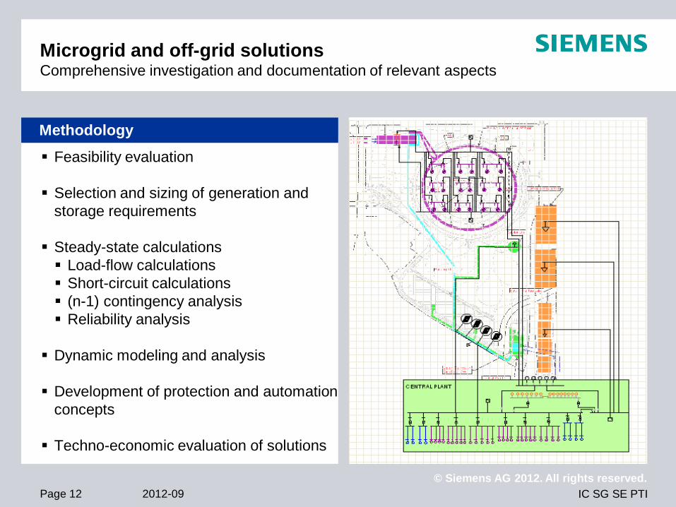
Microgrid and off-grid solutions Design of specialized network concepts with innovative technologies
IC SG SE PTI
© Siemens AG 2012. All rights reserved.
2012-09 Page 12
Feasibility evaluation
Selection and sizing of generation and
storage requirements
Steady-state calculations
Load-flow calculations
Short-circuit calculations
(n-1) contingency analysis
Reliability analysis
Dynamic modeling and analysis
Development of protection and automation
concepts
Techno-economic evaluation of solutions
Methodology
Microgrid and off-grid solutions Comprehensive investigation and documentation of relevant aspects

IC SG SE PTI
© Siemens AG 2012. All rights reserved.
2012-09 Page 13
Technically and economically feasible
design of microgrid network
Optimal generation mix including
requirements for energy storage
Comprehensive concepts including
Electrical network design
Suitable protection concept
Automation and smart grid concepts
Definition of scenarios for deployment of
renewable energy sources
Verification of good network performance
Minimum CAPEX and OPEX
Results
Microgrid and off-grid solutions Solution covering all relevant technical and economic aspects

IC SG SE PTI
© Siemens AG 2012. All rights reserved.
2012-09 Page 14
Customer request for intelligent network
design
Integration of various sub-systems, e.g.
Renewable energy sources
Intelligent loads and building automation
Various management systems
Electromobility
Energy storage
Development of future-oriented, innovative
network concepts ensuring
Reliability of supply
Sustainability
Flexibility
Economical efficiency
Initial situation
Design of smart grid network concepts Definition of functional requirements and design of innovative concepts

IC SG SE PTI
© Siemens AG 2012. All rights reserved.
2012-09 Page 15
Design and validation of network concept
and performance requirements
Comprehensive set of studies, e.g.
Equipment sizing and losses
Reactive power and voltage control
Short-circuit currents
Harmonics
Reliability and security of supply
Development of integrated solutions
considering e.g.
Distribution automation concepts
Communication requirements
Functional specification of integrated
smart grid operation center
Analysis of network operation strategies
Methodology
Design of smart grid network concepts
Detailed investigations and development of possible solutions

IC SG SE PTI
© Siemens AG 2012. All rights reserved.
2012-09 Page 16
Integrated smart grid concept
Performance analysis ensuring
Adequate network performance
Sustainability and minimum losses
Intelligent control and automation concepts
Application of most innovative technologies
using
Primary components
Communication technologies
Smart grid applications and functionality
Efficient network operation
Optimal overall concept for innovative
developments
Results
Design of smart grid network concepts Integrated overall solution with validated performance

IC SG SE PTI
© Siemens AG 2012. All rights reserved.
2012-09 Page 17
Customer Arup Consult
Country US
Completed 2012
Analysis of technical, economical and environmental
feasibility
Improved energy efficiency and maximized energy savings
Proven network performance
Apple Campus 2, New Headquarter (US) Designing Microgrid solution for new Apple Campus
Design of campus microgrid
Determination of energy storage requirements
Verification of performance in island and grid connected
operation mode
Sizing of conventional and renewable generation
Determination of storage requirements
Minimizing load shedding incidents
Calculation of investment and operation costs while
considering environmental aspects in power generation
Requirements
Scope
Customer Benefits
IC SG SE PTI
© Siemens AG 2012. All rights reserved.
2012-09 Page 18
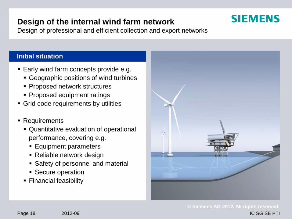
Early wind farm concepts provide e.g.
Geographic positions of wind turbines
Proposed network structures
Proposed equipment ratings
Grid code requirements by utilities
Requirements
Quantitative evaluation of operational
performance, covering e.g.
Equipment parameters
Reliable network design
Safety of personnel and material
Secure operation
Financial feasibility
Initial situation
Design of the internal wind farm network Design of professional and efficient collection and export networks
IC SG SE PTI
© Siemens AG 2012. All rights reserved.
2012-09 Page 19
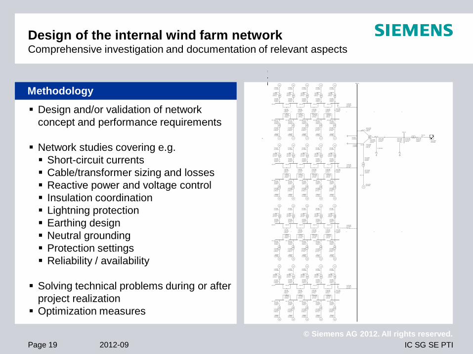
Design and/or validation of network
concept and performance requirements
Network studies covering e.g.
Short-circuit currents
Cable/transformer sizing and losses
Reactive power and voltage control
Insulation coordination
Lightning protection
Earthing design
Neutral grounding
Protection settings
Reliability / availability
Solving technical problems during or after
project realization
Optimization measures
Methodology
Design of the internal wind farm network Comprehensive investigation and documentation of relevant aspects
101,7 %
101,5 %
101,6 %
101,4 %
101,5 %
101,3 %
101,4 %
101,2 %
101,7 %
101,9 %
101,7 %
101,9 %
101,6 %
101,8 %
101,5 %
101,7 %
101,4 %
101,5 %
101,0 %
101,0 %
101,0 %
103,7 %
100,0 %
0,0 °
100,2 %
101,7 %
101,6 %
101,7 %
101,5 %
101,6 %
101,4 %
101,5 %
101,3 %
101,4 %
101,2 %
101,7 %
101,9 %
101,7 %
101,9 %
101,6 %
101,8 %
101,5 %
101,7 %
101,4 %
101,5 %
101,7 %
101,5 %
101,6 %
101,4 %
101,5 %
101,3 %
101,4 %
101,2 %
101,7 %
101,9 %
101,7 %
101,9 %
101,6 %
101,8 %
101,5 %
101,7 %
101,4 %
101,5 %
101,7 %
101,6 %
101,7 %
101,5 %
101,6 %
101,4 %
101,5 %
101,3 %
101,4 %
101,2 %
101,7 %
101,9 %
101,7 %
101,9 %
101,6 %
101,8 %
101,5 %
101,7 %
101,4 %
101,5 %
101,7 %
101,7 %
101,6 %
101,7 %
101,6 %
G
G
GG
-242,97 MW
-6,65 MVAr
G
3,35 MW
0,20 MVAr
-3,35 MW
-0,20 MVAr
0,577 kA
3,35 MW
0,04 MVAr
0,058 kA
G
3,35 MW
0,20 MVAr
-3,35 MW
-0,20 MVAr
0,577 kA
3,35 MW
0,04 MVAr
0,058 kA
-6,69 MW
-0,12 MVAr
0,115 kA
G
3,35 MW
0,20 MVAr
-3,35 MW
-0,20 MVAr
0,578 kA
3,35 MW
0,04 MVAr
0,058 kA
-10,04 MW
-0,21 MVAr
0,173 kA
G
3,35 MW
0,20 MVAr
-3,35 MW
-0,20 MVAr
0,579 kA
3,35 MW
0,04 MVAr
0,058 kA
-13,38 MW
-0,28 MVAr
0,231 kA
-3,35 MW
-0,04 MVAr
0,058 kA
-3,35 MW
-0,20 MVAr
0,576 kA
3,35 MW
0,04 MVAr
0,058 kA
G
3,35 MW
0,20 MVAr
-3,35 MW
-0,20 MVAr
0,576 kA
3,35 MW
0,04 MVAr
0,058 kA
G
3,35 MW
0,20 MVAr
-6,69 MW
-0,12 MVAr
0,115 kA
-3,35 MW
-0,20 MVAr
0,576 kA
3,35 MW
0,04 MVAr
0,058 kA
G
3,35 MW
0,20 MVAr
-10,04 MW
-0,21 MVAr
0,173 kA
-3,35 MW
-0,20 MVAr
0,577 kA
3,35 MW
0,04 MVAr
0,058 kA
G
3,35 MW
0,20 MVAr
-13,38 MW
-0,29 MVAr
0,231 kA
-3,35 MW
-0,20 MVAr
0,578 kA
3,35 MW
0,04 MVAr
0,058 kA
G
3,35 MW
0,20 MVAr
16,67 MW
0,39 MVAr
0,288 kA
-33,38 MW
-0,74 MVAr
0,577 kA
-253,47 MW
67,62 MVAr
0,973 kA
244,07 MW
46,15 MVAr
0,954 kA
242,97 MW
6,65 MVAr
0,369 kA
-244,06 MW
-46,15 MVAr
0,954 kA
-37,66 MVAr
G
3,35 MW
0,20 MVAr
-3,35 MW
-0,20 MVAr
0,577 kA
3,35 MW
0,04 MVAr
0,058 kA
G
3,35 MW
0,20 MVAr
-3,35 MW
-0,20 MVAr
0,577 kA
3,35 MW
0,04 MVAr
0,058 kA
-3,35 MW
-0,04 MVAr
0,058 kA
G
3,35 MW
0,20 MVAr
-3,35 MW
-0,20 MVAr
0,577 kA
3,35 MW
0,04 MVAr
0,058 kA
-6,69 MW
-0,12 MVAr
0,115 kA
G
3,35 MW
0,20 MVAr
-3,35 MW
-0,20 MVAr
0,578 kA
3,35 MW
0,04 MVAr
0,058 kA
-10,04 MW
-0,21 MVAr
0,173 kA
G
3,35 MW
0,20 MVAr
-3,35 MW
-0,20 MVAr
0,579 kA
3,35 MW
0,04 MVAr
0,058 kA
-13,38 MW
-0,28 MVAr
0,231 kA
-3,35 MW
-0,04 MVAr
0,058 kA
-3,35 MW
-0,20 MVAr
0,576 kA
3,35 MW
0,04 MVAr
0,058 kA
G
3,35 MW
0,20 MVAr
-3,35 MW
-0,20 MVAr
0,576 kA
3,35 MW
0,04 MVAr
0,058 kA
G
3,35 MW
0,20 MVAr
-6,69 MW
-0,12 MVAr
0,115 kA
-3,35 MW
-0,20 MVAr
0,576 kA
3,35 MW
0,04 MVAr
0,058 kA
G
3,35 MW
0,20 MVAr
-10,04 MW
-0,21 MVAr
0,173 kA
-3,35 MW
-0,20 MVAr
0,577 kA
3,35 MW
0,04 MVAr
0,058 kA
G
3,35 MW
0,20 MVAr
-13,38 MW
-0,29 MVAr
0,231 kA
-3,35 MW
-0,20 MVAr
0,578 kA
3,35 MW
0,04 MVAr
0,058 kA
G
3,35 MW
0,20 MVAr
16,67 MW
0,39 MVAr
0,288 kA
-33,38 MW
-0,74 MVAr
0,577 kA
G
3,35 MW
0,20 MVAr
-3,35 MW
-0,20 MVAr
0,577 kA
3,35 MW
0,04 MVAr
0,058 kA
G
3,35 MW
0,20 MVAr
-3,35 MW
-0,20 MVAr
0,577 kA
3,35 MW
0,04 MVAr
0,058 kA
-6,69 MW
-0,12 MVAr
0,115 kA
G
3,35 MW
0,20 MVAr
-3,35 MW
-0,20 MVAr
0,578 kA
3,35 MW
0,04 MVAr
0,058 kA
-10,04 MW
-0,21 MVAr
0,173 kA
G
3,35 MW
0,20 MVAr
-3,35 MW
-0,20 MVAr
0,579 kA
3,35 MW
0,04 MVAr
0,058 kA
-13,38 MW
-0,28 MVAr
0,231 kA
-3,35 MW
-0,04 MVAr
0,058 kA
-3,35 MW
-0,20 MVAr
0,576 kA
3,35 MW
0,04 MVAr
0,058 kA
G
3,35 MW
0,20 MVAr
-3,35 MW
-0,20 MVAr
0,576 kA
3,35 MW
0,04 MVAr
0,058 kA
G
3,35 MW
0,20 MVAr
-6,69 MW
-0,12 MVAr
0,115 kA
-3,35 MW
-0,20 MVAr
0,576 kA
3,35 MW
0,04 MVAr
0,058 kA
G
3,35 MW
0,20 MVAr
-10,04 MW
-0,21 MVAr
0,173 kA
-3,35 MW
-0,20 MVAr
0,577 kA
3,35 MW
0,04 MVAr
0,058 kA
G
3,35 MW
0,20 MVAr
-13,38 MW
-0,29 MVAr
0,231 kA
-3,35 MW
-0,20 MVAr
0,578 kA
3,35 MW
0,04 MVAr
0,058 kA
G
3,35 MW
0,20 MVAr
16,67 MW
0,39 MVAr
0,288 kA
-33,38 MW
-0,74 MVAr
0,577 kA
G
3,35 MW
0,20 MVAr
-3,35 MW
-0,20 MVAr
0,577 kA
3,35 MW
0,04 MVAr
0,058 kA
G
3,35 MW
0,20 MVAr
-3,35 MW
-0,20 MVAr
0,577 kA
3,35 MW
0,04 MVAr
0,058 kA
-3,35 MW
-0,04 MVAr
0,058 kA
G
3,35 MW
0,20 MVAr
-3,35 MW
-0,20 MVAr
0,577 kA
3,35 MW
0,04 MVAr
0,058 kA
-6,69 MW
-0,12 MVAr
0,115 kA
G
3,35 MW
0,20 MVAr
-3,35 MW
-0,20 MVAr
0,578 kA
3,35 MW
0,04 MVAr
0,058 kA
-10,04 MW
-0,21 MVAr
0,173 kA
G
3,35 MW
0,20 MVAr
-3,35 MW
-0,20 MVAr
0,579 kA
3,35 MW
0,04 MVAr
0,058 kA
-13,38 MW
-0,28 MVAr
0,231 kA
-3,35 MW
-0,04 MVAr
0,058 kA
-3,35 MW
-0,20 MVAr
0,576 kA
3,35 MW
0,04 MVAr
0,058 kA
G
3,35 MW
0,20 MVAr
-3,35 MW
-0,20 MVAr
0,576 kA
3,35 MW
0,04 MVAr
0,058 kA
G
3,35 MW
0,20 MVAr
-6,69 MW
-0,12 MVAr
0,115 kA
-3,35 MW
-0,20 MVAr
0,576 kA
3,35 MW
0,04 MVAr
0,058 kA
G
3,35 MW
0,20 MVAr
-10,04 MW
-0,21 MVAr
0,173 kA
-3,35 MW
-0,20 MVAr
0,577 kA
3,35 MW
0,04 MVAr
0,058 kA
G
3,35 MW
0,20 MVAr
-13,38 MW
-0,29 MVAr
0,231 kA
-3,35 MW
-0,20 MVAr
0,578 kA
3,35 MW
0,04 MVAr
0,058 kA
G
3,35 MW
0,20 MVAr
16,67 MW
0,39 MVAr
0,288 kA
-33,38 MW
-0,74 MVAr
0,577 kA
G
127,00 MW
9,00 MVAr
-127,00 MW
-9,01 MVAr
21,900 kA
126,44 MW
2,32 MVAr
2,190 kA
-2,80 MW
-1,30 MVAr
-3,40 MW
-1,30 MVAr
253,46 MW
-29,96 MVAr
0,947 kA
-123,04 MW
-1,02 MVAr
2,131 kA
-130,43 MW
-1,68 MVAr
2,260 kA
G
3,35 MW
0,20 MVAr
-3,35 MW
-0,20 MVAr
0,577 kA
3,35 MW
0,04 MVAr
0,058 kA
-3,35 MW
-0,04 MVAr
0,058 kA
G
3,35 MW
0,20 MVAr
-3,35 MW
-0,20 MVAr
0,577 kA
3,35 MW
0,04 MVAr
0,058 kA
-3,35 MW
-0,04 MVAr
0,058 kA

IC SG SE PTI
© Siemens AG 2012. All rights reserved.
2012-09 Page 20
Comprehensive analysis of technical
performance
Optimized system configuration
Validated technical system performance
Voltage profile
Equipment loading
Short-circuit currents
Selective fault clearing
Personnel safety
Reliability
Basis for reliable and efficient operation
Results
Design of the internal wind farm network Sound solution with validated technical and economical performance

IC SG SE PTI
© Siemens AG 2012. All rights reserved.
2012-09 Page 21
Grid code compliance investigation Validation of operational performance at the point of common coupling
Existing power system
“Background noise” in operational
parameters
Grid code regulations
Network concept for wind farm
Impact on operational parameters
Requirements
Assessment and verification of grid code
compliance
Enhancement of wind farm preliminary
design where necessary
Consideration of specific project
limitations and boundary conditions
Basis for grid connection approval
Initial situation Dynamic requirement for generation output
in fault conditions
Reactive power output requirement

IC SG SE PTI
© Siemens AG 2012. All rights reserved.
2012-09 Page 22
Simulation and calculation of wind farm
performance at the point of common
coupling
Investigation of compliance with
respective technical criteria in grid code
and/or bilateral agreements
Network analyses covering e.g.
Load flow and reactive power balance
Harmonics
Voltage fluctuation / flicker
Transient and dynamic stability
(incl. fault-ride-through performance)
Mitigation or enhancement measures
where necessary
Methodology
Grid code compliance investigation Comprehensive investigation covering all relevant aspects
Impedance scan over frequency
Harmonic voltage spectrum
Background contribution
Wind farm contribution
Admissible planning levels
IC SG SE PTI
© Siemens AG 2012. All rights reserved.
2012-09 Page 23
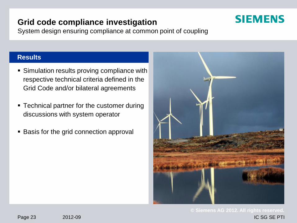
Simulation results proving compliance with
respective technical criteria defined in the
Grid Code and/or bilateral agreements
Technical partner for the customer during
discussions with system operator
Basis for the grid connection approval
Results
Grid code compliance investigation System design ensuring compliance at common point of coupling

IC SG SE PTI
© Siemens AG 2012. All rights reserved.
2012-09 Page 24
Comprehensive modeling of wind turbines
in a specific simulation software
Basis for detailed wind farm investigations
Requirements
Software model of the wind turbine
generator for simulation purposes
Implementation of specific wind turbine
generator performance requirements
Development and management of
models
Necessary sales asset for the
manufacturers
Initial situation
Wind turbine modeling Models for wind turbine generators and wind farms as basis for studies

IC SG SE PTI
© Siemens AG 2012. All rights reserved.
2012-09 Page 25
Modeling of wind turbine generators in the
PSS® Product Suite
(also other software tools, e.g.
PowerFactory of DIgSILENT)
Comprising different aspects, e.g.
Mathematical representation of energy
conversion processes in equivalent
block diagrams
Implementation of control concepts
Aggregation of turbine models together
with park controller into the complete wind
farm model
Methodology
Wind turbine modeling Development and verification of detailed turbine and controller models
IC SG SE PTI
© Siemens AG 2012. All rights reserved.
2012-09 Page 26
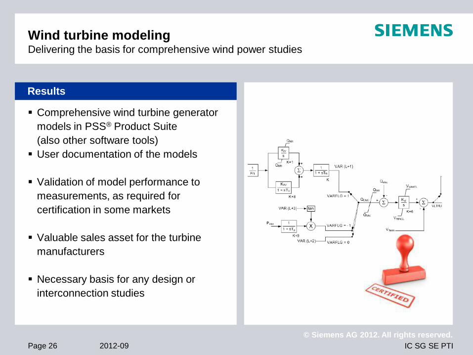
Comprehensive wind turbine generator
models in PSS® Product Suite
(also other software tools)
User documentation of the models
Validation of model performance to
measurements, as required for
certification in some markets
Valuable sales asset for the turbine
manufacturers
Necessary basis for any design or
interconnection studies
Results
Wind turbine modeling Delivering the basis for comprehensive wind power studies

IC SG SE PTI
© Siemens AG 2012. All rights reserved.
2012-09 Page 27
Network Consulting
Portfolio Elements
© Siemens AG 2012. All rights reserved.

IC SG SE PTI
© Siemens AG 2012. All rights reserved.
2012-09 Page 28
Siemens PTI – Network Consulting Network analysis
Network Analysis covers the analysis of electrical power systems
based on power system calculations including the dimensioning of
primary equipment.
Typical network analysis studies include
Data collection and digital network model for steady state
calculation
Analysis of load flow, short circuit and reliability calculations
Dimensioning of electrical equipment, e.g. cable, overhead lines,
busbars, switchgears
Analysis of technical power system parameters (e.g. voltage drop,
short circuit levels)
Definition of system operation modes
Verification of system design
Analysis of planning criteria, e.g. voltage profile, equipment
loading, (n-1)-compliance, reliability thresholds
Scope

IC SG SE PTI
© Siemens AG 2012. All rights reserved.
2012-09 Page 29
Siemens PTI – Network Consulting Dynamic system analysis
Dynamics in transmission and industry networks
Determination and analysis of relevant stability aspects
Modeling and simulation of system dynamic behavior
Inter- and intra-area oscillation investigations
Analysis of power angle and voltage stability aspects
Definition of appropriate location and settings for stabilizing devices
(e.g. FACTS)
Definition of decoupling schemes in industrial networks and power
plants
Investigation of frequency stability in island networks
Motor start-up investigations
Dynamics of rotating machines
Voltage and power/frequency control
Verification of controller settings
Investigation of turbine-generator shaft stresses (SSR, SSTI)
Scope

IC SG SE PTI
© Siemens AG 2012. All rights reserved.
2012-09 Page 30
Siemens PTI – Network Consulting System control and automation concepts
System Control and Automation Concepts
Development of wide area protection and control schemes
Special protection schemes based on PMUs and relays for critical
local system states
Distribution automation and islanding
Development of load shedding schemes
Dynamic simulation and analysis of power grids and interacting
protection and communication systems
System Security Assessment and Enhancement
SIGUARD – Intelligent, dynamic power system measurement,
analysis, protection and control solutions
Combined power system measurement and model based analysis
Observing dynamics with time-synchronized PMUs
Predicting critical dynamic system states and proposal of measures
Protection system audits for speed and selectivity
Scope

IC SG SE PTI
© Siemens AG 2012. All rights reserved.
2012-09 Page 31
Siemens PTI – Network Consulting Power electronics modeling and analysis
Modeling and analysis of controllers of active grid equipment like
generators, FACTS, HVDC equipment, large electronic consumers
Development, adaption, parameterization, identification, verification,
testing of
Classical generator control (e.g. AVR, PSS, speed governor)
FACTS elements (e.g. SVC, Statcom, TCSC, UPFC)
HVDC equipment (e.g. HVDC classic, HVDC plus)
Realtime simulator grid models
Large electronic consumers (e.g. VSDs like Robicon or
SIMOVERT)
Large dynamic load groups (e.g. LNG, cement, paper, chemical
plants)
Renewable energy generators (e.g. wind, PV)
Scope

IC SG SE PTI
© Siemens AG 2012. All rights reserved.
2012-09 Page 32
Siemens PTI – Network Consulting Controller and machine measurements, modeling and analysis
Measurements, modeling and analysis of
Controllers,
e.g. automatic voltage regulator (AVR), power system stabilizer
(PSS), governors, or control systems for turbines, power plant
performance, FACTS, HVDC, HVDC Plus
Machine parameters of synchronous generators and induction
machines
Objectives
Control of system voltage and frequency, damping of oscillations
Development, coding and validation of standard or user defined
models for controllers, parameter identification
Design, optimization and location of PSS and power oscillation
damping (POD) devices
Assessment of grid code compliance
Scope

IC SG SE PTI
© Siemens AG 2012. All rights reserved.
2012-09 Page 33
Siemens PTI – Network Consulting Asset management and due diligence
Key process modules
Systematic consideration of technical and economic performance
indicators
Assessment of component importance by use of probabilistic
reliability analyses
Increasing efficiency of network operation by:
Prioritization of network equipment according to importance and
condition
Adaptation of preventive maintenance strategies
Adaptation of preventive replacement strategies
Solutions
RCAM Reliability Centered Asset Management
ARMA Asset Risk Mitigation Analysis
Scope

IC SG SE PTI
© Siemens AG 2012. All rights reserved.
2012-09 Page 34
Siemens PTI – Network Consulting Business case studies
Business cases studies support customers in their business
decisions by providing dynamic business case calculations
Typical business case study support utilities, grid operators, industrial
enterprises regarding:
Grid concession (evaluation of assets, technical-economical
analysis, investment plan)
Economical evaluation of variants for network development
CAPEX and OPEX analysis and review
Due diligence analysis
Analysis and review of tariff structures
Legal boundary condition (e.g. incentive regulation)
Scope

IC SG SE PTI
© Siemens AG 2012. All rights reserved.
2012-09 Page 35
PSS Software Suite
PSS®E
© Siemens AG 2012. All rights reserved.
IC SG SE PTI
© Siemens AG 2012. All rights reserved.
2012-09 Page 36
Concerns of a Power System Planner
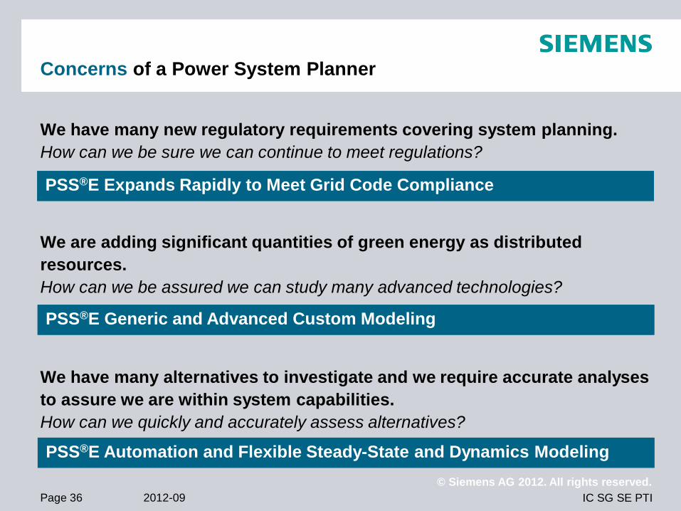
We have many new regulatory requirements covering system planning.
How can we be sure we can continue to meet regulations?
We are adding significant quantities of green energy as distributed
resources.
How can we be assured we can study many advanced technologies?
We have many alternatives to investigate and we require accurate analyses
to assure we are within system capabilities.
How can we quickly and accurately assess alternatives?
The Siemens PTI Solution PSS®E Expands Rapidly to Meet Grid Code Compliance
The Siemens PTI Solution PSS®E Generic and Advanced Custom Modeling
The Siemens PTI Solution PSS®E Automation and Flexible Steady-State and Dynamics Modeling
IC SG SE PTI
© Siemens AG 2012. All rights reserved.
2012-09 Page 37
PSS®E
World-Class Advanced Modularity
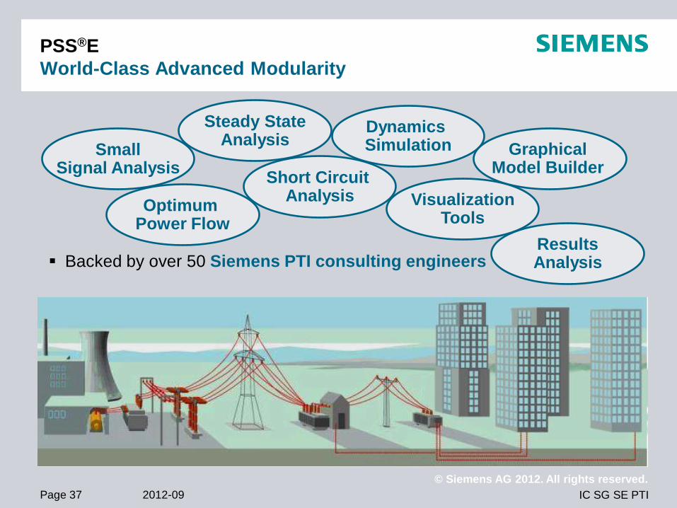
Backed by over 50 Siemens PTI consulting engineers
Steady State Analysis
Dynamics Simulation Small
Signal Analysis Graphical
Model Builder
Optimum Power Flow
Short Circuit Analysis
Results Analysis
Visualization Tools
IC SG SE PTI
© Siemens AG 2012. All rights reserved.
2012-09 Page 38
Co
mm
on
In
form
ati
on
Mo
de
l (C
IM)
IEC
61
97
0 &
61
96
8
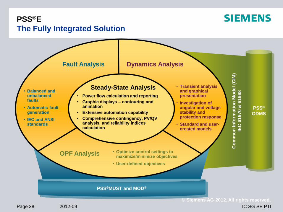
PSS®
ODMS
PSS®MUST and MOD®
Steady-State Analysis
• Power flow calculation and reporting
• Graphic displays – contouring and animation
• Extensive automation capability
• Comprehensive contingency, PV/QV analysis, and reliability indices calculation
• Balanced and unbalanced faults
• Automatic fault generation
• IEC and ANSI standards
• Transient analysis and graphical presentation
• Investigation of angular and voltage stability and protection response
• Standard and user-created models
PSS®E
The Fully Integrated Solution
Fault Analysis Dynamics Analysis
• Optimize control settings to maximize/minimize objectives
• User-defined objectives
OPF Analysis

IC SG SE PTI
© Siemens AG 2012. All rights reserved.
2012-09 Page 39
PSS®E
Highlights
Comprehensive model library for modeling all types of equipment, including
models of emerging technologies such as FACTS devices and wind powered
generation.
Capability to create user-written models – If you cannot find dynamic models
that suit your equipment, you can create your own user-written models in a
high-level language like FORTRAN.
Variety of manufacturer-specific and generic models of wind turbines and
their controls.
Powerful and easy to use plot facility for plotting results of dynamic
simulation.
Graphical method to create user models, Eigen-value analysis.

IC SG SE PTI
© Siemens AG 2012. All rights reserved.
2012-09 Page 40
PSS®E
Integrated Program
One entry point …
Network data
One-line diagrams
OPF data
Dynamics data
Model data
Plot page
From a single
application!

IC SG SE PTI
© Siemens AG 2012. All rights reserved.
2012-09 Page 41
Understand Your Network
Various One-Click Reports
Network Condition
Voltage profile
Transmission lines and transformer
loading
Automatic contingency violation
Machine loadings
Total generation
Total load
Write a program
Interface Condition
Tie line flow/loading
Total area interchange
Network Reduction
Outside of your control area
Reduce level of details when necessary

IC SG SE PTI
© Siemens AG 2012. All rights reserved.
2012-09 Page 42
Siemens PTI
Exports Geospatial Data to Google Earth®

IC SG SE PTI
© Siemens AG 2012. All rights reserved.
2012-09 Page 43
PSS®E
Summary
Description
Transmission system simulation software offering
advanced modules for analysis of electrical
networks
Scope
Used by power system engineers worldwide for
planning and operations activities in the off-line
and on-line simulation environments
Customer Benefits
Designed for improved reliability while saving
infrastructure costs
Comprehensive modeling capabilities enable
sophisticated analyses and accuracies while
saving man-hours
Contingency Solution
Corrective Action Solution

IC SG SE PTI
© Siemens AG 2012. All rights reserved.
2012-09 Page 44
PSS®E –
Overview
Description
Transmission system simulation software offering
advanced modules for analysis of electrical
networks.
Scope
Used by power system engineers worldwide for
both the planning and operations activities in the
off-line and on-line simulation environments.
Customer benefits
Designs for improved reliability while saving
infrastructure costs
Comprehensive modeling capabilities enable
sophisticated analyses and accuracies while
saving man hours
Frequency of overloads Frequency of overloads

IC SG SE PTI
© Siemens AG 2012. All rights reserved.
2012-09 Page 45
Wind Power Plant Studies
Wind power plant (basic) design studies
Focus is on the wind power plant itself, detailed representation of the power plant
internals.
Wind power plant interconnection studies
Focus is on the transmission system interconnection of the wind power plant.
Only the terminal behavior is important, limited aggregation may be performed.
Transmission studies containing wind generators
Only approximate behavior is required, aggregation usually performed.

IC SG SE PTI
© Siemens AG 2012. All rights reserved.
2012-09 Page 46
Typical Wind Power Studies With PSS®E
Steady-State Studies
Power flow (network design, reactive control range, losses)
Short circuit
Transmission network planning in presence of large-scale wind power
Transient Stability
Fault ride-through
Voltage/reactive power control performance
Voltage stability
Frequency control performance
Transmission network interconnection studies in presence of large-scale wind
power
IC SG SE PTI
© Siemens AG 2012. All rights reserved.
2012-09 Page 47
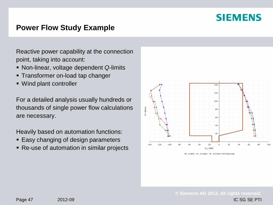
Power Flow Study Example
Reactive power capability at the connection
point, taking into account:
Non-linear, voltage dependent Q-limits
Transformer on-load tap changer
Wind plant controller
For a detailed analysis usually hundreds or
thousands of single power flow calculations
are necessary.
Heavily based on automation functions:
Easy changing of design parameters
Re-use of automation in similar projects
0
20
40
60
80
100
120
140
-140 -120 -100 -80 -60 -40 -20 0 20 40 60 80 100
Q CP (MW)
PC
P (
Mva
r)
U=90% U=100% U=110% Grid Code
IC SG SE PTI
© Siemens AG 2012. All rights reserved.
2012-09 Page 48
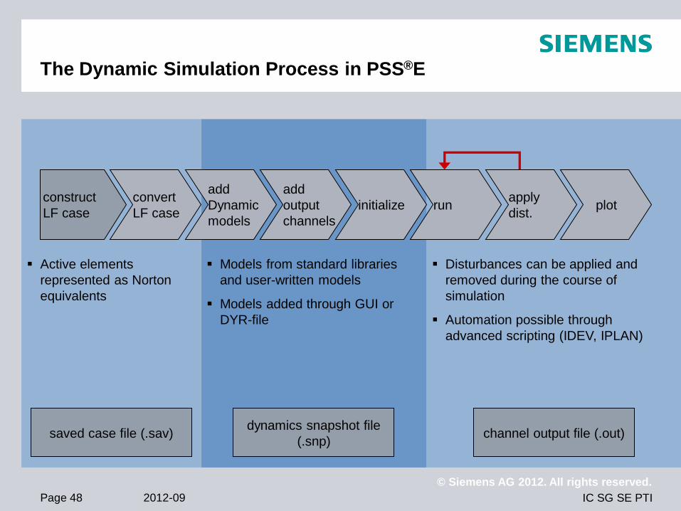
The Dynamic Simulation Process in PSS®E
construct
LF case
convert
LF case
add
Dynamic
models
add
output
channels
initialize run apply
dist. plot
Active elements
represented as Norton
equivalents
Models from standard libraries
and user-written models
Models added through GUI or
DYR-file
Disturbances can be applied and
removed during the course of
simulation
Automation possible through
advanced scripting (IDEV, IPLAN)
saved case file (.sav) dynamics snapshot file
(.snp) channel output file (.out)

IC SG SE PTI
© Siemens AG 2012. All rights reserved.
2012-09 Page 49
Dynamic Model Structure for Wind Machines –
Model Slots
The ‘wind machine’ equipment category allows a hierarchy of models to be
added:
Generator/Converter – This is be the current injection model
Electrical Control
Mechanical System/Control
Pitch Control
Aerodynamics
Wind Gust/Ramp
Auxiliary Control
These model ‘slots’ offer a flexible hierarchy and enable a modular approach of
wind models
Usage not enforced, e.g. coding complete model into the generator

IC SG SE PTI
© Siemens AG 2012. All rights reserved.
2012-09 Page 50
Use a similar existing model with data adjusted to represent the new equipment
Use the traditional way to build a user-written model in PSS®E
Create your own user-drawn model using the GMB
What if there is no suitable PSS®E model for my
equipment ?

IC SG SE PTI
© Siemens AG 2012. All rights reserved.
2012-09 Page 51
Introduction of GMB
What is GMB (1)?
Graphic Model Builder (GMB) is available as a separate PSS®E add-on that allows
PSS®E users to graphically build user models for dynamic simulation without having
the need to write and compile high level language programs (e.g. FORTRAN).
GMB works with PSS®E, Rev. 30.3.2 and newer.
“User-drawn” models are in addition to the known PSS®E standard and “User-written”
models.

IC SG SE PTI
© Siemens AG 2012. All rights reserved.
2012-09 Page 52
Introduction of GMB
What is GMB (2)?
GMB uses the Microsoft Visio®
graphical interface to draw and
simulate dynamic models of exciters
and turbine governors, with other
model categories to be added in
future releases.
IC SG SE PTI
© Siemens AG 2012. All rights reserved.
2012-09 Page 53
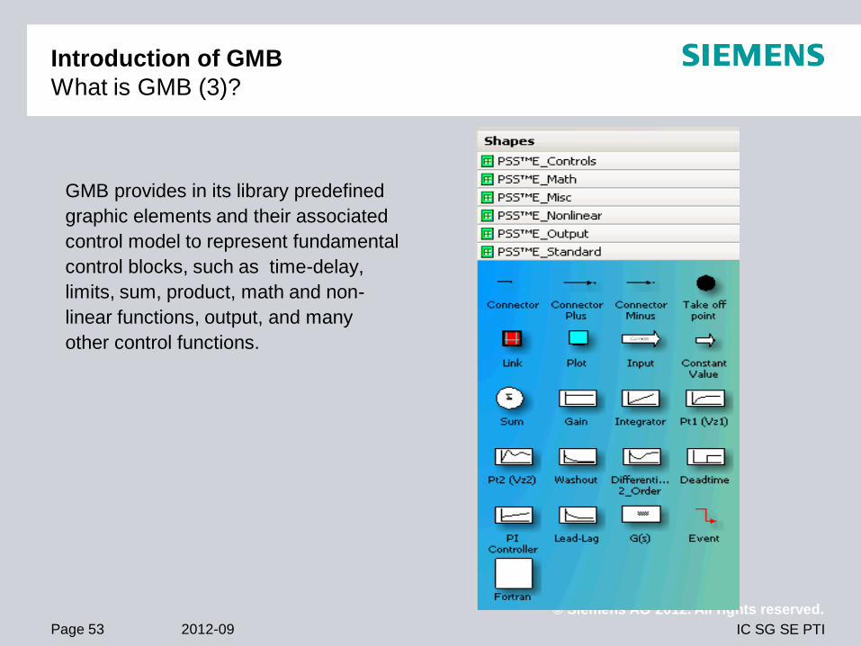
Introduction of GMB
What is GMB (3)?
GMB provides in its library predefined
graphic elements and their associated
control model to represent fundamental
control blocks, such as time-delay,
limits, sum, product, math and non-
linear functions, output, and many
other control functions.

IC SG SE PTI
© Siemens AG 2012. All rights reserved.
2012-09 Page 54
Introduction of GMB
What is GMB (4)?
You are free to add FORTRAN statements to your model, which are then interpreted
by GMB without the need of an additional compiler.
The total number of user-defined models (traditional FORTRAN based user-defined
models plus user-defined models created using GMB) that can be handled in
PSS®E is defined in Table P-1 of the PSS®E Program Operation Manual Volume I.

IC SG SE PTI
© Siemens AG 2012. All rights reserved.
2012-09 Page 55
Introduction of GMB
How does the GMB work ?
After having designed a model, the user
must enter the necessary parameters for the
different blocks via masks and add event
signals and monitor plots for validating the
model.
After standalone tests, the new model can be used directly in PSS®E (only if the
BOSL.dll is available) as a GMB-Macro without the need of compilation.
IC SG SE PTI
© Siemens AG 2012. All rights reserved.
2012-09 Page 56
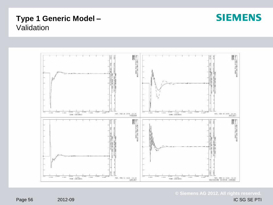
Type 1 Generic Model –
Validation

IC SG SE PTI
© Siemens AG 2012. All rights reserved.
2012-09 Page 57
Thank you for your attention!
© Siemens AG 2011. All rights reserved.

IC SG SE PTI
© Siemens AG 2012. All rights reserved.
2012-09 Page 58
© Siemens AG 2012. All rights reserved.
Diego Murcia
Consultant
Siemens AG, IC SG SE PTI NC TRS
Freyeslebenstrasse 1
91058 Erlangen
Germany
Phone: +49 9131 – 7 33878
Fax: +49 9131 – 7 325159
E-mail: [email protected]
www.siemens.com/power-technologies