
Model T Camshaft Design - mtfctulsa.com
17
1 Model T Camshaft Model T Camshaft Design Design By By Larry Young Larry Young Presented at Sunflower Presented at Sunflower Crankers Crankers Winter Winter Clinic, Hutchinson, KS, Jan. 22, 2011 Clinic, Hutchinson, KS, Jan. 22, 2011 I first came to this clinic with Fred Houston about 10 years ago to discuss our cam project. At that time, only reground T cams were available. We had confirmed that a cam with near stock characteristics gave better performance than a reground cam, so we knew we needed some new cams. I asked Fred – “Who will we get to design them?” and Fred said “You”. I had no previous experience, so went through a crash course. Steve Coniff was instrumental through discussions and by sending a copy of a very good book (Turkish) to learn from. From that point, I was curious to learn more about cam design and how Ford cam designs evolved throughout the flathead era. George DeAngelis provided the original drawings for the Ford flathead cams from the Ford archives. I also collaborated with Steve Coniff to design a couple of one-off cams for his Montana 500 effort. One of these was in Tom Carnegie’s winning car in 2009. I also got into vintage road racing in a Triumph TR3. That provided the incentive to do my first OHV designs I’ve sold about 50 of these to other Triumph TR3 and 4 vintage racers. You can find more information about our Model T Cam project at: clubs.hemmings.com/clubsites/MTFCTulsa/Cams. Some of my other efforts and a complete history of Ford flathead cam designs can be found at: www.tildentechnologies.com
Transcript of Model T Camshaft Design - mtfctulsa.com

1
Model T Camshaft Model T Camshaft
DesignDesignByBy
Larry YoungLarry Young
Presented at Sunflower Presented at Sunflower CrankersCrankers Winter Winter Clinic, Hutchinson, KS, Jan. 22, 2011Clinic, Hutchinson, KS, Jan. 22, 2011
I first came to this clinic with Fred Houston about 10 years ago to discuss our cam project. At that time, only reground T cams were available. We had
confirmed that a cam with near stock characteristics gave better performance
than a reground cam, so we knew we needed some new cams. I asked Fred –
“Who will we get to design them?” and Fred said “You”. I had no previous
experience, so went through a crash course. Steve Coniff was instrumental through discussions and by sending a copy of a very good book (Turkish) to
learn from. From that point, I was curious to learn more about cam design and
how Ford cam designs evolved throughout the flathead era. George DeAngelis
provided the original drawings for the Ford flathead cams from the Ford
archives. I also collaborated with Steve Coniff to design a couple of one-off cams for his Montana 500 effort. One of these was in Tom Carnegie’s winning
car in 2009. I also got into vintage road racing in a Triumph TR3. That provided
the incentive to do my first OHV designs I’ve sold about 50 of these to other
Triumph TR3 and 4 vintage racers.
You can find more information about our Model T Cam project at:
clubs.hemmings.com/clubsites/MTFCTulsa/Cams.
Some of my other efforts and a complete history of Ford flathead cam designs
can be found at:
www.tildentechnologies.com

2
4 Stoke Engine4 Stoke Engine
The strokes are – intake, compression, power, exhaust
This could be the intake stroke if the piston is going down or exhaust if it is going
up.
Note 2:1 ratio of crank to cam and focus on the cam lobes, so the crank turns
twice for each turn of the cam.

3
Lobe TermsLobe Terms
Model T and all Ford flathead cams are gear driven so they turnscounterclockwise. The Model T stock cam had no ramp, all other Ford flathead
cams had ramps. The new T cams have a small ramp area.

4
Cam LobesCam Lobes
Important graph, keep this picture in mind. This is a snapshot of the cam lobes at TDC on the start of the intake stroke. Note open and close of exhaust and
intake. The difference is the Duration. For most modern engines both valves
will be open at TDC. This is called overlap. The Model T stock, 250, 280 and L-
R have no overlap. Note the centerlines. These are typically at about +/- 55
degrees or +/- 110 crank degrees. The angle between the two lobes is the Lobe Separation Angle. The angle of a line half way between centerlines is the
cam Advance. You can think of advance just like in ignition timing. If we
increase the advance by rotating the picture counterclockwise, then all the
events occur sooner. If the centers are at equal angles, 0 advance, the cam is
said to be straight up. For stock Model T and the 250 and 280 cams, the intake is at 122 crank degrees and the exhaust is at -109 crank degrees. This means
the cam is retarded, since the angle of the line half way between is (122 –
109)/2 = 6.5 degrees to the right. The advance is an important tuning parameter,
since it can be changed using a vernier gear or by drilling the dowel pin holes at a nonstandard angle.

5
Lift CurvesLift Curves
You can look at the lobes, but it is the lift curves that tell the story. These lines were calculated from the original Model T Ford Cam specs. The points were
measured by Fred and I on a NOS cam loaned to us by Steve Coniff. To get
the Ford spec for duration of 218 degrees and open/close angles, the valve
clearance must be set as 0.025. Today, the industry standard quotes timing at
0.050 gross lift. The reason for this is that it measures the duration after the valve is open far enough to start flowing significant air. When comparing cams
with different valve clearance, it would be better to use a standard based on net
lift. For most Ford cams (Model A thru early 1950’s) 0.050 gross lift
corresponds to 0.035 net lift, so I will use that here. The stock model T cam had
188 degrees duration at 0.035 net lift. In a moment, I will show how this compares to other Ford cams.

6
Cam Event ImportanceCam Event Importance
Never Sacrifice Duration for Lift!
• Intake Duration
• Intake Center (Advance)
• Lobe Separation• Exhaust Duration
• Intake Lift• Exhaust Lift
• Intake Close
• Intake Open• Exhaust Open
• Exhaust Close• Intake Lift
• Exhaust Lift
or
When designing a cam, you should keep the relative importance of the events in mind. On the intake stroke, the A/F mixture is sucked in with only atmospheric pressure as the driving force. The exhaust gases are at much higher pressure, so they flow out more easily. For this reason, the intake timing is far more important than exhaust timing. The most important timing event is the intake close. You can think of the air as a spring, which is being drawn down by the piston. The tail of the spring will lag the head of the spring. To capture as much air as possible, the intake valve should close after BDC. The faster the engine spins, the later it should close. For a slow speed engine the intake should close sooner. The intake opening is less important because the piston is near TDC where there is not a lot of travel for each degree of rotation. However, earlier opening causes more overlap and contributes to poor idle and off idle performance. On the exhaust side, the opening is most important. If it opens too soon, then some of the power will be lost out the exhaust pipe. If it opens too late, power will be lost in what are called pumping losses. The exhaust close is less important again because the piston is near TDC, but a late closing will contribute to increased overlap.
The four timing event are far more important than lift. Unfortunately, lift is what most Model T guys look at. There are cams advertised as stock, when they have stock lift, but completely different timing. This is false and misleading advertising in my opinion.
On the right, I’ve reorganized the 4 timing events into a different, but equivalent set of four parameters. The duration is the difference between the close and open. The intake center is the average of the open and close. One set of numbers is easily calculated from the other. The other parameter is the lobe separation, the difference between the centers. The reason for selecting these parameters is that 3 of them are built into the cam, but the intake center can be adjusted during installation of the cam, e.g. by using a gear with different dowel pin holes or a vernier gear. For any given cam, we can use the intake center or the advance for tuning.

7
Cam TradeoffsCam Tradeoffsfrom: from: How to Hop Up Ford and Mercury V8 Engines How to Hop Up Ford and Mercury V8 Engines
From this discussion, it is clear there are tradeoffs in cam design. The largest influence is the intake duration and intake closing or intake center. An earlier
intake close improves low speed performance, while a later close improves high
speed performance. This tradeoff was known even before the Model T was
introduced. This graph comes from a neat little book by Roger Huntington in
1951. The stock cam has intake duration of about 200 (at 0.035 net or 0.050 gross) and the ¾ race had 20 to 25 degrees more. We can expect the same
general behavior for a Model T. Of course, the Model T will not achieve 4000
RPM with a flathead because of its poor flow and low compression.

8
HP HP vsvs DurationDuration
data from: data from: Secrets Secrets -- The Ford Speed and Sport Magazine (1999)The Ford Speed and Sport Magazine (1999)
Our cam project was started around 1999, when Larry Sigworth and Fred Houston collected data on a number of different cams and used an engine
simulator to predict their performance. At that time, there were no new cams
available, only regrinds with intake duration of 235 degrees seat-to-seat or
more. I took the data out of their article and created this graph of average
horsepower vs intake duration. Each dot is one of the cams they simulated and the line is a simple curve fit to the data. The curve fit suggests that a duration of
about 225 degrees would be best. The stock T cam is the point at 218 degrees.
At 225 is the Laurel-Roof and some other antique performance cams. Most of
the regrinds create the cluster of points around 250 degrees. Based on this
data, we decided to design three cams all with a valve lash of 0.010: (1) stock 218 duration and 0.250 lift (2) replica of the Laurel-Roof cam, 225 duration and
0.310 lift and (3) a cam with intermediate duration and 0.280 lift. We used Ford
timing specs for the 250 and 280 and the Laurel-Roof timing specs for it. The
Laurel-Roof timing was actually copied from a Stutz engine.

9
280 Cam Lift Curve280 Cam Lift Curve
Once the duration has been determined, then the cam should be designed for maximum lift. For the 280 cam the duration at 0.035 is set at 195 degrees. We
could get more lift if the slope of the curve were steeper and if the nose part
could curve around and match the closing flank. However, there are some
limitations as shown on the next slide.

10
Size MattersSize Matters
2 sizes of 280 lobeStock lobe at 45 degrees
At the left is a lifter and stock cam lobe at 45 degrees. We have to make sure that the point of contact doesn’t occur off the edge of the lifter. It turns out that
the point of contact is directly related to the slope of the lift curve (previous
slide). The size of the lifter limits the slope of the lift curve.
At the right are two lobes that produce the same 280 lift curve. The
eccentricity determine the curvature of the entire nose portion of the lift curve.
More eccentricity gives a tighter curve and more lift. Unfortunately, the cam has
to slide through the cam bearing holes, which are 1.375 in diameter. A trick
learned from Steve Coniff is that this size limit applies only to the exhaust lobe. The intake lobe can be a bit larger. We used this trick in the design of the 280
cam in order to get more lift. Also, the nose needs to have at least a 1/32 inch
radius to reduce wear. The green lobe with a sharp point would not be practical.
This also explains why a stock cam with a worn down nose cannot be reground
back to a stock profile. If you tried to regrind one, the nose would go to a point like the green lobe. Cam grinders call this “knifing out”. Steve Coniff once had
a cam which he nicknamed the “Gillette” cam, after the maker of razor blades.

11
Some SolutionsSome Solutionsfrom: from: The Fast Ford HandbookThe Fast Ford Handbook
Notching the block
Larger lifters
The limitations just described were well know during the Model T era. These diagrams are from Murray Fahnestock. Due to their larger size, antique
performance cams like the Laurel-Roof required notches in the block in order to
install them. They also required a larger diameter lifter. A replica of the Laurel-
Roof cam and larger lifters are available from Bill Stipe.

12
Model T CamsModel T Cams
�� 250 Improved Stock (250 Improved Stock (StipeStipe))
�� 280 Super280 Super--Power Cam (Power Cam (StipeStipe))
�� LaurelLaurel--Roof (replica)Roof (replica)
�� 250 Chaffin250 Chaffin
�� 280 Chaffin280 Chaffin
�� 305 305 StipeStipe (prototype)(prototype)
�� 290 (proposed)290 (proposed)
�� OHV Cam (proposed)OHV Cam (proposed)
Here are the new Model T cams that are available now and a few that may be available in the near future. The first three were developed in the Cam Project.
Two other cams are available from the Chaffin Garage. Although the Chaffin
cams have the same lift as the two Stipe cams, the valve timing is completely
different. The only thing stock about the Chaffin 250 cam is its lift. There is a
305 cam that Bill Stipe has developed and run in his roadster pickup. He also has a performance .335 cam which runs directly in the block. I’ve also designed
a cam with more than 290 lift, but similar duration to the 280 cam. We are
planning to have one of these for dyno testing. I believe the current Stipe cams
are too aggressive and totally inappropriate for an OHV engine, e.g. Fronty or
Rajo, which will turn over 3000 RPM. I’ve designed a cam strictly for OHV engines. It is less aggressive, but has .320 lift due to a slightly longer duration
On the next few slides I’ll compare these cams to each other and to other Ford
cams.

13
Ford Cams Intake DurationFord Cams Intake Duration
This shows the most important parameter – the intake duration measured at 0.035 net lift. Normally, duration should increase with engine speed, so it is not
surprising that the Model T has the smallest duration. However, you will notice
that the majority of V8 cams (1937-51) had a duration similar to the Model A and
the Model B cam had as much duration as any of the V8 cams. As mentioned,
the 250 Stipe cam was designed to have stock duration and the 280 and Laurel-Roof have slightly more. The duration of the Chaffin cams is similar to the
Laurel-Roof. The proposed 290 is similar to the current 280.

14
Ford Cams Intake CenterFord Cams Intake Center
The next most important parameter is the intake center. Here we notice that the intake center for the Model T is greater than the other Ford flathead cams.
Some people fervently claim that Model T cams should be advance 7.5 degrees
or half a tooth. This would put the intake center close to that of the Model B at
about 115 degrees. During some recent and preliminary dyno work with Mike
Bender and Bill Howell, we found that the 280 Stipe cam did benefit if it is advanced 4 degrees, but 8 degrees was worse than no advance. You have to
remember the picture of the two lobes. When the cam is advanced, all the
events will occur sooner. I believe that 8 degrees is too much for this cam,
because it causes the exhaust valve to open too soon.

15
Ford Cams Lobe SeparationFord Cams Lobe Separation
Remember the picture of the two lobes. Once the intake center is established, the lobe separation determines the center of the exhaust lobe. The lobe
separation angle is measured in cam degrees, so if the intake center is fixed,
increasing the lobe separation by one degree causes the exhaust valve to open
and close two degrees earlier. Normally, lobe separation should be somewhat
less for a higher revving engine. Nevertheless, the Model T cam has a fairly wide lobe separation. With this wide separation, advancing the cam too much
will cause the exhaust valve to open too soon and will not get all the power out
of the charge. The new 290 cam will have a smaller lobe separation, so it
should work well with the intake center closer to that of a Model A or B. The
Chaffin cams have a very small lobe separation, but the intake center is close to the stock position causing the exhaust valve open/close very late, probably too
late for the best performance.
16
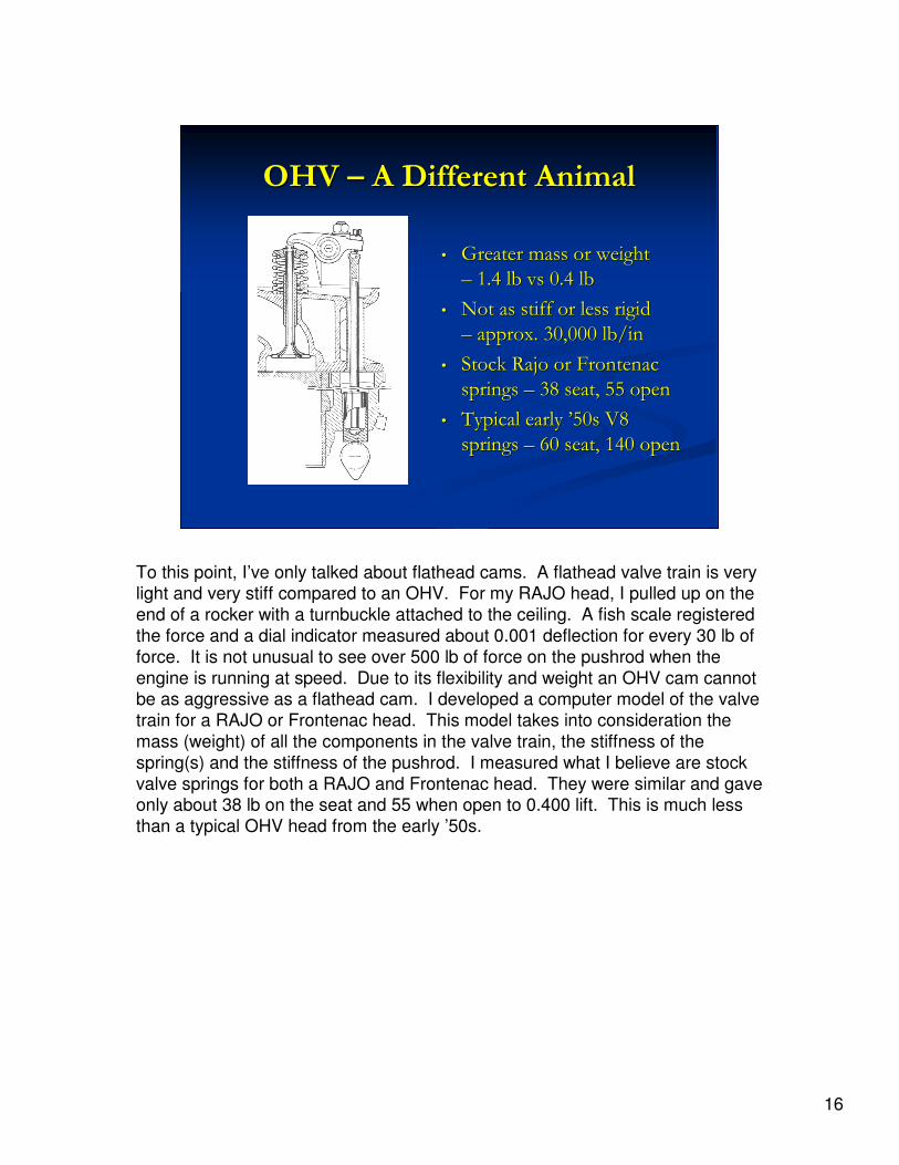
OHV OHV –– A Different AnimalA Different Animal
•• Greater mass or weight Greater mass or weight
–– 1.4 lb 1.4 lb vsvs 0.4 lb0.4 lb
•• Not as stiff or less rigid Not as stiff or less rigid
–– approx. 30,000 lb/inapprox. 30,000 lb/in
•• Stock Stock RajoRajo or Frontenac or Frontenac
springs springs –– 38 seat, 55 open38 seat, 55 open
•• Typical early Typical early ’’50s V8 50s V8
springs springs –– 60 seat, 140 open60 seat, 140 open
To this point, I’ve only talked about flathead cams. A flathead valve train is very light and very stiff compared to an OHV. For my RAJO head, I pulled up on the
end of a rocker with a turnbuckle attached to the ceiling. A fish scale registered
the force and a dial indicator measured about 0.001 deflection for every 30 lb of
force. It is not unusual to see over 500 lb of force on the pushrod when the
engine is running at speed. Due to its flexibility and weight an OHV cam cannot be as aggressive as a flathead cam. I developed a computer model of the valve
train for a RAJO or Frontenac head. This model takes into consideration the
mass (weight) of all the components in the valve train, the stiffness of the
spring(s) and the stiffness of the pushrod. I measured what I believe are stock
valve springs for both a RAJO and Frontenac head. They were similar and gave only about 38 lb on the seat and 55 when open to 0.400 lift. This is much less
than a typical OHV head from the early ’50s.

17
RajoRajo or Frontenacor Frontenac
280 280 StipeStipe CamCam
The model can predict the amount of force between the cam and lifter as the engine is turning at speed. If this force goes to zero, the cam and lifter will
separate. Although it doesn’t fall completely apart at this speed, this is the
beginning of valve float. With the stock springs and a Stipe 280 cam, the engine
could not achieve even 2,000 RPM. With stiffer springs (60 closed, 100 open)
and engine speed of 2,800 RPM could be achieved. With dual springs (60 closed, 140 open) only 3,200 RPM could be reached. I have designed an OHV
cam which is less aggressive and has a bit more duration and about .320 lift.
This will give over 0.450 valve lift. It maintains contact with the lifter to beyond
4,000 RPM with springs that are 60 closed and 140 open. With this much spring
force, a normal Model T cam of 0.75 inch diameter would flex considerably. In order to have a large diameter, the OHV cam will require notches and will run
directly in the block.
Since I know there are many OHV engines that are running the Stipe cams, I will attempt to reconcile these calculations with real life experience. I suspect that
most are using 3:1 gears which will give about 90 mph at 3,000 RPM. Does
anyone actually run there OHV engines to 3,000 RPM? I know of at least one
that runs beyond 3,000, but he doesn’t have a Stipe cam. I also wonder what
type of valve springs are being run. I will find out more when I run my RAJO with the 280 cam and stock (38 closed, 55 open) springs.