MODEL Stormwater Local Design Manual - Official Website · City of Centerville Stormwater Local...
28
MODEL Stormwater Local Design Manual City of Centerville Adopted December 6, 2005
Transcript of MODEL Stormwater Local Design Manual - Official Website · City of Centerville Stormwater Local...

MODEL Stormwater Local
Design Manual
City of Centerville
Adopted December 6, 2005

City of Centerville Stormwater Local Design Manual
i
TABLE OF CONTENTS
1. FORWARD ................................................................................................................... 1
2. GENERAL LEVEL OF SERVICE STANDARDS ........................................................ 1
2.1. DETENTION REQUIREMENTS ............................................................................ 1 2.1.1. Discharge Rates from New Development Projects ...................................... 1 2.1.2. Discharge Rates from Redevelopment Projects .......................................... 2
2.2. CONVEYANCE SYSTEMS .................................................................................. 2 2.2.1. Bridges........................................................................................................... 2 2.2.2. Culverts & Pipe Systems .............................................................................. 2 2.2.3. Inlets (Catch Basins, Yard Inlets, Drop Inlets, Hooded Grate ..... Inlets and Flumes) 3 2.2.4. Inlets (Headwalls, Flared End Sections, etc.) .............................................. 4 2.2.5. Roadside Ditches .......................................................................................... 4 2.2.6. Drainage Channels ....................................................................................... 4
2.3. WATER QUALITY TREATMENT .......................................................................... 4 2.3.1. Water Quality in New Development ............................................................. 4 2.3.2. Water Quality in Redevelopment .................................................................. 5
2.4. CHANNEL PROTECTION ................................................................................... 5 2.4.1. Channel Protection for New Development Projects..................................... 5 2.4.2. Channel Protection for Redevelopment Projects ......................................... 5
2.5. ENERGY DISSIPATION ..................................................................................... 5
3. APPROVED CONSTRUCTION MATERIALS & BMPS ............................................. 6
3.1. CONVEYANCE STRUCTURES ............................................................................ 6 3.1.1. Pipes Under Roads and Within the Public Right-of-Way............................. 6 3.1.2. Other Pipe Systems (as defined above) ...................................................... 6 3.1.3. Channels ....................................................................................................... 7 3.1.4. Inlets .............................................................................................................. 7
3.2. DETENTION PONDS ......................................................................................... 7 3.2.1. Dry Earthen Detention Ponds ....................................................................... 7 3.2.2. Dry Underground Detention Ponds .............................................................. 8 3.2.3. Wet Detention Ponds .................................................................................... 8
3.3. WATER QUALITY BEST MANAGEMENT PRACTICES ........................................... 8 3.3.1. General Application Structural Stormwater Controls ................................... 8 3.3.2. Limited Application Structural Controls ........................................................ 8 3.3.3. Proprietary Structural Controls ..................................................................... 9
3.4. CHANNEL PROTECTION DESIGN....................................................................... 9
4. APPROVED HYDROLOGIC & HYDRAULIC METHODS ........................................ 10
4.1. HYDROLOGIC METHODS ................................................................................ 10 4.1.1. Rational Method .......................................................................................... 10 4.1.2. SCS Method ................................................................................................ 10
4.2. HYDRAULIC METHODS ................................................................................... 11
City of Centerville Stormwater Local Design Manual
ii
5. SPECIAL DISTRICTS ................................................................................................ 12
6. HYDROLOGIC & HYDRAULIC REPORT REQUIREMENTS .................................. 13
6.1. PROFESSIONAL CERTIFICATION ..................................................................... 13 6.2. EXISTING CONDITIONS HYDROLOGIC ANALYSIS.............................................. 13
6.2.1. Existing Conditions Map ............................................................................. 13 6.2.2. Existing Conditions Tables ......................................................................... 14 6.2.3. Narratives .................................................................................................... 14
6.3. POST-DEVELOPMENT HYDROLOGIC ANALYSIS ............................................... 14 6.3.1. Post Development Conditions Map ............................................................ 14 6.3.2. Post Development Conditions Tables ........................................................ 14 6.3.3. Narratives .................................................................................................... 15
6.4. STORMWATER MANAGEMENT SYSTEM DESIGN .............................................. 15 6.4.1. Stormwater Management System Map ...................................................... 15 6.4.2. Narratives .................................................................................................... 15
6.5. DOWNSTREAM ANALYSIS............................................................................... 16 6.5.1. Maps ............................................................................................................ 16 6.5.2. Narratives .................................................................................................... 16
6.6. EROSION & SEDIMENTATION CONTROL PLAN ................................................. 16 6.7. PLANTING PLAN ............................................................................................ 16 6.8. OPERATIONS & MAINTENANCE PLAN .............................................................. 18
APPENDICES Model Stormwater Report Check List ................................................................ Appendix A

City of Centerville Stormwater Local Design Manual
1
1. FORWARD This manual is meant to serve as a comprehensive guide to implementing stormwater management systems in Centerville. Additionally, the manual is designed to supplement the Georgia Stormwater Management Manual (GSMM) First Edition, which shall serve as the technical manual for design and specification of individual components within the system. 2. GENERAL LEVEL OF SERVICE STANDARDS
2.1. Detention Requirements
2.1.1. Discharge Rates from New Development Projects Development plans including site grading and drainage plans should be developed to minimize disruption of natural drainage patterns on properties as well as to minimize impacts to downstream drainage infrastructure and structures. Whenever a Hydrologic & Hydraulic Report (as defined in Section 6 of this document) indicates a potentially adverse impact resulting from development of a property, that project shall incorporate stormwater detention facilities as outlined herein. The meaning of adverse impact shall apply to situations where the post development discharge rates, up to and including the 100 year storm event, exceed those determined for the pre-developed conditions, or where downstream conditions indicate that the conveyance and /or storage capacity of the existing infrastructure could be inundated by the post development conditions, or where existing structures could be impacted by the post developed conditions. Additionally, no increases in stormwater runoff rates shall be allowed at any discharge point on the site. The baseline or pre-developed conditions shall be a wooded undisturbed site regardless of whether any clearing has occurred in the past and shall model any depression storage and/or detention storage. The development shall be analyzed for the following storm events:
2-year 24-hour Design Storm
5-year 24-hour Design Storm
10-year 24-hour Design Storm
25-year 24-hour Design Storm
50-year 24-hour Design Storm
100-year 24-hour Design Storm If the total area of the site (i.e. total property area) and the drainage area to each stormwater management facility is less than one acre, then a rainfall intensity based analysis (i.e. rational method) may be performed. If detention facilities are to be designed and constructed in series, the 24-hour storm criteria will apply regardless of the drainage area.

City of Centerville Stormwater Local Design Manual
2
2.1.2. Discharge Rates from Redevelopment Projects Development plans including site grading and drainage plans should be developed to minimize disruption of natural drainage patterns on properties as well as to minimize impacts to downstream drainage infrastructure and structures. Whenever a Hydrologic & Hydraulic Report (as defined in Section 6 of this document) indicates a potentially adverse impact resulting from development of a property, that project shall incorporate stormwater detention facilities as outlined herein. The meaning of adverse impact shall apply to situations where the post development discharge rates, up to and including the 100 year storm event, exceed those determined for the pre-developed conditions, or where downstream conditions indicate that the conveyance and /or storage capacity of the existing infrastructure could be inundated by the post development conditions, or where existing structures could be impacted by the post developed conditions. Additionally, no increases in stormwater runoff rates shall be allowed at any discharge point on the site. The baseline or pre-developed conditions shall be based on an analysis of the stormwater discharge rates from the site in its existing condition and shall model any depression storage and/or detention storage. The development shall be analyzed for the following storm events:
2-year 24-hour Design Storm
5-year 24-hour Design Storm
10-year 24-hour Design Storm
25-year 24-hour Design Storm
50-year 24-hour Design Storm
100-year 24-hour Design Storm If the total area of the site (i.e. total property area) and the drainage area to each stormwater management facility is less than one acre, then a rainfall intensity based analysis (i.e. rational method) may be performed. If detention facilities are to be designed and constructed in series, the 24-hour storm criteria will apply regardless of the drainage area.
2.2. Conveyance Systems
2.2.1. Bridges All bridges shall be designed to accommodate the 100-year 24-hour design storm with no over topping. 2.2.2. Culverts & Pipe Systems
Roadway Classification / Use Design Storm
Arterial / Emergency Evacuation Roadway 100-Year

City of Centerville Stormwater Local Design Manual
3
Roadway Classification / Use Design Storm
Collector Roads 50-Year
Neighborhood Roads 25-Year
Roads with No Other Outlet 100-Year
Parking Lots / Material Storage Areas / Landscape Areas
10-Year
Culverts with contributing drainage areas greater than 10 acres shall be designed to the 24-hour storm. For example, if a cross drain is to be designed to convey stormwater runoff from a 20-acre drainage basin under a neighborhood road, then the design storm shall be a 25-year 24-hour storm. If a culvert is designed to connect to an existing system of a differing design level of service, then the system with the greater design requirement will be used to size the proposed system. 2.2.3. Inlets (Catch Basins, Yard Inlets, Drop Inlets, Hooded Grate Inlets and Flumes) Inlets collecting stormwater runoff from street surfaces and area inlets shall be sized to capture the storm event specified for the pipe system to which it drains and a maximum flooding depth as determined by the following table:
Roadway Classification / Use Flooding Depth
Arterial / Emergency Evacuation Roadway 8.0 ft Maximum Gutter
Spread
Collector Roads 8.0 ft Maximum Gutter
Spread
Neighborhood Roads 8.0 ft Lane Width Open
Roads with No Other Outlet One Lane Width Open
Parking Lots Maximum 0.5 ft Depth
Detention Areas utilized for other purposes (i.e. parking lot detention, etc.) with flood warning sign
Maximum 1.5 ft Depth
Material Storage Areas / Landscape Areas with flood warning sign if area is utilized by the public
Maximum 2.0 ft Depth
Inlets and grading adjacent to habitable structures shall be designed to prevent stormwater runoff from entering the structure during the 100-year design storm.
City of Centerville Stormwater Local Design Manual
4
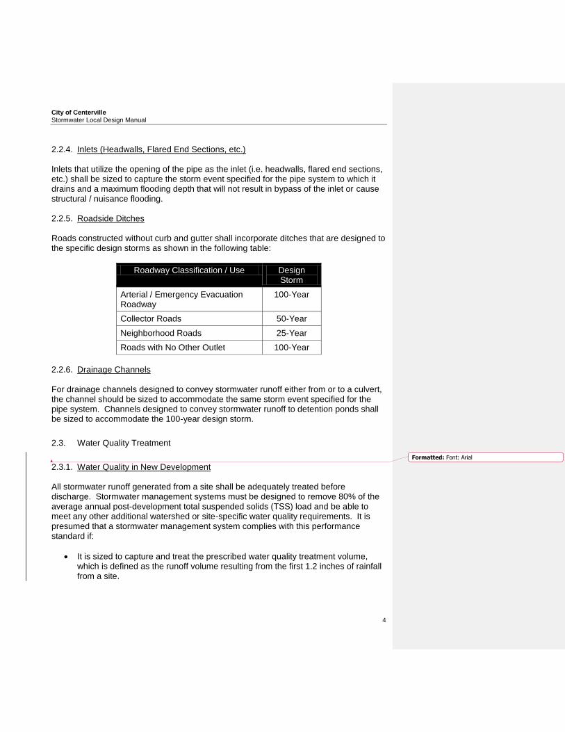
2.2.4. Inlets (Headwalls, Flared End Sections, etc.) Inlets that utilize the opening of the pipe as the inlet (i.e. headwalls, flared end sections, etc.) shall be sized to capture the storm event specified for the pipe system to which it drains and a maximum flooding depth that will not result in bypass of the inlet or cause structural / nuisance flooding. 2.2.5. Roadside Ditches Roads constructed without curb and gutter shall incorporate ditches that are designed to the specific design storms as shown in the following table:
Roadway Classification / Use Design Storm
Arterial / Emergency Evacuation Roadway
100-Year
Collector Roads 50-Year
Neighborhood Roads 25-Year
Roads with No Other Outlet 100-Year
2.2.6. Drainage Channels For drainage channels designed to convey stormwater runoff either from or to a culvert, the channel should be sized to accommodate the same storm event specified for the pipe system. Channels designed to convey stormwater runoff to detention ponds shall be sized to accommodate the 100-year design storm.
2.3. Water Quality Treatment
2.3.1. Water Quality in New Development All stormwater runoff generated from a site shall be adequately treated before discharge. Stormwater management systems must be designed to remove 80% of the average annual post-development total suspended solids (TSS) load and be able to meet any other additional watershed or site-specific water quality requirements. It is presumed that a stormwater management system complies with this performance standard if:
It is sized to capture and treat the prescribed water quality treatment volume, which is defined as the runoff volume resulting from the first 1.2 inches of rainfall from a site.
Formatted: Font: Arial

City of Centerville Stormwater Local Design Manual
5
Appropriate structural controls are selected, designed, constructed, and maintained according to the specific criteria in this manual and the GSMM.
Additional, water quality requirements may be specified for hotspot land uses and activities. 2.3.2. Water Quality in Redevelopment All stormwater runoff generated from the disturbed area of the site shall be adequately treated before discharge. Stormwater management systems must be designed to remove 80% of the average annual post-development total suspended solids (TSS) load and be able to meet any other additional watershed or site-specific water quality requirements. It is presumed that a stormwater management system complies with this performance standard if:
It is sized to capture and treat the prescribed water quality treatment volume, which is defined as the runoff volume resulting from the first 1.2 inches of rainfall from a site.
Appropriate structural controls are selected, designed, constructed, and maintained according to the specific criteria in this manual and the GSMM.
Additional, water quality requirements may be specified for hotspot land uses and activities.
2.4. Channel Protection
2.4.1. Channel Protection for New Development Projects Channel protection shall be provided for each site by providing extended detention of the 1-year storm event released over a period of 24-hours. 2.4.2. Channel Protection for Redevelopment Projects Channel protection shall be provided for the disturbed portion of each site by providing extended detention of the 1-year storm event released over a period of 24-hours.
2.5. Energy Dissipation
Energy dissipation shall be employed whenever the velocity of flows leaving a new stormwater facility exceeds the erosion velocity of the downstream area channel area or five fps whichever is less.

City of Centerville Stormwater Local Design Manual
6
3. APPROVED CONSTRUCTION MATERIALS & BMPs
3.1. Conveyance Structures
3.1.1. Pipes Under Roads and Within the Public Right-of-Way All pipes located under roadways and within the public right-of-way, and that are accepted by Centerville for long-term maintenance, shall be constructed of reinforced concrete pipe (RCP) meeting Georgia Department of Transportation Standards. Longitudinal pipes with diameters of 30-inches or smaller may utilize Corrugated Metal Pipe (CMP) or High Density Polyethylene (HDPE) Pipe if the depth of the pipe is four feet or less (as measured from the invert of the pipe to the finished grade). Minimum bedding standards for HDPE and CMP pipe shall be such that stone bedding (i.e. No. 57 stone) shall be placed to half of the pipe diameter for all depths greater than four feet and/or in accordance with manufacturer’s specifications, whichever is greater. All pipes must have a minimum of 12-inches of cover from the crown of the pipe, and in accordance with manufacturer’s specifications, provided the Owner and/or designer coordinates easement requirements with Centerville in advance. All CMP pipes shall be galvanized with a minimum of four ounces of galvanization per square foot and be 14 gauge or heavier construction. Those areas where a high ground water table exists and/or soil corrosivity and resistivity do not meet the manufacturer’s recommendation for a 50-year service life, only RCP may be utilized. Centerville may, at its discretion, require soil tests to be provided at the Owner’s expense to determine corrosivity and resistivity of the soils as well as the presence and depth of the groundwater table. All soil tests performed by the Owner must be performed in strict conformance with pipe manufacturer’s specifications. Maximum deflection of installed pipe systems shall be in accordance with manufacturer’s specifications. 3.1.2. Other Pipe Systems All other pipe systems not under roadways shall be constructed of RCP, HDPE, or CMP meeting Georgia Department of Transportation Standards and approved by Centerville. Minimum bedding standards for HDPE and CMP pipe shall be such that stone bedding (i.e. No. 57 stone) shall be placed to half of the pipe diameter for all depths greater than four feet and/or in accordance with manufacturer’s specifications, whichever is greater. All pipes must have a minimum of 12-inches of cover from the crown of the pipe, and in accordance with manufacturer’s specifications, provided the Owner and/or designer coordinates easement requirements with Centerville in advance. All CMP pipes shall be galvanized with a minimum of four ounces of galvanization per square foot, and have 3 inch by 1 inch corrugation for pipe sizes of 36 inches in diameter and larger, and be 14 gauge or heavier construction. Those areas where a high ground water table exists and/or soil corrosivity and resistivity do not meet
City of Centerville Stormwater Local Design Manual
7
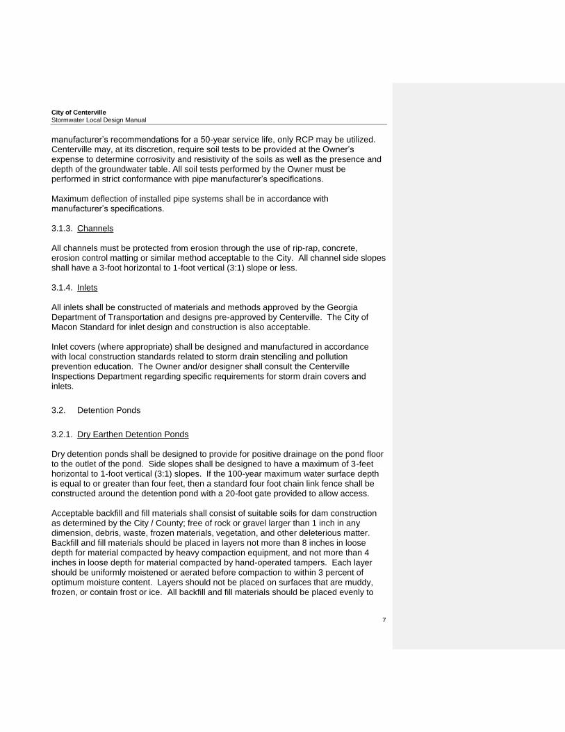
manufacturer’s recommendations for a 50-year service life, only RCP may be utilized. Centerville may, at its discretion, require soil tests to be provided at the Owner’s expense to determine corrosivity and resistivity of the soils as well as the presence and depth of the groundwater table. All soil tests performed by the Owner must be performed in strict conformance with pipe manufacturer’s specifications. Maximum deflection of installed pipe systems shall be in accordance with manufacturer’s specifications. 3.1.3. Channels All channels must be protected from erosion through the use of rip-rap, concrete, erosion control matting or similar method acceptable to the City. All channel side slopes shall have a 3-foot horizontal to 1-foot vertical (3:1) slope or less. 3.1.4. Inlets All inlets shall be constructed of materials and methods approved by the Georgia Department of Transportation and designs pre-approved by Centerville. The City of Macon Standard for inlet design and construction is also acceptable. Inlet covers (where appropriate) shall be designed and manufactured in accordance with local construction standards related to storm drain stenciling and pollution prevention education. The Owner and/or designer shall consult the Centerville Inspections Department regarding specific requirements for storm drain covers and inlets.
3.2. Detention Ponds
3.2.1. Dry Earthen Detention Ponds Dry detention ponds shall be designed to provide for positive drainage on the pond floor to the outlet of the pond. Side slopes shall be designed to have a maximum of 3-feet horizontal to 1-foot vertical (3:1) slopes. If the 100-year maximum water surface depth is equal to or greater than four feet, then a standard four foot chain link fence shall be constructed around the detention pond with a 20-foot gate provided to allow access. Acceptable backfill and fill materials shall consist of suitable soils for dam construction as determined by the City / County; free of rock or gravel larger than 1 inch in any dimension, debris, waste, frozen materials, vegetation, and other deleterious matter. Backfill and fill materials should be placed in layers not more than 8 inches in loose depth for material compacted by heavy compaction equipment, and not more than 4 inches in loose depth for material compacted by hand-operated tampers. Each layer should be uniformly moistened or aerated before compaction to within 3 percent of optimum moisture content. Layers should not be placed on surfaces that are muddy, frozen, or contain frost or ice. All backfill and fill materials should be placed evenly to
City of Centerville Stormwater Local Design Manual
8
required elevations, and uniformly along the full length of the embankment. Additionally, soils should be compacted to at least 95% maximum dry unit weight according to ASTM D 698. 3.2.2. Dry Underground Detention Ponds No underground detention pond shall be constructed on residential development projects. Underground detention ponds may be considered on non-residential development projects after the Engineer has shown that construction of an aboveground detention pond is infeasible. 3.2.3. Wet Detention Ponds Wet detention ponds may be constructed if the facilities are designed to the criteria outlined in Section 3.2.1.5 of the GSMM (Volume 2).
3.3. Water Quality Best Management Practices
3.3.1. General Application Structural Stormwater Controls The following general application structural stormwater controls shall be acceptable to meet the water quality requirements for the contributing drainage areas. For design, construction and maintenance specifications for each control, the reader is directed to Section 3.2 of the GSMM (Volume 2).
Stormwater Ponds
Stormwater Wetlands
Bioretention Areas
Sand Filters (Hotspot/Commercial Developments Only)
Enhanced Swales 3.3.2. Limited Application Structural Controls The following limited application structural stormwater controls shall be acceptable to meet the water quality requirements for the contributing drainage areas. For design, construction and maintenance specifications for each control, the reader is directed to Section 3.3 of the GSMM (Volume 2).
Filter Strip
Grass Channel
Organic Filter (Hotspot/Commercial Developments Only)
Underground Sand Filter (Hotspot/Commercial Developments Only)
Submerged Gravel Wetlands (Hotspot/Commercial Developments Only)

City of Centerville Stormwater Local Design Manual
9
3.3.3. Proprietary Structural Controls The Centerville Inspections Department may at their discretion allow proprietary structural controls. Prior to specification of such a device, the designer shall consult the Inspections Department to determine if the control will be acceptable.
3.4. Channel Protection Design
Outlets to provide for meeting channel protection criteria shall be designed to meet the standards outlined in Section 2.3.3 and Section 2.3.5 of the GSMM (Volume 2).

City of Centerville Stormwater Local Design Manual
10
4. APPROVED HYDROLOGIC & HYDRAULIC METHODS
4.1. Hydrologic Methods
4.1.1. Rational Method The rational method may be used with the approval of Centerville Inspections Department or its Agent to develop peak runoff flows for culverts with contributing drainage areas less than 10 acres in size and for detention ponds with contributing drainage areas less than 1 acre in size. All computations shall be in accordance with Section 2.1.4 of the GSMM (Volume 2). Rainfall intensities shall be derived from Table A-8 of Appendix A of the GSMM (Volume 2). As specified above, the rational method may be used to size detention facilities. If the rational method is utilized, the DeKalb Method or the Baumgardner / Morris Method (Terramodel) must be utilized to develop runoff hydrographs. Triangular rational method runoff hydrographs may not be utilized in the design of detention facilities. 4.1.2. SCS Method In most cases, the Soil Conservation Service (SCS) method must be utilized to size detention ponds with contributing drainage areas greater than 1 acre and culverts with contributing drainage areas greater than 10 acres. All computations shall be in accordance with Section 2.1.5 of the GSMM (Volume 2). Rainfall depths shall be derived from Table A-8 of Appendix A of the GSMM (Volume 2). The following table also provides the rainfall depths for use in Centerville:
Design Storm Rainfall Depth
1-Year 24-Hour 3.36”
2-Year 24-Hour 4.08”
5-Year 24-Hour 5.04”
10-Year 24-Hour
5.76”
25-Year 24-Hour
6.72”
50-Year 24-Hour
7.68”
100-Year 24-Hour
8.16”

City of Centerville Stormwater Local Design Manual
11
4.2. Hydraulic Methods
All hydraulic calculations shall be made in accordance with Chapter 4 of the GSMM (Volume 2).

City of Centerville Stormwater Local Design Manual
12
5. SPECIAL DISTRICTS The Centerville Inspections Department may establish special design criteria for select areas based on the findings of watershed assessments, hydrologic and hydraulic reports, and known flooding issues. The designer is encouraged to consult with the Inspections Department to determine if any special districts exist within Centerville. At this time, no special districts have been established.
City of Centerville Stormwater Local Design Manual
13
6. HYDROLOGIC & HYDRAULIC REPORT REQUIREMENTS All development projects must submit a hydrologic and hydraulic report outlining the impacts of the site on the stormwater system. At a minimum, this report must include the following sections:
Certification by Registered Professional
Existing Conditions Hydrologic Analysis
Post-Development Hydrologic Analysis
Stormwater Management System Design
Downstream Analysis
Erosion & Sedimentation Control Plan
Planting Plan (if applicable)
Operations & Maintenance Plan The following subsections outline the requirements for each of the elements outlined above.
6.1. Professional Certification
Each report should begin with the following statement and be signed and sealed by the professional who prepared the report and analysis:
“I, (Name of Professional), a Registered (Professional Engineer / Land Surveyor) in the State of Georgia, hereby certify that the grading and drainage plans for the project known as (Project Name), lying in Land Lot (XXX), of the (XX) District, Houston County, Georgia, have been prepared under my supervision, and, state that in my opinion, the construction of said project will not produce storm drainage conditions that will cause damage or adversely affect the surrounding properties. This (day) day of (Month), (Year).”
6.2. Existing Conditions Hydrologic Analysis
The existing conditions hydrologic analysis should provide the reader with a comprehensive evaluation of the site conditions prior to development of the project. The designer should provide the following information with this element of the report: 6.2.1. Existing Conditions Map
Topography (2-ft. or less contour interval) of existing site conditions
Perennial / intermittent streams, wetlands, lakes and other surface water features
Drainage basin delineations showing the location of each drainage sub-basin
City of Centerville Stormwater Local Design Manual
14
Drainage basin delineations for each contributing drainage basin upstream of the project site on an appropriate map (USGS Quadrangle, etc.)
Existing stormwater conveyances and structural control facilities
Direction of flow and discharge points from the site including sheet flow areas
Any area of significant depression storage 6.2.2. Existing Conditions Tables
A table listing the acreage, soil types and land cover characteristics for each sub-basin
A table listing the peak runoff rates and total runoff volumes from each sub-basin
A table listing the peak runoff rates and total runoff volumes for each drainage area upstream of the project site
A table listing the peak runoff rates and maximum water surface elevations for all detention facilities studied as part of the existing conditions analysis
6.2.3. Narratives
Written description of the existing conditions found on the site
Analysis of runoff provided by off-site areas upstream of the project site
Methodologies, assumptions, site parameters and supporting design calculations used in the analyzing the existing conditions site hydrology
6.3. Post-Development Hydrologic Analysis
The post-development hydrologic analysis should provide the reader with a comprehensive evaluation of the anticipated site conditions following development of the project. The designer should provide the following information with this element of the report: 6.3.1. Post Development Conditions Map
Topography (2-ft or less contour interval) of proposed site conditions
Perennial/intermittent streams, wetlands, lakes and other surface water features
Drainage basin delineations showing the location of each drainage sub-basin
Proposed stormwater conveyances and structural control facilities
Direction of flow and discharge points from the site including sheet flow areas
Location and boundaries of proposed natural feature protection areas 6.3.2. Post Development Conditions Tables
A table listing the acreage, soil types, impervious surface area and land cover characteristics for each sub-basin
A table listing the peak runoff rates and total runoff volumes from each sub-basin
City of Centerville Stormwater Local Design Manual
15
A table listing the peak runoff rates and total runoff volumes for each drainage area upstream of the project site
A table listing the peak discharge rates, total runoff volumes and peak elevations for all detention ponds studied
6.3.3. Narratives
Written description of the existing conditions found on the site
Stormwater calculations for water quality, channel protection and post construction detention for each sub-basin affected by the project
Documentation and calculations for any applicable site design credits that are being utilized
Methodologies, assumptions, site parameters and supporting design calculations used in the analyzing the post development conditions site hydrology
6.4. Stormwater Management System Design
The stormwater management system design should provide the reader with a comprehensive description of the proposed stormwater management system components on site. The designer should provide the following information with this element of the report: 6.4.1. Stormwater Management System Map
Location of all non-structural stormwater controls
Location of all existing stormwater controls to remain after development
Location of all proposed stormwater controls
Location of all proposed impoundment type controls (i.e. detention ponds, stormwater ponds, stormwater wetlands, etc.)
Location of all conveyance structures
All impoundment type controls should be labeled with the following information: maximum water surface elevation, depth and storage volumes for both the design storm and maximum water surface if the design storm event is exceeded (i.e. top of dam)
All inlets to conveyance structures should be labeled with the following information: maximum design water surface and maximum potential water surface
All pipes should be labeled with length, material and slope
All pipes should be profiled and labeled with length, material, slope and hydraulic grade line
Map showing all contributing drainage areas/sub-basin delineations 6.4.2. Narratives
City of Centerville Stormwater Local Design Manual
16
Narrative describing that appropriate and effective structural stormwater controls have been selected
Design calculations and elevations for all existing and proposed stormwater conveyance elements including stormwater drains, pipes culverts catch basins, channels, swales and areas of overland flow
Design calculations and elevations for all structural water quality Best Management Practices to be utilized for water quality improvement
Design calculations showing that the design meets the requirements of the water quality improvements as outlined in the ordinance and local design manual
6.5. Downstream Analysis
The downstream analysis should provide the reader with a comprehensive picture of the downstream areas and their capacity to accommodate stormwater runoff from the proposed development. 6.5.1. Maps
Drainage basin delineations showing the point at which the contributing area of the project represents 10% of the total drainage basin area as defined in Section 2.1.9.2 of the GSMM
Identify culverts, channels and other structural stormwater controls that the stormwater runoff must pass through prior to the 10% point identified previously
6.5.2. Narratives
Supporting calculations for a downstream peak flow analysis using the 10% rule necessary to show safe passage of the post-development design flows downstream
6.6. Erosion & Sedimentation Control Plan
The erosion and sedimentation control plan should be included in the report demonstrating the plan to effectively mitigate stormwater impacts during construction. The following elements should be included in this section of the report.
All elements specified in the Georgia Erosion and Sediment Control Act and local ordinances and regulations
Sequence/phasing of construction and temporary stabilization measures
Temporary structures that will be converted into permanent stormwater controls
6.7. Planting Plan

City of Centerville Stormwater Local Design Manual
17
A planting plan should be included in the report for all water quality BMPs that utilize vegetation as a pollutant removal method. Examples of these types of controls include but are not limited to stormwater wetlands, enhanced swales, etc.
City of Centerville Stormwater Local Design Manual
18
6.8. Operations & Maintenance Plan
A narrative of what maintenance tasks will be required for the stormwater controls specified for the site as well as the responsible parties. Additionally, the report will need to identify access and safety issues for the site. Maintenance issues for various BMPs and other stormwater controls can be found in the GSMM.

City of Centerville Stormwater Local Design Manual
19

City of Centerville Stormwater Local Design Manual
20
APPENDIX A
MODEL STORMWATER REPORT CHECK LIST Section 1. Report Format 1.1 Does the Hydrologic & Hydraulic Report contain the following information:
Provided Missing
Name of the Development
Name of the Developer
Location Map of the Site referencing the nearest major road
Stormwater Impact Certification
Seal of the Professional having prepared the Report
1.2 Does the Hydrologic & Hydraulic Report contain the following sections:
Provided Missing N/A
Existing Conditions Hydrologic Analysis
Post Development Hydrologic Analysis
Stormwater Management System Design
Downstream Analysis
Erosion & Sedimentation Control Plan
Planting Plan (if applicable)
Operations & Maintenance Plan
Section 2. Existing Conditions Hydrologic Analysis 2.1 This section should provide the reader with a comprehensive evaluation of the
site conditions prior to development of the project.

City of Centerville Stormwater Local Design Manual
21
2.2 Narratives – A narrative and supporting calculations of the pre-development conditions of the site as related to stormwater management should be provided to determine the current characteristics of the site.
Written description of the existing conditions found on the site
Name of the receiving waters from which runoff drains to after leaving the site
Analysis of runoff provided by off-site areas upstream of the project site
Methodologies, assumptions, site parameters and supporting design calculations used in the analyzing the existing conditions site hydrology
2.3 Existing Conditions Map – A map documenting the following elements should be
provided with the following information if applicable.
Topography (2-ft. or less contour interval) of existing site conditions
Perennial / intermittent streams, wetlands, lakes and other surface water features
Drainage basin delineations showing the location of each drainage sub-basin
Drainage basin delineations for each contributing drainage basin upstream of the project site on an appropriate map (USGS Quadrangle, etc.)
Existing stormwater conveyances and structural control facilities
Soil types including hydrologic soil groups
Direction of flow and discharge points from the site including sheet flow areas
2.4 Existing Conditions Tables – Tables documenting the following information
should be provided if applicable.
A table listing the acreage, soil types and land cover characteristics for each sub-basin
A table listing the peak runoff rates and total runoff volumes from each sub-basin
A table listing the peak runoff rates and total runoff volumes for each drainage area upstream of the project site
Section 3. Post-Development Hydrologic Analysis 3.1 The post-development hydrologic analysis should provide the reader with a
comprehensive evaluation of the anticipated site conditions following
Formatted: Font: Arial
City of Centerville Stormwater Local Design Manual
22
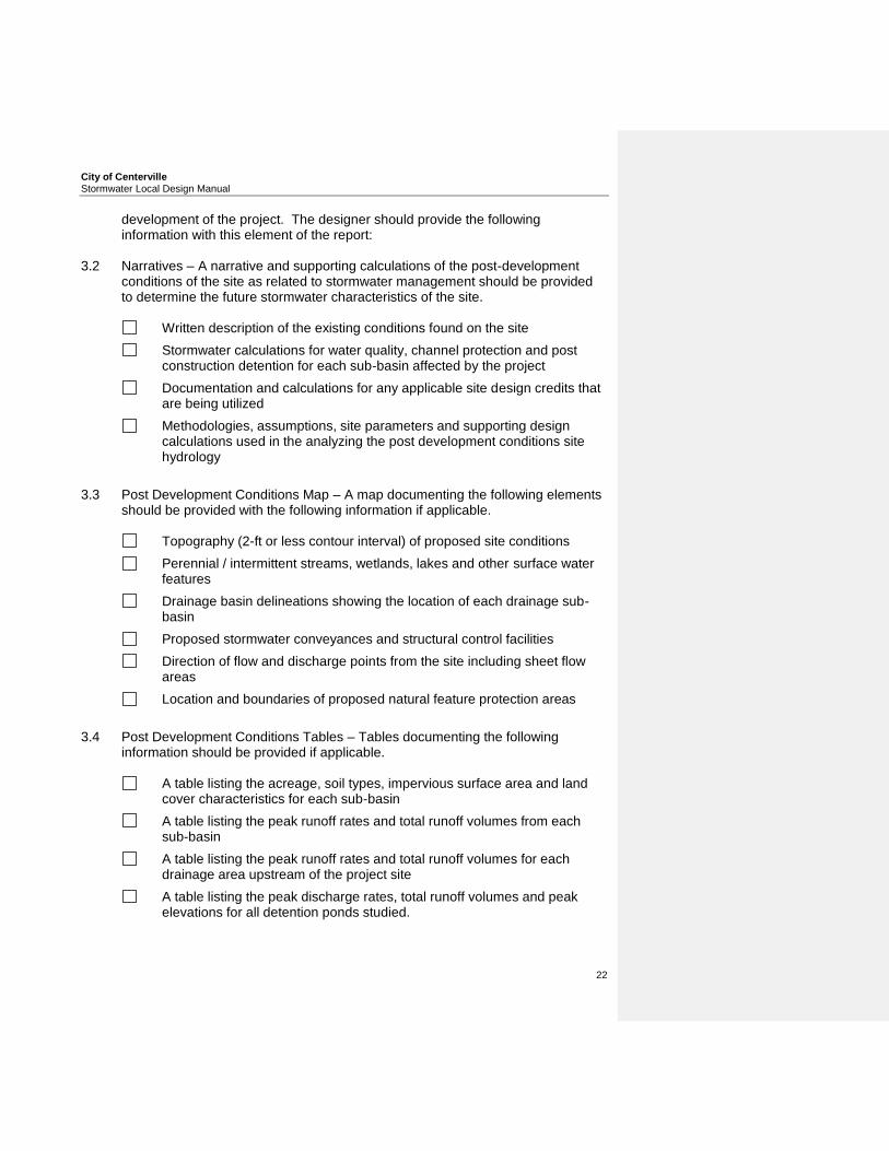
development of the project. The designer should provide the following information with this element of the report:
3.2 Narratives – A narrative and supporting calculations of the post-development
conditions of the site as related to stormwater management should be provided to determine the future stormwater characteristics of the site.
Written description of the existing conditions found on the site
Stormwater calculations for water quality, channel protection and post construction detention for each sub-basin affected by the project
Documentation and calculations for any applicable site design credits that are being utilized
Methodologies, assumptions, site parameters and supporting design calculations used in the analyzing the post development conditions site hydrology
3.3 Post Development Conditions Map – A map documenting the following elements
should be provided with the following information if applicable.
Topography (2-ft or less contour interval) of proposed site conditions
Perennial / intermittent streams, wetlands, lakes and other surface water features
Drainage basin delineations showing the location of each drainage sub-basin
Proposed stormwater conveyances and structural control facilities
Direction of flow and discharge points from the site including sheet flow areas
Location and boundaries of proposed natural feature protection areas
3.4 Post Development Conditions Tables – Tables documenting the following
information should be provided if applicable.
A table listing the acreage, soil types, impervious surface area and land cover characteristics for each sub-basin
A table listing the peak runoff rates and total runoff volumes from each sub-basin
A table listing the peak runoff rates and total runoff volumes for each drainage area upstream of the project site
A table listing the peak discharge rates, total runoff volumes and peak elevations for all detention ponds studied.

City of Centerville Stormwater Local Design Manual
23
Section 4. Stormwater Management System 4.1 The stormwater management system section should provide the reader with a
comprehensive description of the proposed stormwater management system components on site. The designer should provide the following information with this element of the report:
4.2 Narratives – A narrative and supporting calculations describing the on-site
stormwater management controls to be utilized. This narrative should include appropriate narratives / tables demonstrating compliance with the various stormwater management requirements outlined in the post-development article of the stormwater ordinance and local design manual.
Narrative describing that appropriate and effective structural stormwater
controls have been selected
Design calculations and elevations for all existing and proposed stormwater conveyance elements including stormwater drains, pipes culverts catch basins, channels, swales and areas of overland flow
4.3 Stormwater Management System Map(s) – A map(s) illustrating the location,
type and specifications of all stormwater management components to provide stormwater management for the proposed site.
Location of all non-structural stormwater controls
Location of all existing stormwater controls to remain after development
Location of all proposed stormwater controls
Location of all proposed impoundment type controls (i.e. detention ponds, stormwater ponds, stormwater wetlands, etc.)
Location of all conveyance structures
All impoundment type controls should be labeled with the following information: maximum water surface elevation, depth and storage volumes for both the design storm and maximum water surface if the design storm event is exceeded (i.e. top of dam)
All inlets to conveyance structures should be labeled with the following information: maximum design water surface and maximum potential water surface
All pipes should be labeled with length, material and slope
All pipes should be profiled and labeled with length, material, slope and hydraulic grade line
City of Centerville Stormwater Local Design Manual
24
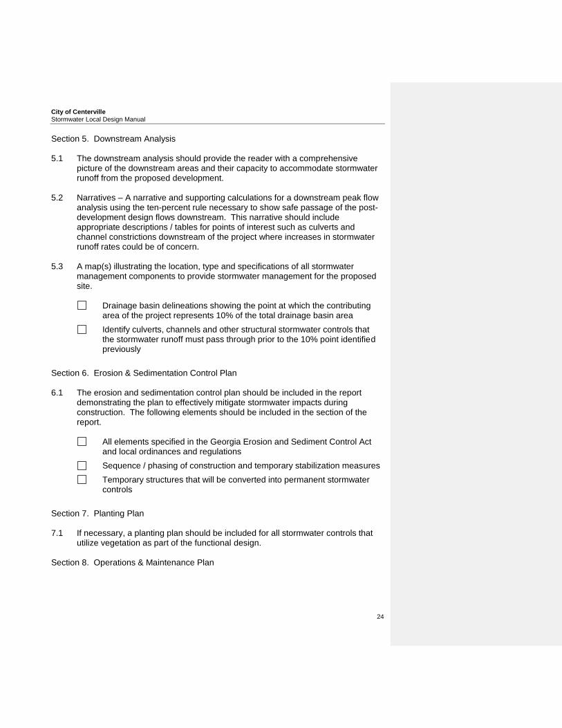
Section 5. Downstream Analysis 5.1 The downstream analysis should provide the reader with a comprehensive
picture of the downstream areas and their capacity to accommodate stormwater runoff from the proposed development.
5.2 Narratives – A narrative and supporting calculations for a downstream peak flow
analysis using the ten-percent rule necessary to show safe passage of the post-development design flows downstream. This narrative should include appropriate descriptions / tables for points of interest such as culverts and channel constrictions downstream of the project where increases in stormwater runoff rates could be of concern.
5.3 A map(s) illustrating the location, type and specifications of all stormwater
management components to provide stormwater management for the proposed site.
Drainage basin delineations showing the point at which the contributing
area of the project represents 10% of the total drainage basin area
Identify culverts, channels and other structural stormwater controls that the stormwater runoff must pass through prior to the 10% point identified previously
Section 6. Erosion & Sedimentation Control Plan 6.1 The erosion and sedimentation control plan should be included in the report
demonstrating the plan to effectively mitigate stormwater impacts during construction. The following elements should be included in the section of the report.
All elements specified in the Georgia Erosion and Sediment Control Act
and local ordinances and regulations
Sequence / phasing of construction and temporary stabilization measures
Temporary structures that will be converted into permanent stormwater controls
Section 7. Planting Plan 7.1 If necessary, a planting plan should be included for all stormwater controls that
utilize vegetation as part of the functional design. Section 8. Operations & Maintenance Plan

City of Centerville Stormwater Local Design Manual
25
8.1 A narrative of what maintenance tasks will be required for the stormwater controls specified for the site as well as the responsible parties. Additionally, the report will need to identify access and safety issues for the site.