Model RK1 - Javascript discriminationclarion.com/us/en/MungoBlobs/344/499/RK1_INSTALL,1.pdf4...
46
NOTE: This product is intended for installation by a professional installer only! Any attempt to install this product by any person other than a trained professional may result in severe damage to a vehicle’s electrical system and components. Model RK1 installation guide
Transcript of Model RK1 - Javascript discriminationclarion.com/us/en/MungoBlobs/344/499/RK1_INSTALL,1.pdf4...

NOTE: This product is intended for installation by a professional installer only!Any attempt to install this product by any person other than a trained professionalmay result in severe damage to a vehicle’s electrical system and components.
Model RK1installation guide

2
table of contents
table of contents . . . . . . . . . . . . . . . . . . . . . . .2warning! safety first . . . . . . . . . . . . . . . . . . . .3installation points to remember . . . . . . . . . .4
before beginning the installation . . . . . . . . .4after the installation . . . . . . . . . . . . . . . . . . .4
deciding on component locations . . . . . . . . .4control module . . . . . . . . . . . . . . . . . . . . . . .4override switch . . . . . . . . . . . . . . . . . . . . . . .5status LED . . . . . . . . . . . . . . . . . . . . . . . . . . .6
finding the wires you need . . . . . . . . . . . . . .6obtaining constant 12V . . . . . . . . . . . . . . . .6finding the 12V switched ignition wire . . . . .7finding the starter wire . . . . . . . . . . . . . . . . .8finding a (+) brake light wire . . . . . . . . . . . .8finding the accessory/heater wire . . . . . . . . .9finding the RPM input wire . . . . . . . . . . . . . .9finding the wait-to-start bulb wire for diesels 9
wiring diagrams . . . . . . . . . . . . . . . . . . . . . .10primary harness (H1) wiring diagram . . . . .10remote start ribbon harness wiring diagram 11heavy gauge relay satellite wiring diagram .11auxiliary harness (H2) wiring diagram . . . . .11remote start harness (H3) wiring diagram . .12door lock harness (H4) wiring diagram . . . .12remote start auxiliary harness wiring diagram .12
primary harness (H1) wire connection guide13relay satellite connecting to key switch wireconnection guide . . . . . . . . . . . . . . . . . . . . .164-pin satellite harness wire connection guide17auxiliary harness (H2) wire connection guide .18remote start harness (H3) wire connectionguide . . . . . . . . . . . . . . . . . . . . . . . . . . . . . . .20neutral safety switch interface . . . . . . . . . .21
testing the neutral safety switch . . . . . . . . .22
1995 and newer vehicle anti-theft systems(immobilizers) . . . . . . . . . . . . . . . . . . . . . . . .24
passlock I and passlock II (PL-1 and PL-2) . .24passkey III (PK-3), transponder-based systems .24
bypassing GM vehicle anti-theft systems(VATS) . . . . . . . . . . . . . . . . . . . . . . . . . . . . . . .25plug-in LED and override switch . . . . . . . . .26programmer interface, 3-pin port . . . . . . . .26programming jumpers . . . . . . . . . . . . . . . . .27
light flash (+)/(-) . . . . . . . . . . . . . . . . . . . . .27tach threshold on/off . . . . . . . . . . . . . . . . .27
remote coding . . . . . . . . . . . . . . . . . . . . . . . .28remote configurations . . . . . . . . . . . . . . . . .30
button configuration . . . . . . . . . . . . . . . . . .30module programming . . . . . . . . . . . . . . . . .30feature menus . . . . . . . . . . . . . . . . . . . . . . . .32
menu #2 . . . . . . . . . . . . . . . . . . . . . . . . . . .33feature descriptions . . . . . . . . . . . . . . . . . . .34
menu #1 . . . . . . . . . . . . . . . . . . . . . . . . . . .34menu #2 . . . . . . . . . . . . . . . . . . . . . . . . . . .35
tach learning . . . . . . . . . . . . . . . . . . . . . . . . .37remote start diagnostics . . . . . . . . . . . . . . . .38power-up . . . . . . . . . . . . . . . . . . . . . . . . . . . .39timer mode . . . . . . . . . . . . . . . . . . . . . . . . . .39override mode . . . . . . . . . . . . . . . . . . . . . . . .40safety check . . . . . . . . . . . . . . . . . . . . . . . . . .40troubleshooting . . . . . . . . . . . . . . . . . . . . . .41wiring quick reference guide . . . . . . . . . . . .43relay satellite wiring quick reference guide 44

3
warning! safety firstIIMMPPOORRTTAANNTT!! This product is designed for fuel-injected, automatic transmission vehicles only. Installing it in a stan-dard transmission vehicle is dangerous and is contrary to its intended use.
The following safety warnings must be observed at all times:
● Due to the complexity of this system, installation of this product must only be performed by anauthorized dealer.
● When properly installed, this system can start the vehicle via a command signal from the remotecontrol. Therefore, never operate the system in an area that does not have adequate ventilation.The following precautions are the sole responsibility of the user; however, authorized dealersshould make the following recommendations to all users of this system:
1. Never operate the system in an enclosed or partially enclosed area without ventilation (suchas a garage).
2. When parking in an enclosed or partially enclosed area or when having the vehicle serviced,the remote engine start system must be disabled using the installed toggle switch.
3. It is the user's sole responsibility to properly handle and keep out of reach from children all remotecontrols to assure that the system does not unintentionally remote engine start the vehicle.
4. THE USER MUST INSTALL A CARBON MONOXIDE DETECTOR IN OR ABOUT THE LIVINGAREA ADJACENT TO THE VEHICLE. ALL DOORS LEADING FROM ADJACENT LIVING AREASTO THE ENCLOSED OR PARTIALLY ENCLOSED VEHICLE STORAGE AREA MUST AT ALL TIMESREMAIN CLOSED.

4
installation points to remember
before beginning the installation
IIMMPPOORRTTAANNTT!! This product is designed for fuel-injected, automatic transmission vehicles only. Installing it in a stan-dard transmission vehicle is dangerous and is contrary to its intended use.
● Please read this entire installation guide before beginning the installation. The installation of thisremote engine start system requires interfacing with many of the vehicle’s systems. Many newvehicles use low-voltage or multiplexed systems that can be damaged by low resistance testingdevices, such as test lights and logic probes (computer safe test lights). Test all circuits with a highquality digital multi-meter before making connections.
● Do not disconnect the battery if the vehicle has an anti-theft-coded radio. If equipped with an airbag, avoid disconnecting the battery if possible. Many airbag systems will display a diagnosticcode through their warning lights after they lose power. Disconnecting the battery requires thiscode to be erased, which can require a trip to the dealer.
● Remove the domelight fuse. This prevents accidentally draining the battery.● Roll down a window to avoid being locked out of the car.
after the installation● Test all functions. The "Using Your System" section of the Owner's Guide is very helpful when testing.● Complete the vehicle Safety Check outlined in this manual prior to the vehicle reassembly.● Reinstall domelight fuse.
deciding on component locations
control moduleThings to remember when positioning the control module:
● Never place the control module in the engine compartment!● The first thing a thief will do when hot-wiring a vehicle is to remove the driver's side under-dash
panel to access the starter and ignition wires. You should therefore avoid placing the controlmodule just behind the driver’s side dash to prevent it from being easily disconnected during atheft attempt.
● When locating the control module, try to find a secure location that will not require you to extendthe harness wires (they are 1.5 meters long).

5
● Keep the control module away from the heater core (or any other heat sources) and any obvious leaks.● The higher the control module is in the vehicle, the better the remote range will be. Some good
control module locations: Above the glove box, inside the center console, above the under-dashfuse box, or above the radio.
override switchEnsure that the location you pick for this switch has sufficient clearance to the rear. The switch shouldbe well hidden. It should be placed so that passengers or stored items (such as items placed in aglove box or center console) cannot accidentally bump it. The switch fits in a 9/32-inch hole.
IIMMPPOORRTTAANNTT!! When the vehicle is delivered, please show the user where the Override switch is located andhow to disarm the system using the switch.

6
status LEDThings to remember when installing the status LED:
● It should be visible from both sides and the rear of the vehicle, if possible.● It needs at least 1/2-inch clearance to the rear.● It is recommended to use a small removable panel, such as a switch blank or a dash bezel.
Remove it before drilling your 9/32-inch hole.● Use quick-disconnects near the LED wires if the panel is removable. This lets mechanics or other
installers remove the panel without having to cut the wires.
finding the wires you needNow that you have determined where each component will be located, your next step is to find thewires in the vehicle that the security system will be connected to.
IIMMPPOORRTTAANNTT!! Do not use a 12V test light to locate these wires! All testing described in this manual assumes theuse of a digital multimeter.
obtaining constant 12VWe recommend two possible sources for 12V constant: The (+) terminal of the battery, or the con-stant 12V supply to the ignition switch. Always install a fuse within 12 inches of this connection. Ifthe fuse will also be powering other circuits, such as door locks, a power window module, or a head-light control system, fuse accordingly. Some vehicles have a low current (10 Vdc) source at the col-umn. For these vehicles it is recommended to connect to the (+) terminal of the battery.
IIMMPPOORRTTAANNTT!! Do not remove the fuse holder on the red wire. It ensures that the control module has its own fuse,of the proper value, regardless of how many accessories are added to the main power feed.

7
finding the 12V switched ignition wireThe ignition wire is powered when the key is in the run and start position. This is because the igni-tion wire powers the ignition system (spark plugs, coil) as well as the fuel delivery system (fuel pump,fuel injection computer). Accessory wires lose power when the key is in the start position to makemore current available to the starter motor.
How to find (+)12V ignition with your multimeter:
1. Set to DCV or DC voltage (12V or 20V is fine).
2. Attach the (-) probe of the meter to chassis ground.
3. Probe the wire you suspect of being the ignition wire. The steer-ing column harness or ignition switch harness is an excellentplace to find this wire.
4. Turn the ignition key switch to the run position. If your meter reads (+)12V, go to the next step.If it does not read (+)12V, probe another wire.
5. Now turn the key to the start position. The meter display should stay steady, not dropping bymore than a few tenths of a volt. If it drops close to or all the way to zero, go back to Step 3. Ifit stays steady at (+)12V, you have found an ignition wire.

8
finding the starter wireThe starter wire provides 12V directly to the starter or to a relay controlling starter. In some vehicles,it is necessary to power a cold start circuit. A cold start circuit will test exactly like a starter circuit,but it does not control the starter. Instead, the cold start circuit is used to prime the fuel injection sys-tem for starting when the vehicle is cold.
How to find the starter wire with your multimeter:
1. Set to DCV or DC voltage (12V or 20V is fine).
2. Attach the (-) probe of the meter to chassis ground.
3. Probe the wire you suspect of being the starter wire. The steer-ing column is an excellent place to find this wire. Remember youdo not need to interrupt the starter at the same point you test it.Hiding your optional starter kill relay and connections is always recommended.
4. Turn the ignition key switch to the start position. Make sure the car is not in gear! If your meterreads (+)12V, go to the next step. If it doesn’t, probe another wire.
5. Cut the wire you suspect of being the starter wire.
6. Attempt to start the car. If the starter engages, reconnect it and go back to Step 3. If the starterdoes not turn over, you have the right wire.
finding a (+) brake light wireMost vehicles use a (+) brake light circuit. The (+) brake light wire is often found near the brakepedal. The same wire can often be accessed in the kick panel or running board.
How to find a (+) brake light wire with your multimeter:
1. Set to DCV or DC voltage (12V or 20V is fine).
2. Attach the (-) probe of the meter to chassis ground.
3. Probe the wire you suspect of being the brake light wire.
4. Press the brake pedal. If your meter shows (+)12V, release the brake pedal and make sure it goesback to zero.
5. If it does return to zero, this is the correct brake wire.

9
finding the accessory/heater wireAn accessory/heater wire will show +12V when the key is in the accessory and run positions. It willnot show +12V during the cranking cycle. There will often be more than one accessory wire in theignition harness. The correct accessory wire will power the vehicle's climate control system. Somevehicles may have separate wires for the blower motor and the air conditioning compressor. In suchcases, it will be necessary to add a relay to power the second accessory wire.
finding the RPM input wireTo test for a tachometer wire, a multimeter capable of testing AC voltage must be used. The tachome-ter wire will show between 1V and 6V AC. In multi-coil ignition systems, the system can learn indi-vidual coil wires. Individual coil wires in a multi-coil ignition system will register lower amounts ofAC voltage. Also, if necessary, the system can use a non-common fuel injector control wire forengine speed sensing. Common locations for a tachometer wire are the ignition coil itself, the backof the gauges (if a tachometer is present), engine computers, and automatic transmission computers.
IIMMPPOORRTTAANNTT!! Do not test tachometer wires with a test light or logic probe. The vehicle will be damaged.
How to find a tachometer wire with your multimeter:
1. Set to ACV or AC voltage (12V or 20V is fine).
2. Attach the (-) probe of the meter to chassis ground.
3. Start and run the vehicle.
4. Probe the wire you suspect of being the tachometer wire with the red probe of the meter.
5. If this is the correct wire the meter will fluctuate with the rpm of the motor and read between 1Vand 6V.
finding the wait-to-start bulb wire for dieselsIn diesel vehicles it is necessary to interface with the wire that turns on the WAIT TO START light inthe dashboard. This wire illuminates the bulb until the vehicle’s glow plugs are properly heated.When the light goes out the vehicle can be started. This wire is always available at the connectorleading to the bulb in the dashboard. It can also be found at the Engine Control Module (ECM) inmany vehicles. Some vehicles employ a data line (rather than analog) from the ECM which mayrequire an additional timer.

10
To test and determine the polarity of this wire:
1. Set your multimeter to DCV or DC voltage (12 or 20V is fine).
2. Attach the (+) probe of the meter to (+)12V.
3. Probe the wire that you suspect leads to the bulb with the (-) probe of the meter.
4. Turn the ignition switch to the ON position.
5. If the meter indicates 12 volts until the light goes out you have isolated the correct wire and thewire's polarity is negative (ground while the bulb is on).
6. If the meter reads zero volts until the light goes out and then reads 12 volts, you have isolatedthe correct wire and the wire's polarity is positive.
wiring diagrams
primary harness (H1) wiring diagramThe primary harness supplied with this unit is the standard 12-pin harness. Three wires in the har-ness are not used. The upgrade from this unit to a security system would simply require unpluggingand exchanging control units and connecting the necessary wires to the vehicle. The functions of allthe wires that are used in the primary harness are outlined in the following wiring diagram and thewire connections are described in the wire connection guides.
______
______
______
______
______
______
______
______
______
______
______
______ RED/WHITE (-)200 mA CHANNEL 2 VALIDITY OUTPUT
RED (+) CONSTANT POWER INPUT
BROWN (-) HORN H0NK OUTPUT
NO FUNCTION
BLACK (-) CHASSIS GROUND INPUT
VIOLET NO FUNCTION
BLUE (-) SECOND UNLOCK OUTPUT
GREEN NO FUNCTION
BLACK/WHITE (-)200 mA DOMELIGHT SUPERVISION OUTPUT
WHITE/BLUE (-) REMOTE START ACTIVATION INPUT
WHITE (+)/(-) SELECTABLE LIGHT FLASH OUTPUT
ORANGE (-) 500 mA ARMED OUTPUTH1/1
H1/2
H1/3
H1/4
H1/5
H1/6
H1/7
H1/8
H1/9
H1/10
H1/11
H1/12

11
remote start ribbon harness wiring diagram______
______
______
______
______
______
______
heavy gauge relay satellite wiring diagram______
______
______
______
______
______
______
______
auxiliary harness (H2) wiring diagram______
______
______
______ LIGHT GREEN/BLACK (-) FACTORY DISARM
GRAY/BLACK (-) WAIT-TO-START INPUT
GREEN/WHITE (-) FACTORY REARM OUTPUT
VIOLET/BLACK (-) CHANNEL 4 OUTPUTH2/1
H2/2
H2/3
H2/4
PINK/WHITE (+) OUTPUT TO SECOND IGNITION/ACCESSORY CIRCUIT
RED/WHITE HIGH CURRENT 12V INPUT
PINK (+) OUTPUT TO IGNITION CIRCUIT
RED (+) (30A) HIGH CURRENT 12V INPUT
ORANGE (+) OUTPUT TO ACCESSORY CIRCUIT
RED (+) (30A) HIGH CURRENT 12V INPUT
GREEN STARTER INPUT FROM IGNITION (KEY SIDE)
PURPLE (+) STARTER OUTPUT TO STARTER (STARTER SIDE)1
2
3
4
5
6
7
8
BLUE (-) 200 mA STATUS OUTPUT
ORANGE/BLACK (-) ANTI-GRIND OUTPUT/GROUND WHEN ARMED OUTPUT
PURPLE (-) 200 mA STARTER RELAY TURN-ON
ORANGE (-) 200 mA ACCESSORY RELAY TURN-ON
PINK (-) 200 mA IGNITION RELAY TURN-ON
YELLOW (+) IGNITION INPUT TO REMOTE START
PINK/WHITE (-) 200 mA PROGRAMMABLE ACC/IGN OUTPUT1
2
3
4
5
6
7

12
remote start harness (H3) wiring diagram______
______
______
______
______
door lock harness (H4) wiring diagram______
______
______
remote start auxiliary harness wiring diagram______
______
______
______ PURPLE (-) 200 mA STARTER RELAY OUTPUT
PINK (-) 200 mA IGNITION RELAY OUTPUT
ORANGE (-) 200 mA ACCESSORY RELAY OUTPUT
BLUE (-) 200 mA STATUS OUTPUT1
2
3
4
BLUE (+) LOCK (-) UNLOCK
NO FUNCTION
GREEN (-) LOCK (+) UNLOCKH4/1
H4/2
H4/3
BLACK/WHITE (-) NEUTRAL SAFETY SWITCH INPUT
VIOLET/WHITE TACHOMETER INPUT WIRE
BROWN (+) BRAKE SWITCH SHUTDOWN WIRE
GRAY (-) HOOD PINSWITCH SHUTDOWN WIRE
BLUE/WHITE (-) 200 mA 2ND STATUS/REAR DEFOGGER - LATCHED/PULSEDH3/1
H3/2
H3/3
H3/4
H3/5

13
primary harness (H1) wire connection guideH1/1 ORANGE (-) ground-when-armed output
This wire supplies a (-)500 mA ground as long as the system is armed. This output ceases as soonas the system is disarmed. The orange wire may be wired to an optional accessory.
H1/2 WHITE (+/-) selectable light flash output
As shipped, this wire should be connected to the (+) parking light wire. If the light flash polarityjumper is moved to the opposite position (see Internal Programming Jumpers section), this wire sup-plies a (-)200 mA output. This is available for driving (-) light control wires in Toyota, Lexus, BMW,some Mitsubishi, some Mazda, and various other models.
(+) Positive Light Flash Output
(-) Light Flash Output
NNOOTTEE:: For parking light circuits that draw 10 amps or more, the internal jumper must be switched to a (-) lightflash output. (See the Internal Programming Jumper section of this guide.) A standard automotive SPDT relay mustbe used on the H1/2 light flash output harness wire.

14
H1/3 WHITE/BLUE (-) remote start activation input
This input comes from the factory set to 2 activation pulses. This means that it is necessary to have2 consecutive ground pulses on the white/blue wire for the remote start to activate or to deactivate.The same holds true for the remote control activation when set to a two pulse setting it is necessaryto press the button twice for the remote start to activate or deactivate.
NNOOTTEE:: When the activation pulse count can be programmed to 1, 2, or 3 pulses when changed it will affectboth activation inputs; the White/Blue wire and the remote control activation.
H1/4 BLACK /WHITE (-) 200 mA domelight supervision output
Connect this wire to the optional domelight supervision relay as shown below:
IIMMPPOORRTTAANNTT!! This output is only intended to drive a relay. It cannot be connected directly to the domelight cir-cuit because the output cannot support the current draw of one or more light bulbs.
H1/6 BLUE second unlock
This output is used for progressive door unlock. A progressive unlock system unlocks the driver'sdoor when the unlock (disarm) button is pressed and unlocks the passenger doors if the unlock(disarm) button is pressed again within 15 seconds after unlocking the driver's door. The BLUEwire outputs a low current (-) pulse on the second press of the unlock button of the remote. Thisnegative unlock output is used to unlock the passenger doors.
NNOOTTEE:: The second unlock output feature is not available if the double pulse unlock feature is turned on.

15
H1/8 BLACK (-) chassis ground connection
Remove any paint and connect this wire to bare metal, preferably with a factory bolt rather than yourown screw. (Screws tend to either strip or loosen with time.) We recommend grounding all your com-ponents, including the siren, to the same point in the vehicle. This connection should NOT be madeto an underdash panel or bracket.
H1/10 BROWN (-) horn honk output
This wire supplies a (-) 200 mA output that can be used to honk the vehicle horn. It outputs a singlepulse when locking the doors with the remote, and two pulses when unlocking with the remote. Thiswire will also output pulses for 30 seconds when the panic mode is activated. If the vehicle has a (+)horn circuit, an optional relay can be used to interface with the system, as shown below.

16
H1/11 RED (+)12V constant power input
Before connecting this wire, remove the supplied fuse. Connect to the battery positive terminal or theconstant 12V supply to the ignition switch.
NNOOTTEE:: Always use a fuse within 12 inches of the point you obtain (+)12V. Do not use the 10A fuse in the har-ness for this purpose. This fuse is intended to protect the module.
H1/12 RED/WHITE Channel 2, (-) 200 mA output
When the system receives the code controlling Channel 2, for longer than 1.5 seconds, theRED/WHITE wire will supply an output as long as the transmission continues. This is often used tooperate a trunk/hatch release or other relay-driven function.
IIMMPPOORRTTAANNTT!! Never use this wire to drive anything except a relay or low-current input! The transistorized outputcan only supply 200 mA of current. Connecting directly to a solenoid, motor, or other high-current device willcause it to fail.
relay satellite connecting to key switchwire connection guideAll except the red heavy gauge wires leading from the relay satellite are used to energize high cur-rent circuits in the vehicle. It is crucial that these connections are made correctly so that they arecapable of handling the current demands. For this reason, scotch locks, T-taps and other such con-nectors should not be used.
PURPLE (+) starter output
After cutting the starter wire connect the PURPLE wire to the end going to the starter motor.
GREEN starter kill
After cutting the starter wire connect the GREEN wire to the end going to the key side of the ignition switch.

17
RED (2) (+)12V input for relays
Remove the two 30 amp fuses prior to connecting these wires and do not replace them until the satel-lite has been plugged into the control module. These wires are the source of current for all the cir-cuits the relay satellite will energize. They must be connected to a high current source. Since the fac-tory supplies (+) 12V to the key switch that is used to operate the motor, it is recommended that thesewires be connected there.
NNOOTTEE:: If the factory supplies two separate (+) 12V feeds to the ignition switch, connect one RED wire of thesatellite to each feed at the switch.
Some vehicles have a low current (10 Vdc) source at the column. For these vehicles it is recom-mended to connect to the (+) terminal of the battery.
ORANGE (+) accessory output
Connect this wire to the accessory wire in the vehicle that powers the climate control system.
PINK (+) ignition output
Connect this wire to the primary ignition wire in the vehicle.
PINK/WHITE (+) output to second ignition/accessory circuit
Connect this wire to the second ignition or accessory wire in the vehicle (selectable menu feature 2-9).
RED/WHITE 12 V input
If additional current capacity is needed cut this wire, add a fuse adequate for the circuit to be sup-plied, and connect to an additional 12V source.
4-pin satellite harness wire connection guideBLUE (-) status output
For use when immobilizer bypass is required.
ORANGE (-) 200mA 2nd accessory output
To drive relay for 2nd or 3rd accessory.
VIOLET (-) 200mA starter output
To drive relay for 2nd starter.
PINK (-) 200mA 3rd ignition output
To drive relay for 2nd or 3rd ignition.

18
auxiliary harness (H2) wire connection guideH2/1 VIOLET/BLACK (-) channel 4 output
This wire provides 200 mA programmable output. (See Feature Descriptions section of this guide.)
H2/2 GREEN/WHITE factory rearm output
This wire sends a negative pulse every time the remote start shuts down or the doors are locked. Thiscan be used to pulse the arm wire of the vehicle's factory anti-theft device. Use a relay to send a (-) or (+) pulse to the arm wire.
H2/3 GRAY/BLACK (-) diesel wait-to-start bulb input
Connect this wire to the wire in the vehicle that sends the signal to turn on the WAIT-TO-START bulbin the dashboard. In most diesels the wire is negative (ground turns on the bulb) and theGRAY/BLACK can be directly connected to the wire in the vehicle. If the vehicle uses a positive wire(12V to turn on the bulb) a relay must be used to change the polarity. (See Finding the Wait-To-StartBulb Wire For Diesels section of this guide.) Here are some common colors of this wire:
● Chevrolet and GMC trucks: Light Blue or Dark Blue● Ford Trucks: Black/Pink● Dodge Ram Trucks: Orange/Black or Black/Orange
NNOOTTEE!! A 1-amp diode must be installed in line on the factory wire between the wait-to-start indicator and theECM. (See the following diagram for details.)
19
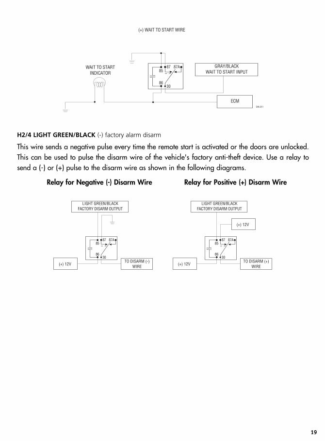
H2/4 LIGHT GREEN/BLACK (-) factory alarm disarm
This wire sends a negative pulse every time the remote start is activated or the doors are unlocked.This can be used to pulse the disarm wire of the vehicle's factory anti-theft device. Use a relay tosend a (-) or (+) pulse to the disarm wire as shown in the following diagrams.
Relay for Negative (-) Disarm Wire Relay for Positive (+) Disarm Wire

20
remote start harness (H3) wireconnection guideH3/1 BLUE/WHITE status/defogger output
This wire supplies a 200mA output as soon as the module begins the remote start process. The H3/1BLUE/WHITE wire can also be used to activate the defogger trigger (latched/pulsed) 10-secondsafter the remote start engages. (See the Feature Descriptions section in this guide for details aboutprogramming this output.)
H3/3 GRAY (-) hood pinswitch input
This wire MUST be connected to hood pinswitch. This input will disable or shut down the remote startwhen the hood is opened.
H3/4 BROWN (+) brake switch input
This wire MUST be connected to the vehicle's brake light wire. This is the wire that shows (+) 12Vwhen the brake pedal is pressed. The remote start will be disabled or shut down any time the brakepedal is pressed.
H3/5 VIOLET/WHITE tachometer input
This input provides the module with information about the engine's revolutions per minute (RPMs). Itcan be connected to the negative side of the coil in vehicles with conventional coils. In multi-coil andhigh energy ignition systems locating a proper signal may be more difficult. (See Installation Pointsto Remember section of this guide for finding the tachometer wire.) Once connected, you must teachthe system the tach signal. (See Tach Learning section of this guide.)
H3/6 BLACK/WHITE neutral safety switch input
Connect this wire to the toggle (override) switch as shown in Figure A. Connect the other wire fromthe toggle switch to the park/neutral switch in the vehicle. This wire will test with ground with thegear selector either in PARK or NEUTRAL. This will prevent the vehicle from accidentally being start-ed while in a drive gear. This input MUST rest at ground in order for the remote start system to oper-ate. Connected properly the vehicle will only start while in PARK or NEUTRAL.
In some vehicles, the park/neutral position switch activates a factory starter lock out that will notallow the starter to operate in a drive gear. In these vehicles, connect this wire to the toggle switchas shown in Figure B. Connect the other wire from the toggle switch to chassis ground.

21
Figure A Figure B
IIMMPPOORRTTAANNTT!! Always perform the Vehicle Safety Check section of this guide to verify that the vehicle cannot bestarted in ANY drive gear and that the override switch is functioning properly.
neutral safety switch interfaceSome vehicles combine the column shift mechanism and the mechanical neutral safety switch intoone mechanical part. In these vehicles, it is impossible to interface the remote start system before theneutral safety switch. With this type of vehicle, if the vehicle is left in a drive gear and the remotestart system is activated, the vehicle will move and may cause damage to persons or property.
According to available information, vehicles known to be manufactured this way are most GeneralMotors trucks, sport utility vehicles and column shifting passenger vehicles. Available information alsoindicates that pre-1996 Dodge Dakota pickups with 2.5 liter motors are also manufactured this way.
GM vehicles that have the neutral safety switch built into the column shifter can usually be identified bya purple starter wire. Typically, vehicles that use an outboard mechanical switch use a yellow wire fromthe ignition switch to the mechanical switch and a purple wire from the mechanical switch to the starteritself. Remember, this is only a rule of thumb and is not intended as a substitute for proper testing.
We suggest the following procedure to test for vehicles manufactured in this way.
NNOOTTEE:: You must complete the remote start system installation before doing the following test. Ensure that theremote start system is functioning normally. This includes connecting to the brake as a shut-down.

22
testing the neutral safety switch1. Make sure there is adequate clearance to the front and rear of the vehicle because it may move slightly.
2. Make sure the hood is closed and there are no remote start shut-downs active.
3. Set the emergency brake.
4. Turn the key to the "run" position, this will release the shifter.
5. Place the car in drive (D).
6. Place your foot directly over the brake pedal, but do not depress it. Be ready to step on the brakeif the starter engages.
7. Activate the remote start system.
8. If the starter engages, immediately depress the brake to shut the remote start system down. If thestarter does not engage, no additional safety system is required.
If the starter engages and the vehicle is a General Motors product or Dodge Dakota pickup, refer tothe following text and diagrams for an alternative shut-down method which will prevent the starterfrom engaging. If the vehicle is not a General Motors product or a Dodge Dakota pickup, please callTechnical Support for an alternative shut-down method. Do not return the vehicle to the customer untilthis feature is properly installed!
Every vehicle built this way requires that the shifter be placed in park to remove the keys from theignition. As a result, it is possible to use the key-in-ignition sense switch to prevent remote starting ifthe keys are in the ignition. The diagrams in this section illustrate how to accomplish this.
Diagram A applies to all General Motors vehicles at the time of publication of this guide. DiagramB applies to all pre-1996 Dodge Dakota pickup trucks with 2.5 liter motors. This solution has oneside effect - if the customer inserts the key in the ignition with the driver's door open, the remote startsystem will shut down. If this interface is used it is important to inform the customer to close the dri-ver’s door before inserting the key into the ignition when the remote start is active. This will allow thecustomer to turn the key on and shut the remote start down by pressing the brake without the keysense wire shutting down the unit prematurely.
IIMMPPOORRTTAANNTT!! Once the interface is complete, attempt to remote start the vehicle with the door closed and the key in the ignition. The vehicle should not start. If it does, recheck the connections.

23
Diagram A - General Motors trucks, sport utility vehicles and column shifting passenger vehicles:
Diagram B - Pre-1996 Dodge Dakota pickups with 2.5 liter motors:

24
1995 and newer vehicle anti-theft sys-tems (immobilizers) 1995 and newer vehicle anti-theft systems (immobilizers) require a bypass module. The bypass mod-ule allows for easy interfacing, while still maintaining the OEM system’s integrity.
passlock I and passlock II (PL-1 and PL-2)The Passlock I and Passlock II systems can be found in the following General Motors vehicles:
● ‘95 and newer Cavalier and Sunfire● ‘96 and newer Achieva, Grand Am, and Skylark● ‘97 and newer Intrigue, Malibu, and Cutlass● ‘98 and newer trucks, vans, SUVs● ‘99 and newer Alero● 2000 and newer Impala and SaturnPasslock I and II systems are VATS-evolved. Passlock systems still rely on the R-code to start, but thepellet is no longer placed in the key. The resistor can now be found in the key switch. This allows fora greater number of possible R-codes. In addition, Passlock systems require “seeing” the correct R-code at the correct time. To bypass Passlock I and II, p/n 555L is required.
passkey III (PK-3), transponder-based systemsThe Passkey III system can be found in the following vehicles:
● ‘97 and newer Park Avenue● ‘98 and newer Cadillac● ‘99 and newer U vans, Transport, Montana, and Silhouette● 2000 and newer Grand Prix, Lesabre, Monte Carlo, Lumina, Bonneville● 2001 and newer Aurora, Aztek and RendezvousOther transponder-based systems include: Acura, BMW, Dodge/Chrysler/Jeep, Ford, Honda,Infinity, Mazda, Mercedes, Mitsubishi, Nissan, Toyota, Volkswagon, and Volvo.
PK-3 and the transponder-based systems use a transponder system that locks out the ignition and fuelsystem. This transponder system is comprised of two parts. The first part, the transceiver, circles thekey switch and is activated when the key is placed in the key switch or turned to the run position.Upon activation, the transceiver will excite the transponder, which is located (but not visible) in thehead of the ignition key. The key transponder will then send a unique code back to the transceiverfor evaluation. If the code matches a valid code of the system, the vehicle will be allowed to start.Most of these transponder-based systems can be bypassed using p/n 555U. Some may require addi-tional parts from the vehicle manufacturer. Consult you dealer for the applications. For most Ford

25
PATS transponders, as well as Lexus and Toyotas, p/n 555F can be used, except for the followingvehicles, which will require p/n 555U: ‘97 and newer Mark VII, and 2000 and newer Taurus/Sable,Contour/Mystique and Focus.
bypassing GM vehicle anti-theft systems (VATS)Vehicles with the GM VATS (Pass Key) systems have a resistor embedded in the ignition key. If theVATS decoder module does not measure the proper resistance when the vehicle is started, the starterand fuel pump may be disabled for up to ten minutes. An optional "VATS pack" of resistors is avail-able. One of the resistors in the pack will match the resistor in the key.
The VATS wires will be two very light-gauge wires coming out of the steering column. The colors ofthe wires vary, but they are often contained in orange or gray tubing - either both will be white wires,or one wire will be purple/white and the other white/black. Determine the value of the resistor inthe key. Then follow the diagram below to bypass VATS during remote start operation. If the 3/1BLUE status output has been programmed for factory security re-arm, use the H3/2 BLUE/BLACKthird ignition output to control the relay.
NNOOTTEE:: When connecting to the VATS wires, it is not important which wire is cut.
��������������������� ��
������������ �������
��
����
�� ��
�� ����
��� �������!��"����
#
#
���
$�$���������� ��
��� ��������%���
"�������"������ ��
"�������$��$��"���

26
plug-in LED and override switchThese plug into the module. The status LED plugs into the small two-pin socket, while the Override switchshould be plugged into the larger blue two-pin connector. The status LED fits in a 9/32-inch hole.
Status LED Override Switch
programmer interface, 3-pin portThe black 3-pin port is provided for programming of the unit. The unit can also be programmedusing the Pro Security Programmer. When using the Pro Security Programmer, it is possible to con-figure any and all of the programmable functions as well as lock the Remote/Receiver and SystemFeatures Learn Routines so that unauthorized users cannot change the configuration or programremotes to the unit.
When the learn routines have previously been programmed using the Pro SecurityProgrammer, they may have been locked. Before proceeding with reprogramming the learn
routines, they must be unlocked with the Pro Security Programmer - this cannot be done manuallywith the Override switch.
�� �&�

27
programming jumpers
light flash (+)/(-)This jumper is used to determine the light flash output polarity. In the (+) position, the on-board relayis enabled and the unit will output (+)12V on the WHITE wire, H1/2. In the (-) position, the on-boardrelay is disabled. The WHITE wire, H1/2, will supply a 200mA (-) output suitable for driving facto-ry parking light relays.
NNOOTTEE:: For parking light circuits that draw 10 amps or more, the internal jumper must be switched to a (-) lightflash output. A standard automotive SPDT relay must be used on the H1/2 light flash output harness wire.
tach threshold on/offIn most cases, this jumper can be left in the OFF position. Some new vehicles use less than 12 volts intheir ignition systems. The unit may have trouble learning the tach signal in these vehicles. Changingthe jumper to the ON setting changes the trigger threshold of the digital tach circuit so it will workproperly with these vehicles. The vehicles affected include many newer Dodge/Chrysler/Plymouthvehicles, such as the Neon, Cirrus, Stratus, Breeze and LH-based vehicles.
TO CHANGEJUMPERSETTINGS
LIGHTFLASHJUMPER
TACHTHRESHOLD
JUMPER
TACH THRESHOLD OFF (DEFAULT)
TACH THRESHOLD ON
(-) LIGHT FLASH OUTPUT
(+) LIGHT FLASH OUTPUT (DEFAULT)

28
remote codingThe system comes with remotes that have been taught to the receiver. The receiver can store up to 4different remote codes in memory. Use the following remote coding to add remotes to the system orto change button assignments if desired.
The remote coding may be locked if previously programmed using the Pro Security Programmer. Ifthe horn generates one long honk when attempting to program the unit, the remote coding is lockedand must be unlocked using the Pro Security Programmer before proceeding.
The Override switch, plugged into the blue port, is used for coding. There is a basic sequence of stepsto remember whenever programming this unit: Key, Choose, Transmit and Release.
1. Key. Turn the ignition to the ON position.
2. Choose. Within 10 seconds, press and release the Program switch the number oftimes corresponding to the desired channel listed below. Once you have selectedthe channel, press the switch once more and hold it. The LED will flash and thehorn will honk (if connected) to confirm the selected channel. Do not release theProgram switch.

29
3. Transmit. While holding the Override switch, press the button on the remote thatyou would like to control the selected receiver channel. The unit will chirp to con-firm that the code has been successfully programmed. It is not possible to teach aremote button to the system more than once.
4. Release. Once the code is learned, the Override switch can be released.
You can advance from programming one channel to another by releasing the Override switch andtapping it to advance channels and then holding it. For instance: You have programmed Channel 1and you want to program Channel 2. Release the Override switch. Press it one time and release itto advance from Channel 1 to Channel 2. Now, press and hold the Override switch. The LED willflash two times and the horn will honk twice (if connected). As before, do not release it.
If you want to program Channel 3 after programming Channel 1, release the Override switch, pressit twice and release it to advance to Channel 3. Then press it once more and hold it. The horn willhonk three times (if connected) and the LED will flash three times to confirm it is ready to receive thecode from the remote.
CHANNEL NUMBER FUNCTION WIRE COLOR
1 Auto Learn
2 Lock Panic On/Panic Off
3 Unlock Panic Off
4 Silent Mode Channel 2 RED/WHITE
5 Remote Start
6 Channel 4 VIOLET/BLACK
7 Short Run/Turbo
8 Timer Mode
9 Lock/ Unlock/Panic
10 Panic Only
11 Delete All Remotes
**NNOOTTEE:: For Auto Learn Configurations, see Remote Configurations section of this guide.
****NNOOTTEE:: If any button from a known remote is programmed to Channel 11, all remotes willbe erased from memory and will revert to the default feature settings. This is useful in caseswhere the customer's remotes are lost or stolen.

30
remote coding will be exited if:
● Ignition is turned off.● Program switch is pressed too many times.● More than 15 seconds elapses between programming steps.One long horn honk indicates that remote coding has been exited.
remote configurationsThe remotes can be programmed with the separate or single button arm/disarm configurations byusing the Auto-learn functions in the remote coding.
button configuration
controls the Lock/Panic ON/Panic OFF function.
controls the Unlock function.
controls Silent Lock/Unlock and an Auxiliary Output.
controls Remote Start.
/ controls Timer mode.
+ controls Turbo/Short Run.
+ controls Channel 4 output.
module programmingThe system features programmed dictates how the unit operates. Due to the number of fea-tures, the features have been divided into two menus. It is possible to access and change any
of the feature settings using the Override switch. However, this process can be greatly simplified byusing the Pro Security Programmer. Any of the settings can be changed and then assigned to one of

31
up to four remotes, a feature called individual recognition. Each time that particular remote is usedto deactivate the system, the assigned feature settings will be recalled. Individual recognition is onlypossible when programming the unit via the Pro Security Programmer.
The remote coding may be locked if previously programmed using the Pro Security Programmer.If the horn generates one long honk when attempting to program the unit, the remote coding is
locked and must be unlocked using the Pro Security Programmer before proceeding.
To program the features using the Override switch:
1. Key. Turn the ignition on and then back off.
2. Select Menu. Press and hold the Override switch. When the LED flashes once andthe horn honks Menu One has been selected. Continue to hold the switch until theLED flashes twice and the horn honks twice Menu Two has now been selected.Release the switch after the Menu choice has been selected.
3. Choose. Within 10 seconds, press and release the Override switch the number oftimes corresponding to the feature number you want to program and then pressand hold the switch. (See Feature Menus.)
After a second, the LED will flash to indicate which feature you have accessed. For example, in MenuTwo, groups of eight flashes would indicate access to the activation pulse setting (Feature 2-8). Thehorn will also honk eight times (if connected).
4. Transmit. The remote is used to select the desired setting. Pressing willchange the feature to the LED ON setting (or will flash once for features with morethan 2 settings). The horn will honk once (if connected). Pressing will changethe setting to the LED OFF setting (or will flash two or more times for features withmore than 2 settings).
5. Release. The Override switch can now be released.
You can advance from feature to feature by pressing and releasing the Override switch the numberof times necessary to get from the feature you just programmed to the feature you wish to access. Forexample, in Menu One, if you just programmed Feature 1-2 and you next want to program Feature1-3 to off, release the Override switch. Press and release it once to advance from Feature 1-2 toFeature 1-3. Then press it once more and hold it. The LED will flash in groups of 3 and the horn willhonk 3 times (if connected) to confirm that you have accessed Feature 1-3.

32
The remote coding will be exited if:
● The ignition is turned on.● The Override switch is pressed too many times.● More than 15 seconds elapses between programming steps.One long horn honk (if connected) indicates that the remote coding has been exited.
feature menusFactory default settings are indicated in bold in the following feature tables.
FEATURE DEFAULT - LED ON SETTING LED OFF SETTING NUMBER (PRESS CHANNEL 1) (PRESS CHANNEL 2)
1-1 Active mode Passive mode
1-2 Chirps ON Chirps OFF
1-3 Ignition lock ON Ignition lock OFF
1-4 Ignition unlock ON Ignition unlock OFF
1-5 Active locking Passive locking
1-6 Panic with ignition ON Panic with ignition OFF
1-7 Door lock pulse duration 0.8 seconds Door lock pulse duration 3.5 seconds.
1-8 Double Unlock Pulse OFF Double Unlock Pulse ON
1-9 Channel 2 delayed validity Channel 2 latched (2), latch reset with ignition (3), 30 second timed (4)
1-10 FAD with Channel 2 ON FAD with Channel 2 OFF
1-11 Security features ON Security features OFF (starter kill)
1-12 Code Hopping ON Code Hopping OFF
1-13 Channel 4 Validity Latched, Latch reset with ignition, 30-sec. timed
**NNOOTTEE:: The numbers in parentheses indicate the number of times the LED will flash.
menu #1

33
menu #2
FEATURE DEFAULT - LED ON SETTING LED OFF SETTINGNUMBER (PRESS CHANNEL 1) (PRESS CHANNEL 2)
2-1 Engine check ON Engine check OFF
2-2 Tachometer engine check Voltage engine check
2-3 12 minutes run time 24 minutes, 60 minutes run time
2-4 Flashing parking light output Constant parking light output
2-5 Cranking time 0.6 sec. (1)* Cranking time 0.8 (2), 1.0 (3), 1.2 (4), 1.4 (5),1.6 (6), 1.8 (7), 2.0 (8), 4.0 (9) sec.*
2-6 Voltage check high level Voltage check low level
2-7 Short run (turbo) 1 minute 3, 5, 10 minutes
2-8 Activation pulse: 1 (1) Activation pulses: 2 (2), 3 (3)
2-9 2nd Ignition output 2nd Accessory output
2-10 Accessory state during wait to start OFF Accessory state during wait to start ON
2-11 2nd status output NORMAL Rear defogger latch, rear defogger pulse
2-12 Anti-Grind ON Anti-Grind OFF
**NNOOTTEE:: The numbers in parentheses indicate the number of times the LED will flash.

34
feature descriptionsThe features of the system are described below. Features that have additional settings that can beselected only when programming with the Pro Security Programmer are indicated by the followingicon:
menu #11-1 ACTIVE/PASSIVE MODE: When active mode is selected, the starter kill will arm (if connected)only when the remote is used. When set to passive mode, the starter kill will arm (if connected) 30seconds after the ignition key is turned off.
1-2 CHIRPS ON/OFF: This feature controls the chirps that confirm locking and unlocking of the sys-tem. A siren or horn must be connected to the H1/10 BROWN wire.
1-3 IGNITION LOCK ON/OFF: When turned on, the doors will lock three seconds after the ignitionis turned on and unlock when the ignition is turned off.
1-4 IGNITION UNLOCK ON/OFF: When ON this feature will unlock the doors when the ignition isturned off.
1-5 ACTIVE/PASSIVE LOCKING: If passive arming is selected in Menu One, Feature 1-1, then thesystem can be programmed to either lock the doors when passive arming occurs, or only lock thedoors when the system is armed with a remote. Active locking means the doors will not lock whenthe system passively arms. Passive locking means that the doors will lock whenever the system pas-sively activates the optional starter kill (if connected).
1-6 PANIC WITH IGNITION ON/OFF: This feature allows the user to panic the system sounding thesiren while the ignition is on.
1-7 DOOR LOCK PULSE DURATION: Some European vehicles, such as Mercedes-Benz and Audi,require longer lock and unlock pulses to operate the vacuum pump. Programming the system to pro-vide 3.5 second pulses will accommodate the door lock interface in these vehicles. The default set-ting is 0.8 second door lock pulses.
1-8 DOUBLE PULSE UNLOCK OFF/ON: Some vehicles require two pulses on a single wire to unlockthe doors. When the double pulse unlock feature is turned on, the BLUE H4/3 wire will supply twonegative pulses instead of a single pulse. At the same time, the GREEN H4/1 wire will supply twopositive pulses instead of a single pulse. This makes it possible to directly interface with double pulsevehicles without any extra parts.

35
1-9 CHANNEL 2:
● In the delayed validity default setting the Channel 2 output will output a negative (-) signal after thebutton is pressed for more than 1.5 seconds and will continue until the button is released.
● The latched output selection will output a negative (-) signal as soon as the button is pressedand will continue until the button is pressed again.
● The latched/reset with ignition output selection operates just like the latched output but will resetor stop when the ignition is turned on.
● The 30-second timed output selection will latch the Channel 2 output on for 30 seconds when theremote button is pressed or until the button is pressed again within the 30 seconds.
1-10 FACTORY ALARM DISARM (FAD) WITH CHANNEL TWO ON/OFF: Any time Channel 2 is acti-vated from the remote the factory disarm output will pulse to disarm the vehicle’s factory anti-theftdevice. This option can be programmed off if desired.
1-11 SECURITY FEATURES ON/OFF: When On the security features (starter kill and panic) will acti-vate if the ignition key is turned On while the doors are locked. When Off the security features(starter kill and panic) will not activate if the ignition key is turned On while the doors are locked.
1-12 CODE-HOPPING ON/OFF: The system features Code-Hopping as an option. To use Code-Hopping technology, this feature must be programmed On.
1-13 CHANNEL 4: This output can be programmed to produce a validity output that will stay activeas long as the remote button assigned to that channel is pressed, a latched output, a latched outputreset with ignition, or a 30-second timed output.
menu #22-1 ENGINE CHECK ON/OFF: In the default setting the remote start will monitor either the vehicle'stach wire or voltage depending on the programming of Feature 2-2. If programmed off, the vehiclewill crank for the programmed crank time (Feature 2-5) and will not verify with tach or voltage thatthe vehicle is running. In the off setting, if the vehicle fails to start, the ignition can stay on for theentire run duration. Use tach check instead of voltage check is always recommended.
2-2 TACH WIRE SENSE/VOLTAGE SENSE: If the tachometer signal wire is used, this feature must beleft in the default (tach wire connected) setting. If programmed to the voltage sense setting, the unitwill crank the starter for a preset time that can be programmed in Feature 2-5. Once the starter hasbeen engaged, the system will check the voltage level to verify the engine is running. The thresholdfor the voltage level test can be programmed in Feature 2-6. When using voltage sense mode, con-nection of the H3/5 WHITE tachometer input is not necessary.

36
2-3 RUN TIME 12/24/60 MINUTES: This feature controls how long the engine will run beforeit “times out” and shuts down. Programmed to the default setting the engine will run for 12
minutes. If the 24-minute run time is desired, change this feature to the on-board LED off setting.
2-4 FLASHING PARKING LIGHT OUTPUT: In the default setting, the unit will flash the vehicle’s park-ing lights while remote started. The constant setting will turn the parking lights on solidly for the entirerun duration.
2-5 CRANKING TIME 0.6/0.8/1.0/1.2/1.4/1.6/1.8/2.0/4.0: If feature 2-2 is programmed to thevoltage sense setting, the crank time must be set to the appropriate duration. The default setting is0.6 seconds. If a different crank time is desired, select feature 2.5 and (while pressing the Overrideswitch) advance to the next time by pressing the channel 2 button. The unit will flash the LED to indi-cate which time is selected. Once the 4.0 second setting is reached the next press of channel 2 willreset the system to the shortest setting.
2-6 VOLTAGE CHECK LEVEL HIGH/LOW: This feature only functions when Feature 2-2 is pro-grammed to voltage sense. Some vehicles have many accessories, which are turned on when remotestarted. In these vehicles, the variation of voltage between the engine off and the vehicle running isvery slight and the remote start unit may “think” the vehicle has not started. This can cause the remotestart to shut down after the vehicle has been started. If this is the case, program this feature to theLOW position.
2-7 SHORT RUN (TURBO TIMER): When the and buttons on the remote are pressedsimultaneously, the vehicle will continue to run for the programmed short-run time. The factorydefault is 1 minute.
2-8 ACTIVATION PULSE COUNT: This feature allows the number of pulses to activate the remote startfeature to be changed from 1, 2, or 3 pulses. The pulse count programmed to start the vehicle willalso be the same required to shut down the remote start.
2-9 2nd IGNITION/ACCESSORY OUTPUT: This will allow the PINK/WHITE to be used as a 2nd igni-tion or an accessory.
2-10 ACCESSORY STATE DURING WAIT-TO-START: This will allow the programming of the accesso-ry wire during the wait-to-start period of a diesel motor. When ON the accessory comes on whenthe wait-to-start output is activated and stays on, dropping out during crank and returning once thecar has started. When OFF the accessory will activate as a normal accessory.
2-11 2nd STATUS OUTPUT: This status will activate 10 seconds after the car has started. It is intend-ed to operate the defogger circuit. The output can be programmed to a latched or a pulsed output.When programmed to the latched output the status will only stay active for 10 minutes.

37
2-12 ANTI-GRIND ON/OFF: With the anti-grind On (default) the ground-when-armed output willbe active during remote start operation. If accessories such as a voice module or window moduleare added to the unit, it may be necessary to program this feature off.
tach learningTo learn the tach signal:
1. Start the vehicle with the key.
2. Within 5 seconds, press and hold the Override switch.
3. The LED will light constant when the tach signal is learned.
4. Release the Override switch.
DRW-96

38
remote start diagnosticsThe unit has the ability to report the cause of the last shutdown of the remote start system.
To enter diagnostic mode:
1. Turn the ignition off.
2. Press and hold the Override switch.
3. Turn the ignition on and then off.
4. Release the Override switch.
5. Press and release the Override switch.
The LED will now report the last system shutdown by flashing for one minute in the following grouped patterns:
The LED will stop flashing when the ignition is turned on.
LED FLASHES SHUTDOWN MODE
One System timed out
Two Over-rev shutdown
Three Low or no RPM
Four Remote Shutdown (or optional push-button)
Six (+/-) Shutdown
Seven (-) Neutral safety shutdown
Eight Wait-to-start timed out

39
power-upThe power-up feature ensures that when the security system is powered back up after power has beendisconnected, the system will resume the same state it was in before power was lost. For example, ifpower is disconnected during a full trigger sequence, the system will still be in the full triggersequence when power is reconnected to the unit. If power is disconnected while the unit is disarmed,it will still be disarmed when power is restored.
timer modeBy pressing the remote and buttons the parking lights will flash 4 times and then start thevehicle and run for the set duration. The remote start can be shut off by the remote by pressing theremote start button and remain in timer mode, but if any other shut down zones or the ignitionbecomes active the timer mode will cancel.
1. Press Timer mode buttons.
2. The vehicle will confirm with 4 parking light flashes.
3. A 1-second delay will start.
4. The system will start the car and will run for the specified duration, unless shut down by the remotestart button . If shut down with the remote start button the system will remain in timer mode.
5. The system will start every 3 hours until canceled by the brake, hood, or neutral safety shut-down wires.
To exit timer mode, turn the ignition switch on any time the engine is running. The parking lights willflash 4 times, indicating timer mode has been exited.
5. The system will start every 3 hours until canceled by the brake, hood, or neutral safety shut-down wires.

40
override modeTo enter or exit Override mode with the Override switch:
1. Turn the ignition on and then off.
2. Within 10 seconds, press and release the Override switch.
The status LED will light solid if you have entered override mode, and will go out if you have exitedoverride mode.
safety checkBefore vehicle reassembly, the remote system must be checked to ensure safe and trouble-free oper-ation. The following test procedure must be used to verify proper installation and operation of thesystem. The installation must be completed before testing, including connection to the brake switchand hood switch.
1. Test the BRAKE shutdown circuit: With the vehicle in Park (P), activate the remote start system.Once the engine is running, press the brake pedal. The engine should shut down immediately. Ifthe engine continues to run, check the brake circuit connection.
2. Test the HOOD PIN shutdown circuit: With the vehicle in Park (P), open the hood. Activate the remotestart system. The vehicle should not start. If the starter engages, check your hood pin and connections.
NNoottee:: If programmed for Diesel Mode, the system will turn on the ignition, but the starter should not engage withthe hood open.
3. Test the NEUTRAL SAFETY shutdown circuit:
IImmppoorrttaanntt!! Make sure there is adequate clearance to the front and rear of the vehicle before attempting this test.
a. Make sure the hood is closed and no other shutdown circuits are active.b. Set the emergency brake. c. Turn the ignition key to the run position but do not start the engine.d. Put the vehicle in Drive (D).e. Put your foot over the brake pedal but do not press down on it. Be ready to step on the brake
to shutdown the remote start system.f. Activate the remote start system.

41
● If the starter engages, immediately step on the brake to shut down the system. If it doesengage, recheck the neutral safety input connection. The vehicle may use a mechanicalneutral safety switch. (See H3/5 BLACK/WHITE neutral safety switch input in RemoteStart Harness Wire Connection Guide section of this guide.)
● If the starter does not engage, the test is complete.Once the system passes the three tests, the vehicle can be re-assembled and delivered. Do not theuse the remote start system or finalize the installation if it fails any of the safety check tests.
troubleshooting● The ignition comes on, but the starter will not crank.Does it start with the key in the ignition? If so, does the vehicle have a VATS Pass-Key system?
Will it start with the brake pedal depressed? (Make sure to disconnect the brake shutdown when per-forming this test.) If so, it may have a brake/starter interlock.
Is the correct starter wire being energized? Check by energizing it yourself with a fused test lead.
● The starter cranks for six seconds but does not start.Either the wrong ignition wire is being energized, the unit's ignition and accessory wires have beenconnected backwards, or the vehicle has two ignition circuits. Try activating the unit with the ignitionkey in the “run” position. If the vehicle then runs normally, retest your ignition system.
● The starter continues to crank even though the engine has started.Has the tach wire been learned? See Tach Learning section of this guide.
Is the tach wire receiving the correct information? Either the wrong tach wire has been used, or abad connection exists.
● The climate control system does not work while the unit is operating the vehicle.Either the wrong accessory wire is being energized or more than one ignition or accessory wire mustbe energized in order to operate the climate control system.
● The remote start will not activate.1. Check harnesses and connections. Make sure the harnesses are fully plugged into the remote
start module. Make sure there are good connections to the vehicle wiring.
2. Check voltage and fuses. Use a meter and check for voltage between the red wire in the 5 pinribbon harness and the black ground wire. If you have less than battery voltage, check both 30Afuses on the relay satellite. Also make sure that the ground wire is going to a chassis ground andnot to something under the dash.
3. Check diagnostics. The diagnostics will tell you which shutdown is active or not connected.

42
● The remote start will activate but the starter never engages.1. Check for voltage on the purple starter wire two seconds after the remote start becomes active.
If there is voltage present, skip to Step 4. If there is not voltage present, advance to Step 2.
2. Check the 30A fuses.
3. Check diagnostics. If the gray/black wire is detecting ground upon activation, the starter will not crank.
4. Make sure the purple starter wire is connected to the correct starter wire.
5. Does the vehicle have an immobilizer? Some immobilizer systems will not allow the vehicle tocrank if active.
6. Check connections. The two red heavy gauge input wires on the relay satellite should have solidconnections. "T-taps", or "scotch locks" are not recommended for any high current heavy gaugewiring. Also, if the vehicle has more than one 12-volt input wire, then connect one red wire to each.
● The vehicle starts, but immediately dies.1. Does the vehicle have an immobilizer? The vehicles immobilizer will cut the fuel and/or spark
during unauthorized starting attempts.
2. Is the remote start programmed for voltage sense? If so, the start time may not be set highenough, or you may have to adjust the voltage threshold in programming. Voltage sense will notwork on some vehicles.
3. Check diagnostics. Sometimes a shutdown will become active during cranking or just after cranking.
● The vehicle starts, but the starter keeps running.1. Is the system programmed for engine checking off or voltage sense? When programmed for
either of these features, the engine cranks for the preprogrammed crank time regardless of howlong it takes to start the vehicle to actually start. Adjust to a lower cranking time.
2. Was the Tach Learn successful? The LED must light solidly and brightly to indicate a successful learn.
3. Make sure that there is a tach signal right at the purple/white tach input wire of the remote start.If not, recheck the connection to the vehicle’s tach wire and make sure the wire is not broken orshorted to ground leading to the remote start.
● The vehicle will start and run only for about 10 seconds.1. Is the remote start programmed for voltage sense? Try programming the unit for low voltage ref-
erence. If this does not work, a tach wire should be used.
2. Check diagnostics.

43
wiring quick reference guide
+-LoHi

44
relay satellite wiring quick reference guide

45

46
Get StartedGet Protected
Ungo Pro Security661 W. Redondo Beach Blvd.Gardena, Ca. 90247
800-GO-CLARION
© 2003 Directed Electronics, Inc. - All rights reserved NRK1 10-03