Model DDX Double Interlock Preaction System – Type F 165 ...

NOV 2018 REV. A GFV-420 Page 1 of 7
GENERAL DESCRIPTIONThe Globe Model RCW non-interlock preaction valve is a hydraulically operated external resetting differen-tial latching style valve designed for use where quick-opening and total flooding of sprinkler system piping is desired. The Model RCW valve is used as an automat-ic water control valve in non-interlock preaction appli-cations. The Model RCW valve serves as the primary water control valve installed in the water supply to a non-interlock preaction sprinkler system incorporating automatic sprinklers with supervisory air monitoring the integrity of the system piping. Setting of the Model RCW non-interlock preaction system requires water in the pressure chamber being maintained on the plunger rod. The pressure on the plunger rod which keeps the latch against the clap-per closed keeps the supply water from entering the sprinkler system piping. Water pressure is provided to the pressure chamber through a connection to the main water supply at a point upstream of the system main control valve. This connection also supplies wa-ter pressure up to the solenoid valve, and to a dry pilot actuator. In the standby condition, the valve is normally closed and will automatically activate (trip) upon the activation of the detection system, which may be elec-trical or mechanical in nature depending on the type of system, or an operation of an automatic sprinkler as a result of a fire condition. The RCW valve may also be operated by means of a manual release, which is provided in the trim of all non-interlock preaction valve trim configurations, to override the automatic detection system. When heat from a fire opens an automatic sprinkler, or operates an electric device, water pressure in the pres-sure chamber decays through either the dry pilot ac-tuator or solenoid valve respectively. The loss in pres-sure chamber pressure results in the movement of the push rod assembly, releasing the lever/roller assem-bly from the clapper. The system water supply pres-sure forces the valve clapper open resulting in water flow into the system piping making water available to the automatic sprinklers. Upon system activation, fire alarm signaling is provided by means of flowing water through the alarm port/intermediate chamber and as-sociated alarm line trim. Water discharges from the automatic sprinkler once the operating element of the automatic sprinkler is activated by the heat of the fire. The flow of water activates a pressure switch which in turn notifies local alarms and/or an alarm signaling monitoring service. After the main control valve has been shut, the system drained and the detection sys-tem has been reset, the RCW non-interlock preaction
valve is easily set/reset by means of pushing the reset knob. The reset knob returns the clapper to the closed position, without needing to remove the cover plate of the valve.
Note: See technical datasheet GFV-565 for solenoid valve selection and panel compatibility. More information can be found on the dry pilot actuator opera-tion in technical datasheet GFV-550.
TECHNICAL DATAApprovals• 300 psi (20.6 Bar)-cULus/FM
Maximum System Working Pressure (Dependent on solenoid valve selection- Standard offering 175 psi (12 Bar))• 300 psi (20.6 Bar)- cULus/FM
End Connections • Groove x Groove
Materials of Construction• See Technical Datasheet GFV 200 for materials of
construction for the Model RCW Valve
*Patents Pending
MODEL RCW NON-INTERLOCK PREACTION SYSTEM
MODEL RCW NON-INTERLOCKINTERLOCK PREACTION
GFV-420 (Formerly H-5) GFV-420 (Formerly H-5)
4077 Airpark Dr. Standish, MI 48658 • 989-846-4583 • www.globesprinkler.comTechnical Support • 989-414-2600 • [email protected]
MODEL RCW NON-INTER-LOCK PREACTION SYSTEM
MODEL RCW NON-INTER-LOCK PREACTION SYSTEM

NOV 2018 REV. A GFV-420 Page 2 of 7
PROPRIETARY AND CONFIDENTIAL
A A
B B
2
2
1
1
DO NOT SCALE DRAWING
Non-InterlockSHEET 1 OF 1SCALE: 130:1WEIGHT:
REVDWG. NO.
ASIZE
COMMENTS:
FINISH
MATERIAL
APPLICATION
USED ONNEXT ASSY
THE INFORMATION CONTAINED IN THISDRAWING IS THE SOLE PROPERTY OF<INSERT COMPANY NAME HERE>. ANY REPRODUCTION IN PART OR AS A WHOLEWITHOUT THE WRITTEN PERMISSION OF<INSERT COMPANY NAME HERE> IS PROHIBITED.
DRAIN
ALARM SWITCH
POWER SUPPLY
GAUGE
(TYPICALLY 24 VOLTS DC)HEAT DETECTORS, SMOKE DETECTORS, ETC.
DRAIN
DRAIN
LOW AIR PRESSURE
RESTRICTION
DEVICE FOR
SYSTEMAIR
MAINTENANCE ACTUATOR
SYSTEM PIPING WITH AUTOMATIC SPRINKLERS
DRY PILOT
WATERFLOW
SYSTEM AIR
(TYPICALLY
SUPPLYWATER
SYSTEM
MAIN
(NORMALLY OPEN)CONTROL VALVE
ALARM SWITCH
120 VOLTS AC)
PRESSURE
PRESSURE WATER SUPPLY
GAUGE
AUTOMATIC AIR/NITROGEN
ELECTRIC DETECTION SYSTEM
LOCALMANUAL CONTROL
STATION(NORMALLY
CLOSED)
MAIN DRAIN VALVE(NORMALLY CLOSED)
PRESSURE CHAMBERSUPPLY CONTROL
VALVE(NORMALLY OPEN)
ELECTRIC SOLENOID VALVE
RELEASING PANEL(AUTOMATIC
CONTROL UNIT)
FIGURE 1:NON-INTERLOCK PREACTION ACTUATION SCHEMATIC
VALVE SIZE
NOMINAL INSTALLATION DIMENSIONS INCHES (MM)
A B C D E F G H I J
4" (DN100)
7.37(187)
4.96(126)
8.63(219)
15.05(382)
16.92(430)
12.73(323)
7.06(179)
13.13(333)
11.62(295)
9.15(233)
6"(DN150)
7.37(187)
4.96(126)
9.31(237)
15.81(402)
16.97(431)
13.49(343)
8.45(215)
14.47(368)
11.64(296)
9.17(233)
FIGURE 2:NON-INTERLOCK PREACTION TRIM DIMENSIONS

NOV 2018 REV. A GFV-420 Page 3 of 7
NOTE:
1 SOLENOID INCLUDED. IF OTHER THAN STANDARD, INFORM CUSTOMER SERVICE AT TIME OF ORDER
FIGURE 3: 4" RCW NON-INTERLOCK PREACTION ACTUATION TRIM ARRANGEMENT
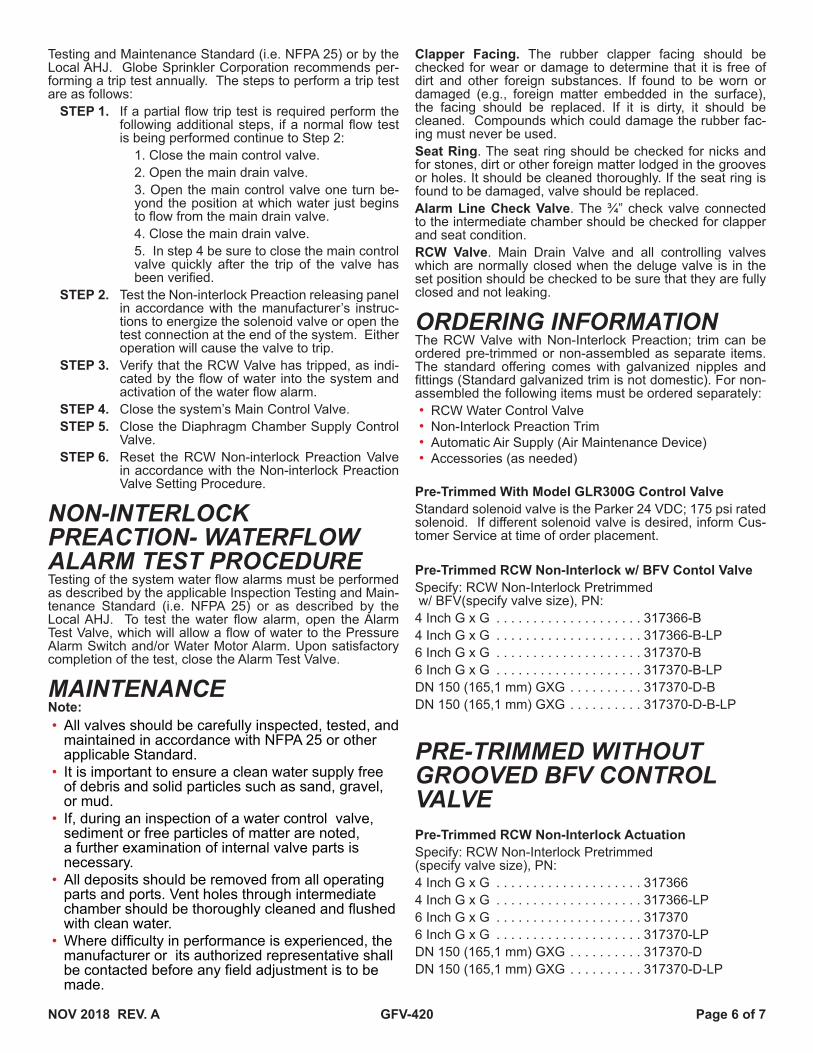
ITEM NO. PART NO. DESCRIPTION QTY. ITEM NO. PART NO. DESCRIPTION QTY.1 310802-G 2" x 3" GALV. NIPPLE 1 33 311224-G 3/4" x 1/2" GALV. STREET ELBOW 1
2 311208-G 2" 90° GALV. ELBOW 1 34 311801 1" CHECK VALVE (FxF) 1
3 310306-G 1/2" x 4" GALV. NIPPLE 4 35 311314-G 1/2" x 1/2" x 1/4" GALV. TEE 2
4 310301-G 1/2" x 1 1/2" GALV. NIPPLE 7 37 G5118026 SOLENOID VALVE WITH 24V DC COIL 1
5 310305-G 1/2" x 3 1/2" GALV. NIPPLE 2 38 317395 1/2" RESTRICTOR 1
6 323300 VELOCITY CHECK VALVE 1 39 311404-G 3/4" GALV. UNION 1
7 311696-R 1/2" BALL VALVE MXF - RED HANDLE 2 40 310401-G 3/4" x 2" GALV. NIPPLE 1
8 311313-G 3/4" x 1/2" x 3/4" GALV. TEE 1 41 311794-GR 1/2" BALL VALVE MxM - GREEN HANDLE 1
9 317398 DRIP CUP ASSEMBLY 1 42 310308-G 1/2" x 5" GALV. NIPPLE 3
11 310413-G 3/4" x 1 1/2" GALV. NIPPLE 4 43 311683 1/4" 3-WAY VALVE 2
12 310105-G 1/4" x 3 1/2" GALV. NIPPLE 1 44 1340104 PS-10-2 ALARM SWITCH 1
13 311001-G 1/4" GALV. PLUG 3 45 1340404 PS-40-2 ALARM SWITCH 1
14 300119-D 3-1/2" WATER GAUGE (300PSI) 2 46 310304-G 1/2" x 3" GALV. NIPPLE 1
15 300120-D 3-1/2" AIR GAUGE (250PSI) 1 47 311203-G 1/2" GALV. ELBOW 5
16 311210-G 1/2" GALV. STREET ELBOW 2 48 311207-G 1" GALV. STREET ELBOW 1
17 300111-G 1/2" GALV. CROSS 2 49 311799-R 2" BALL VALVE (FxF) - RED HANDLE 1
18 311004-G 3/4" GALV. PLUG 1 50 310800-G 2" CLOSE GALV. NIPPLE 2
19 311786 3/4" CHECK VALVE MxF 1 51 311338-G 2" x 2" x 1" GALV. TEE 1
20 311403-G 1/2" GALV. UNION 4 52 310501-G 1" x 2" GALV. NIPPLE 2
21 311305-G 1/2" x 1/4" x 1/2" GALV. TEE 4 54 310302-G 1/2" x 2" GALV. NIPPLE 2
22 310161 1/4" TUBE CONNECTOR 1 55 310101-G 1/4" x 1 1/2" GALV. NIPPLE 1
23 M-320604 1/4" COPPER TUBE - 56 317554 DRY PILOT ACTUATOR 1
24 310346 1/2" ELBOW TUBE CONNECTOR 1 57 311303-G 1/2" GALV. TEE 1
25 310164 1/2" TUBE CONNECTOR 2 62 317445 1/4" PRESSURE RELIEF VALVE (ADJ. PSI) FACTORY SET @ 45PSI 1
26 M-320591 1/2" COPPER TUBE - 66 310310-G 1/2" x 6" GALV. NIPPLE 1
27 317397 1/2" Y-STRAINER 1 72 311802 1/2" CHECK VALVE MxF 1
28 317396 1/2" SPRING LOADED CHECK VALVE 1 73 310318-G 1/2" x 12" GALV. NIPPLE 1
29 311794-R 1/2" BALL VALVE MxM - RED HANDLE 1 78 311696-GR 1/2" BALL VALVE MxF - GREEN HANDLE 1
31 300112-G 3/4" GALV. CROSS 1 79 310110-G 1/4" x 6" GALV. NIPPLE 1
32 311212-G 3/4" x 1/2" GALV. REDUCING ELBOW 1 83 310312-G 1/2" x 9" GALV. NIPPLE
TO DRIPCUP
TO DRIPCUP
26
54
54
25
47
CUPTO DRIP
716
43
20
7935
1111
83
8
429
42
5
14
21
48
9
38
16
50
32
26
12
24
28
TO DRIPCUP
27
49
346
47
2
72
47
50
51
1
52
34 52
78
25
13
4
623942
37
42
7
66
21
22
5
19
11
4031
20
73
4
33
21
20
4
15
21
18
35
44
233 45
11
47
17
6
13
4
4
4
20
14
56
57
3
3
43
47
55
13
2617
41
FROMAIR MAINTENANCEDEVICE
FROMAIR MAINTENANCE
DEVICE
TO OPTIONALWATER MOTOR ALARM
NOV 2018 REV. A GFV-420 Page 4 of 7
ITEM NO. PART NO. DESCRIPTION QTY. ITEM NO. PART NO. DESCRIPTION QTY.1 310802-G 2" x 3" GALV. NIPPLE 1 33 311224-G 3/4" x 1/2" GALV. STREET ELBOW 1
2 311208-G 2" 90° GALV. ELBOW 1 34 311801 1" CHECK VALVE (FxF) 1
3 310306-G 1/2" x 4" GALV. NIPPLE 2 35 311314-G 1/2" x 1/2" x 1/4" GALV. TEE 2
4 310301-G 1/2" x 1 1/2" GALV. NIPPLE 6 37 G5118026 SOLENOID VALVE WITH 24V DC COIL 1
5 310305-G 1/2" x 3 1/2" GALV. NIPPLE 2 38 317395 1/2" RESTRICTOR 1
6 323300 VELOCITY CHECK VALVE 1 39 311404-G 3/4" GALV. UNION 1
7 311696-R 1/2" BALL VALVE MxF - RED HANDLE 2 40 310401-G 3/4" x 2" GALV. NIPPLE 1
8 311313-G 3/4" x 1/2" x 3/4" GALV. TEE 1 41 311794-GR 1/2" BALL VALVE MxM - GREEN HANDLE 1
9 317398 DRIP CUP ASSEMBLY 1 42 310308-G 1/2" x 5" GALV. NIPPLE 4
11 310413-G 3/4" x 1 1/2" GALV. NIPPLE 3 43 311683 1/4" 3-WAY VALVE 2
12 310105-G 1/4" x 3 1/2" GALV. NIPPLE 1 44 1340104 PS-10-2 ALARM SWITCH 1
13 311001-G 1/4" GALV. PLUG 3 45 1340404 PS-40-2 ALARM SWITCH 1
14 300119-D 3-1/2" WATER GAUGE (300PSI) 2 46 310304-G 1/2" x 3" GALV. NIPPLE 2
15 300120-D 3-1/2" AIR GAUGE (250PSI) 1 47 311203-G 1/2" GALV. ELBOW 5
16 311210-G 1/2" GALV. STREET ELBOW 2 48 311207-G 1" GALV. STREET ELBOW 1
17 300111-G 1/2" GALV. CROSS 2 49 311799-R 2" BALL VALVE (FxF) - RED HANDLE 1
18 311004-G 3/4" GALV. PLUG 1 50 310800-G 2" CLOSE GALV. NIPPLE 2
19 311786 3/4" CHECK VALVE MxF 1 51 311338-G 2" x 2" x 1" GALV. TEE 1
20 311403-G 1/2" GALV. UNION 4 52 310501-G 1" x 2" GALV. NIPPLE 2
21 311305-G 1/2" x 1/4" x 1/2" GALV. TEE 4 54 310302-G 1/2" x 2" GALV. NIPPLE 3
22 310161 1/4" TUBE CONNECTOR 1 55 310101-G 1/4" x 1 1/2" GALV. NIPPLE 1
23 M-320604 1/4" COPPER TUBE - 56 317554 DRY PILOT ACTUATOR 1
24 310346 1/2" ELBOW TUBE CONNECTOR 1 57 311303-G 1/2" GALV. TEE 1
25 310164 1/2" TUBE CONNECTOR 2 62 317445 1/4" PRESSURE RELIEF VALVE (ADJ. PSI) FACTORY SET @ 45PSI 1
26 M-320591 1/2" COPPER TUBE - 66 310310-G 1/2" x 6" GALV. NIPPLE 1
27 317397 1/2" Y-STRAINER 1 68 310402-G 3/4" x 2 1/2" GALV. NIPPLE 1
28 317396 1/2" SPRING LOADED CHECK VALVE 1 72 311802 1/2" CHECK VALVE MxF 1
29 311794-R 1/2" BALL VALVE MxM - RED HANDLE 1 73 310318-G 1/2" x 12" GALV. NIPPLE 1
31 300112-G 3/4" GALV. CROSS 1 78 311696-GR 1/2" BALL VALVE MXF - GREEN HANDLE 1
32 311212-G 3/4" x 1/2" GALV. REDUCING ELBOW 1 79 310110-G 1/4" x 6" GALV. NIPPLE 1
82 310320-G 1/2" x10" GALV. NIPPLE 1
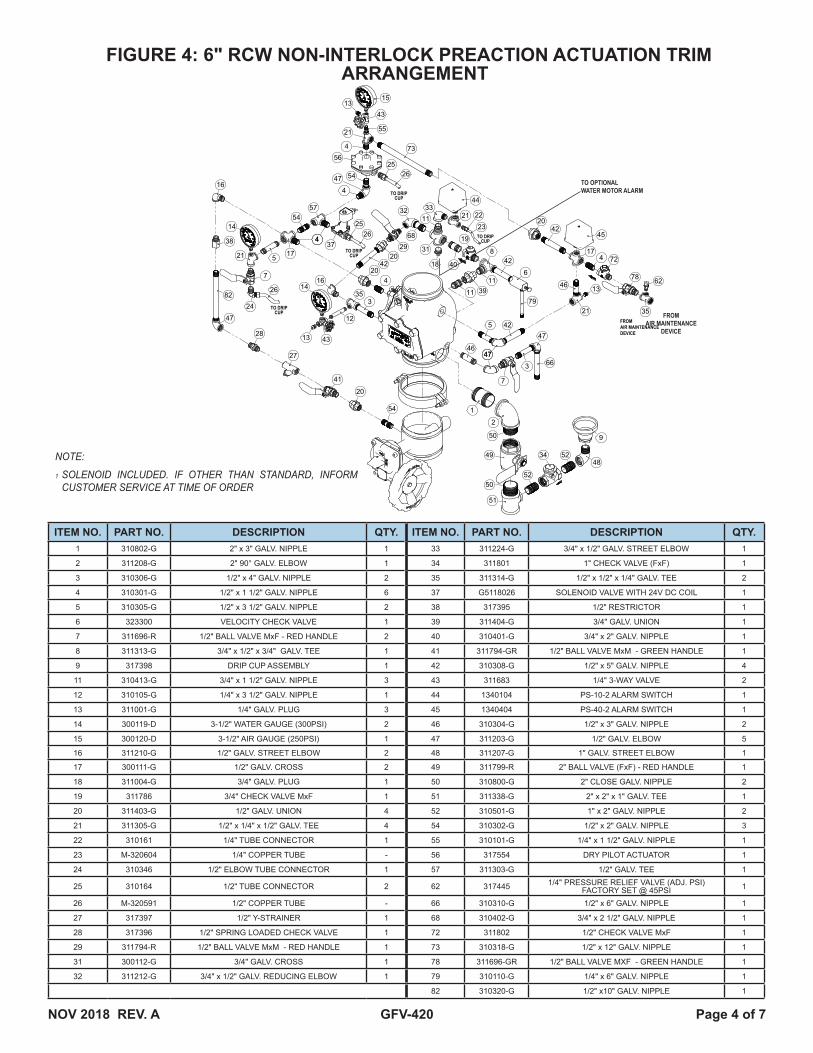
FIGURE 4: 6" RCW NON-INTERLOCK PREACTION ACTUATION TRIM ARRANGEMENT
NOTE:
1 SOLENOID INCLUDED. IF OTHER THAN STANDARD, INFORM CUSTOMER SERVICE AT TIME OF ORDER
TO DRIPCUP
TO DRIPCUP
DETNO PARTNO DESCRIPTION QTY.1 310802-G 2" x 3" GALV. NIPPLE 12 311208-G 2" GALV. ELBOW 13 310306-G 1/2" x 4" GALV. NIPPLE 24 310301-G 1/2" x 1 1/2" GALV. NIPPLE 65 310305-G 1/2" x 3 1/2" GALV. NIPPLE 26 323300 VELOCITY CHECK VALVE 17 311696-R 1/2" BALL VALVE (MxF) - RED HANDLE 28 311313-G 3/4" x 1/2" x 3/4" GALV. TEE 19 317398 DRIP CUP ASSEMBLY 111 310413-G 3/4" x 1 1/2" GALV. NIPPLE 312 310105-G 1/4" x 3 1/2" GALV. NIPPLE 113 311001-DG 1/4" DOM. GALV. PLUG 314 300119-D 3 1/2" WATER GAUGE (300PSI) 215 300120-D 3 1/2" AIR GAUGE (250PSI) 116 311210-G 1/2" GALV. STREET ELBOW 217 300111-G 1/2" GALV. CROSS 218 311004-G 3/4" GALV. PLUG 119 311786 3/4" CHECK VALVE (MxF) 120 311403-G 1/2" GALV. UNION 421 311305-G 1/2" x 1/4" x 1/2" GALV. TEE 422 310161 1/4" TUBE CONNECTOR 123 M-320604 1/4" COPPER TUBE -24 310346 1/2" ELBOW TUBE CONNECTOR 125 310164 1/2" TUBE CONNECTOR 226 M-320591 1/2" COPPER TUBE -27 317397 1/2" Y-STRAINER 128 317396 1/2" SPRING LOADED CHECK VALVE 129 311794-R 1/2" BALL VALVE (MxM) - RED HANDLE 131 300112-G 3/4" GALV. CROSS 132 311212-G 3/4" x 1/2" GALV. REDUCING ELBOW 133 311224-G 3/4" x 1/2" GALV. STREET ELBOW 134 311801 1" CHECK VALVE (FxF) 135 311314-G 1/2" x 1/2" x 1/4" GALV. TEE 237 G5118026 SOLENOID VALVE WITH 24V DC COIL 138 317395 1/2" RESTRICTOR 139 311404-G 3/4" GALV. UNION 140 310401-G 3/4" x 2" GALV. NIPPLE 1
41 311794-GR 1/2" BALL VALVE (MxM) - GREEN HANDLE 1
42 310308-G 1/2" x 5" GALV. NIPPLE 443 311683 1/4" 3-WAY VALVE 244 1340104 PS-10-2 ALARM SWITCH 145 1340404 PS-40-2 ALARM SWITCH 146 310304-G 1/2" x 3" GALV. NIPPLE 247 311203-G 1/2" GALV. ELBOW 548 311207-G 1" GALV. STREET ELBOW 149 311799-R 2" BALL VALVE (FxF) - RED HANDLE 150 310800-G 2" CLOSE GALV. NIPPLE 251 311338-G 2" x 2" x 1" GALV. TEE 152 310501-G 1" x 2" GALV. NIPPLE 254 310302-G 1/2" x 2" GALV. NIPPLE 355 310101-G 1/4" x 1 1/2" GALV. NIPPLE 156 317554 DRY PILOT ACTUATOR 157 311303-G 1/2" GALV. TEE 1
62 317445 1/4" PRESSURE RELIEF VALVE (ADJ. PSI) FACTORY SET @ 45PSI 1
66 310310-G 1/2" x 6" GALV. NIPPLE 168 310402-G 3/4" x 2 1/2" GALV. NIPPLE 172 311802 1/2" CHECK VALVE MxF (NINGBO) 173 310318-G 1/2" x 12" GALV. NIPPLE 1
78 311696-GR 1/2" BALL VALVE (MxF) - GREEN HANDLE 1
79 310110-G 1/4" x 6" GALV. NIPPLE 182 310320-G 1/2" x 10" GALV. NIPPLE 1
32
2625
16
43
14
57
14
47
35
50
CUPTO DRIP
15
12
13
18
31
40
11
16
294
4
8
25
3
41
17
20
34
4
19
43
7
4
13
TO DRIPCUP37
47 54
55
27
4
20
54
26
73
1
51
5248
52
21
56
28
26
24
9
4220
23
21
21
5
44
22
42
78
4
42
13
35
47
66
11 626
46
17
79
33
68
11 39
21
20
3
4542
7
47
72
5
46
82
47
2
50
49
38
54
FROMAIR MAINTENANCEDEVICE
FROMAIR MAINTENANCE
DEVICE
TO OPTIONALWATER MOTOR ALARM

NOV 2018 REV. A GFV-420 Page 5 of 7
INSTALLATION AND MAINTENANCEINSTALLATIONProper operation of the RCW Valve (i.e., opening of the RCW Valve as during a fire condition) is highly dependent on the correct installation of the trim. It is necessary to in-stall the trim components as described in the figures above for the valve to function properly. Failure to do so may prevent the valve from functioning and could void Listings, Approvals, and/or the manufacturer's warranty. All tubing directed to the "drip cup" must have smooth bends. Abrupt changes in direction or kinks in the tubing could result in a restriction of flow and an adverse effect on the functionality of the valve.The Model RCW Valve must be installed in an accessible and visible location, which is maintained at or above a mini-mum temperature of 40ºF (4ºC). The RCW Valve must be installed in the vertical orientation.All valves must be installed in accordance with the appropri-ate installation standard (i.e. NFPA 13, NFPA 15 or other). All electrical connections must be made per the applicable installation standard and/or the National Electric Code (i.e. NFPA 70, NFPA 72 or other). Proper hydrostatic test procedure must be followed per NFPA 13. The velocity check valve must be replaced with a plug temporarily, the pressure chamber must be vented dur-ing the hydrostatic test procedure by opening the manual release valve and the clapper must be latched in the open position.
NON-INTERLOCK PREACTION VALVE SETTING PROCEDUREThe following steps are to be followed for initial set-ting of the Model RCW non-interlock preaction system valve, after a trip test of the fire protection system or, after any system operation.
STEP 1. Close the main control valve.STEP 2. Close the pressure chamber supply control
valve and the system air supply valve.STEP 3. Open the main drain valve, lower body drain
valve, and all low point drain valves and aux-iliary drain valves on the system. Open the manual emergency release control valve. De-press the plunger of the automatic drain valve to verify that it is not under pressure and that the system piping is completely drained. After system is completely drained, close all low point and auxiliary drain valves that were open. The manual emergency release control valve and main drain valve should remain open until directed in the following steps.
STEP 4. Depress the reset plunger located at the top of the pressure chamber to reset the clapper of the RCW valve (the sound of the clapper fall-ing into position should be heard). Close the manual emergency release control valve.
STEP 5. Open the remote test valve. Replace any oper-ated automatic sprinklers that operated with the same type, i.e. Orientation, orifice, temperature, and thermal sensitivity. Close the remote test valve.
STEP 6. The detection system is to be cleared and reset in accordance with the detection system and/or control panel manufacturer’s instructions. Once reset, verify the solenoid valve is closed (de-
energized). When closed, the solenoid valve should have no magnetic charge on the nut on the top of the coil. Test the nut to make sure it is has no magnetic charge by contacting the nut with a conductive item such as a screwdriver. If still magnetized, the detection system/panel is not properly set for service.
STEP 7. Open the system air supply valve to re-estab-lish normal system air pressure.
STEP 8. Open the manual emergency release control valve and then the pressure chamber supply control valve. Slowly close the manual emer-gency release control valve and allow pressure to build up in the pressure chamber, up to the dry pilot actuator and solenoid valve.
STEP 9. Observe all drain tubing at the drip cup. If any leakage is observed, the source of the leakage must be identified and corrected.
STEP 10. Partially open the main control valve. Slowly close the main drain valve when water dis-charges from the drain connection. Observe the supply pressure gauge and the pressure chamber gauge, they should indicate the same pressure reading. Depress the plunger on the automatic drip check valve for leaks. If leakage is apparent, the cause of the leakage must be identified and corrected. If there are no leaks, open the system control valve fully.
STEP 11. Clear/reset the releasing control panel to clear any supervisory conditions that connected to the system control valve. Once the panel is reset and clear, the system is set for service.
TESTINGReference NFPA 25, Standard for the Inspection, Test-ing and Maintenance of Water-Based Fire Protection Systems. Before proceeding with any tests involving water flow, the following precautions need to be taken:
STEP 1. Check the location where the test connection discharges to make sure that all is clear and that there is no possibility of the water flow causing damage or injury.
STEP 2. Check the end of the test connection to make sure that it is unobstructed. To achieve a satis-factory test, there must be an unrestricted flow of water when the test valve is wide open.
STEP 3. Check for alarm connections to a central sta-tion or fire department. If such connections are found, give proper notice to the signal receiving station before proceeding with the test.
Note: A main drain test may also operate local fire alarms unless they are tem-porarily disabled.
NON-INTERLOCK PREACTION TRIP TEST PROCEDUREProper operation of the RCW Valve (i.e., opening of the RCW Valve as during a fire condition) must be verified, at or more frequently than described by the applicable Inspection
NOV 2018 REV. A GFV-420 Page 6 of 7
Testing and Maintenance Standard (i.e. NFPA 25) or by the Local AHJ. Globe Sprinkler Corporation recommends per-forming a trip test annually. The steps to perform a trip test are as follows:
STEP 1. If a partial flow trip test is required perform the following additional steps, if a normal flow test is being performed continue to Step 2:
1. Close the main control valve. 2. Open the main drain valve. 3. Open the main control valve one turn be-yond the position at which water just begins to flow from the main drain valve. 4. Close the main drain valve.5. In step 4 be sure to close the main control valve quickly after the trip of the valve has been verified.
STEP 2. Test the Non-interlock Preaction releasing panel in accordance with the manufacturer’s instruc-tions to energize the solenoid valve or open the test connection at the end of the system. Either operation will cause the valve to trip.
STEP 3. Verify that the RCW Valve has tripped, as indi-cated by the flow of water into the system and activation of the water flow alarm.
STEP 4. Close the system’s Main Control Valve.STEP 5. Close the Diaphragm Chamber Supply Control
Valve.STEP 6. Reset the RCW Non-interlock Preaction Valve
in accordance with the Non-interlock Preaction Valve Setting Procedure.
NON-INTERLOCK PREACTION- WATERFLOW ALARM TEST PROCEDURETesting of the system water flow alarms must be performed as described by the applicable Inspection Testing and Main-tenance Standard (i.e. NFPA 25) or as described by the Local AHJ. To test the water flow alarm, open the Alarm Test Valve, which will allow a flow of water to the Pressure Alarm Switch and/or Water Motor Alarm. Upon satisfactory completion of the test, close the Alarm Test Valve.
MAINTENANCENote:• All valves should be carefully inspected, tested, and
maintained in accordance with NFPA 25 or other applicable Standard.
• It is important to ensure a clean water supply free of debris and solid particles such as sand, gravel, or mud.
• If, during an inspection of a water control valve, sediment or free particles of matter are noted, a further examination of internal valve parts is necessary.
• All deposits should be removed from all operating parts and ports. Vent holes through intermediate chamber should be thoroughly cleaned and flushed with clean water.
• Where difficulty in performance is experienced, the manufacturer or its authorized representative shall be contacted before any field adjustment is to be made.
Clapper Facing. The rubber clapper facing should be checked for wear or damage to determine that it is free of dirt and other foreign substances. If found to be worn or damaged (e.g., foreign matter embedded in the surface), the facing should be replaced. If it is dirty, it should be cleaned. Compounds which could damage the rubber fac-ing must never be used.Seat Ring. The seat ring should be checked for nicks and for stones, dirt or other foreign matter lodged in the grooves or holes. It should be cleaned thoroughly. If the seat ring is found to be damaged, valve should be replaced.Alarm Line Check Valve. The ¾” check valve connected to the intermediate chamber should be checked for clapper and seat condition.RCW Valve. Main Drain Valve and all controlling valves which are normally closed when the deluge valve is in the set position should be checked to be sure that they are fully closed and not leaking.
ORDERING INFORMATIONThe RCW Valve with Non-Interlock Preaction; trim can be ordered pre-trimmed or non-assembled as separate items. The standard offering comes with galvanized nipples and fittings (Standard galvanized trim is not domestic). For non-assembled the following items must be ordered separately:• RCW Water Control Valve• Non-Interlock Preaction Trim• Automatic Air Supply (Air Maintenance Device)• Accessories (as needed)
Pre-Trimmed With Model GLR300G Control ValveStandard solenoid valve is the Parker 24 VDC; 175 psi rated solenoid. If different solenoid valve is desired, inform Cus-tomer Service at time of order placement.
Pre-Trimmed RCW Non-Interlock w/ BFV Contol ValveSpecify: RCW Non-Interlock Pretrimmed w/ BFV(specify valve size), PN:4 Inch G x G . . . . . . . . . . . . . . . . . . . . 317366-B4 Inch G x G . . . . . . . . . . . . . . . . . . . . 317366-B-LP6 Inch G x G . . . . . . . . . . . . . . . . . . . . 317370-B6 Inch G x G . . . . . . . . . . . . . . . . . . . . 317370-B-LPDN 150 (165,1 mm) GXG . . . . . . . . . . 317370-D-BDN 150 (165,1 mm) GXG . . . . . . . . . . 317370-D-B-LP
PRE-TRIMMED WITHOUT GROOVED BFV CONTROL VALVEPre-Trimmed RCW Non-Interlock ActuationSpecify: RCW Non-Interlock Pretrimmed (specify valve size), PN:4 Inch G x G . . . . . . . . . . . . . . . . . . . . 3173664 Inch G x G . . . . . . . . . . . . . . . . . . . . 317366-LP6 Inch G x G . . . . . . . . . . . . . . . . . . . . 3173706 Inch G x G . . . . . . . . . . . . . . . . . . . . 317370-LPDN 150 (165,1 mm) GXG . . . . . . . . . . 317370-DDN 150 (165,1 mm) GXG . . . . . . . . . . 317370-D-LP
NOV 2018 REV. A GFV-420 Page 7 of 7
NON-ASSEMBLED• Valve body ordered separately • Solenoid Valve Included• Trim Kit includes extra pieces to accommodate different
size valves
RCW Water Control Valve Specify: RCW Valve Only (specify valve size)4 inch RCW GxG . . . . . . . . . . . . . . . . . 3174004 inch RCW GxG . . . . . . . . . . . . . . . . . 317400-LP6 inch RCW GxG . . . . . . . . . . . . . . . . . 3175506 inch RCW GxG . . . . . . . . . . . . . . . . . 317550-LPDN 150 (165,1 mm) RCW GXG . . . . . 317550-DDN 150 (165,1 mm) RCW GXG . . . . . 317550-D-LP
RCW Non-Interlock Trim Kit 4 inch or 6 inch or DN 150Specify: RCW Non-Interlock Trim Kit, PNNon-Interlock Trim Kit . . . . . . . . . . . . . 317365Non-Interlock Trim Kit . . . . . . . . . . . . . 317365-LP
Solenoid ValveA Solenoid Valve compatible with the anticipated maximum water supply pressure and releasing panel when order-ing a non interlock actuation trim. Refer to Technical Data Sheet GFV565 for ordering information. Specify: 24 VDC, (175 psi, 250 psi or 300 psi) Solenoid Valve:ASCO 175 psi (12 Bar) UL/FM . . . . . . G8219G207ASCO 300 psi (20.7 Bar) UL/FM . . . . . GHV432449001 *Skinner 175 psi (12 Bar) UL/FM. . . . . G5118026Skinner 250 psi (17.2 Bar) UL/FM . . . . G5118024
*Standard
Model H-1, H-2 or H-3 Air Maintenance DeviceSpecify: Model (Specify Model) Air Maintenance Device (see Part Number below)H-1 . . . . . . . . . . . . . . . . . . . . . . . . . . . . 320585H-2 . . . . . . . . . . . . . . . . . . . . . . . . . . . . 320595H-3 . . . . . . . . . . . . . . . . . . . . . . . . . . . . 320600See Technical Literature G-1 and G-2 for more information on Air Maintenance DevicesNote: • 300 psi (20.6 Bars) Pressure Gauges Standard (600 psi
(41.2 Bars)) Ordered Separately)PN . . . . . . . . . . . . . . . . . . . . . . . . . . . . 300121-D
NOTE:
See trim drawings for trim replacement part numbers
See Technical Data Sheet GFV200 for RCW Valve replacement part numbers
GLOBE® PRODUCT WARRANTYGlobe agrees to repair or replace any of its own manufac-tured products found to be defective in material or work-manship for a period of one year from date of shipment.For specific details of our warranty please refer to Price List Terms and Conditions of Sale (Our Price List).
4077 Airpark Dr. Standish, MI 48658 Ph. 989-846-4583
Technical Support 1-800-248-0278