
MODEL : PP 1500 SC - PowerGen€¦ · MODEL : PP 1500 SC GENERATING SET ... KTA50-GS8 Advantage...
21
MODEL : PP 1500 SC GENERATING SET PERFORMANCE 50Hz 60Hz VOLTAGE V400 PHASES Three PRIME RATED POWER 1500kVA STANDBY RATED POWER 1650kVA POWER FACTOR 0.80 PF FUEL USAGE @ 75% 238.0 L/hr Powered by:
Transcript of MODEL : PP 1500 SC - PowerGen€¦ · MODEL : PP 1500 SC GENERATING SET ... KTA50-GS8 Advantage...
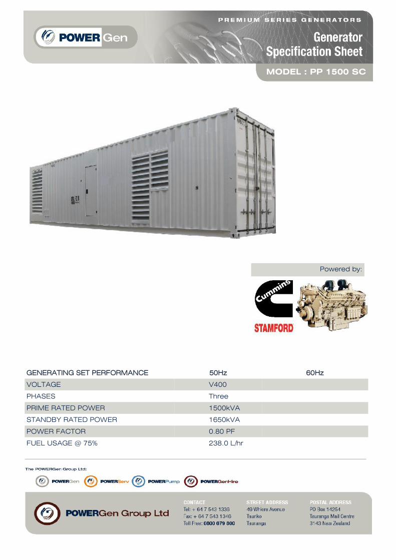
MODEL : PP 1500 SC
GENERATING SET PERFORMANCE 50Hz 60Hz
VOLTAGE V400
PHASES Three
PRIME RATED POWER 1500kVA
STANDBY RATED POWER 1650kVA
POWER FACTOR 0.80 PF
FUEL USAGE @ 75% 238.0 L/hr
Powered by:

ENGINE CUMMINS KTA50-GS8
PERFORMANCE 50Hz 60Hz
BASELOAD RATED POWER N/A
PRIME RATED POWER 1287KWm
STANDBY RATED POWER 1429KWm
FUEL CONSUMPTION 309 L/hr @ 100%238 L/hr @ 75%167 L/hr @ 50%
TYPE Diesel 4 stroke
ASPIRATION
INJECTION TYPE Direct injection
ENGINE GOVERNOR Electronic governor
CYLINDERS AND ARRANGEMENT 16 Vee
BORE AND STROKE 159mm x 159mm
COMPRESSION RATIO 14.9:1
ELECTRICAL SYSTEM VOLTAGE 24 volt
BATTERY TYPE Lead acid, 24V
DERATING FOR TEMPERATURE 40deg C
DERATING FOR ALTITUDE 1000m
DERATING FOR HUMIDITY 90%
Turbocharged and after cooled
ENGINE

ALTERNATOR STAMFORD
PERFORMANCE 50Hz 60Hz
MODEL PI734G
BASELOAD RATED POWER 40 deg C 2050kVA
PRIME RATED POWER 40 deg C 2200kVA
STANDBY RATED POWER 40 deg C 1295kVA
STANDBY RATED POWER 27 deg C 2360kVA
EFFICIENCY 97%
STANDARD WING CONNECTIONS Star Delta
EXCITER
POLES 4 poles
PHASES Three phases
WIRES 6 leads
VOLTAGE REGULATION +/- 0.5%
INSULATION CLASS Class H
ENCLOSURE IP23
MAXIMUM OVERSPEED 150%
STANDARD AVR MODEL MX321
OPTIONAL AVR MODEL TBA
DERATING FOR TEMPERATURE 40 deg C
DERATING FOR ALTITUDE 1000mm
Separately excited by P.M.G
ALTERNATOR

DIMENSIONS
DIMENSIONS AND CAPACITY
STANDARD MODELS
INTEGATED FUEL TANKCAPACITY
WEIGHT DIMENSIONS
STANDARD OPTIONAL KG LENGTH WIDTH HEIGHT
SOUNDPROOFED TYPE75dB(A)+/-3dB(A) at7 metre
TBA TBA 21400kg 12192mm 2500mm 2900mm
GENERATOR SET EQUIPMENT
STANDARD MODELS
Heavy duty steel base frame Pad type anti– vibration dampers Integrated fuel tank, base mounted 24V battery Key start switch Emergency stop button

AUTOMATIC MODELS – EQUIPMENT
AUTOMATIC MODELS – PROTECTORS
AUTOMATIC MODELS – INSTRUMENTATION
CONTROLLER
ABB/Scheider 3 pole 2500A ACB circuit breaker with 24V shunt trip, Electronic control unit ComAp
InteliGen-NT, Control panel box key, Emergency Stop button, Water jacket heater , Battery charger,
Alternator Anti-condensation heater.
Low oil pressure, Low fuel level Low voltage, High Coolant Temperature, Over/Under battery voltage,
Belt breakage, ROCOF, Reverse Power3 phase integrated generator protections (U + f), IDMT
overcurrent + Shortcurrent protection, Overload protection, Reverse power protection, Earth fault
protection, 3 phase integrated mains protections (U + f), Vector shift protection, All binary/analogue
inputs free configurable for various protection types: HistRecOnly Alarm Only /Warning / Off load /
Slow stop / Breaker Open& Cooldown / Shutdown / Mains protect / Sensor fail. Additional 160
programmable protections configurable for any measured value to create customer-specific
Protections.
Analogue meters for Voltmeter , Ammeter (3 phases) , Frequency meter , Hour-meter , Batteryvoltage meter, Analogue gauges for Fuel level .Water Temp, oil Pressure, Battery charging current,Battery voltage.

OUTPUT POWER FUEL CONSUMPTION
% kWm BHPkg/
kWm·hlb/
BHP·hlitre/hour
U.S. Gal/hour
OVERLOAD POWER
100 1429 1915 0.206 0.338 345 91.2
PRIME POWER
100 1287 1725 0.204 0.336 309 81.6
75 965 1294 0.210 0.345 238 62.8
50 644 863 0.221 0.363 167 44.1
25 322 431 0.232 0.383 88 23.3
CONVERSIONS: (Litres = U.S. Gal x 3.785) (kWm = BHP x 0.746) (U.S. Gal = Litres x 0.2642) (BHP = Engine kWm x 1.34)
Data shown above represent gross engine performance capabilities obtained and corrected in accordance with ISO-3046 conditions of 100 kPa (29.53 in. Hg.)barometric pressure [110 m (361 ft.) altitude], 25°C (77°F) air inlet temperature, and relative humidity of 30% with No. 2 diesel or a fuel corresponding to ASTM D2. See reverse side for application rating guidelines.The fuel consumption data is based on No. 2 diesel fuel weight at 0.85 kg/litre (7.1 lbs./U.S. gal).
Power output curves are based on the engine operating with fuel system, water pump and lubricating oil pump; not included are battery charging alternator, fan, optional equipment and driven components.
TECHNICAL DATA DEPT. CERTIFIED WITHIN 5% CHIEF ENGINEER
Engine Performance Data @ 1500 RPM
Engine Performance Data @ 1800 RPM
Not Available at 1800 RPMNot Available at 1800 RPM
Engine Speed Overload Power Rating Prime Power Rating
RPM kWm BHP kWm BHP
1500 1429 1915 1287 1725
1800 ----- ----- ----- -----
Gross Engine Power Output - kWm
Litre/hour
Curve Number: FR-6261 Engine Critical Parts List: 2354 (1P/2L), 2859 (2P/2L) Date: 21Jan02
Displacement : 50.3 litre (3067 in3 ) Bore : 159 mm (6.25 in.) Stroke : 159 mm (6.25 in.)
No. of Cylinders : 16 Aspiration : Turbocharged and Low Temperature Aftercooled
KTA50-GS8 Advantage Data SheetCummins Inc. Columbus, Indiana 47201

POWER RATING APPLICATION GUIDELINESFOR EMERGENCY STANDBY ENGINES FOR APPLICATION IN
CORPORATE GENERATOR SETS ONLY
These guidelines have been formulated to ensure proper application of generator drive engines in Cummins corporate generator set installations. Generator drive engines are not designed for and shall not be used in variable speed D.C. generator set applications.
Applicable for supplying emergency power for the duration of the utility power outage. No overload capability is available for this standby rating. Under no condition is an engine allowed to operate in parallel with the public utility at the Emergency Standby Power rating. This rating should be applied where reliable utility power is available. An emergency standby rated engine should be sized for a maximum of an 70% typical load factor and 200 hours of operation per year. This includes a maximum of 1 hour in a 12 hour period at the Emergency Standby Power rating. Emergency Standby rating should never be applied except in true emergency power outages. Negotiated power outages contracted with a util-ity company are not considered an emergency.
0
5
10
15
20
25
30
35
40
0 500 1000 1500 2000 2500
Altitude (meters)
Der
ate
(% o
f R
ated
Po
wer
)
50
40
25
Ambient Temp (°C)
35
KTA50-GS8 Advantage Data SheetCummins Inc. Columbus, Indiana 47201
Reference Standards:BS-5514 and D IN-6271 standards are based on ISO-3046.
Operation At Elevated Temperature And Altitude:
For sustained operation above these conditions, derate by an additional 4.6% per 300m (1000ft) and 12% per 10°C (18°F)
NOTE: Derates shown are based on 15” H20 air in take restriction and 2 ” Hg exhaust back pressure .

DATA SHEET : DS-6261ENGINE MODEL : KTA50-GS8 CONFIGURATION NUMBER : D283022DX02 DATE : 21Jan02
PERFORMANCE CURVE : FR-6261
INSTALLATION DIAGRAM CPL NUMBER • Fan to Flywheel (1P/2L) : 3170289 • Engine Critical Parts List (1P/2L) : 2354 • Fan to Flywheel (2P/2L) : 3626419 • Engine Critical Parts List (2P/2L) : 2859
GENERAL ENGINE DATAType................................................................................................................................................................ 4-Cycle; 60° Vee; 16-Cylinder DieselAspiration........................................................................................................................................................ Turbocharged & Low Temp. AftercooledBore x Stroke ..............................................................................................................— in x in (mm x mm) 6.25 x 6.25 (159 x 159)Displacement ..............................................................................................................................— in3
(liter) 3067 (50.3)Compression Ratio........................................................................................................................................ 14.9 : 1Dry Weight
Fan to Flywheel Engine......................................................................................................... — lb (kg) 11820 (5360)Wet Weight
Fan to Flywheel Engine......................................................................................................... — lb (kg) 12485 (5662)Moment of Inertia of Rotating Components • with FW 6009 Flywheel ........................................................................................... — lbm • ft2 (kg • m2) 271 (11.4) • with FW 6017 Flywheel............................................................................................ — lbm • ft2 (kg • m2) 515 (21.7)Center of Gravity from Rear Face of Flywheel Housing (FH 6024)......................................... — in (mm) 47.5 (1206)Center of Gravity Above Crankshaft Centerline........................................................................ — in (mm) 11.0 (279)Maximum Static Loading at Rear Main Bearing......................................................................... — lb (kg) 2000 (908)
ENGINE MOUNTINGMaximum Bending Moment at Rear Face of Block.......................................................... — lb • ft (N • m) 4500 (6100)
EXHAUST SYSTEMMaximum Back Pressure .............................................................................................. — in Hg (mm Hg) 2 (51)
AIR INDUCTION SYSTEMMaximum Intake Air Restriction • with Dirty Filter Element ........................................................................................ — in H2O (mm H2O) 25 (635) • with Clean Filter Element ...................................................................................... — in H2O (mm H2O) 15 (381)
COOLING SYSTEM (Low Temperature Aftercooling)Coolant Capacity — Engine Only.................................................................................... — US gal (liter) 43.5 (165)Maximum Coolant Friction Head External to Engine — 1500 rpm [High Flow] ..............— psi (kPa) 10 (70)
— 1500 rpm [Low Flow]...............— psi (kPa) 5 (35)Maximum Static Head of Coolant Above Engine Crank Centerline............................................ — ft (m) 60 (18.3)Standard Thermostat Modulating Range — High Flow (Jacket) ........................................... — °F (°C) 180 - 200 (82 - 93)
— Low Flow (Aftercooler)..................................... — °F (°C) 150 - 175 (66 - 79)Minimum Pressure Cap (For Cooling Systems with less than 2 m [6 ft.] Static Head) ........ — psi (kPa) 14 (96)Maximum Top Tank Temperature for Overload Power / Prime Power.................................... — °F (°C) 220 / 212 (104 / 100)Target Coolant Inlet Temperature to Aftercoolers @ 77 °F (25 °C) Ambient .......................... — °F (°C) 130 (55)Maximum Coolant Temperature to Aftercoolers — Overload Power / Prime Power............... — °F (°C) 160 / 150 (71 / 66)
LUBRICATION SYSTEMOil Pressure @ Idle Speed..................................................................................................... — psi (kPa) 20 (138)
@ Governed Speed.......................................................................................... — psi (kPa) 50 - 70 (345 - 483)Maximum Oil Temperature ......................................................................................................... — °F (°C) 250 (121)Oil Capacity with OP 6027 Oil Pan : High - Low............................................................... — US gal (liter) 47 - 39 (178 - 148)Total System Capacity (Including Bypass Filter) .............................................................. — US gal (liter) 54 (204)
FUEL SYSTEMType Injection System................................................................................................................................................ Direct Injection Cummins PTMaximum Restriction at PT Fuel Injection Pump — with Clean Fuel Filter.................. — in Hg (mm Hg) 4.0 (102)
— with Dirty Fuel Filter.................... — in Hg (mm Hg) 8.0 (203)Maximum Allowable Head on Injector Return Line
(Consisting of Friction Head and Static Head) — in Hg (mm Hg) 6.5 (165)Maximum Fuel Flow to Injection Pump...................................................................... — US gph (liter / hr) 151 (570)
KTA50-GS8 Advantage Data SheetCummins Inc. Columbus, Indiana 47201

ELECTRICAL SYSTEMCranking Motor (Heavy Duty, Positive Engagement)......................................................................................................... — volt 24Battery Charging System, Negative Ground............................................................................................................... — ampere 35Maximum Allowable Resistance of Cranking Circuit......................................................................................................... — ohm 0.002Minimum Recommended Battery Capacity
• Cold Soak @ 50°F (10°C) and Above............................................................................................................... — 0°F CCA 1280• Cold Soak @ 32°F to 50°F (0°C to 10°C).......................................................................................................... — 0°F CCA 1800• Cold Soak @ 0°F to 32°F (-18°C to 0°C)........................................................................................................... — 0°F CCA 1800
COLD START CAPABILITYMinimum Ambient Temperature for Aided (with Coolant Heater) Cold Start within 10 seconds ............................... — °F (°C) 50 (10)Minimum Ambient Temperature for Unaided Cold Start............................................................................................... — °F (°C) 45 (7)
PERFORMANCE DATAAll data is based on: • Engine operating with fuel system, water pump, lubricating oil pump, air cleaner and exhaust
silencer; not included are battery charging alternator, fan, and optional driven components.• Engine operating with fuel corresponding to grade No. 2-D per ASTM D975.• ISO 3046, Part 1, Standard Reference Conditions of:
Barometric Pressure : 100 kPa (29.53 in Hg) Air Temperature : 25 °C (77 °F)Altitude : 110 m (361 ft) Relative Humidity : 30%
Steady State Stability Band at any Constant Load .............................................................................................................. — % +/- 0.25Estimated Free Field Sound Pressure Level of a Typical Generator Set;
Excludes Exhaust Noise; at Rated Load and 7.5 m (24.6 ft); 1500 rpm................................................................ — dBA 92.4Exhaust Noise at 1 m Horizontally from Centerline of Exhaust Pipe Outlet Upwards at 45° ......................................... — dBA N.A.
OVERLOAD POWER PRIME POWER
Governed Engine Speed..............................................................— rpm 1500 1500Engine Idle Speed ....................................................................... — rpm 725 - 775 725 - 775Gross Engine Power Output...........................................— BHP (kWm) 1915 (1429) 1725 (1286)Brake Mean Effective Pressure...........................................— psi (kPa) 330 (2275) 299 (2062)Piston Speed.................................................................— ft / min (m / s) 1562 (7.9) 1562 (7.9)Friction Horsepower ......................................................... — HP (kWm) 155 (116) 155 (116)Engine Data with Dry Type Exhaust ManifoldIntake Air Flow ................................................................— cfm (liter / s) 3500 (1655) 3350 (1581)Exhaust Gas Temperature......................................................— °F (°C) 950 (510) 930 (499)Exhaust Gas Flow ..........................................................— cfm (liter / s) 9210 (4350) 8555 (4038)Air to Fuel Ratio ..................................................................... — air : fuel 23.2 : 1 24.5 : 1Radiated Heat to Ambient .....................................— BTU / min (kWm) 12000 (210) 10700 (299)Heat Rejection to Exhaust .....................................— BTU / min (kWm) 54200 (954) 47500 (835)Additional Engine Aftercooler Data (2 Pump / 2 Loop)Engine Jacket Coolant Flow at Stated Friction Head External to Engine:
• 4 psi Friction Head........................................... — US gpm (liter / s) 440 (27.8) 440 (27.8)• Maximum Friction Head .................................. — US gpm (liter / s) 400 (25.2) 400 (25.2)
Heat Rejection to Coolant (Aftercooler).................— BTU / min (kWm) 15600 (275) 12600 (221)Heat Rejection to Coolant (Engine).......................— BTU / min (kWm) 35000 (615) 32500 (571)Aftercooler Coolant Flow at Stated Friction Head External to Engine:.
• 2 psi Friction Head........................................... — US gpm (liter / s) 100 (6.3) 100 (6.3)• Maximum Friction Head .................................. — US gpm (liter / s) 95 (6.0) 95 (6.0)
Additional Engine Aftercooler Data (1 Pump / 2 Loop)Engine Jacket Coolant Flow at Stated Friction Head External to Engine:
• 4 psi Friction Head........................................... — US gpm (liter / s) 352 (22.2) 352 (22.2)• Maximum Friction Head .................................. — US gpm (liter / s) 320 (20.2) 320 (20.2)
Heat to be Rejected by Low Temperature Radiator*— BTU / min (kWm) 30400 (535) 32500 (571)Heat to be Rejected by Jacket Water Radiator*...... — BTU / min (kWm) 22030 (390) 12250 (215)Aftercooler Coolant Flow at Stated Friction Head External to Engine:.
• 2 psi Friction Head........................................... — US gpm (liter / s) 85 (5.4) 85 (5.4)• Maximum Friction Head .................................. — US gpm (liter / s) 80 (5.0) 80 (5.0)
* See AEB 90.39 1 Pump / 2 Loop KTA50-G8/9 system.ENGINE MODEL : KTA50-GS8
DATA SHEET : DS-6261DATE : 21Jan02
Cummins Inc. Columbus, Indiana 47202-3005 CURVE NO. : FR-6261
N.A. - Data is Not AvailableN/A - Not Applicable to this EngineTBD - To Be Determined
Not Available at 1800 RPM
Not Available at 1800 RPM
KTA50-GS8 Advantage Data SheetCummins Inc. Columbus, Indiana 47201

PI734G - Technical Data Sheet
PI734GSPECIFICATIONS & OPTIONS
STANDARDS
Newage Stamford industrial generators meet the requirements of BS EN 60034 and the relevant sections of other national and international standards such as BS5000, VDE 0530, NEMA MG1-32, IEC60034, CSA C22.2-100, AS1359.Other standards and certifications can be considered on request.
DESCRIPTION
The STAMFORD PI range of synchronous ac generators are brushless with a rotating field. They are separately excited by the STAMFORD Permanent Magnet Generator (PMG). This is a shaft mounted, high frequency, pilot exciter which provides a constant supply of clean power via the Automatic Voltage Regulator (AVR) to the main exciter. The main exciter output is fed to the main rotor, through a full wave bridge rectifier, protected by surge suppression. VOLTAGE REGULATORS
The PI range generators, complete with a PMG, are available with one of two AVRs. Each AVR has soft start voltage build up and built in protection against sustained over-excitation, which will de-excite the generator after a minimum of 8 seconds. Underspeed protection (UFRO) is also provided on both AVRs. The UFRO will reduce the generator output voltage proportional to the speed of the generator below a pre-settable level.
The MX341 AVR is two phase sensed with a voltage regulation of ± 1 %. (see the note on regulation).
The MX321 AVR is 3 phase rms sensed with a voltage regulation of 0.5% rms (see the note on regulation). The UFRO circuit has adjustable slope and dwell for controlled recovery from step loads. An over voltage protection circuit will shutdown the output device of the AVR, it can also trip an optional excitation circuit breaker if required. As an option, short circuit current limiting is available with the addition of current transformers.
Both the MX341 and the MX321 need a generator mounted current transformer to provide quadrature droop characteristics for load sharing during parallel operation. Provision is also made for the connection of the STAMFORD power factor controller, for embedded applications, and a remote voltage trimmer.
WINDINGS & ELECTRICAL PERFORMANCE
All generator stators are wound to 2/3 pitch. This eliminates triplen (3rd, 9th, 15th …) harmonics on the voltage waveform and is found to be the optimum design for trouble-free supply of non-linear loads. The 2/3 pitch design avoids excessive neutral currents sometimes seen with higher winding pitches. A fully connected damper winding reduces oscillations during paralleling. This winding, with the 2/3 pitch and carefully selected pole and tooth designs, ensures very low levels of voltage waveform distortion.
TERMINALS & TERMINAL BOX
Standard generators feature a main stator with 6 ends brought out to the terminals, which are mounted on the frame at the non-drive end of the generator. A sheet steel terminal box contains the AVR and provides ample space for the customers' wiring and gland arrangements. It has removable panels for easy access.
SHAFT & KEYS
All generator rotors are dynamically balanced to better than BS6861:Part 1 Grade 2.5 for minimum vibration in operation. Two bearing generators are balanced with a half key.
INSULATION/IMPREGNATION
The insulation system is class 'H', and meets the requirements of UL1446.All wound components are impregnated with materials and processes designed specifically to provide the high build required for static windings and the high mechanical strength required for rotating components.
QUALITY ASSURANCE
Generators are manufactured using production procedures having a quality assurance level to BS EN ISO 9001.
NOTE ON REGULATIONThe stated voltage regulation may not be maintained in the presence of certain radio transmitted signals. Any change in performance will fall within the limits of Criteria 'B' of EN 61000-6-2:2001. At no time will the steady-state voltage regulation exceed 2%.
Note: Continuous development of our products entitles us to change specification details without notice, therefore they must not be regarded as binding.
Front cover drawing is typical of the product range.
2

CONTROL SYSTEM SEPARATELY EXCITED BY P.M.G.
A.V.R. MX341 MX321
VOLTAGE REGULATION ± 1% ± 0.5 % With 4% ENGINE GOVERNING
SUSTAINED SHORT CIRCUIT
INSULATION SYSTEM
PROTECTION
RATED POWER FACTOR
STATOR WINDING
WINDING PITCH
WINDING LEADS
MAIN STATOR RESISTANCE
MAIN ROTOR RESISTANCE
EXCITER STATOR RESISTANCE
EXCITER ROTOR RESISTANCE
R.F.I. SUPPRESSION BS EN 61000-6-2 & BS EN 61000-6-4,VDE 0875G, VDE 0875N. refer to factory for others
WAVEFORM DISTORTION NO LOAD < 1.5% NON-DISTORTING BALANCED LINEAR LOAD < 5.0%
MAXIMUM OVERSPEED 2250 Rev/Min
BEARING DRIVE END BALL. 6232 C3
BEARING NON-DRIVE END BALL. 6319 C3
1 BEARING 2 BEARING
WEIGHT COMP. GENERATOR
WEIGHT WOUND STATOR
WEIGHT WOUND ROTOR
WR² INERTIA
SHIPPING WEIGHTS in a crate
PACKING CRATE SIZE
TELEPHONE INTERFERENCE
COOLING AIR
VOLTAGE STAR 380/220 400/231 415/240 440/254 416/240 440/254 460/266 480/277
kVA BASE RATING FOR REACTANCE VALUES
2135 2200 2200 2160 2475 2640 2695 2750
Xd DIR. AXIS SYNCHRONOUS 3.71 3.45 3.20 2.80 4.48 4.27 3.99 3.74
X'd DIR. AXIS TRANSIENT 0.21 0.19 0.18 0.15 0.25 0.24 0.22 0.21
X''d DIR. AXIS SUBTRANSIENT 0.15 0.14 0.13 0.11 0.18 0.17 0.16 0.15
Xq QUAD. AXIS REACTANCE 2.38 2.22 2.06 1.80 2.88 2.75 2.57 2.41
X''q QUAD. AXIS SUBTRANSIENT 0.28 0.26 0.24 0.21 0.34 0.32 0.30 0.28
XL LEAKAGE REACTANCE 0.03 0.03 0.03 0.03 0.04 0.04 0.04 0.04
X2 NEGATIVE SEQUENCE 0.20 0.19 0.18 0.15 0.25 0.23 0.22 0.21
X0 ZERO SEQUENCE 0.04 0.04 0.03 0.03 0.05 0.04 0.04 0.04
REACTANCES ARE SATURATED VALUES ARE PER UNIT AT RATING AND VOLTAGE INDICATED
T'd TRANSIENT TIME CONST. 0.16s
T''d SUB-TRANSTIME CONST. 0.01s
T'do O.C. FIELD TIME CONST. 2.89s
Ta ARMATURE TIME CONST. 0.02s
SHORT CIRCUIT RATIO 1/Xd
2015 kg
4054 kg
2015 kg
16 Ohms at 22°C
0.043 Ohms PER PHASE AT 22°C
1654 kg1697 kg
216 x 105 x 154(cm)
52.2511 kgm2
4127kg 4091kg
PI734G
2.69 m³/sec 5700 cfm 3.45 m³/sec 7300 cfm
50 Hz
THF<2%
60 Hz
TIF<50
4022 kg
51.3341 kgm2
216 x 105 x 154(cm)
REFER TO SHORT CIRCUIT DECREMENT CURVES (page 7)
WINDING 312
DOUBLE LAYER LAP
2.42 Ohms at 22°C
0.8
IP23
CLASS H
0.0008 Ohms PER PHASE AT 22°C STAR CONNECTED
6
TWO THIRDS
3
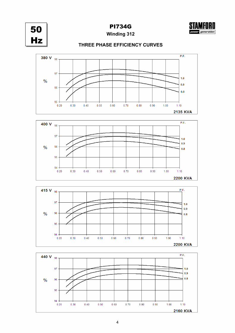
Winding 312PI734G
THREE PHASE EFFICIENCY CURVES
50Hz
4

Winding 312PI734G
THREE PHASE EFFICIENCY CURVES
60Hz
5

PI734GWinding 312
Locked Rotor Motor Starting Curve
0
5
10
15
20
25
30
0 500 1000 1500 2000 2500 3000 3500 4000LOCKED ROTOR kVA
PE
R C
EN
T T
RA
NS
IEN
T V
OL
TA
GE
DIP
.
380V 416V 440V 460V 480V
0
5
10
15
20
25
30
0 500 1000 1500 2000 2500 3000 3500 4000LOCKED ROTOR kVA
PE
R C
EN
T T
RA
NS
IEN
T V
OL
TA
GE
DIP
.
346V 380V 400V 415V 440V
60Hz
50Hz
6
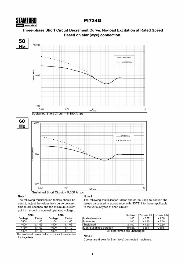
3-phase 2-phase L-L 1-phase L-NVoltage Factor Voltage Factor x 1.00 x 0.87 x 1.30
380v x 1.00 416v x 1.00 x 1.00 x 1.80 x 3.20400v x 1.05 440v x 1.06 x 1.00 x 1.50 x 2.50415v x 1.09 460v x 1.10 10 sec. 5 sec. 2 sec.440v x 1.16 480v x 1.15
PI734G
The sustained current value is constant irrespectiveof voltage level
Three-phase Short Circuit Decrement Curve. No-load Excitation at Rated SpeedBased on star (wye) connection.
Max. sustained durationAll other times are unchanged
Instantaneous
SustainedMinimum
50Hz 60Hz
Sustained Short Circuit = 8,150 Amps
Sustained Short Circuit = 9,500 AmpsNote 1The following multiplication factors should beused to adjust the values from curve betweentime 0.001 seconds and the minimum currentpoint in respect of nominal operating voltage :
Note 2The following multiplication factor should be used to convert thevalues calculated in accordance with NOTE 1 to those applicableto the various types of short circuit :
Note 3Curves are drawn for Star (Wye) connected machines.
50Hz
60Hz
1000
10000
100000
0.001 0.01 0.1 1 10TIME (secs)
CU
RR
EN
T (A
mps
)
SYMMETRICAL
ASYMMETRICAL
1000
10000
100000
0.001 0.01 0.1 1 10TIME (secs)
CU
RR
EN
T (A
mps
)
SYMMETRICAL
ASYMMETRICAL
7

Class - Temp Rise
Star (V) 380 400 415 440 380 400 415 440 380 400 415 440 380 400 415 440
kVA 1985 2050 2050 2005 2135 2200 2200 2160 2225 2295 2295 2250 2290 2360 2360 2310
kW 1588 1640 1640 1604 1708 1760 1760 1728 1780 1836 1836 1800 1832 1888 1888 1848
Efficiency (%) 96.1 96.2 96.3 96.4 96.0 96.0 96.1 96.3 95.9 95.9 96.0 96.2 95.8 95.9 96.0 96.1
kW Input 1652 1705 1703 1664 1779 1833 1831 1794 1856 1914 1913 1871 1912 1969 1967 1923
Star (V) 416 440 460 480 416 440 460 480 416 440 460 480 416 440 460 480
kVA 2305 2455 2510 2560 2475 2640 2695 2750 2575 2750 2805 2860 2650 2825 2885 2945
kW 1844 1964 2008 2048 1980 2112 2156 2200 2060 2200 2244 2288 2120 2260 2308 2356
Efficiency (%) 96.0 96.1 96.1 96.2 95.9 95.9 96.0 96.1 95.8 95.8 95.9 96.0 95.7 95.7 95.8 95.9
kW Input 1921 2044 2089 2129 2065 2202 2246 2289 2150 2296 2340 2383 2215 2362 2409 2457
TD_PI734G.GB_05.04_02_GB
DIMENSIONS
PI734G
Cont. F - 105/40°C Cont. H - 125/40°C Standby - 150/40°C Standby - 163/27°C
Winding 312 / 0.8 Power Factor
RATINGS
50Hz
60Hz
Barnack Road • Stamford • Lincolnshire • PE9 2NBTel: 00 44 (0)1780 484000 • Fax: 00 44 (0)1780 484100
Website: www.newage-avkseg.com© 2004 Newage International Limited.Reprinted with permission of N.I. only.Printed in England.

New InteliGen NT
GENERAL PURPOSE COMPACT GEN–SET CONTROLLER
LEADER IN GEN–SETCOMMUNICATION SOLUTION
ComAp is a member of AMPS(The Association of Manufacturers of Power generating Systems).
ComAp products meet the highest standards, with every stage of production undertaken in accordance with the ISO certification obtained in 1998.
Description
New Technology InteliGen is a
comprehensive controller for both
single and multiple gen-sets operating
in standby or parallel modes. Compact
construction is optimized for these
purposes; various HW modifications
allow the customer to select the
optimum type for a particular application.
Built-in synchronizer and digital
isochronous load sharer allow total
integrated solution for gen-sets in
standby, island parallel or mains parallel.
Native cooperation of up to 32 gen-sets
is a standard feature.
InteliGenNT supports many standard ECU
types and is especially designed to easily
integrate new ones.
Powerful graphic display with user-friendly
control allows even new users to find
quickly the required information.
ComAp is open to various customized
firmware solutions.
Benefits Support of engines with ECU
(Electronic Control Unit)
Excellent configurability allows
matching exactly the customer’s
needs
Complete integrated gen-set solution
and signal sharing via CAN bus
– minimum external components
needed
Many communication options – easy
remote supervising and servicing
Perfect price/performance ratio
Gen-set performance log for easy
problem tracing

New InteliGen NT
GENERAL PURPOSE COMPACT GEN–SET CONTROLLER
InteliGenNT
Support of engines with ECU (J1939, ModBus and other proprietary interfaces); alarm codes displayed in text form
AMF function
Automatic synchronizing and power control (via speed governor or ECU)
Baseload, Import/Export
Peak shaving
Voltage and PF control (AVR)
Generator measurement: U, I, Hz, kW, kVAr, kVA, PF, kWh, kVAhr
Mains measurement: U, I, Hz, kW, kVAr, PF
Inputs and outputs configurable for various customer needs
RS232/RS485 interface with ModBus support; Analog/GSM/ISDN/CDMA modem support; SMS messages; ECU ModBus interface
Event-based history (up to 500 records) with customer-selectable list of stored values; RTC; statistic values
Integrated PLC programmable functions
Interface to remote display unit (IG-Display)
Dimensions 180x120 mm (front panel)
Sealed to IP65
InteliGenNTC
All items from InteliGenNT Features list
+ Selectable measurement ranges for AC voltages and currents – 120 / 277 V, 0-1 / 0-5 A
+ Secondary RS232/RS485 interface with the same features as the primary one; additionally, the RS485 converter is isolated
+ USB 2.0 slave interface
Integrated fixed and configurable protections 3 phase integrated generator protections
(U + f)
IDMT overcurrent + Shortcurrent
protection
Overload protection
Reverse power protection
Earth fault protection
3 phase integrated mains protections
(U + f)
Vector shift protection
All binary/analogue inputs free
configurable for various protection
types: HistRecOnly / Alarm Only /
Warning / Off load / Slow stop /
BreakerOpen&Cooldown / Shutdown /
Mains protect / Sensor fail
Additional 160 programmable protections
configurable for any measured value to
create customer-specific protections
Features
PC
PC
IG-DISPLAY
MODEMPC MODEM
IS-BIN16/8
�������
I-CB/XX
IGS-PTM
IGL-RA15
I-CB/XX
IGS-PTM
IGL-RA15
I-AOUT8
I-CB/XXI-CB/XXI-CB/XX
IS-BIN16/8
�������
IS-BIN16/8
��������������
ENGINE
12 BINARY
OUTPUTS
(OPEN
COLLECTOR)
3 ANALOG
INPUTS
GENERATOR
MAINSIG-NT/IG-NTC
EARTH FAULT
CURRENT
CURRENTVO
LTAGE
SG O
UT
AVRi OUT
INTER-CONTROLLER
& MONITORING
CAN2
RS 232(1)
INTERFACERS485(1)IG-DISPLAY
or CONVERTER
forRS232(1)
RS232/RS485(2)
INTERFACE
(IG-NTC only)
USB 12 BINARY INPUTS
EXTENSION
MODULES
CAN1
POWER SUPPLY
8 TO 36 VDC+ -
CURRENTVO
LTAGE
MEASUREM
ENT
12
3
GENERATOR
DIESEL/GAS ENGINE
Starter
Fuel Solenoid
LOAD
1ph3ph3ph
Generator C. B. Control
1ph3ph
Mains C. B. Control
MAINS
10
IGS-NT-LSM+PMS dongle:
POWER MANAGEMENT
DIGITAL LOAD SHARING
DIGITAL VAr SHARING
Protocol depends on ECU type
CAN J1939
Proprietary
ECU coms.
(MDEC/M
TU,
CCM/CAT, ...)
Proprietary ECU coms.
(MODBUS/CUMMINS, ...)
IG-IB
I-LB
IG-IB
21
3
3
21 ECU
SPEED GOVERNOR AVR
AVRi
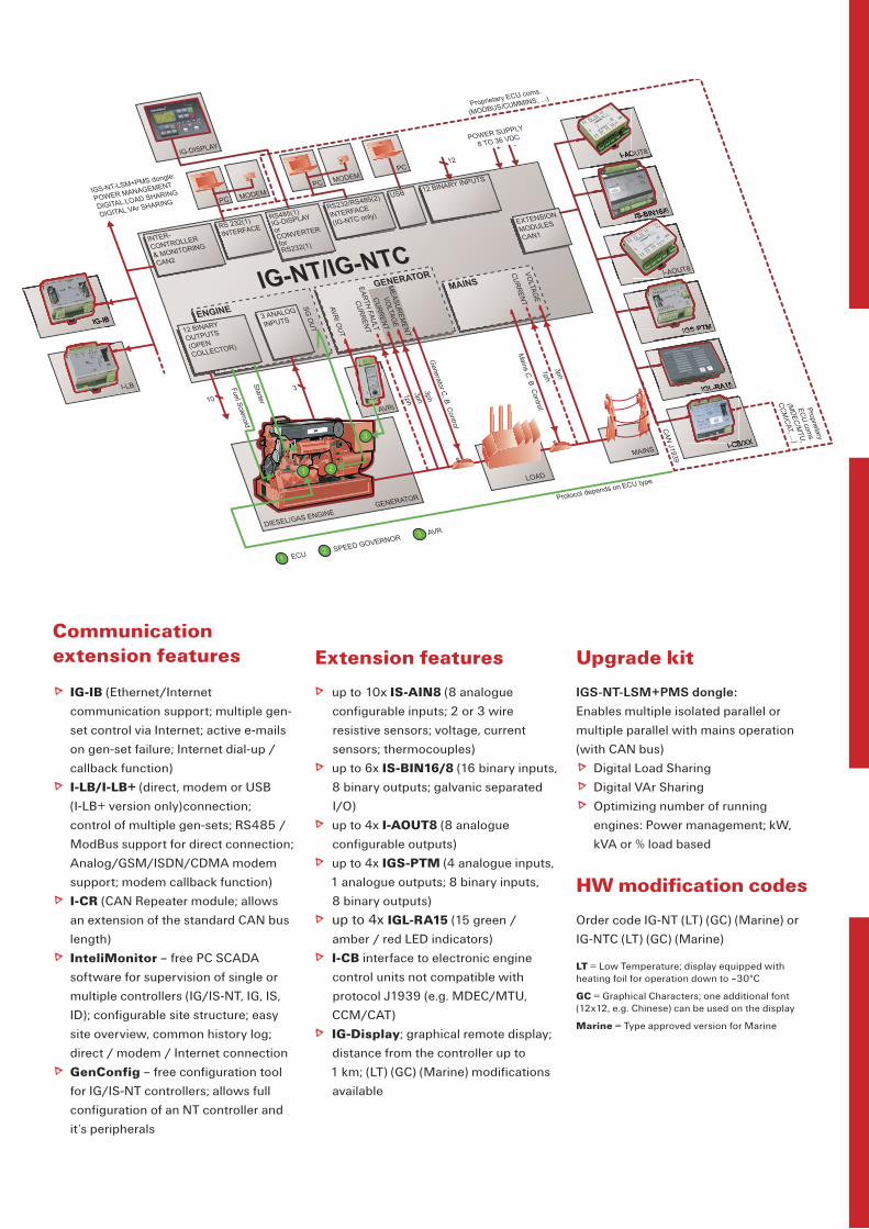
Extension features
up to 10x IS-AIN8 (8 analogue
configurable inputs; 2 or 3 wire
resistive sensors; voltage, current
sensors; thermocouples)
up to 6x IS-BIN16/8 (16 binary inputs,
8 binary outputs; galvanic separated
I/O)
up to 4x I-AOUT8 (8 analogue
configurable outputs)
up to 4x IGS-PTM (4 analogue inputs,
1 analogue outputs; 8 binary inputs,
8 binary outputs)
up to 4x IGL-RA15 (15 green /
amber / red LED indicators)
I-CB interface to electronic engine
control units not compatible with
protocol J1939 (e.g. MDEC/MTU,
CCM/CAT)
IG-Display; graphical remote display;
distance from the controller up to
1 km; (LT) (GC) (Marine) modifications
available
Communicationextension features
IG-IB (Ethernet/Internet
communication support; multiple gen-
set control via Internet; active e-mails
on gen-set failure; Internet dial-up /
callback function)
I-LB/I-LB+ (direct, modem or USB
(I-LB+ version only)connection;
control of multiple gen-sets; RS485 /
ModBus support for direct connection;
Analog/GSM/ISDN/CDMA modem
support; modem callback function)
I-CR (CAN Repeater module; allows
an extension of the standard CAN bus
length)
InteliMonitor – free PC SCADA
software for supervision of single or
multiple controllers (IG/IS-NT, IG, IS,
ID); configurable site structure; easy
site overview, common history log;
direct / modem / Internet connection
GenConfig – free configuration tool
for IG/IS-NT controllers; allows full
configuration of an NT controller and
it‘s peripherals
Upgrade kit
IGS-NT-LSM+PMS dongle:
Enables multiple isolated parallel or
multiple parallel with mains operation
(with CAN bus)
Digital Load Sharing
Digital VAr Sharing
Optimizing number of running
engines: Power management; kW,
kVA or % load based
HW modification codes
Order code IG-NT (LT) (GC) (Marine) or
IG-NTC (LT) (GC) (Marine)
LT = Low Temperature; display equipped with heating foil for operation down to –30°C
GC = Graphical Characters; one additional font (12x12, e.g. Chinese) can be used on the display
Marine = Type approved version for Marine

Features and specification are subject to change without prior notice 2005-11
BASIC TYPE TABLE
BINARY INPUTS
BINARY OUTPUTS
ANALOG INPUTS
ANALOG OUTPUTS
COMMUNICATIONPORTS
AC MEASUREMENT RANGES
(GEN., MAINS/BUS)
REMOTEDISPLAYS
INTEGRATEDPLC
IG-EE 6 6 — —1x RS232/
RS485277 V, 0-5 A 1x IG-Display standard
IG-EEC 6 6 — —2x RS232/
RS485, USB120 / 277 V, 0-1 / 0-5 A
1x IG-Display standard
IG-NT 12 12 3 —1x RS232/
RS485277 V, 0-5 A 1x IG-Display standard
IG-NTC 12 12 3 —2x RS232/
RS485, USB120 / 277 V, 0-1 / 0-5 A
1x IG-Display standard
IS-NT-BB 16 16 4 12x RS232/
RS485, USB120 / 277 V, 0-1 / 0-5 A
up to 3x IS-Display
extended
IM-NT 6 6 — —1x RS232/
RS485120 / 277,0-1 / 0-5 A
1x IG-Display extended
ComAp, spol. s r. o.Czech RepublicPhone: + 420 266 790 611 Fax: + 420 266 316 647E-mail: [email protected]: www.comap.cz
MANUFACTURER: LOCAL DISTRIBUTOR / PARTNER:
InteliGen® is a comprehensive controller for both single and
multiple gen-sets operating in standby or parallel modes.
InteliSys® is an expandable controller for both single and
multiple gen-sets operating in standby or parallel modes,
especially in CHP and other complex applications.
www.comap.czFor more information about our products and solutions visit our web-page
NEW TECHNOLOGY RANGE OF CONTROLLERS