Model OI-7530 The Relayer · Relayer OI-7530. This document should be read before initial operation...
30
Model OI-7530 The Relayer _____________________________________________________ Operation Manual Revision 2.1w _____________________________________________________________________________________________________________________________ _____________________________________________________________________________________________________________________________
Transcript of Model OI-7530 The Relayer · Relayer OI-7530. This document should be read before initial operation...

Model OI-7530The Relayer
_____________________________________________________
Operation ManualRevision 2.1w
_____________________________________________________________________________________________________________________________
_____________________________________________________________________________________________________________________________

Product Overview
The GenII WireFree Relayer OI-7530 is a 32-channel 3-relay wireless relay/alarm system specifically designed for use in conjunction with Otis Instruments, Inc. GenII WireFree Sensor Assemblies.
The OI-7530 can monitor up to 32 sensors. The ability to mount the device near the entrance of a site allows the technician to immediately determine if it is safe to enter the site, making this device incredibly useful in any environment hosting hazardous gas. The OI-7530 can be mounted as a traditional or self-contained system that requires 12-24 Volts DC or 120/240 Volts AC. The OI-7530 receives transmissions from WireFree sensors via an on-board 900MHz (expected release 1H 2011) or 2.4GHz GenII radio.
These key features—and more—make the OI-7530 a reliable and convenient tool that is incredibly useful in any environment hosting hazardous gas.
2
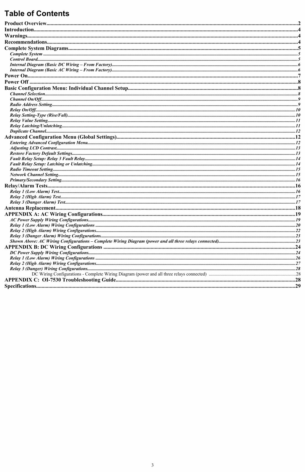
Table of ContentsProduct Overview..........................................................................................................................................................................................2Introduction...................................................................................................................................................................................................4Warnings........................................................................................................................................................................................................4Recommendations..........................................................................................................................................................................................4Complete System Diagrams..........................................................................................................................................................................5
Complete System ............................................................................................................................................................................................................................5Control Board.................................................................................................................................................................................................................................5Internal Diagram (Basic DC Wiring – From Factory)................................................................................................................................................................6Internal Diagram (Basic AC Wiring – From Factory).................................................................................................................................................................6
Power On........................................................................................................................................................................................................7Power Off .......................................................................................................................................................................................................8Basic Configuration Menu: Individual Channel Setup..............................................................................................................................8
Channel Selection..........................................................................................................................................................................................................................8Channel On/Off..............................................................................................................................................................................................................................9Radio Address Setting....................................................................................................................................................................................................................9Relay On/Off.................................................................................................................................................................................................................................10Relay Setting-Type (Rise/Fall).....................................................................................................................................................................................................10Relay Value Setting......................................................................................................................................................................................................................11Relay Latching/Unlatching..........................................................................................................................................................................................................11Duplicate Channel........................................................................................................................................................................................................................12
Advanced Configuration Menu (Global Settings)....................................................................................................................................12Entering Advanced Configuration Menu....................................................................................................................................................................................12Adjusting LCD Contrast...............................................................................................................................................................................................................13Restore Factory Default Settings.................................................................................................................................................................................................13Fault Relay Setup: Relay 3 Fault Relay......................................................................................................................................................................................14Fault Relay Setup: Latching or Unlatching................................................................................................................................................................................14Radio Timeout Setting..................................................................................................................................................................................................................15Network Channel Setting.............................................................................................................................................................................................................15Primary/Secondary Setting..........................................................................................................................................................................................................16
Relay/Alarm Tests.......................................................................................................................................................................................16Relay 1 (Low Alarm) Test............................................................................................................................................................................................................16Relay 2 (High Alarm) Test...........................................................................................................................................................................................................17Relay 3 (Danger Alarm) Test.......................................................................................................................................................................................................17
Antenna Replacement.................................................................................................................................................................................18APPENDIX A: AC Wiring Configurations...............................................................................................................................................19
AC Power Supply Wiring Configurations...................................................................................................................................................................................19Relay 1 (Low Alarm) Wiring Configurations .............................................................................................................................................................................20Relay 2 (High Alarm) Wiring Configurations............................................................................................................................................................................22Relay 3 (Danger Alarm) Wiring Configurations........................................................................................................................................................................23Shown Above: AC Wiring Configurations – Complete Wiring Diagram (power and all three relays connected)..................................................................23
APPENDIX B: DC Wiring Configurations ..............................................................................................................................................24DC Power Supply Wiring Configurations...................................................................................................................................................................................24Relay 1 (Low Alarm) Wiring Configurations .............................................................................................................................................................................26Relay 2 (High Alarm) Wiring Configurations............................................................................................................................................................................27Relay 3 (Danger) Wiring Configurations....................................................................................................................................................................................28
DC Wiring Configurations - Complete Wiring Diagram (power and all three relays connected) ...........................................................................28APPENDIX C: OI-7530 Troubleshooting Guide.....................................................................................................................................28Specifications................................................................................................................................................................................................29
3
Introduction
This document is an Operation Manual containing diagrams and step-by-step instruction for proper operation of the Otis Instruments, Inc. GenII WireFree Relayer OI-7530. This document should be read before initial operation of the product.
Should a question arise during the use of the product, this document will serve as a first reference for consultation. If further questions arise, or if the device is not working properly, please contact the sales representative of this product.
Warnings
To ensure technician safety, always wire the relays before supplying power to the device.
Do not open the enclosure while the area is classified as Class I Division 1.
Do not open the enclosure if an explosive gas atmosphere may be present.
The Otis Instruments GenII WireFree Relayer OI-7530 enclosure is Class I Division 1 Certified. However, if the Adalet lid is removed, for whatever reason, the OI-7530 certification is not valid.
Recommendations
For optimal performance, the manufacturer recommends using a minimum of 22 gauge wire for all Wiring Configurations.
Different loads require different gauge wire. Use the appropriate wire size—depending on the voltage and current requirements.
4
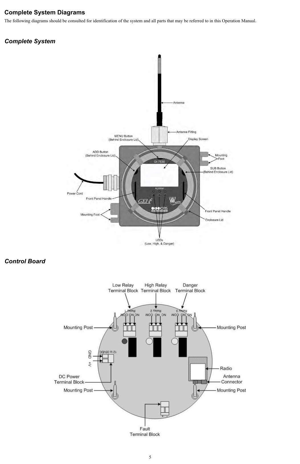
Complete System DiagramsThe following diagrams should be consulted for identification of the system and all parts that may be referred to in this Operation Manual.
Complete System
Control Board
5
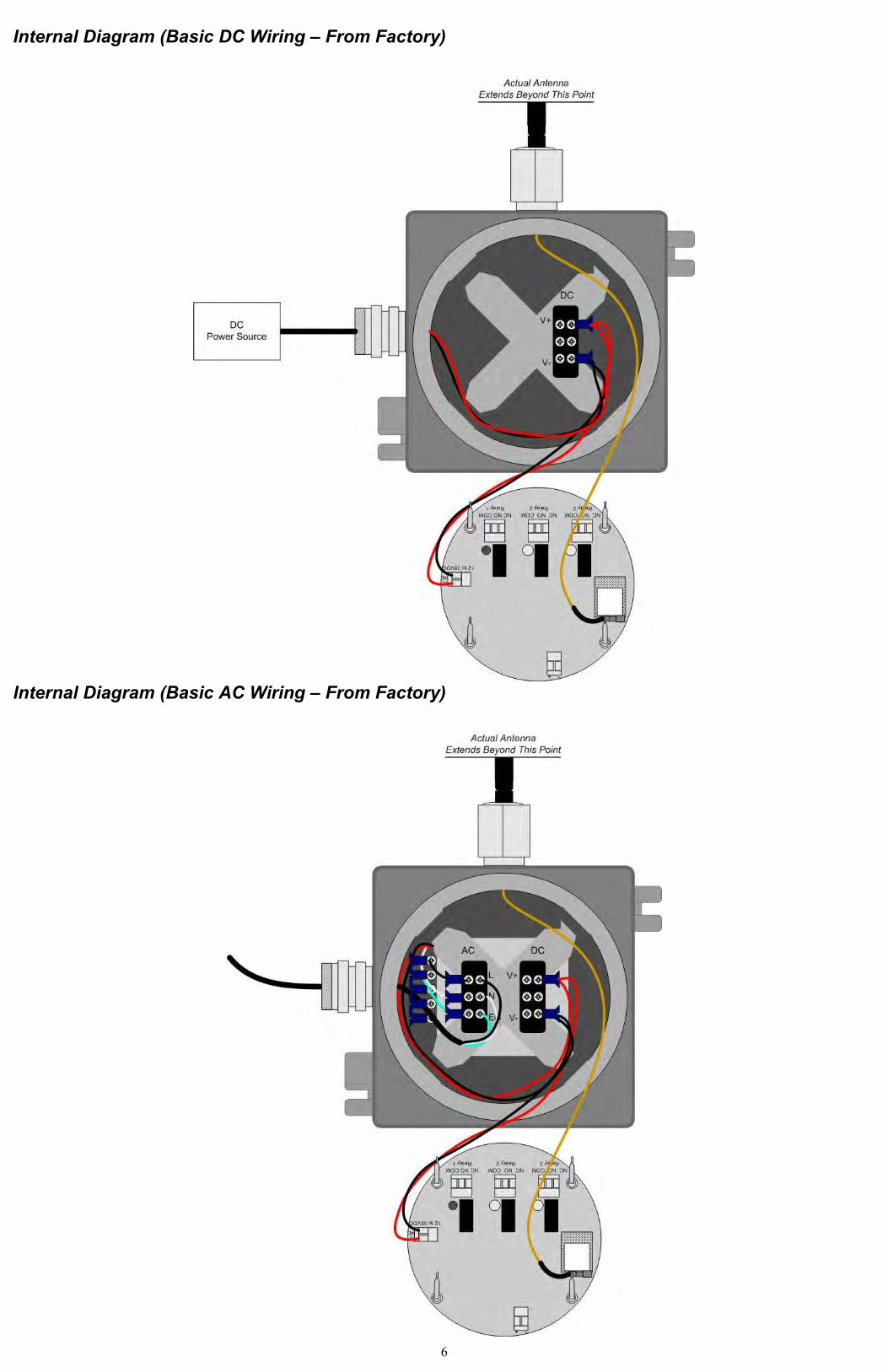
Internal Diagram (Basic DC Wiring – From Factory)
Internal Diagram (Basic AC Wiring – From Factory)
6
Power OnPowering on the device activates its functions. When powered on, the device is fully functional and access to system and settings menus is allowed.
NOTE: Do not open the enclosure while the area is classified as Class I Division 1, or if an explosive gas atmosphere may be present.
1. The OI-7530 will automatically Power On when the Power Wiring Configurations are complete and voltage is supplied to the unit.
2. The device will then count down from 10 to 0.
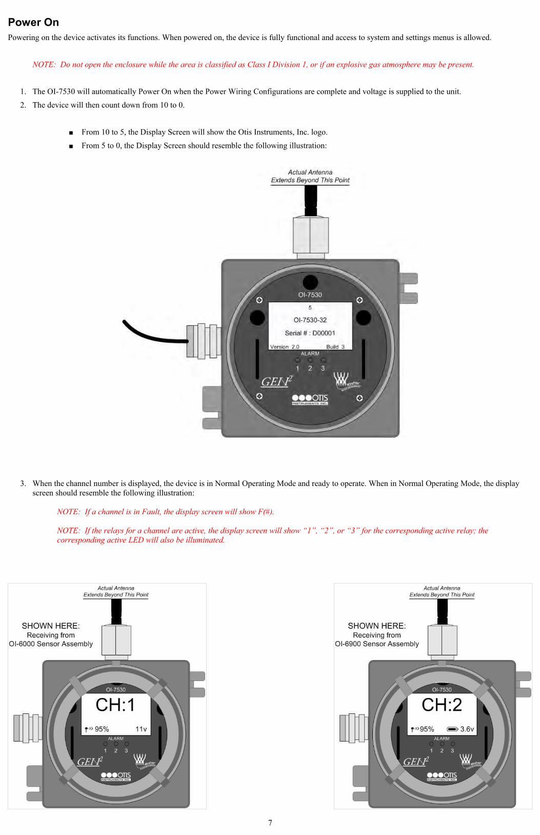
From 10 to 5, the Display Screen will show the Otis Instruments, Inc. logo.
From 5 to 0, the Display Screen should resemble the following illustration:
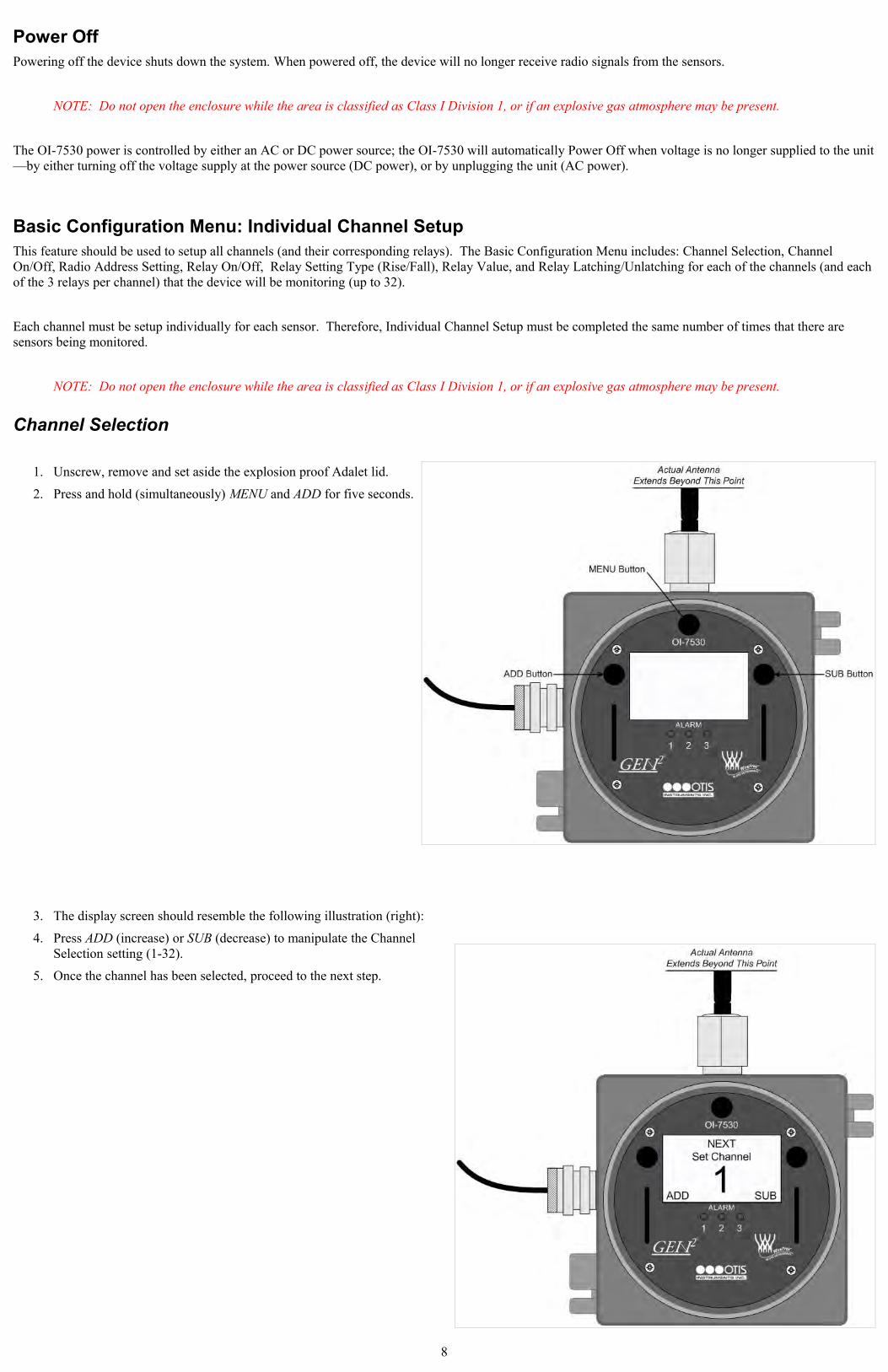
3. When the channel number is displayed, the device is in Normal Operating Mode and ready to operate. When in Normal Operating Mode, the display screen should resemble the following illustration:
NOTE: If a channel is in Fault, the display screen will show F(#).
NOTE: If the relays for a channel are active, the display screen will show “1”, “2”, or “3” for the corresponding active relay; the corresponding active LED will also be illuminated.
7
Power Off Powering off the device shuts down the system. When powered off, the device will no longer receive radio signals from the sensors.
NOTE: Do not open the enclosure while the area is classified as Class I Division 1, or if an explosive gas atmosphere may be present.
The OI-7530 power is controlled by either an AC or DC power source; the OI-7530 will automatically Power Off when voltage is no longer supplied to the unit—by either turning off the voltage supply at the power source (DC power), or by unplugging the unit (AC power).
Basic Configuration Menu: Individual Channel SetupThis feature should be used to setup all channels (and their corresponding relays). The Basic Configuration Menu includes: Channel Selection, Channel On/Off, Radio Address Setting, Relay On/Off, Relay Setting Type (Rise/Fall), Relay Value, and Relay Latching/Unlatching for each of the channels (and each of the 3 relays per channel) that the device will be monitoring (up to 32).
Each channel must be setup individually for each sensor. Therefore, Individual Channel Setup must be completed the same number of times that there are sensors being monitored.
NOTE: Do not open the enclosure while the area is classified as Class I Division 1, or if an explosive gas atmosphere may be present.
Channel Selection
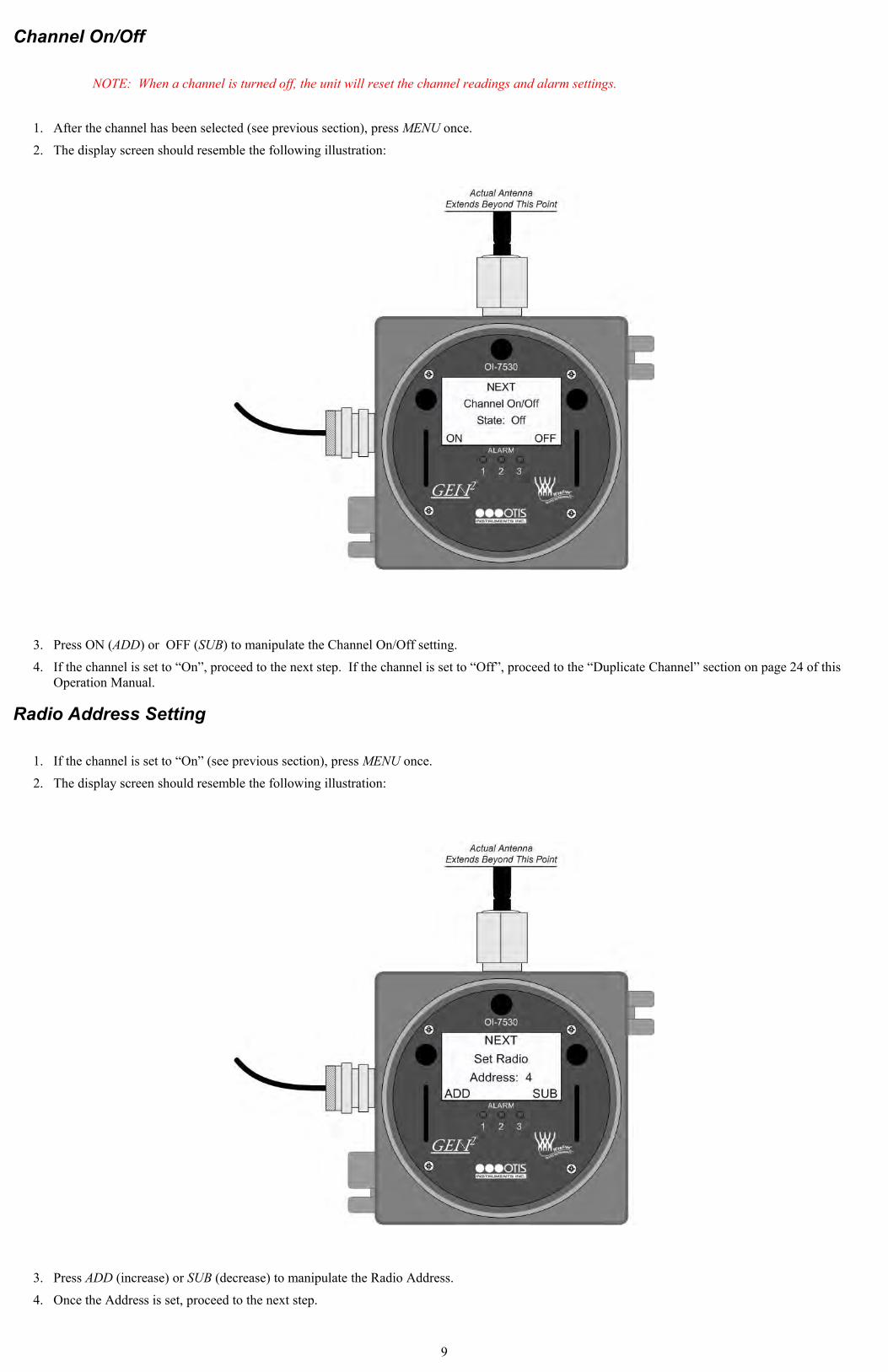
1. Unscrew, remove and set aside the explosion proof Adalet lid.
2. Press and hold (simultaneously) MENU and ADD for five seconds.
3. The display screen should resemble the following illustration (right):
4. Press ADD (increase) or SUB (decrease) to manipulate the Channel Selection setting (1-32).
5. Once the channel has been selected, proceed to the next step.
8
Channel On/Off
NOTE: When a channel is turned off, the unit will reset the channel readings and alarm settings.
1. After the channel has been selected (see previous section), press MENU once.
2. The display screen should resemble the following illustration:
3. Press ON (ADD) or OFF (SUB) to manipulate the Channel On/Off setting.
4. If the channel is set to “On”, proceed to the next step. If the channel is set to “Off”, proceed to the “Duplicate Channel” section on page 24 of this Operation Manual.
Radio Address Setting
1. If the channel is set to “On” (see previous section), press MENU once.
2. The display screen should resemble the following illustration:
3. Press ADD (increase) or SUB (decrease) to manipulate the Radio Address.
4. Once the Address is set, proceed to the next step.
9
Relay On/Off
1. After the address has been set (see previous section), press MENU once.
2. The display screen should resemble the following illustration:
3. Press ON (ADD) or OFF (SUB) to manipulate the Relay On/Off setting.
4. If the relay is set to “On”, proceed to the next step. If the relay is set to “Off”, proceed to the “Duplicate Channel” section on page 24 of this Operation Manual.
Relay Setting-Type (Rise/Fall)
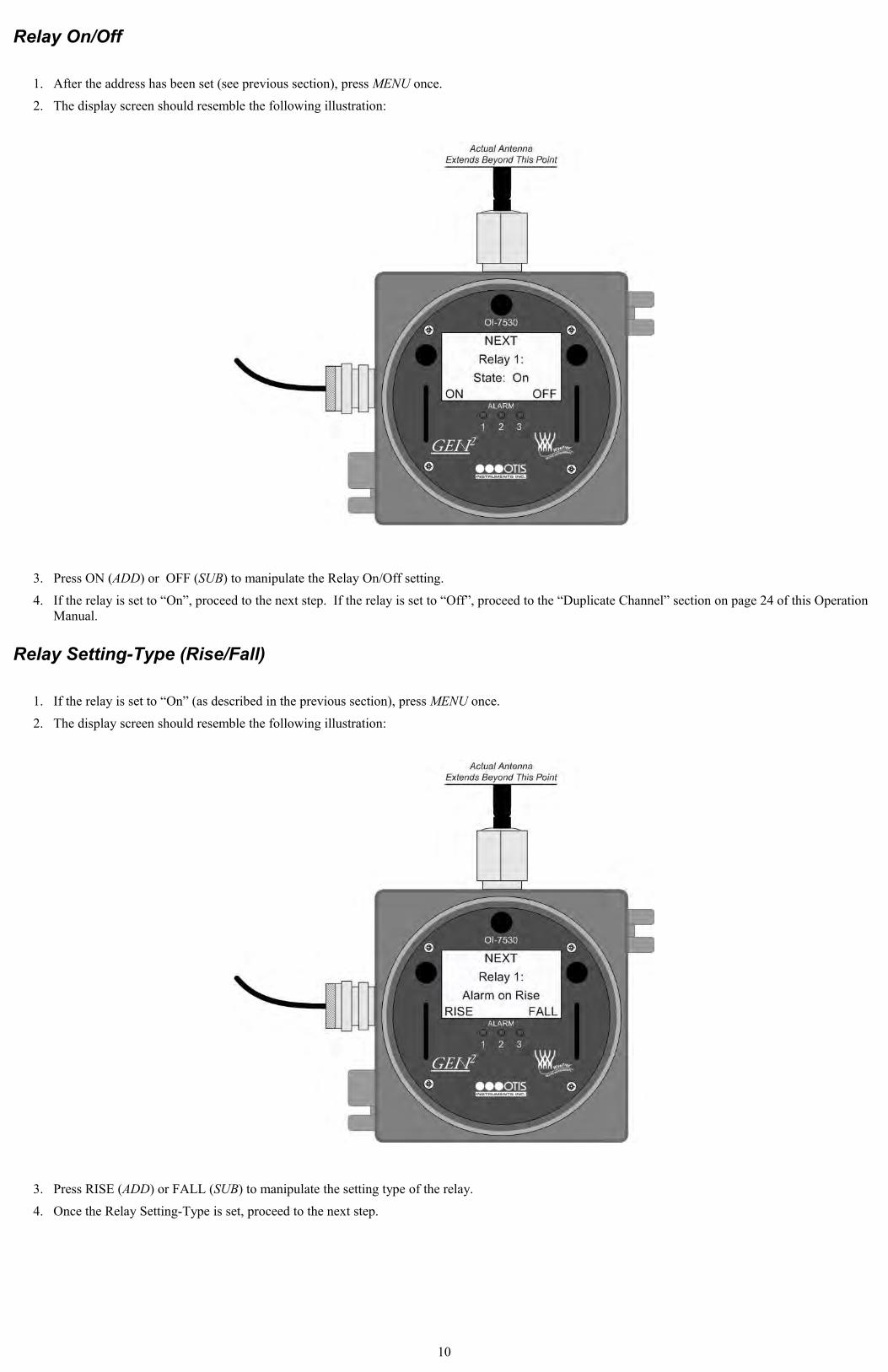
1. If the relay is set to “On” (as described in the previous section), press MENU once.
2. The display screen should resemble the following illustration:
3. Press RISE (ADD) or FALL (SUB) to manipulate the setting type of the relay.
4. Once the Relay Setting-Type is set, proceed to the next step.
10
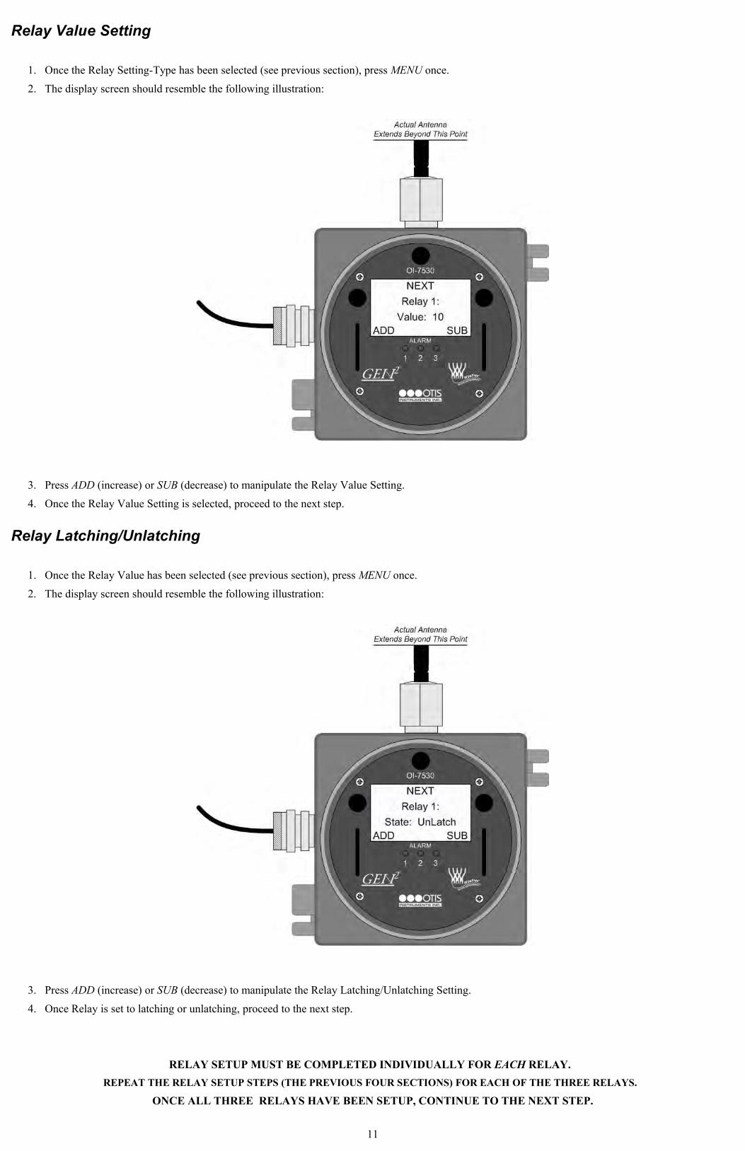
Relay Value Setting
1. Once the Relay Setting-Type has been selected (see previous section), press MENU once.
2. The display screen should resemble the following illustration:
3. Press ADD (increase) or SUB (decrease) to manipulate the Relay Value Setting.
4. Once the Relay Value Setting is selected, proceed to the next step.
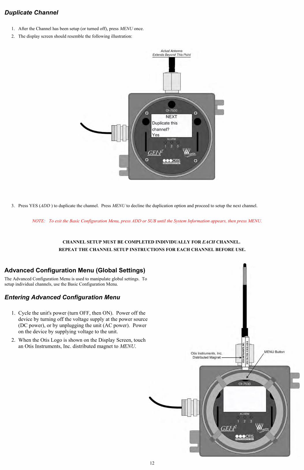
Relay Latching/Unlatching
1. Once the Relay Value has been selected (see previous section), press MENU once.
2. The display screen should resemble the following illustration:
3. Press ADD (increase) or SUB (decrease) to manipulate the Relay Latching/Unlatching Setting.
4. Once Relay is set to latching or unlatching, proceed to the next step.
RELAY SETUP MUST BE COMPLETED INDIVIDUALLY FOR EACH RELAY. REPEAT THE RELAY SETUP STEPS (THE PREVIOUS FOUR SECTIONS) FOR EACH OF THE THREE RELAYS.
ONCE ALL THREE RELAYS HAVE BEEN SETUP, CONTINUE TO THE NEXT STEP.
11
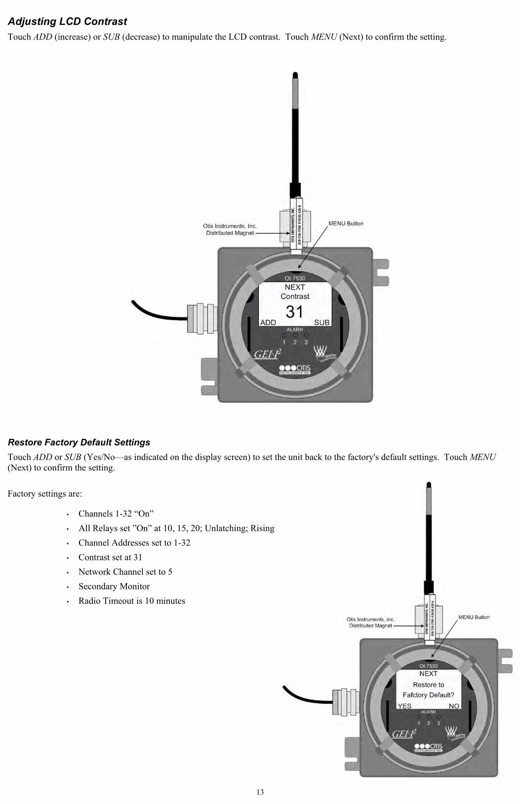
Duplicate Channel
1. After the Channel has been setup (or turned off), press MENU once.
2. The display screen should resemble the following illustration:
3. Press YES (ADD ) to duplicate the channel. Press MENU to decline the duplication option and proceed to setup the next channel.
NOTE: To exit the Basic Configuration Menu, press ADD or SUB until the System Information appears, then press MENU.
CHANNEL SETUP MUST BE COMPLETED INDIVIDUALLY FOR EACH CHANNEL. REPEAT THE CHANNEL SETUP INSTRUCTIONS FOR EACH CHANNEL BEFORE USE.
Advanced Configuration Menu (Global Settings)The Advanced Configuration Menu is used to manipulate global settings. To setup individual channels, use the Basic Configuration Menu.
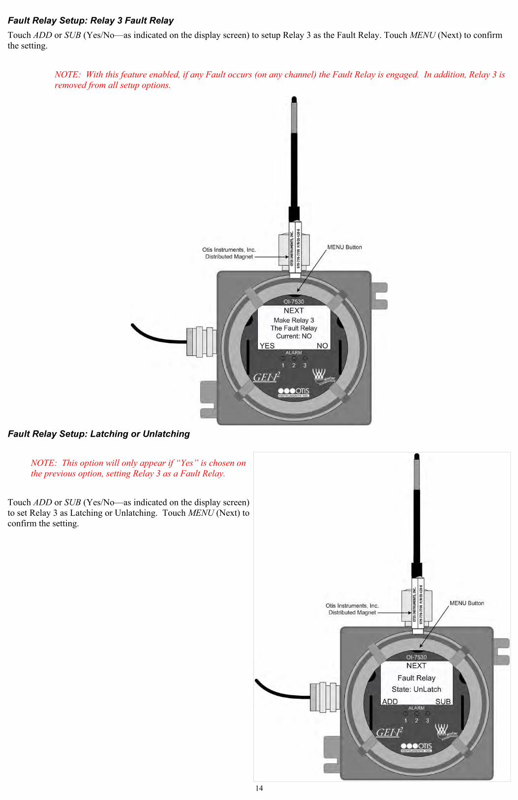
Entering Advanced Configuration Menu
1. Cycle the unit's power (turn OFF, then ON). Power off the device by turning off the voltage supply at the power source (DC power), or by unplugging the unit (AC power). Power on the device by supplying voltage to the unit.
2. When the Otis Logo is shown on the Display Screen, touch an Otis Instruments, Inc. distributed magnet to MENU.
12
Adjusting LCD ContrastTouch ADD (increase) or SUB (decrease) to manipulate the LCD contrast. Touch MENU (Next) to confirm the setting.
Restore Factory Default SettingsTouch ADD or SUB (Yes/No—as indicated on the display screen) to set the unit back to the factory's default settings. Touch MENU (Next) to confirm the setting.
Factory settings are:
• Channels 1-32 “On”• All Relays set ”On” at 10, 15, 20; Unlatching; Rising• Channel Addresses set to 1-32• Contrast set at 31• Network Channel set to 5• Secondary Monitor • Radio Timeout is 10 minutes
13
Fault Relay Setup: Relay 3 Fault RelayTouch ADD or SUB (Yes/No—as indicated on the display screen) to setup Relay 3 as the Fault Relay. Touch MENU (Next) to confirm the setting.
NOTE: With this feature enabled, if any Fault occurs (on any channel) the Fault Relay is engaged. In addition, Relay 3 is removed from all setup options.
Fault Relay Setup: Latching or Unlatching
NOTE: This option will only appear if “Yes” is chosen on the previous option, setting Relay 3 as a Fault Relay.
Touch ADD or SUB (Yes/No—as indicated on the display screen) to set Relay 3 as Latching or Unlatching. Touch MENU (Next) to confirm the setting.
14
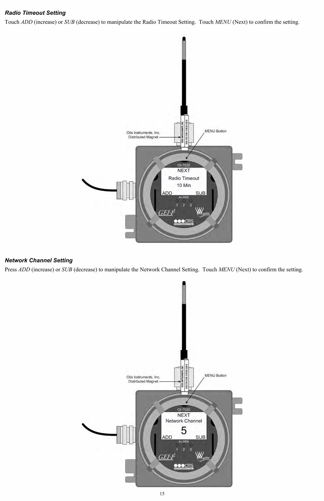
Radio Timeout SettingTouch ADD (increase) or SUB (decrease) to manipulate the Radio Timeout Setting. Touch MENU (Next) to confirm the setting.
Network Channel SettingPress ADD (increase) or SUB (decrease) to manipulate the Network Channel Setting. Touch MENU (Next) to confirm the setting.
15
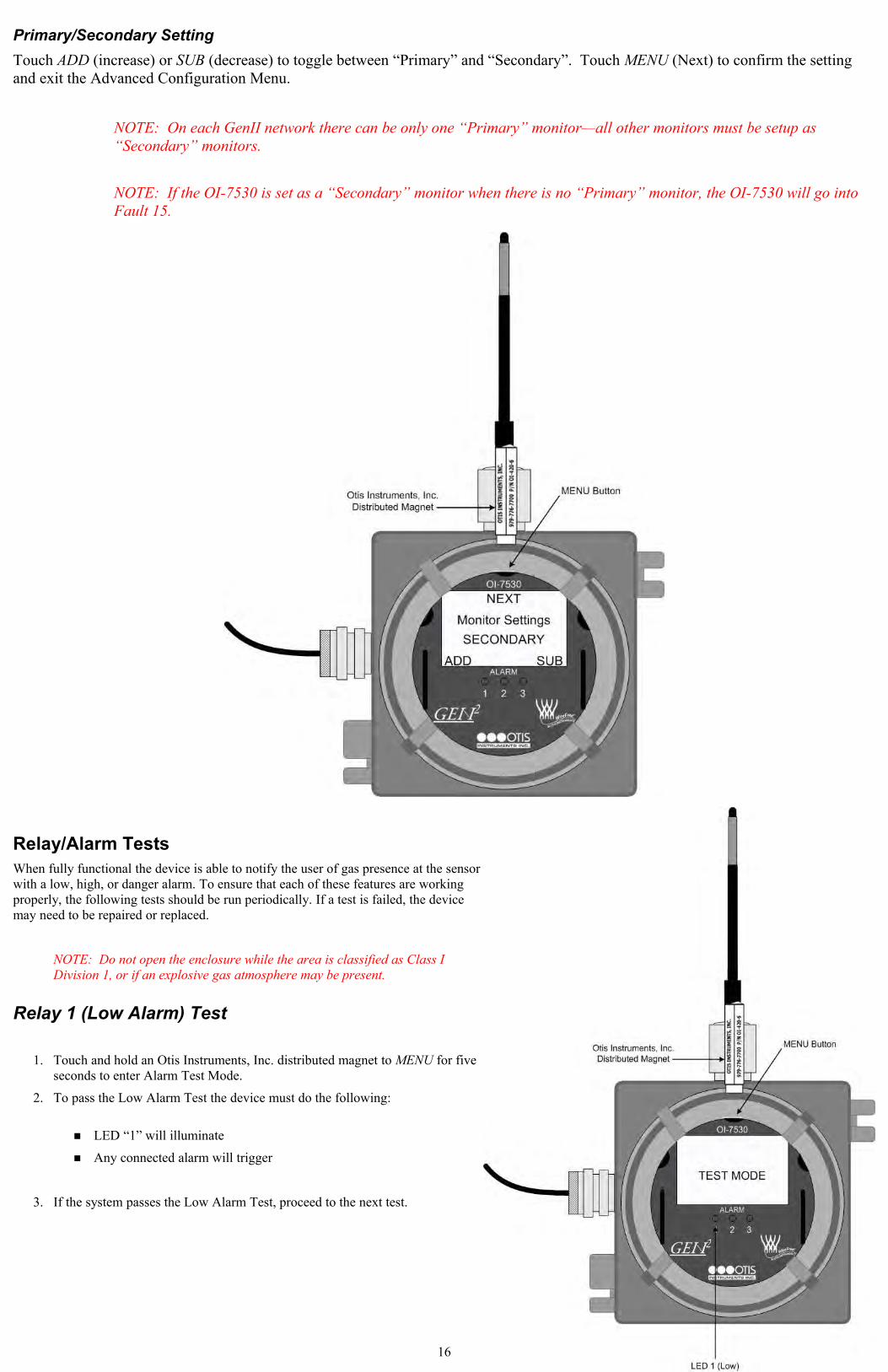
Primary/Secondary SettingTouch ADD (increase) or SUB (decrease) to toggle between “Primary” and “Secondary”. Touch MENU (Next) to confirm the setting and exit the Advanced Configuration Menu.
NOTE: On each GenII network there can be only one “Primary” monitor—all other monitors must be setup as “Secondary” monitors.
NOTE: If the OI-7530 is set as a “Secondary” monitor when there is no “Primary” monitor, the OI-7530 will go into Fault 15.
Relay/Alarm TestsWhen fully functional the device is able to notify the user of gas presence at the sensor with a low, high, or danger alarm. To ensure that each of these features are working properly, the following tests should be run periodically. If a test is failed, the device may need to be repaired or replaced.
NOTE: Do not open the enclosure while the area is classified as Class I Division 1, or if an explosive gas atmosphere may be present.
Relay 1 (Low Alarm) Test
1. Touch and hold an Otis Instruments, Inc. distributed magnet to MENU for five seconds to enter Alarm Test Mode.
2. To pass the Low Alarm Test the device must do the following:
■ LED “1” will illuminate
■ Any connected alarm will trigger
3. If the system passes the Low Alarm Test, proceed to the next test.
16
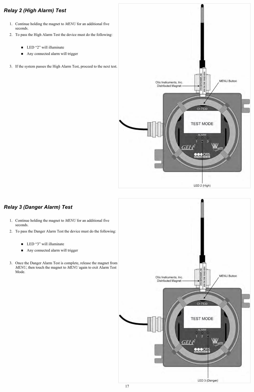
Relay 2 (High Alarm) Test
1. Continue holding the magnet to MENU for an additional five seconds.
2. To pass the High Alarm Test the device must do the following:
■ LED “2” will illuminate
■ Any connected alarm will trigger
3. If the system passes the High Alarm Test, proceed to the next test.
Relay 3 (Danger Alarm) Test
1. Continue holding the magnet to MENU for an additional five seconds.
2. To pass the Danger Alarm Test the device must do the following:
■ LED “3” will illuminate
■ Any connected alarm will trigger
3. Once the Danger Alarm Test is complete, release the magnet from MENU, then touch the magnet to MENU again to exit Alarm Test Mode.
17
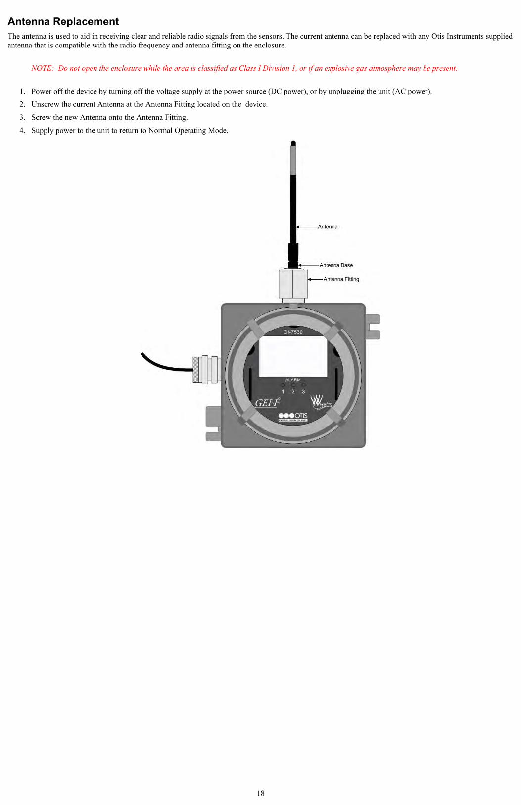
Antenna ReplacementThe antenna is used to aid in receiving clear and reliable radio signals from the sensors. The current antenna can be replaced with any Otis Instruments supplied antenna that is compatible with the radio frequency and antenna fitting on the enclosure.
NOTE: Do not open the enclosure while the area is classified as Class I Division 1, or if an explosive gas atmosphere may be present.
1. Power off the device by turning off the voltage supply at the power source (DC power), or by unplugging the unit (AC power).
2. Unscrew the current Antenna at the Antenna Fitting located on the device.
3. Screw the new Antenna onto the Antenna Fitting.
4. Supply power to the unit to return to Normal Operating Mode.
18
APPENDIX A: AC Wiring Configurations
AC Wiring ConfigurationsTo ensure full-functionality, complete ALL of the following Wiring Configurations before installing the device in the field. Please read all of the following items BEFORE wiring the device:
● The relay outputs are Dry Contacts. The following relay wiring configurations are one example of a common wiring scenario. Wiring choices for certain applications may differ from what is described in this Operation Manual.
● Verify that there is no power being sent from the power supply while wiring the relays.
● Otis Instruments, Inc. recommends wiring the relays as “NO” for most applications. With a “NO” relay, the relay will only be triggered if gas is seen.
● The user may choose to wire the relays as “NC” if desired. To do so, connect the neutral wire from the power supply to the terminal labeled “NC” (Normally Closed) instead of the terminal labeled “NO” (Normally Open).
● The wire colors used in the following drawings are used for ease of displaying which wires go where. Although the wire colors used in these drawings are standard colors, not all applications will use the same wire colors.
● To ensure technician safety, always wire the relays BEFORE supplying power to the device.
● For optimal performance, the manufacturer recommends using a minimum of 22 gauge wire for all Wiring Configurations. Different loads require different gauge wire. Use appropriate wire size, depending on the voltage and current requirements.
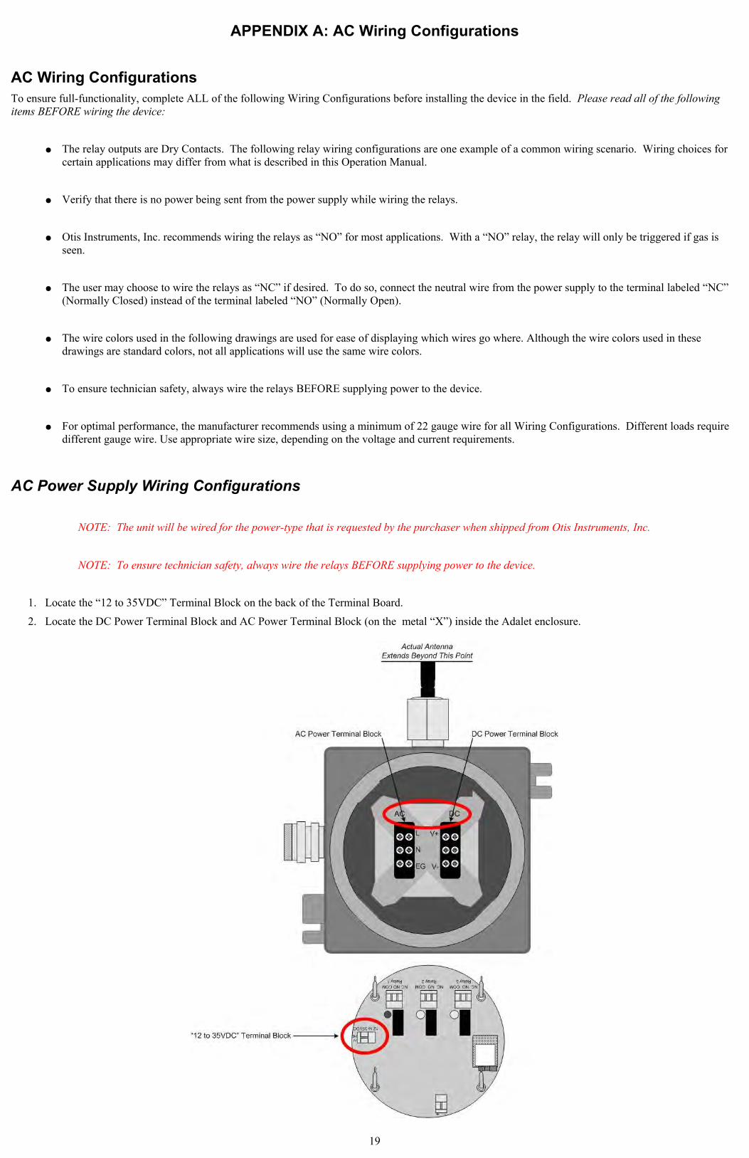
AC Power Supply Wiring Configurations
NOTE: The unit will be wired for the power-type that is requested by the purchaser when shipped from Otis Instruments, Inc.
NOTE: To ensure technician safety, always wire the relays BEFORE supplying power to the device.
1. Locate the “12 to 35VDC” Terminal Block on the back of the Terminal Board.
2. Locate the DC Power Terminal Block and AC Power Terminal Block (on the metal “X”) inside the Adalet enclosure.
19
AC Power Supply Wiring Configurations cont...
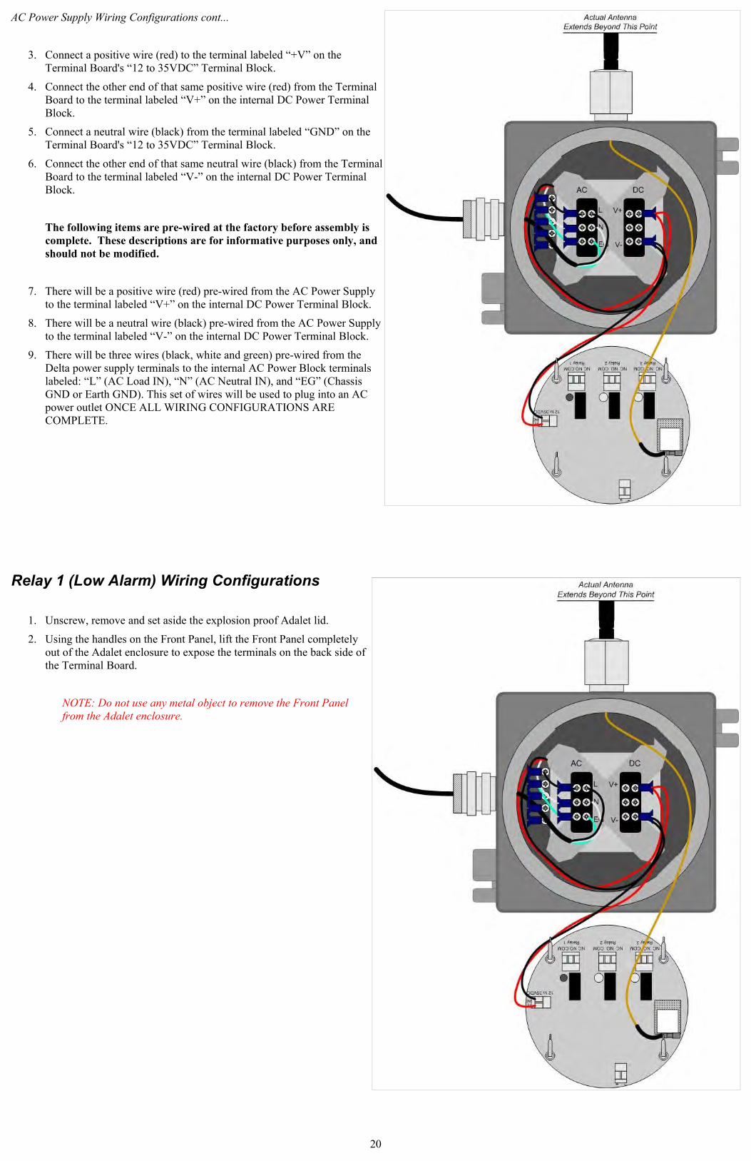
3. Connect a positive wire (red) to the terminal labeled “+V” on the Terminal Board's “12 to 35VDC” Terminal Block.
4. Connect the other end of that same positive wire (red) from the Terminal Board to the terminal labeled “V+” on the internal DC Power Terminal Block.
5. Connect a neutral wire (black) from the terminal labeled “GND” on the Terminal Board's “12 to 35VDC” Terminal Block.
6. Connect the other end of that same neutral wire (black) from the Terminal Board to the terminal labeled “V-” on the internal DC Power Terminal Block.
The following items are pre-wired at the factory before assembly is complete. These descriptions are for informative purposes only, and should not be modified.
7. There will be a positive wire (red) pre-wired from the AC Power Supply to the terminal labeled “V+” on the internal DC Power Terminal Block.
8. There will be a neutral wire (black) pre-wired from the AC Power Supply to the terminal labeled “V-” on the internal DC Power Terminal Block.
9. There will be three wires (black, white and green) pre-wired from the Delta power supply terminals to the internal AC Power Block terminals labeled: “L” (AC Load IN), “N” (AC Neutral IN), and “EG” (Chassis GND or Earth GND). This set of wires will be used to plug into an AC power outlet ONCE ALL WIRING CONFIGURATIONS ARE COMPLETE.
Relay 1 (Low Alarm) Wiring Configurations
1. Unscrew, remove and set aside the explosion proof Adalet lid.
2. Using the handles on the Front Panel, lift the Front Panel completely out of the Adalet enclosure to expose the terminals on the back side of the Terminal Board.
NOTE: Do not use any metal object to remove the Front Panel from the Adalet enclosure.
20
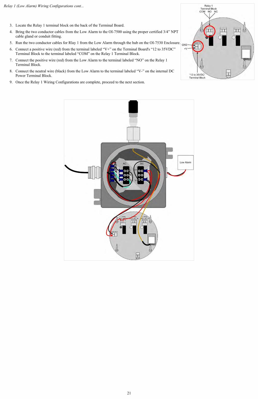
Relay 1 (Low Alarm) Wiring Configurations cont...
3. Locate the Relay 1 terminal block on the back of the Terminal Board.
4. Bring the two conductor cables from the Low Alarm to the OI-7500 using the proper certified 3/4” NPT cable gland or conduit fitting.
5. Run the two conductor cables for Rlay 1 from the Low Alarm through the hub on the OI-7530 Enclosure.
6. Connect a positive wire (red) from the terminal labeled “V+” on the Terminal Board's “12 to 35VDC” Terminal Block to the terminal labeled “COM” on the Relay 1 Terminal Block.
7. Connect the positive wire (red) from the Low Alarm to the terminal labeled “NO” on the Relay 1 Terminal Block.
8. Connect the neutral wire (black) from the Low Alarm to the terminal labeled “V-” on the internal DC Power Terminal Block.
9. Once the Relay 1 Wiring Configurations are complete, proceed to the next section.
21
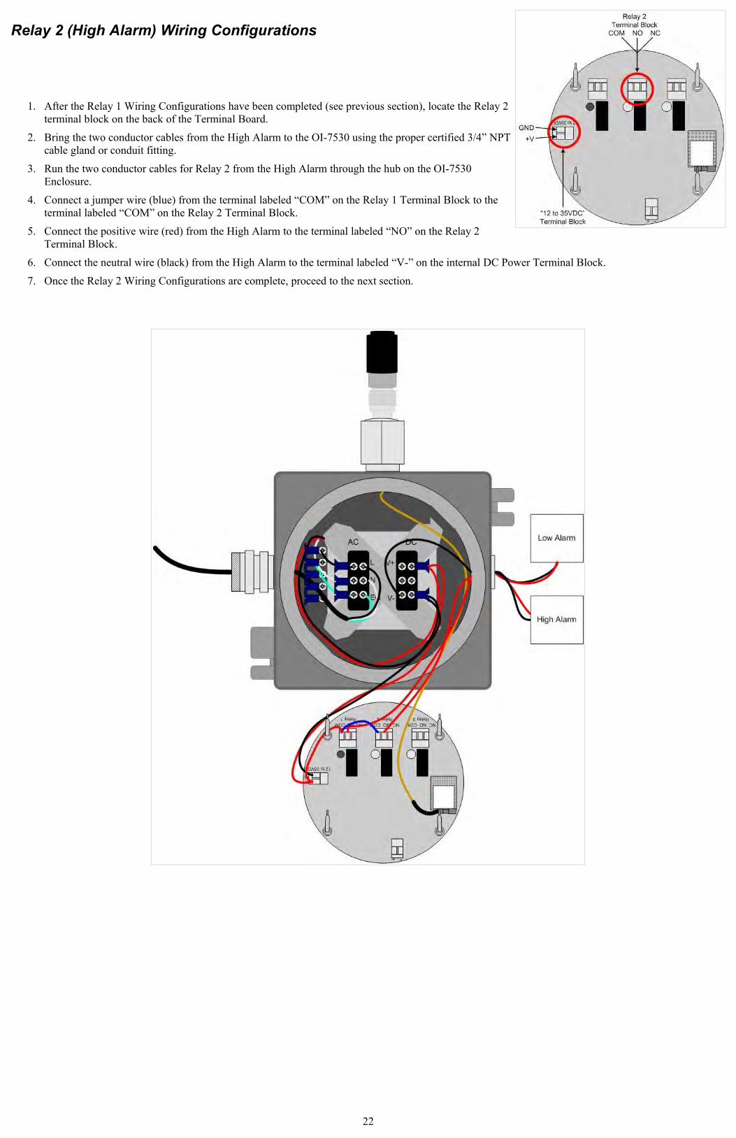
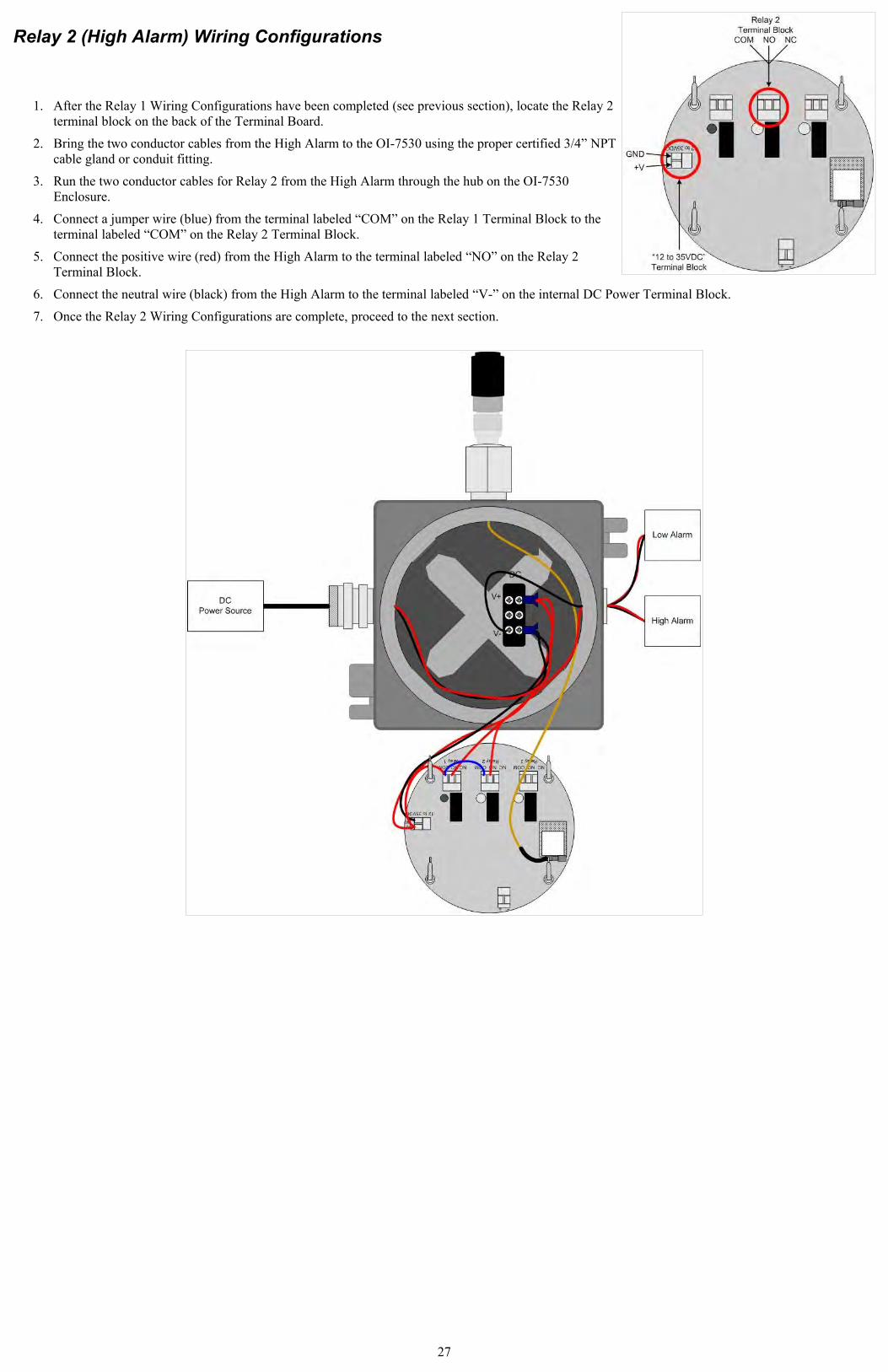
Relay 2 (High Alarm) Wiring Configurations
1. After the Relay 1 Wiring Configurations have been completed (see previous section), locate the Relay 2 terminal block on the back of the Terminal Board.
2. Bring the two conductor cables from the High Alarm to the OI-7530 using the proper certified 3/4” NPT cable gland or conduit fitting.
3. Run the two conductor cables for Relay 2 from the High Alarm through the hub on the OI-7530 Enclosure.
4. Connect a jumper wire (blue) from the terminal labeled “COM” on the Relay 1 Terminal Block to the terminal labeled “COM” on the Relay 2 Terminal Block.
5. Connect the positive wire (red) from the High Alarm to the terminal labeled “NO” on the Relay 2 Terminal Block.
6. Connect the neutral wire (black) from the High Alarm to the terminal labeled “V-” on the internal DC Power Terminal Block.
7. Once the Relay 2 Wiring Configurations are complete, proceed to the next section.
22
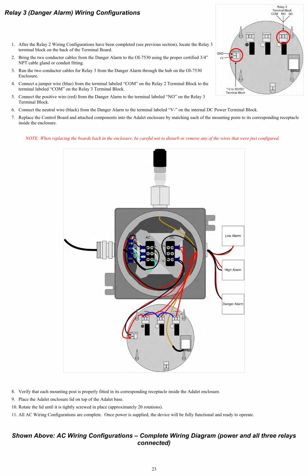
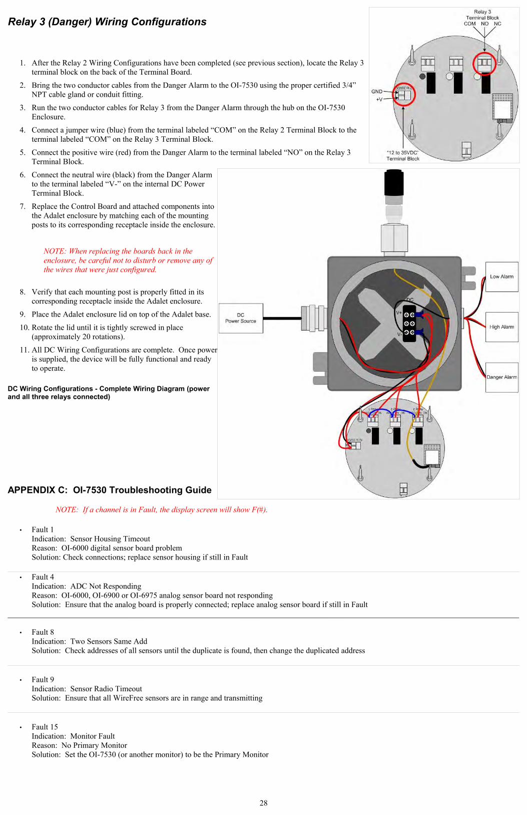
Relay 3 (Danger Alarm) Wiring Configurations
1. After the Relay 2 Wiring Configurations have been completed (see previous section), locate the Relay 3 terminal block on the back of the Terminal Board.
2. Bring the two conductor cables from the Danger Alarm to the OI-7530 using the proper certified 3/4” NPT cable gland or conduit fitting.
3. Run the two conductor cables for Relay 3 from the Danger Alarm through the hub on the OI-7530 Enclosure.
4. Connect a jumper wire (blue) from the terminal labeled “COM” on the Relay 2 Terminal Block to the terminal labeled “COM” on the Relay 3 Terminal Block.
5. Connect the positive wire (red) from the Danger Alarm to the terminal labeled “NO” on the Relay 3 Terminal Block.
6. Connect the neutral wire (black) from the Danger Alarm to the terminal labeled “V-” on the internal DC Power Terminal Block.
7. Replace the Control Board and attached components into the Adalet enclosure by matching each of the mounting posts to its corresponding receptacle inside the enclosure.
NOTE: When replacing the boards back in the enclosure, be careful not to disturb or remove any of the wires that were just configured.
8. Verify that each mounting post is properly fitted in its corresponding receptacle inside the Adalet enclosure.
9. Place the Adalet enclosure lid on top of the Adalet base.
10. Rotate the lid until it is tightly screwed in place (approximately 20 rotations).
11. All AC Wiring Configurations are complete. Once power is supplied, the device will be fully functional and ready to operate.
Shown Above: AC Wiring Configurations – Complete Wiring Diagram (power and all three relays connected)
23
APPENDIX B: DC Wiring Configurations
DC Wiring ConfigurationsTo ensure full-functionality, complete ALL of the following Wiring Configurations before installing the device in the field. Please read all of the following items BEFORE wiring the device:
● The relay outputs are Dry Contacts. The following relay wiring configurations are one example of a common wiring scenario. Wiring choices for certain applications may differ from what is described in this Operation Manual.
● Verify that there is no power being sent from the power supply while wiring the relays.
● Otis Instruments, Inc. recommends wiring the relays as “NO” for most applications. With a “NO” relay, the relay will only be triggered if gas is seen.
● The user may choose to wire the relays as “NC” if desired. To do so, connect the neutral wire from the power supply to the terminal labeled “NC” (Normally Closed) instead of the terminal labeled “NO” (Normally Open).
● The wire colors used in the following drawings are used for ease of displaying which wires go where. Although the wire colors used in these drawings are standard colors, not all applications will use the same wire colors.
● To ensure technician safety, always wire the relays BEFORE supplying power to the device.
● For optimal performance, the manufacturer recommends using a minimum of 22 gauge wire for all Wiring Configurations. Different loads require different gauge wire. Use appropriate wire size, depending on the voltage and current requirements.
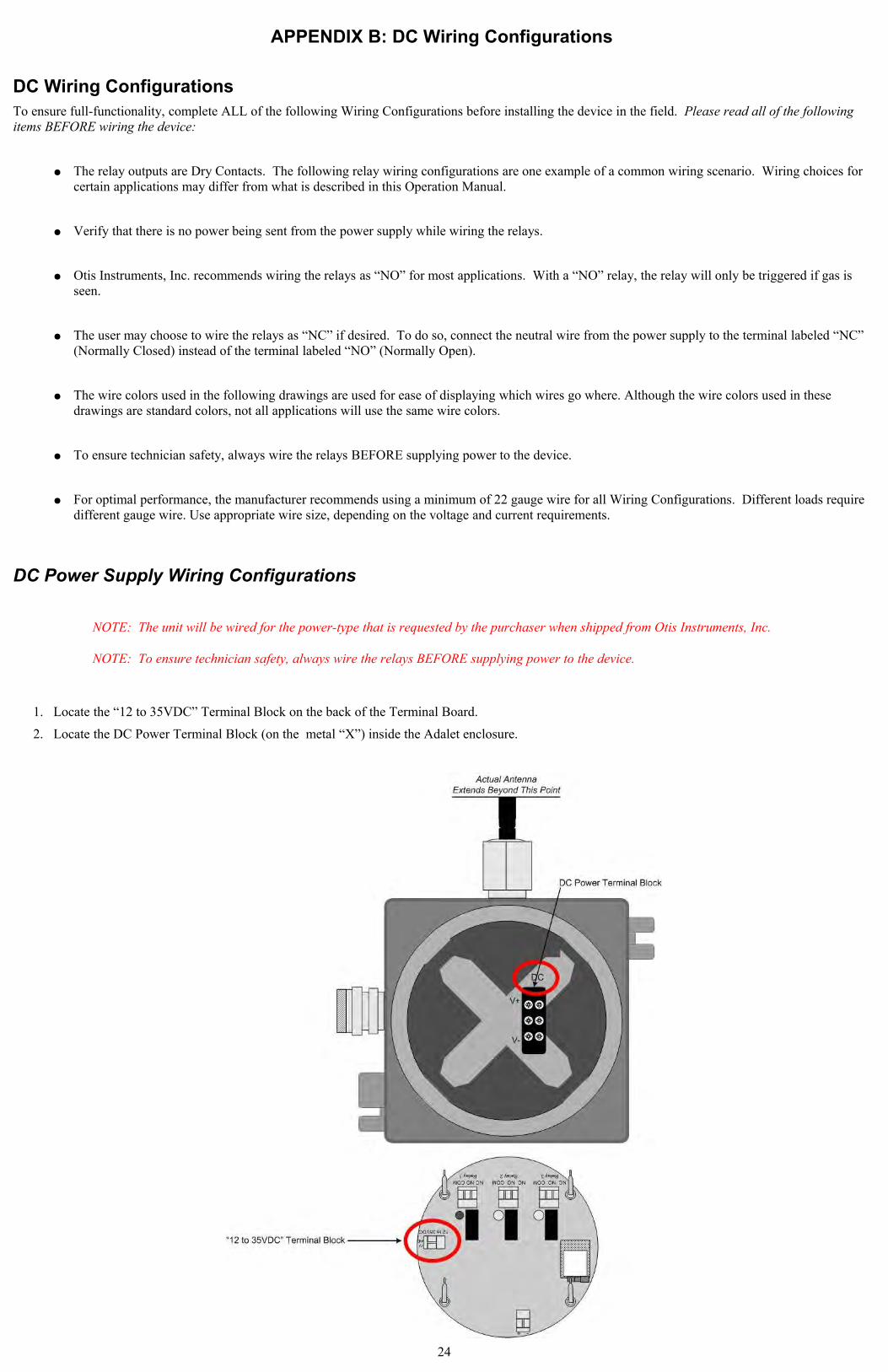
DC Power Supply Wiring Configurations
NOTE: The unit will be wired for the power-type that is requested by the purchaser when shipped from Otis Instruments, Inc.
NOTE: To ensure technician safety, always wire the relays BEFORE supplying power to the device.
1. Locate the “12 to 35VDC” Terminal Block on the back of the Terminal Board.
2. Locate the DC Power Terminal Block (on the metal “X”) inside the Adalet enclosure.
24
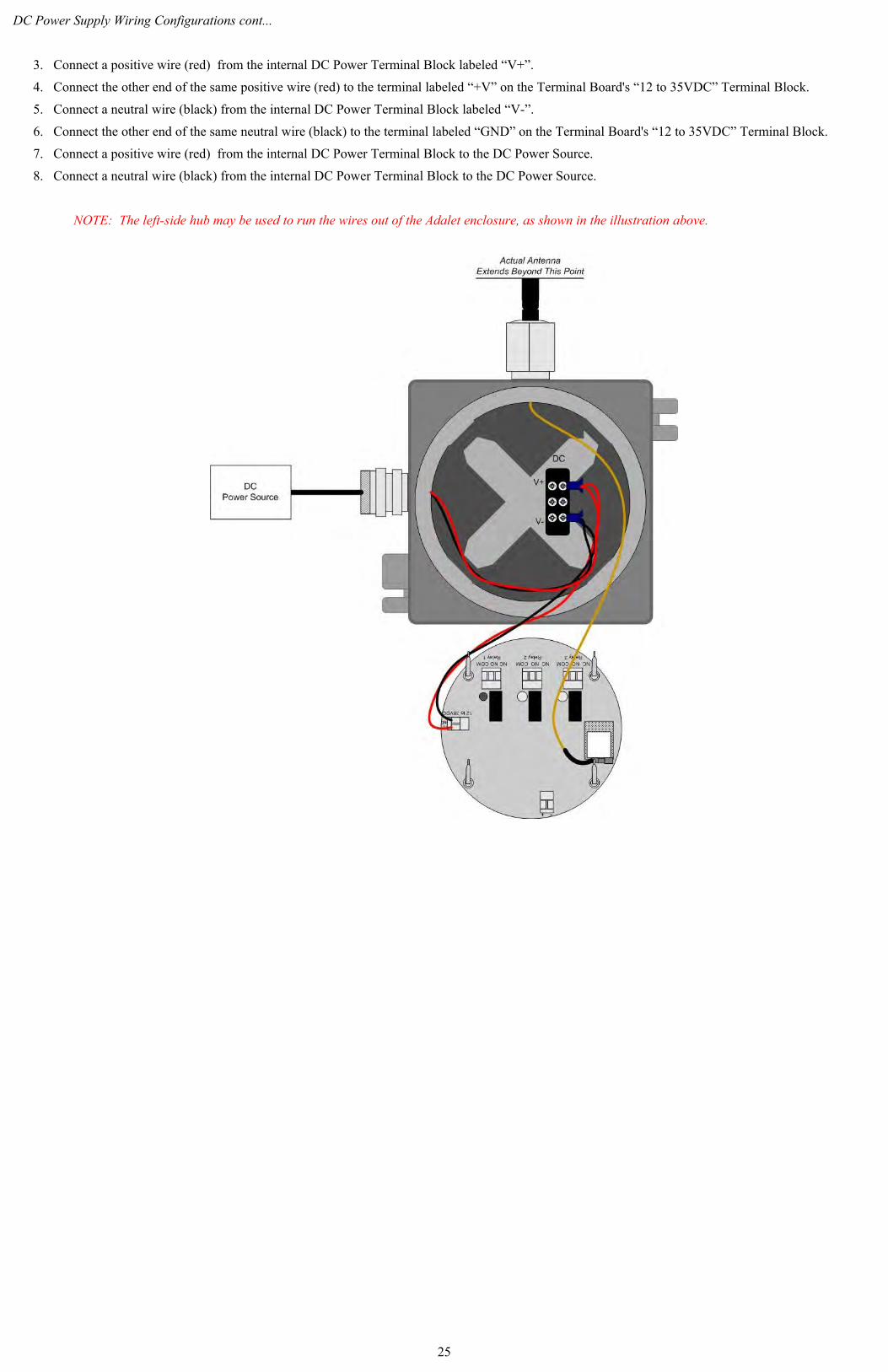
DC Power Supply Wiring Configurations cont...
3. Connect a positive wire (red) from the internal DC Power Terminal Block labeled “V+”.
4. Connect the other end of the same positive wire (red) to the terminal labeled “+V” on the Terminal Board's “12 to 35VDC” Terminal Block.
5. Connect a neutral wire (black) from the internal DC Power Terminal Block labeled “V-”.
6. Connect the other end of the same neutral wire (black) to the terminal labeled “GND” on the Terminal Board's “12 to 35VDC” Terminal Block.
7. Connect a positive wire (red) from the internal DC Power Terminal Block to the DC Power Source.
8. Connect a neutral wire (black) from the internal DC Power Terminal Block to the DC Power Source.
NOTE: The left-side hub may be used to run the wires out of the Adalet enclosure, as shown in the illustration above.
25

Relay 1 (Low Alarm) Wiring Configurations
1. Unscrew, remove and set aside the explosion proof Adalet lid.
2. Using the handles on the Front Panel, lift the Front Panel completely out of the Adalet enclosure to expose the terminals on the back of the Control Board.
NOTE: Do not use any metal object to remove the Front Panel from the Adalet enclosure.
3. Locate the Relay 1 terminal block on the back of the Terminal Board.
4. Bring the two conductor cables from the Low Alarm to the OI-7530 using the proper certified 3/4” NPT cable gland or conduit fitting.
5. Run the two conductor cables for Relay 1 from the Low Alarm through the hub on the OI-7530 Enclosure.
6. Connect a positive wire (red) from the terminal labeled “V+” on the Terminal Board's “12 to 35VDC” Terminal Block to the terminal labeled “COM” on the Relay 1 Terminal Block.
7. Connect the positive wire (red) from the Low Alarm to the terminal labeled “NO” on the Relay 1 Terminal Block.
8. Connect the neutral wire (black) from the Low Alarm to the terminal labeled “V-” on the internal DC Power Terminal Block.
9. Once the Relay 1 Wiring Configurations are complete, proceed to the next section.
26
Relay 2 (High Alarm) Wiring Configurations
1. After the Relay 1 Wiring Configurations have been completed (see previous section), locate the Relay 2 terminal block on the back of the Terminal Board.
2. Bring the two conductor cables from the High Alarm to the OI-7530 using the proper certified 3/4” NPT cable gland or conduit fitting.
3. Run the two conductor cables for Relay 2 from the High Alarm through the hub on the OI-7530 Enclosure.
4. Connect a jumper wire (blue) from the terminal labeled “COM” on the Relay 1 Terminal Block to the terminal labeled “COM” on the Relay 2 Terminal Block.
5. Connect the positive wire (red) from the High Alarm to the terminal labeled “NO” on the Relay 2 Terminal Block.
6. Connect the neutral wire (black) from the High Alarm to the terminal labeled “V-” on the internal DC Power Terminal Block.
7. Once the Relay 2 Wiring Configurations are complete, proceed to the next section.
27
Relay 3 (Danger) Wiring Configurations
1. After the Relay 2 Wiring Configurations have been completed (see previous section), locate the Relay 3 terminal block on the back of the Terminal Board.
2. Bring the two conductor cables from the Danger Alarm to the OI-7530 using the proper certified 3/4” NPT cable gland or conduit fitting.
3. Run the two conductor cables for Relay 3 from the Danger Alarm through the hub on the OI-7530 Enclosure.
4. Connect a jumper wire (blue) from the terminal labeled “COM” on the Relay 2 Terminal Block to the terminal labeled “COM” on the Relay 3 Terminal Block.
5. Connect the positive wire (red) from the Danger Alarm to the terminal labeled “NO” on the Relay 3 Terminal Block.
6. Connect the neutral wire (black) from the Danger Alarm to the terminal labeled “V-” on the internal DC Power Terminal Block.
7. Replace the Control Board and attached components into the Adalet enclosure by matching each of the mounting posts to its corresponding receptacle inside the enclosure.
NOTE: When replacing the boards back in the enclosure, be careful not to disturb or remove any of the wires that were just configured.
8. Verify that each mounting post is properly fitted in its corresponding receptacle inside the Adalet enclosure.
9. Place the Adalet enclosure lid on top of the Adalet base.
10. Rotate the lid until it is tightly screwed in place (approximately 20 rotations).
11. All DC Wiring Configurations are complete. Once power is supplied, the device will be fully functional and ready to operate.
DC Wiring Configurations - Complete Wiring Diagram (power and all three relays connected)
APPENDIX C: OI-7530 Troubleshooting Guide
NOTE: If a channel is in Fault, the display screen will show F(#).
• Fault 1Indication: Sensor Housing Timeout Reason: OI-6000 digital sensor board problemSolution: Check connections; replace sensor housing if still in Fault
• Fault 4Indication: ADC Not RespondingReason: OI-6000, OI-6900 or OI-6975 analog sensor board not respondingSolution: Ensure that the analog board is properly connected; replace analog sensor board if still in Fault
________________________________________________________________________________________________________________________________
• Fault 8 Indication: Two Sensors Same AddSolution: Check addresses of all sensors until the duplicate is found, then change the duplicated address
• Fault 9 Indication: Sensor Radio TimeoutSolution: Ensure that all WireFree sensors are in range and transmitting
• Fault 15Indication: Monitor FaultReason: No Primary Monitor Solution: Set the OI-7530 (or another monitor) to be the Primary Monitor
28
Specifications
Supply Voltage: 12-35 VDC or 120/240 Volts AC
Temperature: -30 to 70° C
Channels: 32 channels w/ individually configurable set-points
Relays: Three dry-contact (5 Amp) w/ 4 Amp fuses
Radio Options: · 2.4 GHz ISM, 100mW, 3 miles LOS
· 900 MHz (expected release: 1H 2011)
Antennas: Solid black – 900 MHz (domestic)Yellow tip – 2.4 GHz (international)
RF Connection: Class I, Div. 1; External N Female connector
Enclosure: Adalet Class I, Div. 1
Warranty: Hardware: One year (Limited)
_____________________________________________________________________________________
Warranty Statement for The GenII WireFree Relayer OI-7530
HardwareOtis Instruments, Inc. (Manufacturer) warrants its products to be free of defects in workmanship and materials—under normal use and service—from the date of purchase from the manufacturer or from the product's authorized reseller. The hardware for this device is under a one year limited warranty.
The manufacturer is not liable (under this warranty) if its testing and examination disclose that the alleged defect in the product does not exist or was caused by the purchaser's (or any third party's) misuse, neglect, or improper installation, testing or calibrations. Any unauthorized attempt to repair or modify the product, or any other cause of damage beyond the range of the intended use, including damage by fire, lightening, water damage or other hazard, voids liability of the manufacturer.
In the event that a product should fail to perform up manufacturer specifications during the applicable warranty period, contact the product's authorized reseller or return the product directly to the manufacturer with a Return Material Authorization (RMA). This number will be assigned upon contacting customer service at 979.776.7700 or [email protected]. The manufacturer will--at its option and expense--repair or replace the product, or deliver an equivalent product or part to the purchaser at no additional charge.
Any replaced or repaired product or part has either a 90-day warranty or the remainder of the initial warranty period (whichever is longer).
29

Otis Instruments, Inc.
Corporate Office2200 E. Villa Maria Dr.
Bryan, TX 77802979.776.7700
www.otisinstruments.com
30