
Model No. · pWindows® Internet Explorer® 8.0 is abbreviated to “Internet Explorer”. pIn this...
146
Operating Instructions <Operations and Settings> Live Switcher Model No. AV-HS410N ENGLISH VQT3U71A(E) M1111TY0 -FJ How the Operating Instructions are configured <Basics>: The <Basics> describes the procedure for connection with the required equipment and for installation. Before installing this unit, be sure to take the time to read through <Basics> to ensure that the unit will be installed correctly. <Operations and Settings> (this manual): This <Operations and Settings> describes how to operate the unit and how to establish its settings. For details on how to perform the basic menu operations, refer to “2-2. Basic menu operations” in the <Basics>.
Transcript of Model No. · pWindows® Internet Explorer® 8.0 is abbreviated to “Internet Explorer”. pIn this...

Operating Instructions <Operations and Settings>
Live Switcher
Model No. AV-HS410N
ENGLISHVQT3U71A(E)M1111TY0 -FJ
How the Operating Instructions are configured <Basics>: The <Basics> describes the procedure for connection with the required equipment and for installation.
Before installing this unit, be sure to take the time to read through <Basics> to ensure that the unit will be installed correctly.
<Operations and Settings> (this manual): This <Operations and Settings> describes how to operate the unit and how to establish its settings. For details on how to perform the basic menu operations, refer to “2-2. Basic menu operations”
in the <Basics>.

2
p Information on software for this product1. IncludedwiththisproductissoftwarelicensedundertheGNUGeneralPublicLicense(GPL)andGNULesserGeneral
PublicLicense(LGPL),andusersareherebyinformedthattheyhavetherighttoobtain,changeandredistributethesourcecodesofthissoftware.
Toobtainthesourcecodes,gotothefollowinghomepage:
http://pro-av.panasonic.net/
Themanufacturerasksuserstorefrainfromdirectinginquiriesconcerningthesourcecodestheyhaveobtainedandotherdetailstoitsrepresentatives.
2. IncludedwiththisproductissoftwarewhichislicensedunderMIT-License.
DetailsontheabovesoftwarecanbefoundontheCDprovidedwiththeunit.Refertothefoldercalled“LDOC”.(Detailsaregivenintheoriginal(Englishlanguage)text.)
Trademarks and registered trademarks
p Microsoft®,Windows®XP,WindowsVista®,Windows®7andInternetExplorer®areeitherregisteredtrademarksortrademarksofMicrosoftCorporationintheUnitedStatesandothercountries.p Intel®andIntel®CoreTMaretrademarksorregistered
trademarksofIntelCorporationintheUnitedStatesandothercountries.p Adobe®andReader®areeitherregisteredtrademarksor
trademarksofAdobeSystemsIncorporatedintheUnitedStatesand/orothercountries.p SDHCLogoisatrademarkofSD-3C,LLC.p Primatte®isaregisteredtrademarkofIMAGICADIGIXInc.p ThecopyrightsofPrimatte®belongtoIMAGICADIGIXInc.p ThepatentsforPrimatte®belongtoIMAGICADIGIXInc.p Othernamesofcompaniesandproductscontained
intheseOperatingInstructionsmaybetrademarksorregisteredtrademarksoftheirrespectiveowners.
About copyright and licence
Distributing,copying,disassembling,reversecompiling,reverseengineering,andalsoexportinginviolationofexportlawsofthesoftwareprovidedwiththisunitareexpresslyprohibited.
Abbreviations
Thefollowingabbreviationsareusedinthismanual.
p Microsoft®Windows®7ProfessionalSP132/64-bitisabbreviatedto“Windows7”.p Microsoft®WindowsVista®BusinessSP232-bitis
abbreviatedto“WindowsVista”.p Microsoft®Windows®XPProfessionalSP3andMicrosoft®
Windows®XPHomeEditionSP3areabbreviatedto“WindowsXP”.p Windows®InternetExplorer®8.0isabbreviatedto“Internet
Explorer”.p Inthismanual,modelAV-HS410Nisgivenas“AV-HS410”.p BothSDmemorycardsandSDHCmemorycardsare
describedas“memorycards”inthismanual.Whenindividualdescriptionsareprovided,theyarefeaturedindividually.p Personalcomputersarereferredtoas“computers”.
Illustrations and screen displays featured in the manual
p Whatisshowninthemanual’sillustrationsandscreendisplaysmaydifferfromhowitisactuallyappears.

3
Before use .................................................... 5Overview ........................................................................... 5
Concerning the ratings display ...................................... 5
Disclaimer of warranty .................................................... 5
Network security .............................................................. 5
Concerning differences in the system versions ........... 6
1. Basic operations ..................................... 7
1-1. Background transition ............................................. 7
1-1-1. Selectingthebus................................................ 7
1-1-2. SelectingthebususingtheSHIFTfunction....... 7
1-1-3. Selectingthebusmode...................................... 8
1-1-4. Selectingthetransitionmode............................. 8
1-1-5. Manualtransition................................................ 9
1-1-6. Autotransition.................................................... 9
1-1-7. Cuttransition...................................................... 9
1-2. Wipe ........................................................................ 10
1-2-1. Selectingthewipepattern................................ 10
1-2-2. Selectingthewipedirection............................. 11
1-2-3. Wipedecorations(border,softeffect).............. 11
1-2-4. Settingthewipestartposition.......................... 12
1-2-5. Modifyingwipe................................................. 12
1-2-6. Settingthelatency............................................ 14
1-3. Key ........................................................................... 15
1-3-1. Selectingthekeytype...................................... 15
1-3-2. Selectingthekeymaterial................................ 16
1-3-3. Keytransitions.................................................. 17
1-3-4. Keypreview...................................................... 19
1-3-5. Adjustingtheluminancekeyandlinearkey..... 19
1-3-6. Adjustingthechromakey................................. 20
1-3-7. Keydecorations................................................ 26
1-3-8. Maskingthekeysignals................................... 27
1-3-9. Flyingkey......................................................... 28
1-3-10. Settingthepriority............................................ 28
1-4. PinP (picture in picture)......................................... 29
1-4-1. SelectingthePinPchannelandmaterial......... 29
1-4-2. TransitionbetweenPinPmaterials................... 29
1-4-3. SelectingShape............................................... 30
1-4-4. PinPpreview.................................................... 30
1-4-5. PinPtransitions................................................ 30
1-4-6. PinPadjustments............................................. 31
1-4-7. LinkingPinP1andPinP2.................................. 32
1-4-8. PinPdecorations.............................................. 33
1-4-9. Trimmingsettings............................................. 34
1-5. DSK (downstream key) .......................................... 35
1-5-1. SelectingtheDSKtype.................................... 35
1-5-2. SelectingtheDSKmaterial.............................. 36
1-5-3. DSKtransitions................................................ 36
1-5-4. DSKpreview..................................................... 37
1-5-5. DSKadjustments............................................. 37
1-5-6. DSKdecorations.............................................. 38
1-5-7. MaskingtheDSKsignals................................. 39
1-6. Key Link .................................................................. 40
1-7. FTB (Fade to Black) ............................................... 41
1-8. Internal color signals ............................................. 42
1-8-1. Settingthecolorbackground........................... 42
1-8-2. SettingtheWasheffect.................................... 42
1-9. Switching the AUX output ..................................... 44
1-9-1. SelectingtheAUXoutputmaterials................. 44
1-9-2. AUX1transitions............................................... 44
1-9-3. Settingenable/disablefortheAUX1transition........................................................... 45
1-10. Memory ................................................................... 46
1-10-1. Memoryregistrationandrecallitems............... 47
1-10-2. Storingthesettingsinthememory(Store)...... 47
1-10-3. Recallingtheoperationsstoredinthememory(Recall)............................................................. 48
1-10-4. Memorypreview............................................... 49
1-10-5. Deletingtheoperationsstoredinthememory(Delete)............................................................ 50
1-10-6. Selectingthebuseswhosesettingsaretoberegisteredandorplayedback.......................... 51
1-10-7. Registeringthematerialselectionitems.......... 52
1-10-8. Settingeffectdissolve(shotmemory).................................................. 52
1-10-9. Editingeventmemorytimelines....................... 53
1-10-10.Registeringmemories(Register)..................... 59
1-11. Video memories ..................................................... 60
1-11-1. Recordingstillimages(Still)............................. 61
1-11-2. Recordingmovingimages(Clip)...................... 62
1-11-3. SavingImagesinFlashMemory...................... 63
1-11-4. Playingbackmovingimages(Clip).................. 64
1-12. Memory card ........................................................... 67
1-12-1. Initializingthememorycards........................... 69
1-12-2. Savingdataonmemorycards......................... 69
1-12-3. Loadingdatafrommemorycards.................... 70
1-12-4. Deletingfilesonmemorycards........................ 71
1-12-5. Displayingthememorycardinformation.......... 71
1-13. Waveform monitor settings ................................... 72
1-14. Setting the status display ...................................... 73
Contents

4
Contents
2. Input/output signal settings ................. 74
2-1. Input signal settings .............................................. 74
2-1-1. Settingtheframesynchronizer........................ 76
2-1-2. Settingtheinputmode..................................... 77
2-1-3. Settingthedelayamount................................. 78
2-1-4. Freezingtheinputsignals................................ 78
2-1-5. Settingthematerialnames.............................. 78
2-1-6. Settingtheup-converter................................... 79
2-1-7. Settingthevideoprocessfunction................... 80
2-1-8. Settingtheanaloginputgain(option).............. 80
2-1-9. Settingtheanalogcompositeinputsignals(option)............................................................. 81
2-1-10. SettingtheDVIinputsignals............................ 82
2-1-11. DisplayingtheDVIinputsignalinformation...... 86
2-1-12. AdjustingtheDVIinputsignals......................... 87
2-1-13. Automaticadjustmentoftheblacklevelandwhitelevel(analoginputsignals)..................... 87
2-2. Output signal settings ........................................... 88
2-2-1. Assigningtheoutputsignals............................ 89
2-2-2. SettingtheSDIoutputcolorrange................... 89
2-2-3. SettingtheDVIoutputsignals.......................... 90
2-2-4. Settingthedown-converter(option)................. 92
2-3. Setting the sync signals ........................................ 93
2-4. Adjusting the output signal phase ....................... 93
2-5. Setting the multi view display ............................... 97
2-5-1. Settingthescreenlayout.................................. 97
2-5-2. Settingthesplitframeandcharacters.............. 98
2-5-3. Settingthetallydisplays................................... 98
2-5-4. Changingthematerialnames.......................... 99
2-5-5. Settingthelevelmeters.................................. 100
2-5-6. Settingtheinputsignalmarks........................ 100
2-5-7. Settingthemarkers........................................ 100
2-5-8. High-resolutionmultiviewmode.................... 100
2-6. Setting the ancillary data and embedded audio data ............................................................. 101
3. System settings ................................... 102
3-1. Setting the system format ................................... 102
3-2. Setting the crosspoints ....................................... 103
3-2-1. Assigningsignalstothecrosspoints.............. 103
3-2-2. Settingthecrosspointswitching..................... 104
3-3. Button assignments............................................. 105
3-3-1. Settingtheuserbuttons................................. 105
3-4. Setting the date and time .................................... 106
3-5. Network settings .................................................. 106
3-6. Setting the built-in display backlight and button illumination ............................................... 107
3-7. Status displays ..................................................... 108
3-7-1. Alarmstatusdisplays..................................... 108
3-7-2. Alarmmessage.............................................. 108
3-7-3. Displayingtheversioninformationandoptioninformation........................................... 109
3-8. Initialization .......................................................... 110
3-8-1. Initializingsettingdata.................................... 110
3-8-2. Initializingfader.............................................. 110
4. External interfaces .............................. 111
4-1. Setting the GPI I/O ............................................... 111
4-2. LAN ........................................................................ 115
4-3. EDITOR .................................................................. 115
4-4. COM ....................................................................... 115
4-5. Plug-in software ................................................... 116
5. Setting menu table .............................. 117
Appendix (glossary) ................................ 139
Index ......................................................... 142

5
Before use
pwOverviewThisunitisa1MEdigitalvideoswitcherwhichsupportsamultiplenumberofHDandSDformats.Despiteitscompactsize,itcomeswitheightSDIinputs,oneDVI-Dinput,fiveSDIoutputsandoneDVI-Doutput.Theunitcomeswithaluminancekeyandchromakeysprovidedaskeyersinadditiontothebackgroundtransitionsbasedonthecut,mixandwipefunctions.ItalsohasoneDSKlineandtwoPinPlinesforenablingvideorecording,playbackandahostofothervideoproductionfunctions.Furthermore,usingthemultiviewdisplaysettings,thescreenofamonitorcanbesplitintoanumberofsectionstoaccommodateuptosixteenimages,enablingthenumberofmonitorstobereducedandaspace-savingsystemtobeconfiguredatlowcost.
pwConcerning the ratings displayTheunit’sname,modelnumberandelectricalratingsareindicatedonitssidepanel.
pwDisclaimer of warrantyINNOEVENTSHALLPanasonicCorporationBELIABLETOANYPARTYORANYPERSON,EXCEPTFORREPLACEMENTORREASONABLEMAINTENANCEOFTHEPRODUCT,FORTHECASES,INCLUDINGBUTNOTLIMITEDTOBELOW:
1ANYDAMAGEANDLOSS,INCLUDINGWITHOUTLIMITATION,DIRECTORINDIRECT,SPECIAL,CONSEQUENTIALOREXEMPLARY,ARISINGOUTOFORRELATINGTOTHEPRODUCT;
2PERSONALINJURYORANYDAMAGECAUSEDBYINAPPROPRIATEUSEORNEGLIGENTOPERATIONOFTHEUSER;
3UNAUTHORIZEDDISASSEMBLE,REPAIRORMODIFICATIONOFTHEPRODUCTBYTHEUSER;
4INCONVENIENCEORANYLOSSARISINGWHENIMAGESARENOTDISPLAYED,DUETOANYREASONORCAUSEINCLUDINGANYFAILUREORPROBLEMOFTHEPRODUCT;
5ANYPROBLEM,CONSEQUENTIALINCONVENIENCE,ORLOSSORDAMAGE,ARISINGOUTOFTHESYSTEMCOMBINEDBYTHEDEVICESOFTHIRDPARTY;
6ANYINCONVENIENCE,DAMAGESORLOSSESRESULTINGFROMACCIDENTSCAUSEDBYANINADEQUATEINSTALLATIONMETHODORANYFACTORSOTHERTHANADEFECTINTHEPRODUCTITSELF;
7LOSSOFREGISTEREDDATACAUSEDBYANYFAILURE;
8ANYDAMAGEORCLAIMSDUETOLOSSORLEAKAGEOFIMAGEDATAORSETTINGDATASAVEDONTHISUNITORONAMEMORYCARDORCOMPUTER.
pwNetwork securityTheunitalsohasfunctionswhichareusedwhenitisconnectedtoanetwork.Usingtheunitwhenithasbeenconnectedtoanetworkmaypossiblygiverisetothefollowingissues.
1Leakageortheftofinformationthroughthisunit2Useofthisunitforillegaloperationsbypersonswith
maliciousintent3Interferencewithorstoppageofthisunitbypersons
withmaliciousintent
Itisyourresponsibilitytotakeprecautionssuchasthosedescribedbelowtoprotectyourselfagainsttheabovenetworksecurityrisks.
p Usethisunitinanetworksecuredbyafirewall,etc.p Ifthisunitisconnectedtoanetworkthatincludes
computers,makesurethatthesystemisnotinfectedbycomputervirusesorothermaliciousentities(usingaregularlyupdatedantivirusprogram,anti-spywareprogram,etc.).
Thefollowingpointsshouldbeborneinmindaswell.p Usewiththesamesegmentisrecommendedforthe
equipmentwhichisconnectedtotheunit.Iftheunitisconnectedtoequipmentwhosesegmentsaredifferent,eventsdependentuponthesettingsinherenttothenetworkequipment,forinstance,mayoccursothoroughlychecktheconnectionswiththeequipmenttowhichtheunitwillbeconnectedpriortothestartofoperation.p Donotchooseaninstallationlocationwheretheunit,
cablesandotherpartswillbeeasilydamaged.

6
Before use
pwConcerning differences in the system versionsThismanualdescribesthefunctionswhichcanbeactuatedinanymodelwhosesystemversionisV2.00.00andup.Theapplicablefunctionsarereferredtoas“This function can be actuated in any model whose system version is V2.00.00 and up”.IfthemodelhasasystemversionbelowV2.00.00,thefunctionsconcernedcannotbeused.Neitherwillthemenusandmenuitemsconcernedbedisplayed.
pqHow to check the system versionTocheckthesystemversionofthisunit,selectSystemmenuMainVersionsubmenuSystemVersionitem,andcheckthedisplayforthisitem.Referto“3-7-3.Displayingtheversioninformationandoptioninformation”.
pqRestrictions on menus and functions[Restrictions on menus]
Menu Sub menu ItemModel with system
version V2.00.00 and up
Model with system version below V2.00.00
VideoMemory
Clip1PlayMode
Reverse —
Variable —
Clip2PlayMode
Reverse —
Variable —
TransSync Allitems —
Memory Allitems —
:Valid —:Invalid
[Restrictions on functions]
FunctionModel with system
version V2.00.00 and up
Model with system version below V2.00.00
Statusdisplay
Stillimage(Still)
— Onlyalistofthenamesisdisplayed.Movingimage(Clip)
Memorycard
Videomemorysaving
Theimagesinthevideomemoryaresavedintheflashmemoryarea.
—Theimagesinthevideomemorycannotbesavedautomatically.Savetheimagesmanuallyonthememorycard.
Movingimage(Clip)playback
Movingimage(Clip)operationsareperformedusingthenumberkeys.
—Movingimage(Clip)cannotbeoperatedusingthenumberkeys.Operatethemusingthemenu.
:Valid —:Invalid

7
1. Basic operations
1-1. Background transition
1-1-1. Selecting the busPressoneofthecrosspointbuttonstoselectthematerialtobeusedforthebackgroundtransition.Dependingontheoperatingstatus,thebuttonpressedwilllightinoneoftwocolors.
Lighting in red
WhentheselectedinputsignalsareoutputtoPGM.(However,theindicatorlightsinamberduringFTBoperations.)
Lighting in green
WhentheselectedinputsignalsarenotoutputtoPGM.
AUX BUS DELEGATION
PGMA
PSTB
AUX
1/13 2/14 3/15 4/16 5/17 6/18 7/19 8/20 9/21 10/22 11/23 12/24
AUX/DISP SOURCE
SHIFT
SHIFT
SHIFT
Lightinginred Lightingingreen
p Whenthecrosspointbuttonsarehelddown,thebuttonnumbersandthenamesoftheinputmaterialsassignedtothebuttonsaredisplayedonthebuilt-indisplayintheformofalistforaslongasthecrosspointbuttonsremainhelddown.
CROSS POINT ASSIGN
XPT:
SIG:
12
SHIFT
11
A1
10
DVI
9
IN8
8
IN7
7
IN6
6
IN5
5
IN4
4
IN3
3
IN2
2
IN1
1
BLK
XPT:
SIG:
24
SHIFT
23
None
22
CLN
21
KOUT
20
None
19
ST2V
18
ST1V
17
CBD1
16
CBAR
15
B2
14
B1
13
A2
1-1-2. Selecting the bus using the SHIFT function
TheSHIFTfunctionenablestwomaterialstobeallocated—thefrontmaterialandtherearmaterial—toonebutton,andthematerialstobeselectedusingthe[SHIFT]button.Atotalof24materials—frontmaterials(1to12)andrearmaterials(13to24)—canbeallocatedtothethreegroupsof12crosspointbuttonswhetherthesebuttonsarethePGM/Abuscrosspointbuttons,PST/BbuscrosspointbuttonsorAUXbuscrosspointbuttons.
ThereareactuallytwoSHIFTfunctions:“AllSHIFT”forswitchingallthefrontmaterialstotherearmaterialsorviceversa,and“SingleSHIFT”forswitchingthefrontmaterialofonecrosspointbuttonwithitsrearmaterialorviceversa.“AllSHIFT”worksoncetheSHIFTfunctionhasbeenallocatedtooneoftheuserbuttons.“SingleSHIFT”worksoncetheSHIFTfunctionhasbeenallocatedtotheNo.12orNo.1crosspointbuttonofthecrosspointbuttongroupconcernedbyamenuoperation.
All SHIFT
AllSHIFTisusedtoswitchallthematerialsofthePGM/Abuscrosspointbuttons,PST/BbuscrosspointbuttonsorAUXbuscrosspointbuttonsfromfrontmaterialstorearmaterialsorviceversa.TheuserbuttontowhichtheSHIFTfunctionhasbeenallocatedisusedtoswitchbetweenthefrontmaterialsandrearmaterials.
1AllocatetheSHIFTfunctiontooneoftheuserbuttons.(Forthemethodusedtoallocatethisfunctiontotheuserbutton,referto“3-3-1.Settingtheuserbuttons”.)
2Eachtimethe[SHIFT]button(userbutton)ispressed,thefrontmaterialsareswitchedtotherearmaterialsorviceversa.
Whentherearmaterials(13to24)havebeenselected,the[SHIFT]button(userbutton)lightsinamber.
Whenthebuttonispressedagain,itgoesoff,andthefrontmaterials(1to12)arenowselected.

8
1. Basic operations
Single SHIFT
SingleSHIFTisusedtoswitchtheindividualmaterialofaPGM/Abuscrosspointbutton,PST/BbuscrosspointbuttonorAUXbuscrosspointbuttonfromafrontmaterialtoarearmaterialorviceversa.SwitchingbetweenthefrontmaterialandrearmaterialisdoneusingthecrosspointbuttoninwhichtheSHIFTfunctionisallocated.TheSHIFTfunctioncanbeallocatedtobuttonNo.1orNo.12.
w Allocating the SHIFT function
1Pressthexbuttontolightitsindicator,anddisplaytheXPTmenu.
2Use[F1]todisplaytheXPTSettingsubmenu.
3Use[F2]toselectthebuttontowhichtheSHIFTfunctionistobeallocatedusingtheShiftitem.
Right ButtonNo.12
Left ButtonNo.1
Off Functionisnotallocated.
4Use[F3]toselecttheoperationtobeperformedwhenthe[SHIFT]buttonispressedusingtheShift-Lockitem.
Off Therearmaterialisselectedonlywhilethe[SHIFT]buttonispressed.
On Thefrontmaterialandrearmaterialareswitchedeachtimethe[SHIFT]buttonispressed.
TousethematerialsthathavebeensetinthebuttontowhichtheSHIFTfunctionisallocated,eithersettheSHIFTfunctionofforallocatetheSHIFTfunctiontoanotherbutton. Ifthe[SHIFT]buttonfor“SingleSHIFT”ispressedwhentherearmaterials(13to24)havebeenselectedusing“AllSHIFT”,thebuscrosspointbuttonsconcernedwillbeswitchedtothefrontmaterials.Whenthecrosspointbuttonsarehelddown,thebuttonnumbersandthenamesoftheinputmaterialsassignedtothebuttonsaredisplayedonthebuilt-indisplayintheformofalistforaslongasthecrosspointbuttonsremainhelddown.
1-1-3. Selecting the bus modeSelecttheA/Bbussystemorflip-flopsystem(PGM/PSTsystem)fromthesettingmenu.
1Pressthesbuttontolightitsindicator,anddisplaytheConfigmenu.
2Use[F1]todisplaytheOperatesubmenu.
3Use[F2],andselecttheA/BorPGM/PST(flip-flopsystem)usingtheBusModeitem.
A/B WhenthefaderleverisatsideA,thesignalsselectedbytheAbusarereplacedPGMmaterials.WhenthefaderleverisatsideB,thesignalsselectedbytheBbusarereplacedPGMmaterials.
PGM-A/PST-B
Usingaflip-flopsystem,thesignalsselectedbytheAbusarealwaysreplacedPGMmaterials,andthesignalsselectedbytheBbusarealwaysreplacedPSTmaterials.
PGM-B/PST-A
Usingaflip-flopsystem,thesignalsselectedbytheBbusarealwaysreplacedPGMmaterials,andthesignalsselectedbytheAbusarealwaysreplacedPSTmaterials.
1-1-4. Selecting the transition modeSelectthetransitionmodeusingtheMIXandWIPEbuttons.
1Pressthe[BKGD]buttoninthetransitionareasothatitsindicatorlightsinamber.Whenthe[BKGD]buttonand[KEY]buttonarepressedatthesametime,bothbuttonsareselected.
2Usethe[MIX]and[WIPE]buttonsinthetransitionareatoselectthebackgroundtransitionmode.Theindicatoroftheselectedbuttonlightsinamber.

9
1. Basic operations
1-1-5. Manual transitionOperatethefaderlevertoexecutetransitionsmanually.Ifthefaderleverhasbeenoperatedduringautotransition,autotransitionwillbeswitchedtomanualoperationassoonasthefaderpositionovertakestheamountofthetransitionbeingexecuted.ThebustallyLEDsontheleftofthefaderleverindicatetheprogrambusoutputstatus.
Top LED only lights PGM/Abusoutput
Top and bottom LEDs light
Duringthetransition
Bottom LED only lights
PST/Bbusoutput
1-1-6. Auto transitionp Whenthe[AUTO]buttonispressed,thetransitionis
executedautomaticallyusingthetransitiontimewhichhasbeenset.p Thetransitionisexecutedintheremainingtimewhenthe
[AUTO]buttonispressedwhilethefaderleverisbeingoperated.p TheautotransitiontimeissetusingtheTimemenu.
1Pressthetbuttontolightitsindicator,anddisplaytheTimemenu.
2Use[F1]todisplaytheBKGDsubmenu.
3Setthetransitiontime.
When setting the transition time in frame units Use[F4]tosetthetransitiontimeinframes.When setting the transition time in second units Use[F3]tosetthetimeinsecondsand[F4]tosetit
inframes.
ThedisplayunitissetbyselectingConfigmenuOperatesubmenuTimeUnititem.
Sec Thetimeisdisplayedasanumberofseconds.
Frame Thetimeisdisplayedasanumberofframes.
Anytimefrom0to999fcanbeset.Thetimewhichcanbesetwhensecondsareusedasthedisplayunitdiffersdependingonthesystemformat.
59.94i: max.33s09f 59.94p: max.16s39f
50i: max.39s24f 50p: max.19s49f
24PsF: max.41s15f 23.98PsF: max.41s15f
1-1-7. Cut transitionWhenthe[CUT]buttonispressed,thetransitionisexecutedinstantly.

10
1. Basic operations
1-2. Wipe
1-2-1. Selecting the wipe patternThewipepatternsareselectedusingthenumberkeys.
1Pressthe[BKGDPATT]button(or[KEYPATT]button).The[BKGDPATT]button(or[KEYPATT]button)indicatorlightsinamber,andthepatterntablescreenappearsonthebuilt-indisplay.
2Use[F1]toselectthepage.
3Useoneofthenumberkeystoselectthepattern.Thecorrespondingbuttonlightsinamber,andthepatternisswitched.
4Use[F5]toclosethetablescreen.
Thetablescreencanalsobeclosedbypressingthe[BKGDPATT]buttonor[KEYPATT]buttonandturningoffthebutton’sindicator.
pw Table of wipe patterns
p The“SQ2:8”patterntakeseffectwhenthe[KEYPATT]buttonhasbeenpressed.
4INS
MENUINPUT
VMEM
BKGDPATT
KEYPATT
TAKEENTER
� / +PAGE
PLAY
REC
STOP
XPTDSBL
<
CLIP 1
STILL 1
MEMORY / WIPE PATTERN / 10 KEY<< TRIM OFF>>
CLIP 2
STILL 2
REV
TRIM OUT
TRIM IN
9PASTE
6MOD
3REV
CUNDO
8COPY
5DEL
2>
.>>
7NEW
1<
0/10<<
>

11
1. Basic operations
1-2-2. Selecting the wipe directionOperatethewipedirectionselectorbuttonstoselectthewipedirectionforthebackgroundtransition.(Thekeytransitionsaresetbythemenu.Thedirectionwhichissetherewillnotbereflected.)See“1-3-3.Keytransitions”.
A
N
B
B
A
B
A
B
A
B
R
A
A B
A
N/R
B
A B
When the [R] indicator is off: Wipingproceedsinthenormaldirection.
When the [R] indicator is lit: Wipingproceedsinthereversedirection.
When the [N/R] indicator is lit: Thenormaldirectionisreplacedwiththereverse
direction(orviceversa)whenthetransitioniscompleted.(Thelitandextinguishedstatusesofthe[R]buttonarealsoswitchedinlinewiththedirectionofthewiping.)
1-2-3. Wipe decorations (border, soft effect)
Abordereffectorsofteffectcanbeaddedtothewipingofbackgroundtransitions.
Setting the border and soft effect
1Pressthebbuttontolightitsindicator,anddisplaytheBackgroundmenu.
2Use[F1]todisplaytheBordersubmenu.
3Use[F2]tosetOn(orOff)fortheborderusingtheBorderitem.
4Use[F3]tosetthewidthoftheborderusingtheWidthitem.
5Use[F4]tosettheamountofsofteffectusingtheSoftitem.When“On”hasbeenselectedastheBorderitemsetting,theratioofthesofteffecttotheborderwidthisindicatedastheamountofsofteffect.Whenonlythesofteffectistobeaddedtowipe,select“Off”astheBorderitemsetting.
Setting the border color
1OntheBackgroundmenu,use[F1]todisplaytheBorderColorsubmenu.
2Use[F2],[F3]and[F4]toadjusttheHue,SatandLumofthebordercolor.
w To call the preset color
Use[F5]toselectthepresetcolorusingtheLoaditem,andpressthe[F5].
When[F5]ispressed,whathasbeensetsofariscanceledandreplacedwiththepresetcolorvalues.
Tosavethevaluesthatweresetbeforecallingthepresetcolor,referto“1-10.Memory”.

12
1. Basic operations
1-2-4. Setting the wipe start positionWipestartcanbesetatanydesiredposition.
Target patterns:WIPE1: 5WIPE2: 4,5,6,7SQ1: 5SQ2: 4,5,6,7
TheWIPEpatternissetusingtheWIPEPositionsubmenuoftheBackgroundmenu(orKeymenu).Inthesameway,theSQpatternissetusingtheSQPositionsubmenuoftheBackgroundmenu(orKeymenu).
1Pressthebbutton(orkbutton)tolightitsindicator,anddisplaytheBackgroundmenu(orKeymenu).
2Use[F1]todisplaytheWIPEPositionsubmenu(orSQPositionsubmenu).
3Eitheroperatethepositionersoruse[F2]and[F3]tosetthewipestartpositionusingtheX-PositemandY-Positem.Thissettingispossibleonlyifthetargetpatternhasbeenselectedforthebackgroundorkeypattern.
4Eitheroperatethefaderleverorpressthe[AUTO]buttontocheckthewipeoperation.(When,forinstance,–50hasbeensetforX-Posand–50forY-Pos,thefollowingscreen(orkey)appearsfromthebottomleftandwipeisperformedwhilethescreen(orkey)movestothescreencenter.)
<X-Pos, Y-Pos setting range>
Insidescreenarea Outsidescreenarea
5Tocopythestartpositionsetting,press[F5](CopytoKeyorCopytoBKGD).Thebackgroundsettingiscopiedtothekeysettingwhilethekeysettingiscopiedtothebackgroundsetting.
1-2-5. Modifying wipe
Setting the 3D (page turning) effect
Alightingeffectcanbeaddedtoawipepattern.Alternatively,thepageturningeffectparametercanbeset.Theseeffectscanbesetforbackgroundtransitionsandkeytransitions.
Target patterns:3D1:1,3,7,9
1Pressthebbutton(orkbutton)tolightitsindicator,anddisplaytheBackgroundmenu(orKeymenu).
2Use[F1]todisplaythe3DModifysubmenu.
3Use[F2]toselectwhetherthelightingeffectistobeaddedusingtheLightitem.
On Thelightingeffectisadded.
Off Thelightingeffectisnotadded.
4Use[F3]tosetthesizewhenimageshavebeenreducedusingtheSizeitem.
5Use[F4]tosettheradiusofthepageturningeffectusingtheRadiusitem.
6Use[F5]tosetthedirectionofthepageturningeffectusingtheAngleitem.

13
1. Basic operations
Setting the trimming
Thetrimmingatthetimeabackgroundtransitionisexecutedcanbeset.
Target patterns:SQ1,SQ2,SL,3D1,3D2
The“4:3”and“4:3Smth”settingsfortheTrimitemtakeeffectwhentheHDformathasbeenselectedasthesystemformatsetting.
1OntheBackgroundmenu,use[F1]todisplaytheModifysubmenu.
2Use[F2]tosetthetrimmingoperationandtransitionoperationusingtheTrimitem.
16:9 (On) Fortrimmingtheedgesaroundthematerial.Thissettingisusedwhenablackborder,forinstance,canbeseenaroundthematerial.WhenHDhasbeenselectedasthesystemformatsetting,“16:9”isdisplayedonthemenu,butwhenSDhasbeenselectedasthesystemformatsetting,“On”isdisplayedonthemenu.
4:3 Fortrimmingusingthe4:3aspectratioandreleasingthetrimmingwhenthetransitioniscompleted.
4:3Smth Fortrimmingusingthe4:3aspectratioandexecutingthetransitionto16:9imagessmoothly.
Off Notrimming
3Use[F3]toselectthesettingforautomatictrimming(4:3or4:3Smth)inaccordancewiththematerialusingthe4:3Autoitem.
Off Allinputmaterialsaretargetedforautomatictrimming.
On Usingtheup-convertersetting,theinputmaterialsforwhich“EdgeCrop”isselectedaretargetedforautomatictrimming.

14
1. Basic operations
1-2-6. Setting the latencyAdelayamountcanbesetforthebackgroundimageorkeyimage.
1Pressthesbuttontolightitsindicator,anddisplaytheConfigmenu.
2Use[F1]todisplaytheLatencysubmenu.
3Use[F2]tosetthedelayamountforthebackgroundimageusingtheBKGDitem.Alternatively,use[F3]tosetthedelayamountforthekeyimageusingtheKeyitem.
1F Fix Theimageisdelayedbyoneframe(1F).Therewillbenooriginalimageremaining
whenwipeiscompleted(whenSQ1,SQ2,SL,3D1or3D2hasbeenselectedasthewipepattern).
Minimum Theimageisnotdelayed.However,theimagewillbedelayedbyone
frame(1F)whenSQ1,SQ2,SL,3D1or3D2hasbeenselectedasthewipepatternorwhentheflyingkeyhasbeenselected.
w BKGD itemsDelay amount setting
Attimesotherthanduringtransitions
MIX/WIPE SQ/SL/3D
Minimum Nodelay Nodelay 1Fdelay
1F Fix 1Fdelay 1Fdelay 1Fdelay
w Key itemsDelay amount setting
Attimesotherthanduringtransitions
MIX/WIPESQ/SL/3D/Flyingkey
Minimum Nodelay Nodelay 1Fdelay
1F Fix 1Fdelay 1Fdelay 1Fdelay

15
1. Basic operations
1-3. KeyThisoperationcombinesthebackgroundimagewithanotherimage.Thekeydefinitioncanbeadjusted,andanedgecanbeaddedtothecombinedimage.
AlsoavailableasmaterialsbesidesKEYforcombiningwiththebackgroundimagearePinP(pictureinpicture)andDSK(downstreamkey).Thedefaultsettingsforpriority(imagepositioning)areasshowninthefigurebelow.
<Priority default settings>
Key
PinP1
PinP2
DSK
Background image
ThepriorityforKey,PinP1andPinP2canbechanged.Referto“1-3-10.Settingthepriority”.
Howkeycombinationsworkisshowninthefigurebelow.
<How key composition works>
HS410
HS410
Background
Key source
Key fill
Output image Invert
1-3-1. Selecting the key type1Pressthekbuttontolightitsindicator,anddisplaythe
Keymenu.
2Use[F1]todisplaytheKeysubmenu.
3Use[F2]toselecttheTypeitem.
Lum (luminance key/self key)
Thisisforcreatingthekeysignalsfromtheluminancecomponentorluminanceandchromacomponentofthekeyfillsignal.
Linear (linear key/ EXT key)
Thisisforcreatingthekeysignalsfromtheluminancecomponentofthekeysourcesignal.Itisusedwhenthekeysourcesignalandkeyfillsignalaredifferent.
Chroma (chroma key/ self key)
Thisisforcreatingthekeysignalsusingaspecifichueofthekeyfillsignalasthereference.
Full (full key/self key)
Thisisforcreatingthekeysignalsusingtheimagesonthefullscreenasthekeysourcesignals.PinPcombinationsarepossibleinconjunctionwiththeflyingkey.See“1-3-9.Flyingkey”.
Sincetheluminanceandchromakeysareoperatedasselfkeys,thekeyfillsignalsareusedasthekeysourcesignals.Forthefullkey,theimagesonthefullscreenareusedasthekeysourcesignals.Whentheluminancekey,chromakeyorfullkeyhasbeenselectedasthekeytype,thekeysignalswillremainunchangedevenwhenthekeysourcesignalsareswitched.
Whenusingthelinearkey,usematerialwithablackbackgroundandwhitecharactersorshapetobecombinedbythekeyasthekeysourcesignal.Materialwhichisnotblackandwhitemaynotbecombinedclearly.Materialwithawhitebackgroundandblackcharacters,etc.canbereversedusingthekeyinvertfunctionforuse.

16
1. Basic operations
4Whentheluminancekeyhasbeenselected,thechromacomponentcanbeincludedinthegenerationofthekeysignalsinviewoftheselfkeyapplication.(Thisdoesnotapplytothelinearkey.)Use[F3],andselectthesettingusingtheLumKeyitem.
Chroma On Inadditiontotheluminancecomponent,thechromacomponentisalsotakenintoaccountinthegenerationofthekeysignals.Thisisthesettingforusingacolorwithalowluminancecomponentforthekeysignals(suchaswhendefiningbluecharacters).
Chroma Off Thekeysignalsaregeneratedfromonlytheluminancecomponent.
5Use[F4]toselectthefilltypeusingtheFillitem.
Bus Thebussignalisusedforthekeyfillsignal.
Matte Theinternalfillmatteisusedforthekeyfillsignal.
1-3-2. Selecting the key material
Selecting the key fill and key source signals
Pressthe[KEY]buttonintheAUXbusselectionarea,andswitchtheselectionofthekeyfillsignal(indicatorlightsinamber)andkeysourcesignal(indicatorlightsingreen).
<Selecting the key fill signal>Withtheindicatorofthe[KEY]buttonlitinamber,pressoneoftheAUXbuscrosspointbuttons1to12toselectthekeyfillsignal.TheindicatoroftheselectedAUXbuscrosspointbuttonlightsinamber.(ItwilllightinrediftheselectedsignalisbeingoutputfromthePGMconnector.)
AMBER : FILL / GREEN : SOURCE
KEY PinP1 PinP2 DSK AUX1 AUX2 AUX3 AUX4 DISP MV
AUX BUS DELEGATION
AUX
AUX/DISP SOURCE
SHIFT
PGMPVW
Lightinginamber
<Selecting the key source signal>Withtheindicatorofthe[KEY]buttonlitingreen,pressoneoftheAUXbuscrosspointbuttons1to12toselectthekeysourcesignal.TheindicatoroftheselectedAUXbuscrosspointbuttonlightsingreen.(ItwilllightinrediftheselectedsignalisbeingoutputfromthePGMconnector.)Sincetheluminanceandchromakeysareoperatedasselfkeys,thekeyfillsignalsareusedasthekeysourcesignals.Whentheluminancekeyorchromakeyhasbeenselectedasthekeytype,thekeysignalswillremainunchangedevenwhenthekeysourcesignalsareswitched.
AMBER : FILL / GREEN : SOURCE
KEY PinP1 PinP2 DSK AUX1 AUX2 AUX3 AUX4 DISP MV
AUX BUS DELEGATION
AUX
AUX/DISP SOURCE
SHIFT
PGMPVW
Lightingingreen

17
1. Basic operations
Setting the fill matte color
1Pressthekbuttontolightitsindicator,anddisplaytheKeymenu.
2Use[F1]todisplaytheFillMattesubmenu.
3Use[F2],[F3]and[F4]toadjusttheHue,SatandLumofthefillmatte.
w To call the preset color
Use[F5]toselectthepresetcolorusingtheLoaditem,andpressthe[F5].
When[F5]ispressed,whathasbeensetsofariscanceledandreplacedwiththepresetcolorvalues. Tosavethevaluesthatweresetbeforecallingthepresetcolor,referto“1-10.Memory”.
1-3-3. Key transitions1Selectthetransitionmode.
Pressthe[KEY]buttoninthetransitionareatolightitsindicator.Toexecuteabackgroundtransitionandkeytransitionatthesametime,pressthe[BKGD]buttonand[KEY]buttontogethertoturnonbothindicators.
CUT AUTO
MIX
MIX WIPE
N/R R
BKGD KEY KEYON
FTBON
PinP1ON
PinP2ON
DSKON
WIPE DIRECTION
WIPE
MIX
WIPE
2Selectthetransitiontype.Usethe[MIX]buttonor[WIPE]buttoninthetransitionareatoselectthekeytransitionmode.Theselectedbuttonlightsinamber,andtheMIXorWIPEstatusindicatorLEDdependingontheselectedmodelights.IfWIPEhasbeenselected,pressthe[KEYPATT]buttoninthememory/wipepattern/numberkeyareatolightitsindicator,andselectthewipepattern.
4INS
MENUINPUT
VMEM
BKGDPATT
KEYPATT
TAKEENTER
� / +PAGE
PLAY
REC
STOP
XPTDSBL
<
CLIP 1
STILL 1
MEMORY / WIPE PATTERN / 10 KEY<< TRIM OFF>>
CLIP 2
STILL 2
REV
TRIM OUT
TRIM IN
9PASTE
6MOD
3REV
CUNDO
8COPY
5DEL
2>
.>>
7NEW
1<
0/10<<
>
3Setthetimeofthetransition.OntheTimemenu,use[F1]todisplaytheKeysubmenu.Aswithabackgroundtransition,setthetransitiontime.

18
1. Basic operations
4Setthewipedirection.OntheKeymenu,use[F1]todisplaytheTransitionsubmenu.Use[F1]toset“Normal”or“Reverse”usingtheKeyoutPatternitem.
Normal Thekeyoutpatternmovesinthesamedirectionasthekeyinpattern.
Reverse Thekeyoutpatternmovesintheoppositedirectionfromthekeyinpattern.
<Pattern examples>
Patternexample1 Patternexample2Patternexample3WIPE1:5WIPE2:1to7
Patternexample4SQ1: 5SQ2: 1,2,4to73D1: 53D2: 1to3
Keyin SQSQ
Keyout(Normal)
SQSQ
Keyout(Reverse)
SQSQ
:Thisindicatestheareaswherekeysarecombined.
Theoperationsforpatternexample3areperformedforthe“WIPE1:5”and“WIPE2:1to7”patterns. Theoperationsforpatternexample4areperformedforthe“SQ1:5”,“SQ2:1,2,4to7”,“3D1:5”and“3D2:1to3”patterns.Thesameoperationsareperformedfornormalandreverse.
5Executethetransition.Pressthe[AUTO]buttoninthetransitionareatoautomaticallyexecutethetransitionatthetransitiontimethathasbeenset.Alternatively,executethetransitionmanuallybyoperatingthefaderlever.
Key auto transition
Whenthe[KEYON]buttoninthetransitionareaispressed,thetransitionisautomaticallyexecutedatthetransitiontimethathasbeenset.Duringkeyin,theindicatorofthe[KEYON]buttonblinksinred,anditlightsinredwhenthetransitioniscompleted.Ifthe[KEYON]buttonispressedwiththepicturecompletelykeyedin,theKeyimagetransition(keyout)isexecuted.Duringkeyout,theindicatorofthe[KEYON]buttonlightsinred,anditgoesoffwhenthetransitioniscompleted.Ifthe[KEYON]buttonispressedduringthetransition,thetransitiondirectionisreversed.

19
1. Basic operations
1-3-4. Key previewKeypreviewimagescanbeoutputtothepreviewoutput,andthekeyscanbeadjustedandchecked.
1OntheKeymenu,use[F1]todisplaytheKeysubmenu.
2Use[F5]tosetthepreviewmodeusingthePVWitem.
On Animagewithkeyeffectsaddedisoutputtothepreviewoutput.
Off Animagewithnokeyeffectsaddedisoutputtothepreviewoutput.
Auto Thepreviewimageofthenexttransitionisoutputtothepreviewoutput.
WhenauserbuttontowhichtheOn/Offsettingshavebeenallocatedispressed,thesettingisswitchedalternatelybetweenOn(buttonindicatorlights)andOff(buttonindicatorextinguished),andthe“Auto”settingisnotselected.
Menu User button When the user button is pressed
On Lights Off:Extinguished
Off Extinguished On:Lights
Auto Extinguished On:Lights
When“Auto”isselectedusingamenuoperation,theuserbuttonindicatoristurnedoff(extinguished).
1-3-5. Adjusting the luminance key and linear key
Thesestepsaretakentoadjusttheluminancekeyandlinearkeydefinition.
1Pressthekbuttontolightitsindicator,anddisplaytheKeymenu.
2Use[F1]todisplaytheAdjustsubmenu.
3Use[F2],[F3]and[F4]toadjustthekeydefinition.
4Use[F5]tosetkeyinvert.When“On”isselected,thekeysignalstobegeneratedinternallyareinverted.
Operation/Parameter
Description of setting Setting range
F2/Clip
Referencelevelforgeneratingkeysignals
0.0to108.0
F3/Gain
Keyamplitude 0.0to200.0
F4/Density
Keydensity 0.0to100.0
F5/Invert
Keysignalinversion On,Off

20
1. Basic operations
1-3-6. Adjusting the chroma keySamplingisexecutedfortheselectedkeymaterialstoadjustthoseaspectsofthekeythataretobecompensated.
Step 1
w To execute the sampling automatically
1Pressthekbuttontolightitsindicator,anddisplaytheChromaKeymenu.
2Use[F1]todisplaytheAutoComputesubmenu.
3Press[F2]toexecutethesamplingautomatically.Toundowhathasbeensampled,press[F5].
w To execute the sampling manually
1Pressthekbuttontolightitsindicator,anddisplaytheChromaKeymenu.
2Use[F1]todisplaytheSamplesubmenu.
3Use[F2]toselect“Composite”(compositeimagethatcombinesthebackgroundimageandkey)usingtheViewitem.
4Use[F3]toselect“SelectBGColor”usingtheModeitem.
Select BG Color
Acolorforthebackgroundoftheforegroundimageisspecified.Normally,eitherablueorgreenbackgroundisspecified.
5Usethepositionertomovethepositionofthesamplemarker.Tochangethesizeofthesamplemarker,turntherotaryencoder[Z].
6Ifthesampleareathathasbeensetisacceptable,presstherotaryencoder[Z].Theareathathasbeensetisnowsampled.
7Toreturntothepre-samplingstatusaftersamplinghasbeenexecuted,press[F5].Thenumberofoperationsthatcanbeundoneisoneonly.

21
1. Basic operations
Step 2
Theobjectiveofthisstepistoremovethenoiseinthebackgroundimage.Thenoiseisremovedbycarryingoutthisstepseveraltimes.
1OntheChromaKeymenu,use[F1]todisplaytheSamplesubmenu.
2Use[F2]toselect“Matte”(Matteimage)usingtheViewitem.
3Use[F3]toselect“CleanBGNoise”usingtheModeitem.
Clean BG Noise
Thenoiseinthebackgroundimageisremoved.
4Usingthepositioner,movethepositionofthesamplemarkertothepositionofthenoise(whitedots)inthebackgroundimage.Tochangethesizeofthesamplemarker,turntherotaryencoder[Z].
5Ifthesampleareathathasbeensetisacceptable,presstherotaryencoder[Z].Thenoiseintheareathathasbeensetisnowremoved.
6Toreturntothepre-samplingstatusaftersamplinghasbeenexecuted,press[F5].Thenumberofoperationsthatcanbeundoneisoneonly.
Afterthenoiseisremoved
Beforethenoiseisremoved
Step 3
Theobjectiveofthisstepistoremovethenoiseintheforegroundimage.Thenoiseisremovedbycarryingoutthisstepseveraltimes.
1Use[F2]toselect“Matte”(Matteimage)usingtheViewitem.
2Use[F3]toselect“CleanFGNoise”usingtheModeitem.
Clean FG Noise
Thenoiseintheforegroundimageisremoved.
3Usingthepositioner,movethepositionofthesamplemarkertothepositionofthenoise(blackdots)intheforegroundimage.Tochangethesizeofthesamplemarker,turntherotaryencoder[Z].
4Ifthesampleareathathasbeensetisacceptable,presstherotaryencoder[Z].Thenoiseintheareathathasbeensetisnowremoved.
5Toreturntothepre-samplingstatusaftersamplinghasbeenexecuted,press[F5].Thenumberofoperationsthatcanbeundoneisoneonly.
Afterthenoiseisremoved
Beforethenoiseisremoved

22
1. Basic operations
Step 4
Aftersteps1to3havebeencarriedout,noisewillstillremaininthedetailareassuchasthesubject’shairasshownintheimagebelow.Noiseremaininginthedetailareasisalsoremovedin“step4”.Iftherearemanyareaswithnoise,thenoiseisremovedbycarryingoutthisstepseveraltimes.Iftherearefewareaswithnoise,adjustthenoiseusingtheModeitem(“Spill+”and“Spill–”)oftheSamplesubmenu.
1Use[F2]toselect“Composite”(compositeimagethatcombinesthebackgroundimageandkey)usingtheViewitem.
2Use[F3]toselect“SpillSponge”usingtheModeitem.
Spill Sponge Thenoiseremaininginthedetailedareasisremoved.
3Usingthepositioner,movethepositionofthesamplemarkertothepositionoftheremainingnoise.Tochangethesizeofthesamplemarker,turntherotaryencoder[Z].
4Ifthesampleareathathasbeensetisacceptable,presstherotaryencoder[Z].Thenoiseintheareathathasbeensetisnowremoved,andthecolorsbecomemorenatural.
5Toreturntothepre-samplingstatusaftersamplinghasbeenexecuted,press[F5].Thenumberofoperationsthatcanbeundoneisoneonly.
Executesamplinginboththelightanddarkareasasthesamplearea. Ifthenoiseintheforegroundimageisnotcompletelyremovedbycarryingoutthestepsabove,proceedwiththeFineTuningsubmenuoperation.
Step 5
Theobjectiveofthisstepistofinelyadjusttheimagebyadjustingthenoiseandtransparency,forexample.
1OntheChromaKeymenu,use[F1]todisplaytheSamplesubmenu.
2Use[F2]toselecttheimagetobeadjustedusingtheViewitem.
Composite Compositeimagethatcombinesthebackgroundimageandkey
Matte Matteimage
Proc.FG Processforegroundimage
FG Foregroundimage
3Use[F3]toselecttheadjustmentfunctionusingtheModeitem.Fordetailsontheitems,refertothefollowingpages.
4Usingthepositioner,movethepositionofthesamplemarkertothepositiontobesampled.Tochangethesizeofthesamplemarker,turntherotaryencoder[Z].
5Ifthesampleareathathasbeensetisacceptable,presstherotaryencoder[Z].Theareathathasbeensetisnowsampled.
6Toreturntotheconditionofastepearlierafteranadjustmenthasbeenmade,press[F5].Thenumberofoperationsthatcanbeundoneisoneonly.

23
1. Basic operations
[Spill–] [Spill+]Inthesemodes,thenoiseintheforegroundimagecanberemovedorrestoredstepbystepthroughrepeatedsampling.
[+] Spill [–]
[Matte–] [Matte+]Inthesemodes,thematteinformationisadjusted.If,forinstance,theareaofshadowintheforegroundimageistobemadelighter,use[Matte−]toadjust.Conversely,tomakeitdarker,use[Matte+].Transparentimagessuchasimagesofsmokeorwatercanbemadetostandoutmore.
[–] Matte [+]

24
1. Basic operations
[Detail–] [Detail+]Inthesemodes,thenoiseinthebackgroundimagecanberemovedstepbystep.Thisisausefulwayofadjustingimageslostbyothersamplingoperationstoadjustthetextureortransparencyofimages.
[–] Detail [+]
[Matte Sponge]Inthismode,thesemi-transparentpartsofthesubjectinaforegroundimageareselectedandmadematte(non-transparent).Unlike[CleanFGNoise]ontheSamplesubmenu,thecolorinformationisnotchangedintheprocess.With[CleanFGNoise],thecolorsoftheselectedpartsarerestoredtotheiroriginalcolorsbut,with[MatteSponge],onlythesemi-transparentkeysaremadematte(non-transparent)whilethecolorsremainunchangedandtheoriginalcolorsarenotrestored.
[Make FG Trans]Inthismode,thetransparencyofareaswithalowtransparencyintheforegroundimageisincreased.Thisisusefulwhen,forinstance,areascoveredwithdarksmokeorcloudsinaforegroundimagearetobemadesemi-transparent.
[Restore Detail]Inthismode,thetransparencyofareaswithahightransparencyinthebackgroundimageisreduced.Thisisusefulwhen,forinstance,restoringthedetailsofanimage(suchasanimagewithasubjectwhohasloosehairoranimagewithsmoke),whichhavebeenlostasaresultofa[CleanBGNoise]orothersuchoperationontheSamplesubmenu,towhattheywereintheoriginalimage.
25
1. Basic operations
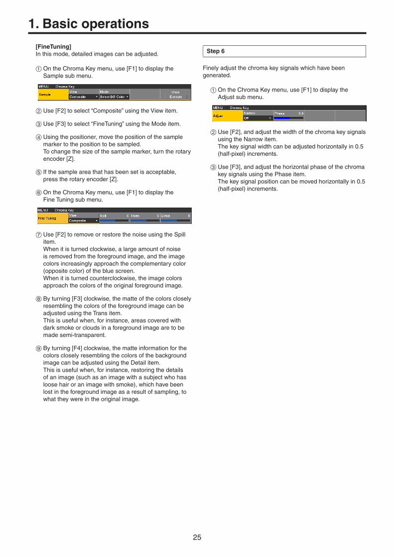
[FineTuning]Inthismode,detailedimagescanbeadjusted.
1OntheChromaKeymenu,use[F1]todisplaytheSamplesubmenu.
2Use[F2]toselect“Composite”usingtheViewitem.
3Use[F3]toselect“FineTuning”usingtheModeitem.
4Usingthepositioner,movethepositionofthesamplemarkertothepositiontobesampled.Tochangethesizeofthesamplemarker,turntherotaryencoder[Z].
5Ifthesampleareathathasbeensetisacceptable,presstherotaryencoder[Z].
6OntheChromaKeymenu,use[F1]todisplaytheFineTuningsubmenu.
7Use[F2]toremoveorrestorethenoiseusingtheSpillitem.Whenitisturnedclockwise,alargeamountofnoiseisremovedfromtheforegroundimage,andtheimagecolorsincreasinglyapproachthecomplementarycolor(oppositecolor)ofthebluescreen.Whenitisturnedcounterclockwise,theimagecolorsapproachthecolorsoftheoriginalforegroundimage.
8Byturning[F3]clockwise,thematteofthecolorscloselyresemblingthecolorsoftheforegroundimagecanbeadjustedusingtheTransitem.Thisisusefulwhen,forinstance,areascoveredwithdarksmokeorcloudsinaforegroundimagearetobemadesemi-transparent.
9Byturning[F4]clockwise,thematteinformationforthecolorscloselyresemblingthecolorsofthebackgroundimagecanbeadjustedusingtheDetailitem.Thisisusefulwhen,forinstance,restoringthedetailsofanimage(suchasanimagewithasubjectwhohasloosehairoranimagewithsmoke),whichhavebeenlostintheforegroundimageasaresultofsampling,towhattheywereintheoriginalimage.
Step 6
Finelyadjustthechromakeysignalswhichhavebeengenerated.
1OntheChromaKeymenu,use[F1]todisplaytheAdjustsubmenu.
2Use[F2],andadjustthewidthofthechromakeysignalsusingtheNarrowitem.Thekeysignalwidthcanbeadjustedhorizontallyin0.5(half-pixel)increments.
3Use[F3],andadjustthehorizontalphaseofthechromakeysignalsusingthePhaseitem.Thekeysignalpositioncanbemovedhorizontallyin0.5(half-pixel)increments.

26
1. Basic operations
1-3-7. Key decorationsAborder,shadoworotheredgecanbeaddedtothekey.
Setting the key edge
1Pressthekbuttontolightitsindicator,anddisplaytheKeymenu.
2Use[F1]todisplaytheEdge1submenu.
3Use[F2]toselecttheedgetype.
Off Anedgeisnotadded.
Border Aborderisaddedaroundtheentireedge.
Drop Adiagonalborderisadded.
Shadow Ashadowisadded.
Outline Anoutline(onlyaborderwithnofill)isadded.
Border Drop
OutlineShadow
4Use[F3]tosettheedgewidth.
5Use[F4]tosetthedirection(in45-degreeincrements)inwhich“Drop”and“Shadow”willbeadded.
(Top)
(Bottom)
(Right)(Left)
225180 270
135 315
4590 0
6Use[F5]tosetthedarkness(Density)oftheedges.
Selecting the Edge Fill settings
Materialstobeinsertedasedgescanbeset.
1OntheKeymenu,use[F1]todisplaytheEdge2submenu.
2Use[F2]toselecttheedgematerialusingtheEdgeFillitems.
Color ThecolorsetusingEdgeColorisused.
CBGD1Thecolorbackgroundisused.
CBGD2
Still1 Thestillimagevideomemory(Still1)isused.
Still2 Thestillimagevideomemory(Still2)isused.
Clip1 Themovingimagevideomemory(Clip1)isused.
Clip2 Themovingimagevideomemory(Clip2)isused.
Setting the edge color
1OntheKeymenu,use[F1]todisplaytheEdgeColorsubmenu.
2Use[F2],[F3]and[F4]toadjusttheHue,SatandLumoftheedgecolor.
w To call the preset color
Use[F5]toselectthepresetcolorusingtheLoaditem,andpressthe[F5].
When[F5]ispressed,whathasbeensetsofariscanceledandreplacedwiththepresetcolorvalues.
Tosavethevaluesthatweresetbeforecallingthepresetcolor,referto“1-10.Memory”.

27
1. Basic operations
1-3-8. Masking the key signalsThesestepsaretakentomaskthekeysignalsusingthemasksignaloftheboxpattern.
1Pressthekbuttontolightitsindicator,anddisplaytheKeymenu.
2Use[F1]todisplaytheMasksubmenu.
3Use[F2],andselectthemaskingmethodusingtheMaskitem.
Off Thekeysignalsarenotmasked.
Manual TheareathatissetusingtheMaskAdjustsubmenuismasked.
4:3 Thesignalsaremaskedtothe4:3aspectratio.
4Use[F3]tosetwhethertoinvertthemasksignalusingtheInvertitem.
On Themasksignalisinverted.
Off Themasksignalisnotinverted.
5Use[F1]todisplaytheMaskAdjustsubmenu.
6Use[F2]to[F5]tosettheareatobemasked.
Operation/Parameter
Description of setting
Setting range/Initial value
F2/Left
Keyleftposition−50.00to50.00/−25.00
F3/Top
Keytopposition−50.00to50.00/
25.00
F4/Bottom
Keybottomposition−50.00to50.00/−25.00
F5/Right
Keyrightposition−50.00to50.00/
25.00
TheLeftsettingcannotexceedtheRightsetting(andviceversa)and,similarly,theTopsettingcannotexceedtheBottomsetting(andviceversa).
<Key mask setting>(figureshowsthedefaultvalues)
0
50
-50 500-50
TOP (25)
BOTTOM (-25)
(25)RIGHT
(-25)LEFT
Areamasked
Areawherethekeysignaliseffective
Videosignalrange

28
1. Basic operations
1-3-9. Flying keyUsingDVEeffects,thiskeyenablesthekeysignalsthathavebeeninputtobemoved,expandedorcontracted.Inorderfortheflyingkeytotakeeffect,select“SQ2:8”asthekeytransition.Referto“1-2-1.Selectingthewipepattern”.
Whenthekeytransitionisexecuted,thekeysarecombinedbythekeysignalssetusingtheflyingkeymenu.(ThetransitioneffectisfixedatMIX.)SincetheflyingkeyusesDVEeffects,theimageisdelayedbyoneframe.
1Pressthekbuttontolightitsindicator,anddisplaytheKeymenu.
2Use[F1]todisplaytheFlyingKeysubmenu.
3Use[F2]tosettheXcoordinateofthekeysignalusingtheX-Positem.
4Use[F3]tosettheYcoordinateofthekeysignalusingtheY-Positem.
5Use[F4]tosetthekeysignalchangesize(max.400:400%)usingtheSizeitem.
Keysignal Whencombinedusingtheflyingkey
ABC ABC
InordertoaddtheedgeofthekeybeforetheDVEeffect,thethicknessoftheedgeisalsochangedwhenthesizeischanged.
PinP combinations using the flying key
When“Full”isselectedusingtheTypeitemin“1-3-1.Selectingthekeytype”,PinPcombinationscanbeperformedusingtheflyingkey.(Atthispointintime,theClipitemandGainitemcannotbesetontheAdjustsubmenu.)
Withthefullkey,theimageonthefullscreenservesasthekeysourcesignalsoanedgewillnotbeaddedunlessafurtherstepistaken.Toaddanedge,maskthekeysignalssothatthekeysourcesignalsaremadesmallerthantheentirescreen.Fordetailsonmasking,referto“1-3-8.Maskingthekey
signals”.
1-3-10. Setting the priorityTherelativepositionsoftheimageswhenkey,PinP1andPinP2imagesaretobesuperimposedontooneanothercanbeset.
1Pressthekbuttontolightitsindicator,anddisplaytheKeymenu.
2Use[F1]todisplaytheKeyPrioritysubmenu.
3Use[F2]to[F4]tosettherelativepositionsusingtheLowitem,MiddleitemandHighitem.
Low Thisisusedtosettheimagetobeplacedatthebottom.
Middle Thisisusedtosettheimagetobeplacedinthemiddle.
High Thisisusedtosettheimagetobeplacedatthetop.
Low: Key
Middle: PinP1
High: PinP2

29
1. Basic operations
1-4. PinP (picture in picture)Anotherimagecanbecombinedwiththebackgroundimage.ThisunitsupportstwoPinPchannels.
1-4-1. Selecting the PinP channel and material
Pressthe[PinP1]button(or[PinP2]button)amongtheAUXbusselectorbuttons.Whenthe[PinP1]button(or[PinP2]button)islit,thePinP1menu(orPinP2menu)isdisplayedonthebuilt-indisplay.ThestateinwhichthePinP1materials(orPinP2materials)areselectedisnowestablishedfortheAUXbuscrosspointbuttons.
TheselectedAUXbuscrosspointbuttonlightsinamber.(ItwilllightinrediftheselectedsignalisaPGMoutputsignal.)
AMBER : FILL / GREEN : SOURCE
KEY PinP1 PinP2 DSK AUX1 AUX2 AUX3 AUX4 DISP MV
AUX BUS DELEGATION
AUX
AUX/DISP SOURCE
SHIFT
PGMPVW
1-4-2. Transition between PinP materialsWhenaPinPbusmaterialhasbeenselected,theeffecttobeproducedwhenimagesareswitchedcanbeexecutedasaMIXtransition.(Bustransitionfunction)p WhenonematerialsettotheDotbyDotmodeand
anothermaterialhavebeenswitched,cutswitchingwheretheimageschangeinaninstantisperformed.
1Pressthetbuttontolightitsindicator,anddisplaytheTimemenu.
2Use[F1]todisplaythePinP1BUSTranssubmenu(orPinP2BUSTranssubmenu).
3Use[F3]and[F4]tosetthetransitiontime.
4Use[F5]tosetenableordisableforthebustransitionfunction.
Enable Enable
Disable Disable
Whilethetransitionisunderway,theindicatorofthetransitionsourcebuttonlights,andtheindicatorofthetransitiondestinationbuttonblinks.Whenthetransitioniscompleted,theindicatorofthetransitionsourcebuttongoesoff,andtheindicatorofthetransitiondestinationbuttonlights.Whenanothersignalhasbeenselectedwhileatransitionisunderway,theprocessingforthetransitionwillcontinuefromtheinterimpoint.

30
1. Basic operations
1-4-3. Selecting ShapeSquare,Circle,Heart,StarorFlowercanbeselectedastheshapeusedforcombiningPinPimages.
1Pressthepbuttontolightitsindicator,anddisplaythePinP1menu(orPinP2menu).
2Use[F1]todisplaythePinPsubmenu.
3Use[F2]and,usingtheShapeitem,selecttheshapeusedforcombiningimages.
4Use[F3]toadjustthetransmissivity(darkness)applyingwhentheimagesarecombinedusingtheDensityitem.
1-4-4. PinP previewSelectwhethertooutputthePinP1andPinP2previewimagestothepreviewoutput.
1OnthePinPsubmenu,use[F5]tosetthePVWitem.
On AnimagewiththePinP1(orPinP2)effectaddedisoutputtothepreviewoutput.
Off AnimagewithoutthePinP1(orPinP2)effectaddedisoutputtothepreviewoutput.
ThePVWOnandOffsettingscanbeallocatedtotheuserbuttons.When“PinP1PVW”(or“PinP2PVW”)isassignedtoauserbutton,thePinP1image(orPinP2image)previewoutputisturnedonoroffeverytimetheuserbuttonispressed.When“PinPPVW”isassignedtoauserbutton,thePinP1imageandPinP2imagepreviewoutputsaresimultaneouslyturnedonoroffeverytimetheuserbuttonispressed.Referto“3-3-1.Settingtheuserbuttons”.
1-4-5. PinP transitions1Setthetransitiontime.
OntheTimemenu,use[F1]todisplaythePinP1submenu(orPinP2submenu).Aswithbackgroundtransitions,setthetransitiontime.Referto“1-1-6.Autotransition”.
2Whenthe[PinP1ON]button(or[PinP2ON]button)inthetransitionareaispressed,thePinP1image(orPinP2image)transitions(fadesin)forthelengthofthetransitiontimethathasbeenset.Duringfade-in,the[PinP1ON]button(or[PinP2ON]button)blinksinred,andwhenthetransitioniscompleted,itlightsinred.Whenthe[PinP1ON]button(or[PinP2ON]button)ispressedafterfade-iniscompleted,thePinP1image(orPinP2image)transitions(fadesout).Duringfade-out,the[PinP1ON]button(or[PinP2ON]button)lightsinred,andwhenthetransitioniscompleted,itgoesoff.Ifthe[PinP1ON]button(or[PinP2ON]button)ispressedatanypointduringatransition,thedirectionofthetransitionisreversed.

31
1. Basic operations
1-4-6. PinP adjustments
Adjusting the PinP position and size
WhilethePinPmenuisselected,adjusttheXandYcoordinatesusingthepositionerinthepositionerarea,andadjustthesizeusingtherotaryencoder[Z].Alternatively,thesettingscanbeperformedonthemenus.
1Pressthepbuttontolightitsindicator,anddisplaythePinP1menu(orPinP2menu).
2Use[F1]todisplaythePositionsubmenu.
3Eitheroperatethepositionerandtherotaryencoder[Z]oruse[F2],[F3]and[F4]tosettheXandYcoordinatesandthesizeusingtheX-Pos,Y-PosandSizeitems.
Select the dot by dot mode
WhenthesystemissettotheHDmodeandanSDformatimageistobeusedforthePinPmaterial,theimagescanbecombinedinthedotbydotmode(actual-sizeimages).Inthismode,theSDformatimagewillnotbeup-convertedsoimagedeteriorationcanbeprevented.p When“100.00”hasbeenselectedastheSizeitem
settingonthePositionsubmenu,thesizeusedforthecombinationwillbethesamenumberoflinesastheSDformatimage.
1Presstheibuttontolightitsindicator,anddisplaytheInputmenu.
2Use[F2]toselectthesignalsforinputtingthePinPmaterialusingtheSelectitem.
3Use[F1]todisplaytheFSsubmenu.
4Use[F3]toselect“DotbyDot”usingtheModeitem,andpressthe[F3]toentertheselection.
SD HD
SDPinPmaterial
PinPcombinedimage

32
1. Basic operations
1-4-7. Linking PinP1 and PinP2ThePinP1andPinP2imagesperformasymmetricaloperationfortheaxiswhosecoordinatesandrotationanglehavebeenset.TheimageservingasthereferenceisthePinPimageofthemenubeingoperated.
Setting the priority
Settherelativepositionsoftheimageswhenkey,PinP1andPinP2imagesaretobesuperimposedontooneanother.Referto“1-3-10.Settingthepriority”.
Linking PinP1 and PinP2
1Pressthepbuttontolightitsindicator,anddisplaythePinP1menu(orPinP2menu).
2Use[F1]todisplaytheSyncsubmenu.
3Use[F2]toselectthepositionthatwillserveasthereferenceusingtheSymmetryitem.TheimageservingasthereferenceisthePinPimageofthemenubeingoperated.
When “X” has been selected as the Symmetry setting
ThecoordinatesandrotationanglearemadesymmetricaltotheXaxis.
When “Y” has been selected as the Symmetry setting
ThecoordinatesandrotationanglearemadesymmetricaltotheYaxis.
When “Center” has been selected as the Symmetry setting
Thecoordinatesandrotationanglearemadesymmetricaltothecenter.
Copying the settings
ThePinP1settingscanbecopiedtoPinP2and,similarly,thePinP2settingscanbecopiedtoPinP1.
1OnthePinP1menu(orPinP2menu),use[F1]todisplaytheSyncsubmenu.
2Use[F2]toselect“Off”usingtheSymmetryitem.
3When[F5]ispressed,thePinP1(orPinP2)settingsarecopiedandsetinPinP2(orPinP1).
Thefollowingsettingsarenotcopied. Trimsubmenuitems
Note

33
1. Basic operations
1-4-8. PinP decorationsAborderorsofteffectcanbeaddedtoPinP.
1Pressthepbuttontolightitsindicator,anddisplaythePinP1menu(orPinP2menu).
2Use[F1]todisplaytheBordersubmenu.
3Use[F2]tosetOn(orOff)fortheborderusingtheBorderitem.
4Use[F3]tosetthewidthoftheborderusingtheWidthitem.
5Use[F4]tosettheamountofsofteffectusingtheSoftitem.ThesofteffectisOFFif0.0isset.When“On”hasbeenselectedastheBorderitemsetting,theratioofthesofteffecttotheborderwidthisindicatedastheamountofsofteffect.WhenonlythesofteffectistobeaddedtoPinP,select“Off”astheBorderitemsetting.
6Use[F5]tosetthechangeintheborderwidthusingtheModeitem.
Fix Theborderwidthiskeptconstant.
Variable TheborderwidthchangestosuitthePinPsize.
Setting the border color
1OnthePinP1menu(orPinP2menu),use[F1]todisplaytheBorderColorsubmenu.
2Use[F2],[F3]and[F4]toadjusttheHue,SatandLumofthebordercolor.
w To call the preset color
Use[F5]toselectthepresetcolorusingtheLoaditem,andpressthe[F5].
When[F5]ispressed,whathasbeensetsofariscanceledandreplacedwiththepresetcolorvalues. Tosavethevaluesthatweresetbeforecallingthepresetcolor,referto“1-10.Memory”.
34
1. Basic operations
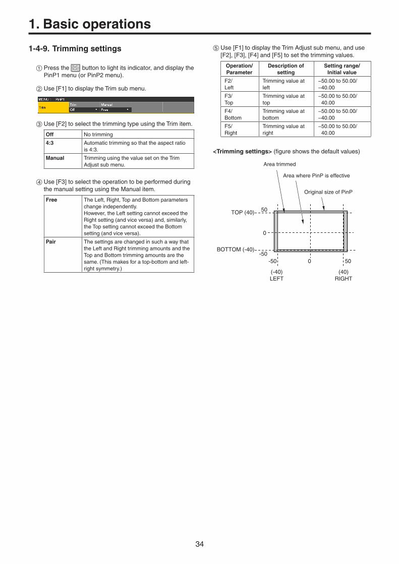
1-4-9. Trimming settings
1Pressthepbuttontolightitsindicator,anddisplaythePinP1menu(orPinP2menu).
2Use[F1]todisplaytheTrimsubmenu.
3Use[F2]toselectthetrimmingtypeusingtheTrimitem.
Off Notrimming
4:3 Automatictrimmingsothattheaspectratiois4:3.
Manual TrimmingusingthevaluesetontheTrimAdjustsubmenu.
4Use[F3]toselecttheoperationtobeperformedduringthemanualsettingusingtheManualitem.
Free TheLeft,Right,TopandBottomparameterschangeindependently.However,theLeftsettingcannotexceedtheRightsetting(andviceversa)and,similarly,theTopsettingcannotexceedtheBottomsetting(andviceversa).
Pair ThesettingsarechangedinsuchawaythattheLeftandRighttrimmingamountsandtheTopandBottomtrimmingamountsarethesame.(Thismakesforatop-bottomandleft-rightsymmetry.)
5Use[F1]todisplaytheTrimAdjustsubmenu,anduse[F2],[F3],[F4]and[F5]tosetthetrimmingvalues.
Operation/Parameter
Description of setting
Setting range/Initial value
F2/Left
Trimmingvalueatleft
−50.00to50.00/−40.00
F3/Top
Trimmingvalueattop
−50.00to50.00/40.00
F4/Bottom
Trimmingvalueatbottom
−50.00to50.00/−40.00
F5/Right
Trimmingvalueatright
−50.00to50.00/40.00
<Trimming settings>(figureshowsthedefaultvalues)
0
50
-50500-50
TOP (40)
BOTTOM (-40)
(-40)LEFT
(40)RIGHT
Areatrimmed
AreawherePinPiseffective
OriginalsizeofPinP

35
1. Basic operations
1-5. DSK (downstream key)Charactersorotherimagescanbecombinedwiththebackgroundimage.
1-5-1. Selecting the DSK type
1Pressthedbuttontolightitsindicator,anddisplaytheDSKmenu.
2Use[F1]todisplaytheDSKsubmenu.
3Use[F2]toselecttheTypeitem.
Lum (luminance key/ self key)
Thisisforcreatingthekeysignalsfromtheluminancecomponentofthekeyfillsignal.
Linear (linear key/ EXT key)
Thisisforcreatingthekeysignalsfromtheluminancecomponentofthekeysourcesignal.Itisusedwhenthekeysourcesignalandkeyfillsignalaredifferent.
Sincetheluminancekeyisoperatedasaselfkey,thekeyfillsignalsareusedasthekeysourcesignals.Whentheluminancekeyhasbeenselectedasthedownstreamkeytype,thekeysignalswillremainunchangedevenwhenthekeysourcesignalsareswitched.
Whenusingthelinearkey,usematerialwithablackbackgroundandwhitecharactersorshapetobecombinedbythekeyasthekeysourcesignal.Materialwhichisnotblackandwhitemaynotbecombinedclearly.Materialwithawhitebackgroundandblackcharacters,etc.canbereversedusingthekeyinvertfunctionforuse.
4Whentheluminancekeyhasbeenselected,thechromacomponentscanbecontainedinthekeysignalsgeneratedinviewofthefactthatitisusedasaselfkey.(Thisisnotappliedtothelinearkey.)Use[F3]toselectthesettingusingtheLumKeyitem.
Chroma On Inadditiontotheluminancecomponents,thechromacomponentsarealsofactoredinwhengeneratingthekeysignals.Usethissettingifcolorswithlowluminancecomponentsareusedforthekeysignals(when,forinstance,bluecharactersaretoberemoved).
Chroma Off Thekeysignalsaregeneratedonlyfromtheluminancecomponents.
5Use[F4]toselectthefilltypeusingtheFillitem.
Bus Thebussignalisusedforthekeyfillsignal.
Matte Theinternalfillmatteisusedforthekeyfillsignal.
Setting the fill matte color
1OntheDSKmenu,use[F1]todisplaytheFillMattesubmenu.
2Use[F2],[F3]and[F4]toadjusttheHue,SatandLumofthefillmatte.
w To call the preset color
Use[F5]toselectthepresetcolorusingtheLoaditem,andpressthe[F5].
When[F5]ispressed,whathasbeensetsofariscanceledandreplacedwiththepresetcolorvalues.
Tosavethevaluesthatweresetbeforecallingthepresetcolor,referto“1-10.Memory”.

36
1. Basic operations
1-5-2. Selecting the DSK material
Selecting the DSK fill signal and DSK source signal
Pressthe[DSK]buttonintheAUXbusselectionareatoswitchtheselectionoftheDSKfillsignal(indicatorlightsinamber)andDSKsourcesignal(indicatorlightsingreen).
<Selecting the DSK fill signal>
Whiletheindicatorofthe[DSK]buttonislitinamber,pressoneoftheAUXbuscrosspointbuttons1to12toselecttheDSKfillsignal.TheindicatoroftheselectedAUXbuscrosspointbuttonlightsinamber.(ItlightsinrediftheselectedsignalisbeingoutputfromthePGMconnector.)
AMBER : FILL / GREEN : SOURCE
KEY PinP1 PinP2 DSK AUX1 AUX2 AUX3 AUX4 DISP MV
AUX BUS DELEGATION
AUX
AUX/DISP SOURCE
SHIFT
PGMPVW
Lightinginamber
<Selecting the DSK source signal>
Whiletheindicatorofthe[DSK]buttonislitingreen,pressoneoftheAUXbuscrosspointbuttons1to12toselecttheDSKsourcesignal.TheindicatoroftheselectedAUXbuscrosspointbuttonlightsingreen.(ItlightsinrediftheselectedsignalisbeingoutputfromthePGMconnector.)Sincetheluminancekeyisoperatedasaselfkey,thekeyfillsignalsareusedasthekeysourcesignals.Whentheluminancekeyhasbeenselectedasthedownstreamkeytype,thekeysignalswillremainunchangedevenwhenthekeysourcesignalsareswitched.
AMBER : FILL / GREEN : SOURCE
KEY PinP1 PinP2 DSK AUX1 AUX2 AUX3 AUX4 DISP MV
AUX BUS DELEGATION
AUX
AUX/DISP SOURCE
SHIFT
PGMPVW
Lightingingreen
1-5-3. DSK transitions1Setthetransitiontime.
Pressthetbuttontolightitsindicator,anddisplaytheTimemenu.
2Use[F1]todisplaytheDSKsubmenu.Aswithbackgroundtransitions,setthetransitiontime.Referto“1-1-6.Autotransition”.
3Whenthe[DSKON]buttoninthetransitionareaispressed,theDSKimageiscombined(fadesin)forthelengthofthetransitiontimethathasbeenset.
Duringfade-in,the[DSKON]buttonblinksinred,andwhenthetransitioniscompleted,itlightsinred.Whenthe[DSKON]buttonispressedafterfade-iniscompleted,theDSKimagetransitions(fadesout).Duringfade-out,the[DSKON]buttonlightsinred,andwhenthetransition(fade-out)iscompleted,itgoesoff.Ifthe[DSKON]buttonispressedatanypointduringatransition,thedirectionofthetransitionisreversed.

37
1. Basic operations
1-5-4. DSK previewSelectwhethertooutputtheDSKpreviewimagetothepreviewoutput.
1Pressthedbuttontolightitsindicator,anddisplaytheDSKmenu.
2Use[F1]todisplaytheDSKsubmenu.
3Use[F5]tosetthePVWitem.
On AnimagewiththeDSKeffectaddedisoutputtothepreviewoutput.
Off AnimagewithouttheDSKeffectaddedisoutputtothepreviewoutput.
ThePVWOnandOffsettingscanbeallocatedtotheuserbuttons.Referto“3-3-1.Settingtheuserbuttons”.
1-5-5. DSK adjustmentsTheDSKdefinitioncanbeadjusted.
1Pressthedbuttontolightitsindicator,anddisplaytheDSKmenu.
2Use[F1]todisplaytheAdjustsubmenu.
3Use[F2],[F3]and[F4]toadjusttheDSK(downstreamkey)definition.
4Use[F5]tosetkeyinvert.If“On”isset,thekeysignalsgeneratedinternallyareinverted.
Operation/Parameter
Description of setting Setting range
F2/Clip
Referencelevelforgeneratingkeysignals
0.0to108.0
F3/Gain
Keyamplitude 0.0to200.0
F4/Density
Keydensity 0.0to100.0
F5/Invert
Keysignalinversion On,Off

38
1. Basic operations
1-5-6. DSK decorationsAborder,shadoworothertypeofedgecanbeaddedtoDSK.
Setting the edge
1Pressthedbuttontolightitsindicator,anddisplaytheDSKmenu.
2Use[F1]todisplaytheEdge1submenu.
3Use[F2]toselecttheedgetype.
Off Anedgeisnotadded.
Border Aborderisaddedaroundtheentireedge.
Drop Adiagonalborderisadded.
Shadow Ashadowisadded.
Outline Anoutline(onlyaborderwithnofill)isadded.
Border Drop
OutlineShadow
4Use[F3]tosettheedgewidth.
5Use[F4]tosetthedirection(in45-degreeincrements)inwhich“Drop”and“Shadow”willbeadded.
(Top)
(Bottom)
(Right)(Left)
225180 270
135 315
4590 0
6Use[F5]tosetthedarkness(Density)oftheedges.
Setting Edge Fill
Materialstobeinsertedasedgescanbeset.
1OntheDSKmenu,use[F1]todisplaytheEdge2submenu.
2Use[F2]toselecttheedgematerialusingtheEdgeFillitem.
Color ThecolorsetusingEdgeColorisused.
CBGD1Thecolorbackgroundisused.
CBGD2
Still1 Thestillimagevideomemory(Still1)isused.
Still2 Thestillimagevideomemory(Still2)isused.
Clip1 Themovingimagevideomemory(Clip1)isused.
Clip2 Themovingimagevideomemory(Clip2)isused.
Setting the edge color
1OntheDSKmenu,use[F1]todisplaytheEdgeColorsubmenu.
2Use[F2],[F3]and[F4]toadjusttheHue,SatandLumoftheedgecolor.
w To call the preset color
Use[F5]toselectthepresetcolorusingtheLoaditem,andpressthe[F5].
When[F5]ispressed,whathasbeensetsofariscanceledandreplacedwiththepresetcolorvalues.
Tosavethevaluesthatweresetbeforecallingthepresetcolor,referto“1-10.Memory”.

39
1. Basic operations
1-5-7. Masking the DSK signalsThesestepsaretakentomasktheDSKsignalsusingthemasksignaloftheboxpattern.
1Pressthedbuttontolightitsindicator,anddisplaytheDSKmenu.
2Use[F1]todisplaytheMasksubmenu.
3Use[F2],andselectthemaskingmethodusingtheMaskitem.
Off TheDSKsignalsarenotmasked.
Manual TheareathatissetusingtheMaskAdjustsubmenuismasked.
4:3 Thesignalsaremaskedtothe4:3aspectratio.
4Use[F3]tosetwhethertoinvertthemasksignalusingtheInvertitem.
On Themasksignalisinverted.
Off Themasksignalisnotinverted.
5Use[F1]todisplaytheMaskAdjustsubmenu.
6Use[F2]to[F5]tosettheareatobemasked.
Operation/Parameter
Description of setting
Setting range/Initial value
F2/Left
DSKleftposition−50.00to50.00/−25.00
F3/Top
DSKtopposition−50.00to50.00/
25.00
F4/Bottom
DSKbottomposition−50.00to50.00/−25.00
F5/Right
DSKrightposition−50.00to50.00/
25.00
TheLeftsettingcannotexceedtheRightsetting(andviceversa)and,similarly,theTopsettingcannotexceedtheBottomsetting(andviceversa).
<DSK mask setting>(figureshowsthedefaultvalues)
0
50
-50 500-50
TOP (25)
BOTTOM (-25)
(25)RIGHT
(-25)LEFT
Areamasked
AreawheretheDSKsignaliseffective
Videosignalrange

40
1. Basic operations
1-6. Key LinkThisfunctionmakesitpossibletolinkthe“On”or“Off”settingofthe[DSKON]buttonandPinPbuttons([PinP1ON]and[PinP2ON])withthe“On”or“Off”(buttonindicatorlightsoroff)ofthe[KEYON]button.
CUT AUTO
MIX
MIX WIPE
N/R R
BKGD KEY KEYON
FTBON
PinP1ON
PinP2ON
DSKON
WIPE DIRECTION
WIPE
MIX
WIPE
1Pressthesbuttontolightitsindicator,anddisplaytheConfigmenu.
2Use[F1]todisplaytheOperatesubmenu.
3Use[F3]toselectthelinkoperationusingtheKeyLinkitem.
Off Thisreleasesthelinkwiththe[KEYON]button.
DSK Thislinksthe“On”or“Off”settingofthe[DSKON]buttonwiththe“On”or“Off”settingofthe[KEYON]button.
Whenthe[DSKON]buttonis“On”,the[DSKON]buttonremains“On”evenwhenthe[KEYON]buttonissetto“On”.
Whenthe[DSKON]buttonis“Off”,the[DSKON]buttonremains“Off”evenwhenthe[KEYON]buttonissetto“Off”.
Thereisnolinkwiththeautotransitionoperationinitiatedbysettingthe[AUTO]buttonto“On”whenthe[KEY]buttonhasbeenselected.
PinP1 Thislinksthe“On”or“Off”settingofthe[PinP1ON]buttonwiththe“On”or“Off”settingofthe[KEYON]button.
Whenthe[PinP1ON]buttonis“On”,the[PinP1ON]buttonremains“On”evenwhenthe[KEYON]buttonissetto“On”.
Whenthe[PinP1ON]buttonis“Off”,the[PinP1ON]buttonremains“Off”evenwhenthe[KEYON]buttonissetto“Off”.
Thereisnolinkwiththeautotransitionoperationinitiatedbysettingthe[AUTO]buttonto“On”whenthe[KEY]buttonhasbeenselected.
PinP2 Thislinksthe“On”or“Off”settingofthe[PinP2ON]buttonwiththe“On”or“Off”settingofthe[KEYON]button.
Whenthe[PinP2ON]buttonis“On”,the[PinP2ON]buttonremains“On”evenwhenthe[KEYON]buttonissetto“On”.
Whenthe[PinP2ON]buttonis“Off”,the[PinP2ON]buttonremains“Off”evenwhenthe[KEYON]buttonissetto“Off”.
Thereisnolinkwiththeautotransitionoperationinitiatedbysettingthe[AUTO]buttonto“On”whenthe[KEY]buttonhasbeenselected.
PinP1/2 Thislinksthe“On”or“Off”settingsofthe[PinP1ON]buttonand[PinP2ON]buttonwiththe“On”or“Off”settingofthe[KEYON]button.Whenthe[PinP1ON]buttonand
[PinP2ON]buttonare“On”,the[PinP1ON]buttonand[PinP2ON]buttonremain“On”evenwhenthe[KEYON]buttonissetto“On”.Whenthe[PinP1ON]buttonand
[PinP2ON]buttonare“Off”,the[PinP1ON]buttonand[PinP2ON]buttonremain“Off”evenwhenthe[KEYON]buttonissetto“Off”.Thereisnolinkwiththeautotransition
operationinitiatedbysettingthe[AUTO]buttonto“On”whenthe[KEY]buttonhasbeenselected.

41
1. Basic operations
1-7. FTB (Fade to Black)Theusercanfadeoutfromaprogramimagetotheblackscreenorfadeintoaprogramimagefromablackscreen.
1Setthedurationofthetransition.Pressthetbuttontolightitsindicator,anddisplaytheTimemenu.
2Use[F1]todisplaytheFTBsubmenu.Aswithabackgroundtransition,setthetransitiontime.Referto“1-1-6.Autotransition”.
CUT AUTO
MIX
MIX WIPE
N/R R
BKGD KEY KEYON
FTBON
PinP1ON
PinP2ON
DSKON
WIPE DIRECTION
WIPE
MIX
WIPE
3Whenthe[FTBON]buttoninthetransitionareaispressed,fade-outtotheblackscreenisinitiatedforthelengthofthetransitiontimethathasbeenset.
Duringfade-out,theindicatorofthe[FTBON]buttonblinksinred,anditlightsinredwhenthetransition(fade-out)iscompleted,andtheblackscreenisdisplayed.1Whenthe[FTBON]buttonispressedwiththeblackscreendisplayed,fade-intotheprogramimageisinitiated.Duringfade-in,theindicatorofthe[FTBON]buttonlightsinred,anditgoesoffwhenthetransition(fade-in)iscompleted.Ifthe[FTBON]buttonispressedatanypointduringatransition,thedirectionofthetransitionisreversed.
1: IntheFTBstatus,thecrosspointbuttonwhichisnormallylitinredlightsinamber.
Selecting the image
Theimagetobeusedforfadingoutcanbeselected.
1Pressthesbuttontolightitsindicator,anddisplaytheConfigmenu.
2Use[F1]todisplaytheAssignsubmenu.
3Use[F2]toselecttheimagetoappearwhenfadingoutusingtheFTBSourceitem.
Still1 Thestillimagevideomemory(Still1)isused.
Still2 Thestillimagevideomemory(Still2)isused.
Clip1 Themovingimagevideomemory(Clip1)isused.
Clip2 Themovingimagevideomemory(Clip2)isused.
CBGD1Thecolorbackgroundisused.
CBGD2
White Whitebackground
Black Blackbackground
Ifasettingotherthan“White”or“Black”hasbeenselectedusingtheFTBSourceitem,thecorrespondingcrosspointbuttonwilllightinredintheFTBstatus.

42
1. Basic operations
1-8. Internal color signalsThisunitsupportstwosetsofinternalcolorsignals.
1-8-1. Setting the color backgroundThecolorbackgroundtobeusedbythebuscanbeset.Twomethodsareavailable:underonemethodtheHue(hue),Sat(colorsaturation)andLum(luminance)areset,andundertheotherthe8presetcolors(white,yellow,cyan,green,magenta,red,blueandblack)arecalled.TheHue,SatandLumofthecalledcolorscanalsobeadjusted.
Adjusting the colors
1Pressthebbuttontolightitsindicator,anddisplaytheColorBackgroundmenu.
2Use[F1]todisplaytheCBGD1Mainsubmenu(orCBGD2Mainsubmenu).
3Use[F2],[F3]and[F4]toperformthecoloradjustments(Hue,SatandLum).
w To call the preset color
Use[F5]toselectthepresetcolorusingtheLoaditem,andpressthe[F5].
When[F5]ispressed,whathasbeensetsofariscanceledandreplacedwiththepresetcolorvalues. Tosavethevaluesthatweresetbeforecallingthepresetcolor,referto“1-10.Memory”.
1-8-2. Setting the Wash effectThegradationeffectforcolorbackgroundscanbeset.
Selecting the Wash effect and setting the colors
1Pressthebbuttontolightitsindicator,anddisplaytheColorBackgroundmenu.
2Use[F1]todisplaytheCBGD1Washsubmenu(orCBGD2Washsubmenu).
3Use[F2]tosettheWash(gradation)effectusingtheWashitem.
On Thegradationeffectisadded.
Off Thegradationeffectisnotadded.
4Use[F3]tosetthecoloroftheWash(gradation)effectusingtheColoritem.
Dual Adual-colorgradationeffectisadded.(Thisresultsinagradationoftwocolors,namely,theCBGD1MaincolorandtheCBGD1Subcolor.)
Rainbow Therainbowcolorgradationeffectisadded.
5When“Dual”hasbeenselected,use[F1]todisplaytheCBGD1Subsubmenu(orCBGD2Subsubmenu),andsetthesubcolor.
6Use[F2],[F3]and[F4]toadjustthecolors(Hue,SatandLum).

43
1. Basic operations
Adjusting the Wash waveforms
1OntheColorBackgroundmenu,use[F1]todisplaytheCBGD1Wavesubmenu(orCBGD2Wavesubmenu).
2Use[F2]toselectthegradationwaveformsusingthePatternitem.
Sine Sinewavesareselected.
Saw Sawtoothwavesareselected.
3Use[F3]toselectthegradationcycleusingtheCycleitem.
4Use[F4]toselectthegradationphaseusingthePhaseitem.
5Use[F5]toselectthegradationangleusingtheAngleitem.
Setting the Wash movements
1OntheColorBackgroundmenu,use[F1]todisplaytheCBGD1Movesubmenu(orCBGD2Movesubmenu).
2Use[F2]tosetthegradationmovementusingtheMoveitem.
Off Nomovementisset.
Roll Thegradationsarescrolled.
Rotation Thegradationsarerotated.
3Use[F3]tosetthemovementspeedusingtheSpeeditem.

44
1. Basic operations
1-9. Switching the AUX output
1-9-1. Selecting the AUX output materialsTheoutputsignalsoftheAUXbuses(AUX1toAUX4)canbeselected.
1Pressoneofthe[AUX1]to[AUX4]buttonsamongtheAUXbusselectorbuttons.Theselectedbuttonlightsinamber.
2PressoneoftheAUXbuscrosspointbuttons.Theselectedsignalisoutputtothepressed[AUX1]to[AUX4]button.
AMBER : FILL / GREEN : SOURCE
KEY PinP1 PinP2 DSK AUX1 AUX2 AUX3 AUX4 DISP MV
AUX BUS DELEGATION
AUX
AUX/DISP SOURCE
SHIFT
PGMPVW
ThebuttonwiththesignalsselectedbyAUX1lightsinamber.
<Signals that can be selected by the AUX bus>
Name of signal Description of signal
SDIIN1to8 SDIinputsignal1to8
DVIIN DVI-Dinputsignal
INPUTA1,INPUTA2,INPUTB1,INPUTB2
InputsignalA1,InputsignalA2,InputsignalB1,InputsignalB2
PGM Programvideosignal
PVW Previewvideosignal
CLN Cleansignal
MV Multiviewdisplayoutputsignal
KeyOut Keyoutputsignal
CBGD1,CBGD2 Colorbackground1,2
CBAR Colorbar
Still1,Still2 Videomemory(stillimage)1,2
Clip1,Clip2 Videomemory(movingimage)1,2
MEM-PVW Memorypreviewvideosignals
WhentheAUXbusforwhich“MV”hasbeenselectedisdisplayedonthesubscreenofthemultiviewdisplay,theimagesareloopedasiftwomirrorswerefacingeachother.
1-9-2. AUX1 transitionsTheMIXtransitionisexecutedwhentheoutputsignalsetforAUX1isswitched.
1Pressthe[AUX1]buttonoftheAUXbusselectorbuttons.TheselectedbuttonanditscorrespondingAUXbuscrosspointbuttonlightinamber.
2PresstheAUXbuscrosspointbuttonfortheoutputsignaltobeswitchedto.TheMIXtransitionisnowinitiatedforthelengthofthetransitiontimethatwassetusingtheTimemenu.Whilethetransitionisunderway,thetransitionsourceAUXbuttonlightsingreen,andthetransitiondestinationAUXbuttonblinksinamber.Assoonasthetransitioniscompleted,thetransitionsourceAUXbuttongoesoff,andthetransitiondestinationAUXbuttonlightsinamber.Furthermore,whenanothersignalisselectedatamidwaypointthroughatransition,thetransitionprocessingcontinuesfromthatmidwaypoint.
AMBER : FILL / GREEN : SOURCE
KEY PinP1 PinP2 DSK AUX1 AUX2 AUX3 AUX4 DISP MV
AUX BUS DELEGATION
PGMA
AUX
1/13 2/14 3/15 4/16 5/17 6/18 7/19 8/20 9/21 10/22 11/23 12/24
AUX/DISP SOURCE
SHIFT
SHIFT
PGMPVW
Blinksinamber(whilethetransitionisunderway).
Lightsingreen.

45
1. Basic operations
1-9-3. Setting enable/disable for the AUX1 transition
TheAUX1transitiontimeandtransitionenable/disablecanbeset.
1Pressthetbuttontolightitsindicator,anddisplaytheTimemenu.
2Use[F1]todisplaytheAUX1BUSTranssubmenu.
3Whenthetransitiontimeistobesetinframeunits,use[F4]forthesetting.
4Whenthetransitiontimeistobesetinsecondunits,use[F3]tosetthesecondsand[F4]tosettheframes.
Anytimefrom0to999fcanbeset.Thetimewhichcanbesetwhensecondsareusedasthedisplayunitdiffersdependingonthesystemformat.59.94i: max.33s09f 59.94p: max.16s39f
50i: max.39s24f 50p: max.19s49f
24PsF: max.41s15f 23.98PsF: max.41s15f
5Use[F5]tosetenableordisableforthetransitionusingtheTransitionitem.
Enable Enable
Disable Disable
Whendisablehasbeensetforthetransition,theoutputsignalsareswitchedwithnotransitionwhentheoutputsignalssetinAUX1isswitched.

46
1. Basic operations
1-10. Memoryw Shot memoriesThebackgroundtransitionpattern,PinPsize,borderwidthandothervideoeffectscanberegisteredinthememoryandrecalled.Thememoryusedforthisisreferredtoasashotmemory.Bysettingeffectdissolve,itispossibletoensureasmoothchangeoftheswitchingfromthecurrentimagestotheimagesoroperationsregisteredintheshotmemory.
w Event memoriesAmultiplenumberofthevideoeffectswhichcanberegisteredintheshotmemorycanberegisteredandcontinuouslyplayedbackwhilethecurrenteventandnexteventareinterpolatedtoachievetheeffectofasmoothtransition.Agroupoftheseeventsarereferredtoasaneventmemory.Upto64eventscanberegisteredinoneeventmemory.p Whenoperationssuchasplayingareperformedoneventmemorieswithadifferentsystemformattowhentheevent
memorieswererecorded,theoperationswillnotbeperformedcorrectly.
Event1 Interpolation Event2
Event memory
Interpolation Event3
Uptoahundredshotmemoriesandahundredeventmemoriescanberegistered.Therelatedoperationsareperformedusingthenumberkeys.Page1topage10canbespecifiedforthepagenumbersofthememories.Numbers1to10canbespecifiedastherespectivememorynumbersforthespecifiedpagenumbers.
Selecting the memory numbers
1Pressthe[SHOTMEM]or[EVENTMEM]buttonofthememorytobeselected.
2PressthePbutton.ThePbuttonindicatorlightsup,andthemodeforspecifyingthememorypagenumberisestablished.Thenumberkeyofthecurrentlyselectedpagelightsinamber.Thenumberkeysofthepagenumbersinwhichmorethanonememoryisregisteredlightingreen.Theindicatorsofthenumberkeysofpagenumbersinwhichnomemorieshavebeenregisteredremainextinguished.
3Pressthenumberkey(1to10)ofthepagenumber.Whenthepagenumberisdetermined,thePbuttonindicatorgoesoff,andthemodeforspecifyingthememorynumberisestablished.Ifthepagenumberisnotgoingtobechanged,pressthePbuttontoturnoffitsindicatorinsteadofpressingthenumberkey.Thisestablishesthemodeforspecifyingthememorynumber.
4Pressthenumberkey(1to10)correspondingtothememorynumber.(Holddownthenumberkeywhenspecifyingamemorynumbertoregisterordeletethememory.)

47
1. Basic operations
1-10-1. Memory registration and recall items
Applicable bus Material selection Transition Pattern Menu
BKGD PGM/AbusPST/Bbus
FaderamountWipedirection
BKGDpatterns(MIX,WIPE)
BackgroundColorBackground
Key KeyFillbusKeySourcebus
FaderamountWipedirection
KEYpatterns(MIX,WIPE)
KeyChromaKey
PinP1 PinP1bus PinP1ON/OFF PinP1
PinP2 PinP2bus PinP2ON/OFF PinP2
1-10-2. Storing the settings in the memory (Store)Imagesandoperationstoberegisteredcanbesetandthenregisteredinthememories.
4INS
MENUINPUT
VMEM
BKGDPATT
KEYPATT
TAKEENTER
� / +PAGE
PLAY
REC
STOP
XPTDSBL
<
CLIP 1
STILL 1
MEMORY / WIPE PATTERN / 10 KEY<< TRIM OFF>>
CLIP 2
STILL 2
REV
TRIM OUT
TRIM IN
9PASTE
6MOD
3REV
CUNDO
8COPY
5DEL
2>
.>>
7NEW
1<
0/10<<
STORE
RECALL
EDIT
DEL
SHOTMEM
EVENTMEM
PLUGINMEM1
PLUGINMEM2
>
1Usingtheunit,settheimagesoroperationstobekeptinthememory.
2Pressthe[SHOTMEM]or[EVENTMEM]buttonofthememoryinwhichtheimagesoroperationsaretoberegistered.Dependingontheoperationthatwasperformedlast,the[STORE]button,[RECALL]button,[DEL]buttonor[EDIT]buttonlights.
3Selectthebus(BKGD,KEY,PinP1orPinP2)toberegisteredinthememory.FromtheShotMemorymenu(orEventMemorymenu),selecttheStoreSelectsubmenu,andthenselect“On”.Referto“1-10-1.Memoryregistrationandrecall
items”and“1-10-6.Selectingthebuseswhosesettingsaretoberegisteredandorplayedback”.
4WhenregisteringtheBKGD(PGM/AorPST/Bbus),KEYbus,PinP1busorPinP2bus,setwhetherthe“Materialselection”itemistobestored.FromtheShotMemorymenu(orEventMemorymenu),selecttheXPTDisablesubmenu,andthenselect“Off”.Referto“1-10-1.Memoryregistrationandrecallitems”and“1-10-7.Registeringthematerialselectionitems”.
5Pressthe[STORE]button.The[STORE]buttonindicatorlightsup,andtheoperationsofothermemorybuttons—[EVENTMEM](or[SHOTMEM]),[PLUGINMEM1]and[PLUGINMEM2]—nolongertakeeffect.
6PressthePbutton,andpressthenumberkey(1to10)correspondingtothepagenumber.
7Holddown(for2secondsorso)thenumberkey(1to10)correspondingtothenumberofthememorytoberegistered.Whentheregistrationiscompleted,thenumberkeycorrespondingtothememorynumberlightsingreen.
Thenumberkeyswhoseindicatorsarelitingreenhavememoriesalreadyregisteredinthem.Deletethememorycorrespondingtothenumberkeyconcerned,andregisterthenewmemory.
8Repeattheabovestepstoregisterotherkindsofsettingsinthememories.

48
1. Basic operations
1-10-3. Recalling the operations stored in the memory (Recall)
4INS
MENUINPUT
VMEM
BKGDPATT
KEYPATT
TAKEENTER
� / +PAGE
PLAY
REC
STOP
XPTDSBL
<
CLIP 1
STILL 1
MEMORY / WIPE PATTERN / 10 KEY<< TRIM OFF>>
CLIP 2
STILL 2
REV
TRIM OUT
TRIM IN
9PASTE
6MOD
3REV
CUNDO
8COPY
5DEL
2>
.>>
7NEW
1<
0/10<<
STORE
RECALL
EDIT
DEL
SHOTMEM
EVENTMEM
PLUGINMEM1
PLUGINMEM2
>
1Pressthe[SHOTMEM]or[EVENTMEM]buttonofthememorywhoseoperationsaretoberecalled.Dependingontheoperationthatwasperformedlast,the[STORE]button,[RECALL]button,[DEL]buttonor[EDIT]buttonlights.
2Selectthebus(BKGD,KEY,PinP1orPinP2)toberecalledfromthememory.FromtheShotMemorymenu(orEventMemorymenu),selecttheRecallSelectsubmenu,andthenselect“On”.Referto“1-10-6.Selectingthebuseswhosesettings
aretoberegisteredandorplayedback”.
3Whenselectingmaterialsusingthecrosspointbuttonsontheoperationpanelinsteadofusingtheregistered“Materialselection”itemmaterials,pressthe[XPTDSBL]buttontolightitsindicatorinred.Referto“1-10-1.Memoryregistrationandrecall
items”.
4Pressthe[RECALL]button.The[RECALL]buttonindicatorlightsup,andthenumberkeyinwhichthememoryisregisteredlightsingreen.Theoperationsofothermemorybuttons—[EVENTMEM](or[SHOTMEM]),[PLUGINMEM1]and[PLUGINMEM2]—nolongertakeeffect.
5PressthePbutton,andpressthenumberkey(1to10)correspondingtothepagenumber.
6Pressthenumberkey(1to10)correspondingtothenumberforthememorywhoseoperationsaretoberecalled.
Inthecaseofashotmemory,thevideoeffectsarerecalled,andplaybackstarts.Duringplayback,thenumberkeycorrespondingtothememorynumberblinksingreen.
Inthecaseofaneventmemory,theeventsarerecalled,andplaybackstarts.Duringplayback,thenumberkeycorrespondingtothememorynumberblinksingreen.IfthereisaPAUSEevent,playbackpausesatthatevent,andthenumberkeycorrespondingtothememorynumberblinksinamber.Eachtimethenumberkeycorrespondingtothememorynumberispressed,playbackorpauseisselectedalternately,andthisselectionisrepeated.
7Whenplaybackoftheeffectsoreventsintherecalledmemorynumberstarts,theCbuttonisenabled,anditsindicatorlightsup.Ifthisbuttonispressedduringplayback,playbackisterminated.

49
1. Basic operations
1-10-4. Memory previewThevideoeffectsintheshotmemoryoreventmemorycanbeoutputtotheprogramsignalsaftercheckingthemusingthememorypreviewbus(MEM-PVW).
1Presstheebuttontolightitsindicator,anddisplaytheShotMemorymenu(orEventMemorymenu).
2Use[F1]todisplaytheMEMPVWsubmenu.
3Use[F2]toselect“MEM-PVW”usingtheModeitem.
PGM Thevideoeffectsareoutputtotheprogramsignals.
MEM-PVW Thevideoeffectsarefirstoutputtothememorypreviewbus(MEM-PVW)andthenoutputtotheprogramsignals.
Output: MEM-PVW
Output: PGM
Mode: MEM-PVW
Mode: PGM
Shot memory/Event memory
Memory preview bus
Recalled
Program bus
Program images Preview images
Theresolutionoftheimagesoutputfromthememoriesislowerthannormal.
Memory recall
1Pressthe[SHOTMEM]or[EVENTMEM]buttonofthememorywhosevideoeffectsaretoberecalledtoselectthememory.(Pressthebuttonofthememorywiththevideoeffectsforpreviewplayback.)Dependingontheoperationperformedlast,theindicatorofthe[STORE]button,[RECALL]button,[DEL]buttonor[EDIT]buttonlightsup.
2Selectthebus(BKGD,Key,PinP1orPinP2)toberecalledfromthememory.FromtheShotMemorymenu(orEventMemorymenu),selecttheRecallSelectsubmenu,andthenselect“On”or“Off”.Referto“1-10-6.Selectingthebuseswhosesettings
aretoberegisteredandorplayedback”.
3Whenselectingmaterialsusingthecrosspointbuttonsontheoperationpanelinsteadofusingtheregistered“Materialselection”itemmaterials,pressthe[XPTDSBL]buttontolightitsindicatorinred.Referto“1-10-1.Memoryregistrationandrecall
items”.
4Pressthe[RECALL]button.The[RECALL]buttonindicatorlightsup,andthenumberkeyinwhichthememoryisregisteredlightsingreen.Theoperationsofothermemorybuttons—[EVENTMEM](or[SHOTMEM]),[PLUGINMEM1]and[PLUGINMEM2]—nolongertakeeffect.
5PressthePbutton,andpressthenumberkey(1to10)correspondingtothepagenumber.
Preview playback (output to the memory preview signals)
6Pressthenumberkey(1to10)correspondingtothenumberforthepreviewplaybackmemory.Thepreviewimagesareoutputtothememorypreviewbus(MEM-PVW).
Duringpreviewplayback,thenumberkeycorrespondingtothememorynumberblinksingreen.
IfthereisaPAUSEevent,previewplaybackpausesatthatevent,andthenumberkeycorrespondingtothememorynumberblinksinamber.Eachtimethenumberkeycorrespondingtothememorynumberispressed,previewplaybackorpauseisselectedalternately,andthisselectionisrepeated.
Whenpreviewplaybackiscompleted,theindicatorsofthenumberkeycorrespondingtothememorynumberand[TAKE/ENTER]buttonlightinamber.Ifthenumberkeycorrespondingtothememorynumberisnowpressedagain,previewplaybackresumes.

50
1. Basic operations
Program output (output to the program signals)
7Forprogramoutput,pressthe[TAKE/ENTER]button.
Duringoutput,the[TAKE/ENTER]buttonindicatorblinksingreen. InthecaseofaneventmemorywhichcontainsaPAUSEevent,theoutputpausesatthatevent,andthe[TAKE/ENTER]buttonindicatorblinksinamber.Toresumetheoutput,pressthe[TAKE/ENTER]button.Eachtimethe[TAKE/ENTER]buttonispressed,outputorpauseisselectedalternately,andthisselectionisrepeated.Whenoutputiscompleted,the[TAKE/ENTER]buttonindicatorslightsinamber.
8Whenprogramoutputisstarted,theCbuttontakeseffect,anditsindicatorlightsup.IftheCbuttonispressedduringoutput,playbackisterminated.
<Button lighting statuses>During preview playback
ButtonDuring
playbackPause Stop
Numberkeycorrespondingtomemorynumbers
Blinks(ingreen)
Blinks(inamber)
Lights(inamber)
T — —Lights
(inamber)
C — — —
During program output
Button During output Pause Stop
Numberkeycorrespondingtomemorynumbers
Blinks(ingreen)
Blinks(inamber)
Lights(inamber)
TBlinks
(ingreen)Blinks
(inamber)Lights
(inamber)
CLights
(inamber)— —
1-10-5. Deleting the operations stored in the memory (Delete)
4INS
MENUINPUT
VMEM
BKGDPATT
KEYPATT
TAKEENTER
� / +PAGE
PLAY
REC
STOP
XPTDSBL
<
CLIP 1
STILL 1
MEMORY / WIPE PATTERN / 10 KEY<< TRIM OFF>>
CLIP 2
STILL 2
REV
TRIM OUT
TRIM IN
9PASTE
6MOD
3REV
CUNDO
8COPY
5DEL
2>
.>>
7NEW
1<
0/10<<
STORE
RECALL
EDIT
DEL
SHOTMEM
EVENTMEM
PLUGINMEM1
PLUGINMEM2
>
1Pressthe[SHOTMEM]or[EVENTMEM]buttonofthememorywhoseoperationsaretobedeletedtoselectthememory.Theselectedbuttonlightsinamber.Dependingontheoperationthatwasperformedlast,the[STORE]button,[RECALL]button,[DEL]buttonor[EDIT]buttonlights.
2Pressthe[DEL]button.The[DEL]buttonlightsinred.Thebuttonofthenumberkeycontainingthestoredoperationslightsingreen.
Tochangeapagenumber,pressthePbutton,andpressthenumberkey(1to10)correspondingtothepagenumber.Next,pressthenumberkey(1to10)correspondingtothenumberofthememorywhoseoperationsaretobedeleted.
3Holddown(for2secondsorso)thenumberkey(1to10)correspondingtothenumberofthememorywhoseoperationsaretobedeleted.Thebuttonofthepressednumberkeygoesoff.
4Assoonasthestoredoperationsaredeleted,theCbuttonbecomesoperableandlights.
IfthebuttonispressedwhiletheCbuttonindicatorislitandthebuttonwasoperable,theoperationperformedlastiscanceled.

51
1. Basic operations
1-10-6. Selecting the buses whose settings are to be registered and or played back
Selecting the buses for registering memories
Selectthebususedforregisteringshotmemoriesandeventmemories.
1Presstheebuttontolightitsindicator,anddisplaytheShotMemorymenu(orEventMemorymenu).
2Use[F1]todisplaytheStoreSelectsubmenu.
3Use[F2]tosettheBKGDitem,[F3]tosettheKeyitem,[F4]tosetthePinP1item,and[F5]tosetthePinP2item.
On Thebussettingsareregisteredinthememories.
Off Thebussettingsarenotregisteredinthememories.
Selecting the buses for playing back memory settings
Selectthebususedforplayingbackshotmemoryoreventmemorysettings.Whenthememoryisplayedback,thesettingsoftheregisteredbusareplayedback.
1Presstheebuttontolightitsindicator,anddisplaytheShotMemorymenu(orEventMemorymenu).
2Use[F1]todisplaytheRecallSelectsubmenu.
3Use[F2]tosettheBKGDitem,[F3]tosettheKeyitem,[F4]tosetthePinP1item,and[F5]tosetthePinP2item.
On Thebussettingsareplayedbackwhenthememoryisplayedback.However, they will not be played back if they have not been registered in the memory.
Off Thebussettingsarenotplayedbackwhenthememoryisplayedback.
p Whentheebuttonispressed,theShotMemorymenu(orEventMemorymenu)appearsonthebuilt-indisplay,andtheinformationoftheregisteredmemoriesappearsinthestatusareaonthebuilt-indisplay.However,theinformationisnotdisplayedwhenthe[EDIT]buttonindicatorislit.
<Example of memory information display>Page:1(1to10)

52
1. Basic operations
1-10-7. Registering the material selection items
Setwhetherornottoregisterthe“Materialselection”itemsofthebuses.Referto“1-10-1.Memoryregistrationandrecallitems”.
1Presstheebuttontolightitsindicator,anddisplaytheShotMemorymenu(orEventMemorymenu).
2Use[F1]todisplaytheXPTDisablesubmenu.
3Use[F2]tosettheBKGDitem,[F3]tosettheKeyitem,[F4]tosetthePinP1item,and[F5]tosetthePinP2item.
Off The“Materialselection”itemsarenotregisteredinthememories.
On The“Materialselection”itemsareregisteredinthememories.
Whenthe[XPTDSBL]buttonispressed,itsindicatorlightsinred.Thematerialsofthe“Materialselection”itemsregisteredinthebusesarecanceled.
1-10-8. Setting effect dissolve (shot memory)
Switchingfromthecurrentimagetotheimageoroperationstoredintheshotmemorycanbeperformedsmoothly.
1Presstheebuttontolightitsindicator,anddisplaytheShotMemorymenu.
2Use[F1]todisplaythePathsubmenu.
3Use[F2]tosettheeffectusedforswitchingtheimagesusingtheEffectitem.
Dissolve Theimagesareswitchedusingthedissolveeffect.
Cut Theimagesareswitchedusingthecuteffect.
ThedissolveeffectdurationissetintheEffectDissolvesubmenuwhichisselectedintheTimemenu.
4Use[F3]tosetthePinPbustransitionusingthePinPBusitem.
Dissolve ThePinPbusimagesareswitchedusingthedissolveeffect.
Cut ThePinPbusimagesareswitchedusingthecuteffect.
5Use[F4]toselecttheeffectusedforswitchingthecolorsusingtheHuePathitem.ThefollowingcolorsaretargetedbyHue.
Colorsofthecolorbackground Colorsoftheborders Colorsoftheedges Colorsofthefillmatte
Short Thecolorsarechangedtowardlesshueonthevectorscope.
Long Thecolorsarechangedtowardmorehueonthevectorscope.
CW TheHueischangedclockwiseonthevectorscope.
CCW TheHueischangedcounterclockwiseonthevectorscope.
Pressednumberkeysblinkingreenwhiletheoperationswitchingisunderway.
Whentheoperationswitchinghasbeencompleted,thepressednumberkeylightsinamber.
WhentheEffectitemischangedfrom“Dissolve”to“Cut”whileoperationisbeingswitched,thedissolveeffectisreleased,andtheimagesareswitchedtotheimagesoftheselectedshotmemoryinaninstant.
WhenthePinPBusitemischangedfrom“Dissolve”to“Cut”whileoperationisbeingswitched,thedissolveeffectisreleased,andthePinPimagesareinstantlyswitchedtothePinPimagesoftheselectedshotmemory.
Duringtheoperationswitching,theoperationofthefaderleveriscanceled.
Duringtheoperationswitching,otherstoredoperationscannotberecalled.
WheninitiatingPinP1/2transitions,theswitchingprocessisnotstoredinthememory.

53
1. Basic operations
1-10-9. Editing event memory timelinesInsertionormodificationoftheeventscanbeeditedonthetimelines.
w TimelineAtimelineisasuccessionofeventsintheeventmemorieswhichhavebeenjoinedtogetheronthetimeaxis.
w Event points and edit pointsOnatimeline,thepositionwhereaneventhasbeenregisterediscalledtheeventpoint,andtheeventcurrentlybeingeditediscalledthecurrenteventmemory.Whenthereisaneditpointbetweenoneeventpointandanother,theeventpointbeforetheeditpointservesasthecurrenteventmemory.(Event“n”inthefigurebelow)
<Event points and edit points>
Edit point
Event “n”
Event “n”+1
Event “n”+2
w Event duration and total durationThelengthoftimeasfarasthenexteventiscalledtheeventduration.Thetotalofalltheeventdurationsiscalledthetotalduration.Thepresentpointintimeonthetimelineiscalledthecurrenttime.
<How times are referred to>
1s00f 1s00f 1s00f
Event duration
The event stops.The event progresses in this direction.
Current time
Total duration
Event 1
Event 2
Event 3
Timeline editing flow
w Modifying registered event memories
1Pressthe[EVENTMEM]buttonandlightitsindicator.
4INS
DISPLAY MENU SELECT
MENUINPUT
VMEM
BKGDPATT
KEYPATT
TAKEENTER
� / +PAGE
PLAY
REC
STOP
XPTDSBL
<
CLIP 1
STILL 1
MEMORY / WIPE PATTERN / 10 KEY<< TRIM OFF>>
CLIP 2
STILL 2
REV
TRIM OUT
TRIM IN
9PASTE
6MOD
3REV
CUNDO
8COPY
5DEL
2>
.>>
7NEW
1<
0/10<<
STORE
RECALL
EDIT
DEL
SHOTMEM
EVENTMEM
PLUGINMEM1
PLUGINMEM2
>
[EVENT MEM] button
2Pressthe[RECALL]buttontolightitsindicator,andusethePbuttonandnumberkeys(1to10)toselecttheeventmemorytobemodified.Referto“1-10-3.Recallingtheoperationsstoredin
thememory(Recall)”.
3Pressthe[EDIT]buttontoestablishtheeditingmode.(Atthispoint,thetimelineoftheselectedeventmemoryiscopiedintotheworkarea.)Thetimelineappearsonthebuilt-indisplay,andeventscanbeinsertedormodified.
4Editthetimeline,andcheckwhathasbeenedited.Refertotheoperationsdescribedlater.
5Registertheeventmemorywhichhasbeenmodified.Referto“1-10-2.Storingthesettingsinthememory
(Store)”.
w Creating a new timeline
Whenthisoperationisperformed,thetimelinecurrentlyintheworkareaisdeleted.Ifitisrequired,registeritintheeventmemory.
1Pressthe[EVENTMEM]buttonandlightitsindicator.
2Pressthe[EDIT]buttontolightitsindicator,andpress7.
3Createthenewtimeline.Refertotheoperationsdescribedlater.
4Registertheeventmemorywhichhasjustbeencreated.Referto“1-10-2.Storingthesettingsinthememory
(Store)”.
Thetimelineiseditedintheworkarea.Aftereditingiscompleted,beabsolutelysuretoregisterwhichhasbeenedited.

54
1. Basic operations
Setting the playback method
w Setting the playback mode
1Pressthe[EVENTMEM]buttonandlightitsindicator.
4INS
DISPLAY MENU SELECT
MENUINPUT
VMEM
BKGDPATT
KEYPATT
TAKEENTER
� / +PAGE
PLAY
REC
STOP
XPTDSBL
<
CLIP 1
STILL 1
MEMORY / WIPE PATTERN / 10 KEY<< TRIM OFF>>
CLIP 2
STILL 2
REV
TRIM OUT
TRIM IN
9PASTE
6MOD
3REV
CUNDO
8COPY
5DEL
2>
.>>
7NEW
1<
0/10<<
STORE
RECALL
EDIT
DEL
SHOTMEM
EVENTMEM
PLUGINMEM1
PLUGINMEM2
>
[EVENT MEM] button
2Pressthe[EDIT]buttontoestablishtheeditingmode.
3PresstheebuttontodisplaytheEventMemorymenu.
4Use[F1]todisplaytheRunsubmenu.
5Use[F2]tosettheplaybackmodeusingtheRunModeitem.
Repeat Duringnormalplayback,playbackstopsatthelastevent,andifthe[TAKEENTER]buttonisnowpressed,theimagesareplayedbackinthesamedirection.Duringreverseplayback,playbackstopsatthefirstevent,andifthe[TAKEENTER]buttonisnowpressed,theimagesareplayedbackinthesamedirection.
Loop Duringnormalplayback,playbackreturnsinstantlyfromthelasteventtothefirstevent,andwhathasbeenplayedbackisrepeated.Duringreverseplayback,playbackreturnsinstantlyfromthefirsteventtothelastevent,andwhathasbeenplayedbackisrepeated.
:ThisfunctioncanbeactuatedinanymodelwhosesystemversionisV2.00.00andup.ReverseplaybackcannotbeperformedinamodelwithasystemversionofbelowV2.00.00.
w Setting the display mode
1PresstheebuttontodisplaytheEventMemorymenu.
2Use[F1]todisplaytheTimelinesubmenu.
3Use[F2]tosetthetimelinedisplaymodeusingtheViewitem.
Normal Thetimelineisdisplayedinasizewhichisone-halfofthewidthofthebuilt-indisplayscreen.
Wide Thetimelineisdisplayedinthefullsize(aslargeastheentirewidth)ofthebuilt-indisplayscreen.

55
1. Basic operations
<Timeline displays (on the built-in display)>
Agreen“”belowthetimelineindicatesaneventpoint.
Agreen“||”indicatesthat“PAUSE”hasbeensetforaneventpoint.
Ifaneditpointisoveraneventpoint,“”or“||”fortheeventpointisindicatedinamber.
When“CLIP”(Clip1,Clip2)hasbeenregisteredinanevent,“ ”appearsabovetheeventpoint.
Similarly,when“GPI-Out”(GPI-O1toGPI-O19)hasbeenregisteredinanevent,“ ”appearsabovetheeventpoint.
Thetimelineaxisisindicatedingreenfromthestarteventtotheendevent.
Duringplayback,thepartfromthebeginningtothecurrentpositionisindicatedinred.
Similarly,duringreverseplayback,thepartfromtheendtothecurrentpositionisindicatedinred.
w Number key operations
4INS
MENUINPUT
VMEM
BKGDPATT
KEYPATT
TAKEENTER
� / +PAGE
PLAY
REC
STOP
XPTDSBL
<
CLIP 1
STILL 1
MEMORY / WIPE PATTERN / 10 KEY<< TRIM OFF>>
CLIP 2
STILL 2
REV
TRIM OUT
TRIM IN
9PASTE
6MOD
3REV
CUNDO
8COPY
5DEL
2>
.>>
7NEW
1<
0/10<<
>
7Createsanewtimeline.
8Copiesevents.Aneventisnotcopiedifaneditpointisnotovertheevent.
9Pastesthecopiedevents.Iftheeditpointisaneventpoint,theeventisinsertedaftertheeventpoint.Iftheeditpointisatanymidwaypositioninanevent,theeventisinsertedattheeditpoint.
4Insertsevents.Iftheeditpointisaneventpoint,theeventisinsertedaftertheeventpoint.Iftheeditpointisatanymidwaypositioninanevent,theeventisinsertedattheeditpoint.
5Deletesevents.
6Modifiesevents.Thiskeycannotbeoperatediftheeditpointisnotovertheeventpoint.
0Movestothestarteventpoint.
.Movestotheendeventpoint.
2Movestothenexteventpoint.
1Movestothepreviouseventpoint.
3Reversestheplaybackdirection(eventnumbersareputintheirreversesequence).
CUndoestheeditingoperationoftheevent.Whenthebuttonispressed,theoperationperformedlastiscanceled.
TPlaysbackevents.Whenthisbuttonisoperational,itsindicatorlightsinamber.Eachtimeitispressed,operationisswitchedbetweenplaybackandpause.Duringplayback,itsindicatorblinksingreen;duringpause,itblinksinamber.

56
1. Basic operations
Inserting events (Insert)
Thecurrentsettingstatuscanbeinsertedasaneventafterthecurrenteventmemory.Whenaneventisinserted,thenumbersoftheeventsafterthecurrenteventmemoryareeachmovedupbyone.
1Use0,1,2and.toselecttheeventpoint(currenteventmemory)whichistobeinserted.Toinserttheeventatamidwaypointofanevent,playbacktheeventtotheplacewheretheeventistobeinserted,andstoptheeditpoint.
2Operatethepanel,andcreatetheevent.
3Press4toinsertthecreatedevent.Tocanceltheeventinsertion,presstheCbutton.
Whenthenumberofeventsonthetimelinehasreached64,nofurthereventscanbeinserted.Whentheeditpointisovertheeventpoint,thenewlycreatedeventisinsertedwiththesamedurationasthecurrenteventmemory. Iftheeditpointisbetweenoneeventpointandanother,thecurrenteventmemoryissplitattheeditpointposition,andthenewlycreatedeventisinserted.
Modifying events (Modify)
Alreadyregisteredeventscanbemodified.
1Use0,1,2and.toselecttheeventpointoftheeventtobemodified.
2Operatethepanel,andmodifytheevent.
3Press6toenterwhathasbeenmodified.Tocanceltheeventmodification,presstheCbutton.
Copying events (Copy)
Alreadyregisteredeventscanbecopied.
1Use0,1,2and.toselecttheeventpointoftheeventtobecopied.
2Press8tocopytheevent.
Pasting events (Paste)
Copiedeventscanbepasted.
1Use0,1,2and.toselecttheeventpointwherethecopiedeventistobeinserted.Toinsertthecopiedeventbetweenoneeventpointandanother,playbacktheeventtotheplacewherethecopiedeventistobeinserted,andstoptheplayback.
2Press9topastethecopiedevent.Tocanceltheeventpasting,presstheCbutton.
Whenthenumberofeventsonthetimelinehasreached64,nofurthereventscanbeinserted.
Whentheeditpointisoveraneventpoint,thecopiedeventisinsertedwiththesamedurationasthecurrenteventmemory.
Iftheeditpointisbetweenoneeventpointandanother,thecurrenteventmemoryissplitattheeditpointposition,andthecopiedeventisinserted.
Deleting events (Delete)
Alreadyregisteredeventscanbedeleted.
1Use0,1,2and.toselecttheeventpointoftheeventtobedeleted.
2Press5todeletetheevent.Tocanceltheeventdeletion,presstheCbutton.
Eveniftheeditpointismidwaythroughanevent,thecurrenteventmemorywillbedeleted.
Undoing what has been edited (Undo)
WhentheCbuttonispressed,theoperationperformedlastiscanceled.

57
1. Basic operations
Setting events using the menus
w Registering marks
Markscanberegisteredandeventsinsertedattheeventpoints.
Pause Clipplayback GPI-Outoutput
1Use0,1,2and.toselecttheeventwherethemarkistoberegisteredortheeventinserted.
2PresstheebuttontodisplaytheEventMemorymenu.
3Use[F1]todisplaytheMarksubmenu.
4Use[F2](PAUSEitem),[F3](CLIPitem)or[F4](GPI-Outitem)toselecttheitem.
PAUSE When“On”isselectedandthemarkisregisteredintheeventpoint,playbackispausedatthemarkpositionduringeventplayback.“||”appearsabovethetimeline.
CLIP When“Clip1”or“Clip2”isselectedandthemarkisregisteredintheeventpoint,theclipisplayedbackatthemarkpositionduringeventplayback.“ ”appearsabovethetimeline.
GPI-Out WhenaGPIoutputportfrom“GPI-O1”to“GPI-O19”isselectedandthemarkisregisteredintheeventpoint,pulsesignalsareoutputfromtheGPIOutputportatthemarkpositionduringeventplayback.“ ”appearsabovethetimeline.FortheConfigmenuGPI-OutPort1/5
submenutoGPI-OutPort5/5submenuAssignitem,checkthattheselectedGPIoutputportissetto“EventMEM”.
5Press6toregisterthemark.Inaddition,press4toinserttheevent.Tocancelthemarkregistrationoreventinsertion,presstheCbutton.
w Setting the event duration
Thelengthsoftheeventscanbeset.
1Use0,1,2and.toselecttheeventtobemodified.
2PresstheebuttontodisplaytheEventMemorymenu.
3Use[F1]todisplaytheEventDurationsubmenu.
4Use[F2](minuteitem:minutes),[F3](seconditem:seconds)and[F4](frameitem:frames)tosettheeventlength.
5Press[F5]toentertheduration.Tocancelwhathasbeenmodified,presstheCbutton.
w Setting the total duration
Thetotallengthofalltheeventsfromstarttoendcanbeset.Whenthetotaldurationischanged,thedurationsoftheeventscontainedintheeventmemoriesarere-calculatedusingthedurationratiopriortothechange.However,theshortestdurationofaneventcannotbeshorterthanoneframe.
1Pressthe[EVENTMEM]buttonandlightitsindicator.
2Pressthe[RECALL]buttontolightitsindicator,andusethePbuttonandnumberkeys(1to10)toselecttheeventmemorytobemodified.Referto“1-10-3.Recallingtheoperationsstoredin
thememory(Recall)”.
3PresstheebuttontodisplaytheEventMemorymenu.
4Use[F1]todisplaytheTotalDurationsubmenu.
5Use[F2](minuteitem:minutes),[F3](seconditem:seconds)and[F4](frameitem:frames)tosettheeventlength.
6Press[F5]toentertheduration.
Ifnomoreeventscanbecontainedinthetotaldurationwhichalreadyhasmanyeventsandwhichhasbeenchanged,thenumberofframeswillbeforciblyadjusted.

58
1. Basic operations
w Setting the event switching effect (Path)
Switchingfromoneeventtoanother(busswitching)canbeaccomplishedsmoothly.
1Presstheebuttontolightitsindicator,anddisplaytheEventMemorymenu.
2Use[F1]todisplaythePathsubmenu.
3Use[F2]tosettheeffecttobeusedforswitchingimagesusingtheEffectitem.
Dissolve Theimagesareswitchedusingthedissolveeffect.
Cut Theimagesareswitchedusingthecuteffect.
ThedissolveeffectdurationissetintheEffectDissolvesubmenuwhichisselectedontheTimemenu.
4Use[F3]tosetthePinPbustransitionusingthePinPBusitem.
Dissolve ThePinPbusimagesareswitchedusingthedissolveeffect.
Cut ThePinPbusimagesareswitchedusingthecuteffect.
5Use[F4]toselectthepathtobeusedforswitchingtheimagesusingtheTransPathitem.Thefollowingtransitionsaretargeted.
Widthoftheborders Softeffectoftheborders Colorsoftheborders Positionsoftheimages Trimmingvalues
Linear Theswitchingfromoneimagetoanotherisinterpolatedlinearly.
Step Theparametersareupdatedwhentheeventsarepassedthrough.
6Use[F5]toselecttheeffectwhenthecolorsareswitchedusingtheHuePathitem.Thefollowinghuesaretargeted.
Colorsofthecolorbackground Colorsoftheborders Colorsoftheedges Colorsofthefillmatte
Short Thecolorsarechangedtowardlesshueonthevectorscope.
Long Thecolorsarechangedtowardmorehueonthevectorscope.
CW TheHueischangedclockwiseonthevectorscope.
CCW TheHueischangedcounterclockwiseonthevectorscope.
Step Thecolorchangesareupdatedwhenaneventispassedthrough.

59
1. Basic operations
1-10-10. Registering memories (Register)Shotmemoriesandeventmemoriescanberegistered.Informationonthememoriesisdisplayedinthestatusareaofthebuilt-indisplay,andnamescanbechangedorcopied.
1Presstheebuttontolightitsindicator,anddisplaytheShotMemorymenu(orEventMemorymenu).Theinformationofthememoriesisnowdisplayedinthestatusareaofthebuilt-indisplay.
2Use[F1]todisplaytheRegistersubmenu.
Changing the names of the memories
Thenames(upto16characters)ofthememoriescanbechanged.
1OntheRegistersubmenu,use[F2]toselectthepagenumberoftheregisteredmemoriesusingthePageitem.
2Use[F3]toselectthememorynumberusingtheNo.item.
3Use[F4]todisplaythekeyboardscreen.
4Use[F1]to[F3]toinputthename,andpress[F4].Tocancelthenamewhichhasbeeninputandclosethekeyboardscreen,press[F5].Referto“2-2-2.Keyboardscreenoperations”
(<Basics>OperatingInstructions).
Copying memories
Memoriescanbecopied.Toregisteracopiedmemory,selectanumberwhichhasnotbeenregisteredforanyothermemory.
1OntheRegistersubmenu,use[F2]toselectthepagenumberoftheregisteredmemoriesusingthePageitem.
2Use[F3]toselectthememorynumberusingtheNo.item.
3Use[F5]toselectthenumberofthememorytowhichthememorywillbecopied,andpress[F5].

60
1. Basic operations
1-11. Video memoriesThisunitcanbeusedtostorestillimagememories(Still)andmovingimagememories(Clip),eachintwochannels.p Imageswithkeysignalscanbestoredinthevideomemories(stillimagesandmovingimages).p Imagesofupto600frames(20secondswiththe59.94iformat)canbestoredinthemovingimagememoriesperchannelin
thestandardmode,andimagesupto300frames(10secondswiththe59.94iformat)canbestoredinthehigh-image-qualitymode.p Thesizeoftheimages(numberofseconds)whichcanbestoreddependsonthesystemformat(framerate).p Thevideomemorydatacanbestoredonto,andreadoutfrom,memorycards.
TherearesomedifferencesintheoperationswhichcanbeperformeddependingonwhetherthesystemversionofthemodelisV2.00.00anduporunderV2.00.00.
Models whose system version is below V2.00.00
Video memory operation
Current status
Clip1 Clip2
Recording Playback Stop Recording Playback Stop
Still1 Recording — — — —
Still2 Recording — — — —
Clip1
Recording — —
Playback — —
Stop
Clip2
Recording — —
Playback — —
Stop
:Valid —:Invalid
Models whose system version is V2.00.00 and up
Video memory operation
Current status
Clip1 Clip2
Recording Playback Stop Recording Playback Stop
Still1 Recording — —
Still2 Recording — —
Clip1
Recording —
Playback
Stop
Clip2
Recording —
Playback
Stop
:Valid —:Invalid
w Video memory input/outputTheimageinputmaterialscanbeselectedfromtheoutputsignalsoftheAUXbuses(AUX1toAUX4).ThekeymaterialscanbeinputfromtheKeyOutoutputsignals.
<Image systems of the video memories>
Still2
Still1
Clip2
Clip1
KEYER KeyOut
Fill
Source
Key
Video
Key
Video
Input materials
AUX1 to AUX4: Selectedusingthemenu

61
1. Basic operations
1-11-1. Recording still images (Still)
1Pressthevbuttontolightitsindicator,anddisplaytheVideoMemorymenu.
2Use[F1]todisplaytheVideoMemory3submenu.
3Use[F5]toselect“Off”usingtheRecLockitem.
Whentheunit’spowerhasbeenturnedbackonafteritwasturnedoff,theRecLockitemsettingisrestoredto“On”.
4Use[F1]todisplaytheVideoMemory1submenu.
5Use[F2]toselect“Still1”or“Still2”usingtheSelectitem.
6Use[F1]todisplaytheRec1submenu.
7Use[F2]tosettheimagestoappearonthebuilt-indisplayusingthePreviewitem.
On Theimageappearingonthebuilt-indisplayisforciblyswitchedtotheimagetoberecorded(AUX1toAUX4selectedusingtheVSourceitem)insteadofthematerialselectedbytheDISPbus.
Off TheimagesourceselectedbytheDISPbusisdisplayedasapreview.
8Use[F3]tosettheimagetoberecordedinthevideomemoryusingtheVSourceitem.
AUX1 to AUX4
TheoutputsignalsoftheAUXbuses(AUX1toAUX4)arerecordedasthematerial.
9Use[F5]tosetthereviewdisplayusingtheReviewitem.
On Aftertheimageshavebeenrecorded,theimagesofthevideomemoryrecordedintheAUXbusaredisplayed(for2secondsorso).Thenextimagescanberecordedevenduringreviewdisplay.
Off Thereviewdisplayisnotshown.
Use[F1]todisplaytheVideoMemory1submenu.
Assoonas[F3](Rec)ispressed,thestillimagesarerecorded.
:ThisfunctioncanbeactuatedinanymodelwhosesystemversionisV2.00.00andup.TheseoperationscannotbeperformedinamodelwithasystemversionofbelowV2.00.00.
Ifthe[VMEM]buttonontherightofthenumberkeysispressedandthevideomemoryoperationmodehasbeenestablished,theoperationofthisbuttonislinkedwiththe[XPT/DSBL]buttonamongthenumberkeys.
Whentherecordingofthestillimagesiscompleted,thumbnailsofthestillimagesaredisplayedinthethumbnailscreen.

62
1. Basic operations
1-11-2. Recording moving images (Clip)1Pressthevbuttontolightitsindicator,anddisplaythe
VideoMemorymenu.
2Use[F1]todisplaytheVideoMemory3submenu.
3Use[F5]toselect“Off”usingtheRecLockitem.
Whentheunit’spowerhasbeenturnedbackonafteritwasturnedoff,theRecLockitemsettingisrestoredto“On”.
4Use[F1]todisplaytheVideoMemory1submenu.
5Use[F2]toselect“Clip1”or“Clip2”usingtheSelectitem.
6Use[F1]todisplaytheRec1submenu.
7Use[F2]tosettheimagestoappearonthebuilt-indisplayusingthePreviewitem.
On Theimageappearingonthebuilt-indisplayisforciblyswitchedtotheimagetoberecorded(AUX1toAUX4selectedusingtheVSourceitem)insteadofthematerialselectedbytheDISPbus.
Off TheimagesourceselectedbytheDISPbusisdisplayedasapreview.
8Use[F3]tosettheimagetoberecordedinthevideomemoryusingtheVSourceitem.
AUX1 to AUX4
TheoutputsignalsoftheAUXbuses(AUX1toAUX4)arerecordedasthematerial.
9Use[F5]tosetthereviewdisplayusingtheReviewitem.
On Aftertheimageshavebeenrecorded,theimagesofthevideomemoryrecordedintheAUXbusaredisplayed(for2secondsorso).
Off Thereviewdisplayisnotshown.
Use[F1]todisplaytheRec2submenu.
Use[F2]toselecttherecordingrepeatsettingusingtheLoopitem.On Therecordingoftheimagesiscontinueduntil
thestopoperationisperformed.Ifeitherofthefollowingoperationsisperformedwhilerecordingisinprogress,theimagesarerecordeduptothelastframe,afterwhichrecordingstops.When“Off”isselectedastheLoopitem
setting.When[Stop]([F5]ofVideoMemorysub
menu)ispressed.
Off Imagesarerecordeduptothemaximumrecordingtime(setusingtheLimititems),afterwhichrecordingstopsautomatically.
Use[F3]tosetthequalityoftheimagestoberecordedusingtheQualityitem.
Standard StandardimagequalityMaximum600frames(20secondswith59.94iformat)
High HighimagequalityMaximum300frames(10secondswith59.94iformat)
Use[F4]tosetthemaximumrecordingtimeusingtheLimititem.
Use[F1]todisplaytheVideoMemory1submenu.
Assoonas[F3](Rec)ispressed,therecordingofthemovingimagesstarts.

63
1. Basic operations
When[F5](Stop)ispressed,therecordingofthemovingimagesisstopped.
:ThisfunctioncanbeactuatedinanymodelwhosesystemversionisV2.00.00andup.TheseoperationscannotbeperformedinamodelwithasystemversionofbelowV2.00.00.
Ifthe[VMEM]buttonontherightofthenumberkeysispressedandthevideomemoryoperationmodehasbeenestablished,theoperationofthisbuttonislinkedwiththePbuttonamongthenumberkeys. Thumbnailsofmovingimagesaredisplayedonthethumbnailscreen.Whilethethumbnailsaredisplayed,thefollowinginformationisalsodisplayedonthethumbnailscreen.
Currentplaybackposition(time),INpointposition,OUTpointposition
Withthemovingimagesonwhichthekeysignalsarerecorded,ayellow“”markisdisplayedforthethumbnailicons. TherecordingtimeisdisplayedintheTotalTimeitemoftheVideoMemory3submenu.Also,“On”isdisplayedfortheKeyitemwhenthekeysignalshavebeenrecorded.
1-11-3. Saving Images in Flash Memory
:ThisfunctioncanbeactuatedinanymodelwhosesystemversionisV2.00.00andup.TheseoperationscannotbeperformedinamodelwithasystemversionofbelowV2.00.00.
Dataforimagesstoredinthevideomemorycanberetainedevenwhenthepoweristurnedoff,bysavingthemintheflashmemoryarea.WhethertoautomaticallysavetheimagedatastoredinthevideomemorywhenthedataistransferredfromtheAUXbusortomanuallysavethemmustbeset.Caremustbetakenwhenselectingmanualsaving,asimagedatastoredinthevideomemorywillbelostifthepoweristurnedoffbeforethesavingoperationiscompleted.
1Pressthevbuttontolightitsindicator,anddisplaytheVideoMemorymenu.
2Use[F1]todisplaytheMemorysubmenu.
3Use[F2]toselectthesavingmethodusingtheModeitem.
Auto Automaticsaving
Manual Manualsaving
4Use[F3]toselectthevideomemoryforsavingdataintheflashmemoryareausingtheSelectitem.When“All”hasbeenselected,allthevideomemoriesaresaved.
5Pressthe[F5](Save)tosavedataintheflashmemoryarea.
The[F5](Save)becomesenabledwhen“Manual”isselectedintheModeitem.
When,inthecaseofthesettingsbelow,[Stop]([F5]oftheVideoMemorysubmenu)ispressedwhilevideomemoryrecordingisinprogress,thevideomemoriesaresavedintheflashmemoryareaimmediatelyafter[Stop]hasbeenpressed.
Memorysubmenu “Mode”item:“Auto”Rec2submenu “Loop”item:“On”
However,ifthepoweriscutoffduringrecording,thevideomemorieswillnotbesavedintheflashmemoryarea.

64
1. Basic operations
1-11-4. Playing back moving images (Clip)
Establishing the playback mode
1Pressthevbuttontolightitsindicator,anddisplaytheVideoMemorymenu.
2Use[F1]todisplaytheClip1PlayModesubmenu(orClip2PlayModesubmenu).
3Use[F2]toselecttheplaybackmodeusingtheModeitem.
:ThisfunctioncanbeactuatedinanymodelwhosesystemversionisV2.00.00andup.TheseoperationscannotbeperformedinamodelwithasystemversionofbelowV2.00.00.
Lead Operationreturnstothestartframeafterplayback.
Last Operationstopsattheendframeafterplayback.
Loop Theendframeandstartframearejoinedtogetherandplayedbackrepeatedly.
4Use[F3]toselectreverseplaybackusingtheReverseitem.
:ThisfunctioncanbeactuatedinanymodelwhosesystemversionisV2.00.00andup.TheseoperationscannotbeperformedinamodelwithasystemversionofbelowV2.00.00.
On Themovingimagesareplayedbackinthereversedirection.
Off Themovingimagesareplayedbackintheforwarddirection.
Whenthe[VMEM]buttonontherightofthenumberkeyispressedandthevideomemoryoperationmodehasbeenestablished,theoperationofthisbuttonislinkedwiththe3buttonamongthenumberkeys.
5Use[F4]toselectthespeedforvariablespeedplaybackusingtheVariableitem.
Speeds which can be selected: 1/8,1/4,1/2,1,2,4,8
6Use[F5]toselecttheimagewhenoperationisstoppedusingtheFreezeitem.
Frame Aframeimageisplayedback.
Field Afieldimageisplayedback.
7Use[F1]todisplaytheTransSyncsubmenu.
:ThisfunctioncanbeactuatedinanymodelwhosesystemversionisV2.00.00andup.TheseoperationscannotbeperformedinamodelwithasystemversionofbelowV2.00.00.
8Use[F2]and[F3]tosetthecontrolbuttonusedforplayingbackmovingimagesintandemwiththetransitionoperation.Use[F2](Clip1item)tosettheClip1playbackstartbutton,anduse[F3](Clip2item)tosettheClip2playbackstartbutton.
:ThisfunctioncanbeactuatedinanymodelwhosesystemversionisV2.00.00andup.TheseoperationscannotbeperformedinamodelwithasystemversionofbelowV2.00.00.
Off Playbackisnotperformedintandemwiththetransitionoperation.
KEY ON Theplaybackofthemovingimagesisstartedintandemwiththeoperationofthe[KEYON]button.
PinP1 ON Theplaybackofthemovingimagesisstartedintandemwiththeoperationofthe[PinP1ON]button.
PinP2 ON Theplaybackofthemovingimagesisstartedintandemwiththeoperationofthe[PinP2ON]button.
DSK ON Theplaybackofthemovingimagesisstartedintandemwiththeoperationofthe[DSKON]button.
FTB ON Theplaybackofthemovingimagesisstartedintandemwiththeoperationofthe[FTBON]button.
Playing back the moving images
1Pressthevbuttontolightitsindicator,anddisplaytheVideoMemorymenu.
2Use[F1]todisplaytheVideoMemory1submenu.
3Use[F2]toselectClip1orClip2usingtheSelectitem.
4When[F4](Play)ispressed,playbackofthemovingimagesisstarted.
:ThisfunctioncanbeactuatedinanymodelwhosesystemversionisV2.00.00andup.TheseoperationscannotbeperformedinamodelwithasystemversionofbelowV2.00.00.
Whenthe[VMEM]buttonontherightofthenumberkeyispressedandthevideomemoryoperationmodehasbeenestablished,theoperationofthisbuttonislinkedwiththe[TAKE/ENTER]buttonamongthenumberkeys.
Thecurrentplaybackposition(time)isdisplayedfortheCurrentTimeitemontheVideoMemory3submenu.

65
1. Basic operations
Moving to the first frame or last frame
1Pressthevbuttontolightitsindicator,anddisplaytheVideoMemorymenu.
2Use[F1]todisplaytheVideoMemory2submenu.
3When[F2](LEAD)ispressed,thecurrentpositionismovedtothefirst(head)frame;conversely,when[F3](LAST)ispressed,thecurrentpositionismovedtothelastframe.
Whenthe[VMEM]buttonlocatedontherightofthenumberkeysispressedandthevideomemoryoperationmodehasbeenestablished,theoperationofnumberkeys0and.becomelinked.
:ThisfunctioncanbeactuatedinanymodelwhosesystemversionisV2.00.00andup.TheseoperationscannotbeperformedusingthenumberkeyswithmodelswhosesystemversionisbelowV2.00.00.
Trimming moving images
Thepositionwheretheplaybackofthemovingimagesistostart(INpoint)andthepositionwhenitistoend(OUTpoint)canbeset.
1Pressthe[VMEM]buttonontherightofthenumberkeystoestablishthevideomemoryoperationmode.
2Usethenumberkeystostopthemovingimagesatthepositionwheretheimagesaretobetrimmed(INpointorOUTpoint).
3Trimthemovingimagesbyoperatingthebuttonsbelow.
9SetsthetrimmingINpoint.
6SetsthetrimmingOUTpoint.
CReleasesthetrimmingsettings.
ThetrimmedmovingimagesareplayedbackfromtheINpointtotheOUTpoint,howeveryoucanmoveanywhereinthesectionfromthestartpointtotheendpointoftherecordedmovingimagesbyoperating1,2,0and.. Trimmingcanbesetandreleasedoverandoveragainuntilthemovingimagesarestoredonthememorycard.Whenthemovingimagesaresavedonanmemorycard,onlythetrimmedpartsaresavedandthepartsnolongerrequiredaredeleted.
w Operations performed using the number keys
:ThisfunctioncanbeactuatedinanymodelwhosesystemversionisV2.00.00andup.TheseoperationscannotbeperformedusingthenumberkeyswithmodelswhosesystemversionisbelowV2.00.00.
4INS
MENUINPUT
VMEM
BKGDPATT
KEYPATT
TAKEENTER
� / +PAGE
PLAY
REC
STOP
XPTDSBL
<
CLIP 1
STILL 1
MEMORY / WIPE PATTERN / 10 KEY<< TRIM OFF>>
CLIP 2
STILL 2
REV
TRIM OUT
TRIM IN
9PASTE
6MOD
3REV
CUNDO
8COPY
5DEL
2>
.>>
7NEW
1<
0/10<<
>
7SelectsStill1astheoperationtarget.
8SelectsStill2astheoperationtarget.
4SelectsClip1astheoperationtarget.
5SelectsClip2astheoperationtarget.
9SetsthetrimmingINpoint.
6SetsthetrimmingOUTpoint.
CReleasesthetrimmingsettings.
1Playsbackthemovingimagesoneframeatatimeinthereversedirection.
2Playsbackthemovingimagesoneframeatatimeintheforwarddirection.
3Setstheplaybackdirectiontoreverse.(Buttonindicatorlights:reversedirection;indicatoroff:forwarddirection)
0Transferstothestartframeofthemovingimages,andstops.
.Transferstotheendframeofthemovingimages,andstops.
TPlaysbackthemovingimages.
XStartsrecordingthemovingimages.
PStopstherecordingorplaybackofthemovingimages.

66
1. Basic operations
Displaying thumbnails
:ThisfunctioncanbeactuatedinanymodelwhosesystemversionisV2.00.00andup.TheseoperationscannotbeperformedinamodelwithasystemversionofbelowV2.00.00.
p Whenthe[VMEM]buttonlocatedontherightofthenumberkeysispressedandthevideomemoryoperationmodehasbeenestablished,thumbnailsoftheimagesregisteredinthevideomemories(Still1,Still2,Clip1,Clip2)canbeshownonthebuilt-indisplay.

67
1. Basic operations
1-12. Memory cardTheunit’svideomemorydataandsetupdatacanbestoredonmemorycard.Conversely,thisdatacanbeloadedfromthememorycardtotheunit.Furthermore,itispossibletoupgradetheunit’ssoftware.p Itmaytakeawhiletostoreamovingimageofalong
recordingtimewithhighimagequalityorastillimagefilewithhighimagequalityonthememorycard.(Approximately10minutesisnecessarywhendatawithtotalsizeofabout490MBstoredin“Allfile”issavedtoaPanasonicClass8SDHCmemorycard.)
Video memory (still image data: Still1, Still2):
<File formats supported>
Bitmap(bmp),JPEG(jpg),TARGA(tga),TIFF(tif),GIF(gif),PNG(png)
<Applicable sizes>
HD/1080i: 19201080HD/1080PsF:19201080HD/720p: 1280720SD/NTSC: 720487SD/PAL: 720576
Thesizeofimagesisconvertedautomaticallyifitdoesnotmatchanyofthe“applicablesizes”. ThepixelsofimagesinSDformatarenotsquare,sotheaspectratiowillbedifferentwhentheimagesaredisplayedonthecomputerandwhentheyareimportedintovideomemory(withNTSCformat,theywillbeverticallylong).Tokeeptheimagestruetotheiractualproportions,makesuretheoriginalsizeis720540pixels.IftheimagesareinNTSCformat,useimagesshrunkto720487pixels.IftheimagesareinPALformat,useimagesenlargedto720576pixels.
Video memories (moving image data: Clip1, Clip2):Thisistheoriginalformatoftheunit.Dataisstoredinandreadfromthesememories.
Shot memory data (Shot):Dataisstoredinandreadfromthesememories.
Event memory data (Event):Dataisstoredinandreadfromthesememories.
Setup data (Set Up):The“setupdata”referstoallthedatastoredintheunitwiththeexceptionofthefollowingdata.Theextensionusedforthesetupdatafilesis“h41”.
Date,time,networksettings,videomemorydata,shotmemorydata,eventmemorydata
All file (All):Allthefollowingdataisstored.
Videomemorydata,shotmemorydata,eventmemorydata,setupdata
Plug-in software (Plug-in):Theplug-insoftwaredataisloaded.Itcannotbestored.
Software for upgrading (Upgrade):Thesoftwareforupgradingisloaded.Thissoftwarecanbeobtainedfrom“ServiceandSupport”onthehomepagewhoseaddressisprovidedbelow:
http://pro-av.panasonic.net/
Fortheupgradeprocedure,followthestepsinthedirectionswhicharecontainedinthedownloadfile.
Log file (Log):Logfilesstoredintheunitcanbesaved.
pqConcerning memory cardsMemorycardsusedwiththeunitshouldconformtoSDorSDHCstandards.Besuretoformatcardsusingtheunit.Memorycardswiththefollowingcapacitycanbeusedfortheunit.SDXCmemorycardsarenotavailableforthisproduct.
SD (from 8 MB to 2 GB) SDHC (from 4 GB to 32 GB)
ForthelatestinformationnotavailableintheOperatingInstructions,visitthefollowingWebsites.
http://pro-av.panasonic.net/
p Memorycardsmustnotbeusedorstoredinanenvironmentwheretheymaybe
• Exposed to high temperatures/humidities; • Exposed to water droplets; or • Electrically charged.

68
1. Basic operations
Thedataisstoredinthefollowingfoldersonthememorycard.Whendataistobeloaded,firststorethedataintherespectivefolders,andthenloadthefiles.
<Data folder configuration>
Data type SELECT item Storage folder Extension
Videomemory Stillimagedata
Still1,Still2 “HS400\IMAGE” bmp,jpg,tga,tif,gif,png
Videomemory Movingimagedata
Clip1,Clip2 “HS410\CLIP” clp
Shotmemorydata Shot “HS410\SHOT” s41
Eventmemorydata Event “HS410\EVENT” e41
Setupdata SetUp “HS410\SYSTEM” h41
Allfile All “HS410\ALL” —
Plug-insoftware Plug-in “HS410\PLUGIN” plg
Softwareforupgrading Upgrade “HS410\SYSTEM” 41d
Logfile Log “HS410\LOG” log
:Inthecaseof“Allfile”,folderswiththenamesspecifiedusingtheFileNameitemarecreatedatthehierarchicallevelunderthe“ALL”folder,andthedataisstoredinsidethefolderswhichhavebeencreated.
Thedataisstoredunderthefollowingfilenames. Still1.***, Still2.***, Clip1.clp, Clip2.clp, Shot.s41, Event.e41, Setup.h41
Memory card handling precautionsDoNOTejectthememorycardwhilethememorycardaccessLEDislit. WhenanmemorycardisejectedwhilethememorycardaccessLEDislit,thetransitionmaybetemporarilysuspended.
Inaddition,thedatastoredonthememorycardmaybelost.Thedatastoredonmemorycardsmaybelostasaresultofmisplacingthecardsorperformingerroneousoperations,for
instance.Itisrecommendedthatvaluabledatabestoredonacomputerorotherdevice.

69
1. Basic operations
1-12-1. Initializing the memory cardsBeforeanmemorycardisusedinthisunit,the card must be initialized by the unit without fail.
Byinitializingthememorycardformats(incompliancewiththeSDstandard)itcreatesthededicateddirectory.(Allfilessavedonthememorycardwillbeerased.)
1Insertthememorycardintotheunit’smemorycardslot.
2Pressthevbuttontolightitsindicator,anddisplaytheSDCardmenu.
3Use[F1]todisplaytheFile1submenu.
4Use[F2]toselect“Init”usingtheModeitem,andthenpressthe[F2].Ifthememorycardhasnotbeeninserted,“NoCard”willappearattheModeitem.
5Pressthe[F1](OK)toinitializethecard.
Beforeusingamemorycardinthisunit,initializeit.ThisunitalsosupportsSDHCmemorycards.MemorycardscanbeinitializednomatterwhethertheyareSDorSDHCmemorycards.
1-12-2. Saving data on memory cards
1Insertthememorycardwhichhasbeeninitializedbytheunit,intothememorycardslot.
2Pressthevbuttontolightitsindicator,anddisplaytheSDCardmenu.
3Use[F1]todisplaytheFile1submenu.
4Use[F2]toselect“Save”usingtheModeitem,andthenpressthe[F2].
5Use[F3]toselectthedatawhichistobestoredonthememorycardusingtheSaveTypeitem.ThefilenameprovidedautomaticallyisdisplayedintheFileNameitem.Filenamesareprovidedautomaticallyusingtherunningnumberasshownbelow.
<Saving the video memories, shot memory data, Event memory data and setup data>
hs001.xxxtohs100.xxx
Whenchangingafilename,press[F4]toopenthekeyboardscreen,inputthefilename,andclosethekeyboardscreen.Referto“2-2-2.Keyboardscreenoperations”
(<Basics>OperatingInstructions).
<Saving the all files and log files>
hs001tohs100
Thenameofthefolderwheretheallfilesandlogfilesaresavedservesasthefilenamesoftheallfilesandlogfiles.Thefilenamesoftheallfilesandlogfilescannotbechangedonthekeyboardscreen.
6Ifthe[F5](Save)isnowpressed,thefileisstoredonthememorycard.
Forthedestinationswherethedataisstored,referto<Datafolderconfiguration>.
Whenstoringvideomemorystillimages,thefileformatcanbeselected.OntheSDCardmenu,use[F1]todisplaytheFile2submenu,andselecttheformatofthefiletobeusedwhenstoringthedataonthememorycardusingtheFormatitem.

70
1. Basic operations
1-12-3. Loading data from memory cards
1Insertthememorycardonwhichthedataisstoredintothememorycardslot.Loadthefileafteritsdatahasbeenstoredintheeachfolder.Datastoredinotherfolderswillnotberecognizedbytheunit.
Forthedestinationswherethedataisstored,referto<Datafolderconfiguration>.
2OntheSDCardmenu,use[F1]todisplaytheFile1submenu.
3Use[F2]toselect“Load”usingtheModeitem,andthenpressthe[F2].When[F2]ispressed,thefileselectionscreenisdisplayed.
<Exampleofwhatappearsonthefileselectionscreen>
4Use[F1]toselectthetypeoffiletobeloadedusingtheSELECTitem.
Correlation between [F1] (for selecting a setting using the SELECT item) and [F3] on the file selection screen
[F1]Settings selected
using SELECT item
[F3]Displays and function
Still1,Still2,Clip1,Clip2
F3: LIST VIEWUsingthe[F3],itispossibletoswitchthescreendisplaybetween“List(listfiles)”and“Thumbnail(displaythumbnails)”.
Shot,Event,SetUp,All,Upgrade
F3:The[F3]cannotbeoperated.Onthescreen,thelistoffilesisdisplayed.
Plug-in F3: INDEXUsingthe[F3],itispossibletoselecttheindexnumber(1to10)ofthefilestobeloaded.Onthescreen,thelistoffilesisdisplayed.
:ThisfunctioncanbeactuatedinanymodelwhosesystemversionisV2.00.00andup.Thedisplaycannotbeswitchedto“Thumbnail”withamodelwhosesystemversionisbelowV2.00.00.
5Use[F2]toselectthenameofthefiletobeloadedusingtheSELECTFILEitem.Ifthenameofthefiletobeloadedconsistsofmorethan8characters,ashortenedversionofthefilenamewillbedisplayed.
When“Plug-in”hasbeenselectedusing[F1](SELECTitem),use[F3]toselecttheindexnumber(1to10)ofthefilestobeloaded.
Upto100filescanbeloadedfromonefolder. Thefollowingalphanumericsandsymbolscanbeusedasthecharactersforfilenames(seebelow).Filesusingothercharacterswillnotbedisplayedbytheunit.
<Characters which can be used for filenames>
AtoZ,atoz,0to9,Space,!#$%&'()-.@^_`{}
6Use[F4]toloadthefile.
Changing the sort mode
Thewayinwhichthefilelistdisplayedonthefileselectionscreenisarrangedcanbespecified.
1OntheSDCardmenu,use[F1]todisplaytheFile2submenu.
2Use[F2]toselectthesortmodeforthefileselectionscreenusingtheSortitem.
Newest Thefilesarearrangedinsequencestartingwiththefilehavingthemostrecentregistrationdateandtime.
Oldest Thefilesarearrangedinsequencestartingwiththefilehavingtheoldestregistrationdateandtime.
Name Thefilesarearrangedinfilenamesequence.

71
1. Basic operations
1-12-4. Deleting files on memory cards
1Insertthememorycardonwhichthedataisstoredintothememorycardslot.
2OntheSDCardmenu,use[F1]todisplaytheFile1submenu.
3Use[F2]toselect“Delete”usingtheModeitem,andthenpressthe[F2].When[F2]ispressed,thefileselectionscreenisdisplayed.
<Exampleofwhatappearsonthefileselectionscreen>
4Use[F1]toselectthetypeoffiletobedeletedusingtheSELECTitem.Ifthenameofthefiletobeloadedconsistsofmorethan8characters,ashortenedversionofthefilenamewillbedisplayed.
5Use[F2]toselectthenameofthefiletobedeletedusingtheSELECTFILEitem.
6Use[F4]todeletethefile.
1-12-5. Displaying the memory card information
1Insertthememorycardonwhichthedataisstoredintothememorycardslot.
2OntheSDCardmenu,use[F1]todisplaytheCardInformationsubmenu.
Free Space Thememorycard’stotalmemoryandremainingfreespacearedisplayedinmegabyteunits(MB).(Freespace/card’stotalmemory)

72
1. Basic operations
1-13. Waveform monitor settings
WFM (waveform monitor) settings
1Pressthe[WFM/VECT]buttonamongthedisplaymodebuttonstodisplaythewaveformmonitoronthebuilt-indisplay.
2Pressthesbuttontolightitsindicator,anddisplaytheConfigmenu.
3Use[F1]todisplaytheWFMsubmenu.
4Use[F2]toselectthemethodtobeusedtodisplaythesignalwaveformsusingtheStyleitem.
Parade Thesignalwaveformsarearrangedanddisplayed.
Overlay Thesignalwaveformsaresuperimposedontoeachotheranddisplayed.
5Use[F3]toselectthesignalswhosewaveformsaretobedisplayedusingtheModeitem.
YPbPr WaveformsoftheY,PBandPRsignalsaredisplayed.
RGB WaveformsoftheR,GandBsignalsaredisplayed.
Y WaveformsoftheYsignalonlyaredisplayed.
VECTOR (vectorscope) settings
1Pressthe[WFM/VECT]buttonamongthedisplaymodebuttonstodisplaythevectorscopeonthebuilt-indisplay.
2Pressthesbuttontolightitsindicator,anddisplaytheConfigmenu.
3Use[F1]todisplaytheVectorsubmenu.
4Use[F2]toselectthecolorbarreferencemarkerusingtheBarTargetitem.
75% The75%colorbarreferencemarkerisdisplayed.
100% The100%colorbarreferencemarkerisdisplayed.

73
1. Basic operations
1-14. Setting the status display
Displaying the audio status
Whenthemenudisplaymodehasbeensetto“1lineofmenudisplayandfull-screenimagedisplay”,theaudiostatusofthesignalsselectedbytheDISPbusisdisplayedontheWFMorVECTORscreen.
When SDI input signals are selected: Thestatusoftheembeddedaudioisdisplayed.When PGM, PVW, MV or AUX signals are selected: When“ON”hasbeenselectedastheancillarydatasetting,
thestatusoftheembeddedaudioisdisplayed.
-STATUS-<Format>1080/23PsF
<GROUP>1,2,3,4
<RATE>44.1KHz
<ACT>1,2,3,45,6,7,8
Audio group
Audio rate
Audio channels
System formats used by the unit
Display System format
1080/59i 1080/59.94i
720/59p 720/59.94p
1080/24PsF 1080/24PsF
1080/23PsF 1080/23.98PsF
480/59i 480/59.94i
1080/50i 1080/50i
720/50p 720/50p
576/50i 576/50i

74
2. Input/output signal settings
2-1. Input signal settingsSDIIN1toSDIIN8areSDIsignalinputs.DVIINisDVI-Dsignalinput.INA1,INA2,INB1andINB2canbesetonlywhenoneofthefollowingoptionboardshasbeenconnected.
AV-HS04M1(SDIInputBoard) AV-HS04M2(AnalogInputBoard) AV-HS04M3(DVIInputBoard) AV-HS04M6(AnalogCompositeInputBoard) AV-HS04M8(Full-HDDVIInputBoard)
Beforesettingtheinputsignals,firstselecttheinputsignaltobesetusingtheInputsubmenu.
1Presstheibuttontolightitsindicator,anddisplaytheInputmenu.
2Use[F1]todisplaytheInputsubmenu.
3Use[F2]toselecttheinputsignalsusingtheSelectitem.
Themenudisplayisswitchedinaccordancewiththeinputsignalswhichhavebeenselected.Themenutitleissetto“MENU:Input(signaltype)/inputconnector(materialname)”.
Signal type SDI,Analog,DVI,Composite
Material name Materialnamesetin“2-1-5.Settingthematerialnames”.
<Example of menu (SDI)>
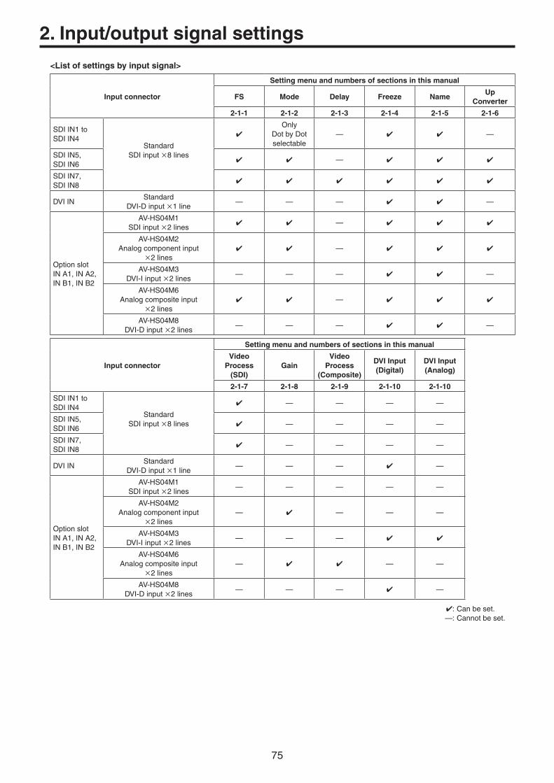
75
2. Input/output signal settings
<List of settings by input signal>
Input connector
Setting menu and numbers of sections in this manual
FS Mode Delay Freeze NameUp
Converter
2-1-1 2-1-2 2-1-3 2-1-4 2-1-5 2-1-6
SDIIN1toSDIIN4
StandardSDIinput8lines
Only
DotbyDotselectable
— —
SDIIN5,SDIIN6
—
SDIIN7,SDIIN8
DVIINStandard
DVI-Dinput1line— — — —
OptionslotINA1,INA2,INB1,INB2
AV-HS04M1SDIinput2lines
—
AV-HS04M2Analogcomponentinput
2lines —
AV-HS04M3DVI-Iinput2lines
— — — —
AV-HS04M6Analogcompositeinput
2lines —
AV-HS04M8DVI-Dinput2lines
— — — —
Input connector
Setting menu and numbers of sections in this manual
Video Process
(SDI)Gain
Video Process
(Composite)
DVI Input(Digital)
DVI Input(Analog)
2-1-7 2-1-8 2-1-9 2-1-10 2-1-10
SDIIN1toSDIIN4
StandardSDIinput8lines
— — — —
SDIIN5,SDIIN6
— — — —
SDIIN7,SDIIN8
— — — —
DVIINStandard
DVI-Dinput1line— — — —
OptionslotINA1,INA2,INB1,INB2
AV-HS04M1SDIinput2lines
— — — — —
AV-HS04M2Analogcomponentinput
2lines— — — —
AV-HS04M3DVI-Iinput2lines
— — —
AV-HS04M6Analogcompositeinput
2lines— — —
AV-HS04M8DVI-Dinput2lines
— — — —
:Canbeset. —:Cannotbeset.

76
2. Input/output signal settings
2-1-1. Setting the frame synchronizerTheframesynchronizercanbesettoOnorOffforeachinput.TheDVIinputframesynchronizerispermanentlyOn.ItcannotbesetfromOntoOfforviceversa.
1OntheInputsubmenu,use[F2]toselecttheinputtobesetusingtheSelectitem.Referto“2-1.Inputsignalsettings”.
2Use[F1]todisplaytheFSsubmenu.
3Use[F2]tosetOnorOfffortheframesynchronizerusingtheFSitem.
Iftheoutputsignalphaseissetto0H,OffcannotbeselectedastheFSitemsetting.
AVDLfunctionisactivewhiletheframesynchronizerfunctionissettoOff.TheAVDLfunctionautomaticallyadjuststheinputimagesignalphasetothehorizontalsynchronizationreferencesignalphase.Fordetails,referto“2-4.Adjustingtheoutputsignalphase”.

77
2. Input/output signal settings
2-1-2. Setting the input modeThemodecanbesetforeachinputonlywhenHDhasbeenselectedasthesystemformat.WhenSDisselectedasthesystemformat,theinputmodeisalwaysthesameasNormal.
1OntheFSsubmenu,use[F3]tosettheinputmodeusingtheModeitem.
Normal Inputsignalsinconformitywiththesystemformattakeeffect.
Dot by Dot WhenSDsignalswiththesameframerateasthesystemformathavebeeninput,theyareinputonadotbydot(1magnification)basiswithnoup-conversion.(Thissettingisonlypossiblewhenthesystemformatis1080i.)Inthismode,thereisminimaldeteriorationintheimagequalityand,assuch,themodeisusedtocombineSDformatmaterialusingthePinPfunction.
Up Convert WhenSDsignalswiththesameframerateasthesystemformathavebeeninput,theyareup-converted.
Auto Inputsignalsinconformitywiththesystemformattakeeffect.Furthermore,ifSDsignalswiththesameframerateasthesystemformatareinputwhenHDisselectedasthesystemformat,theyareup-converted.IntheAutomode,theimagesmaybedisturbedwhentheinputsignalsareswitched.
<List of input modes supported>
System ModeInput
480/ 59.94i
576/ 50i
1080/ 59.94i
1080/ 50i
1080/ 24PsF
1080/ 23.98PsF
720/ 59.94p
720/ 50p
SD 480/59.94i — w w w w w w w
576/50i — w w w w w w w
HD 1080/59.94i Normal w w w w w w w
DotbyDot w w w w w w w
UpConvert w w w w w w w
Auto
(UpConvert)w w w w w w
1080/50i Normal w w w w w w w
DotbyDot w w w w w w w
UpConvert w w w w w w w
Auto w
(UpConvert)w w w w w
1080/24PsF Normal w w w w w w w
DotbyDot w w w w w w w w
UpConvert w w w w w w w w
Auto w w w w w w w w
1080/23.98PsF Normal w w w w w w w
DotbyDot w w w w w w w w
UpConvert w w w w w w w w
Auto w w w w w w w w
720/59.94p Normal w w w w w w w
UpConvert w w w w w w w
Auto
(UpConvert)w w w w w w
720/50p Normal w w w w w w w
UpConvert w w w w w w w
Auto w
(UpConvert)w w w w w
denotesablackscreen. TheUpConvertmodeorAutomodecannotbeselectedforinputs1to4. IfDotbyDot,UpConvertorAutomodeisselected,theframesynchronizerwillbeturnedon. Theinputmodecannotbechangedwhenfreezeissettoon.
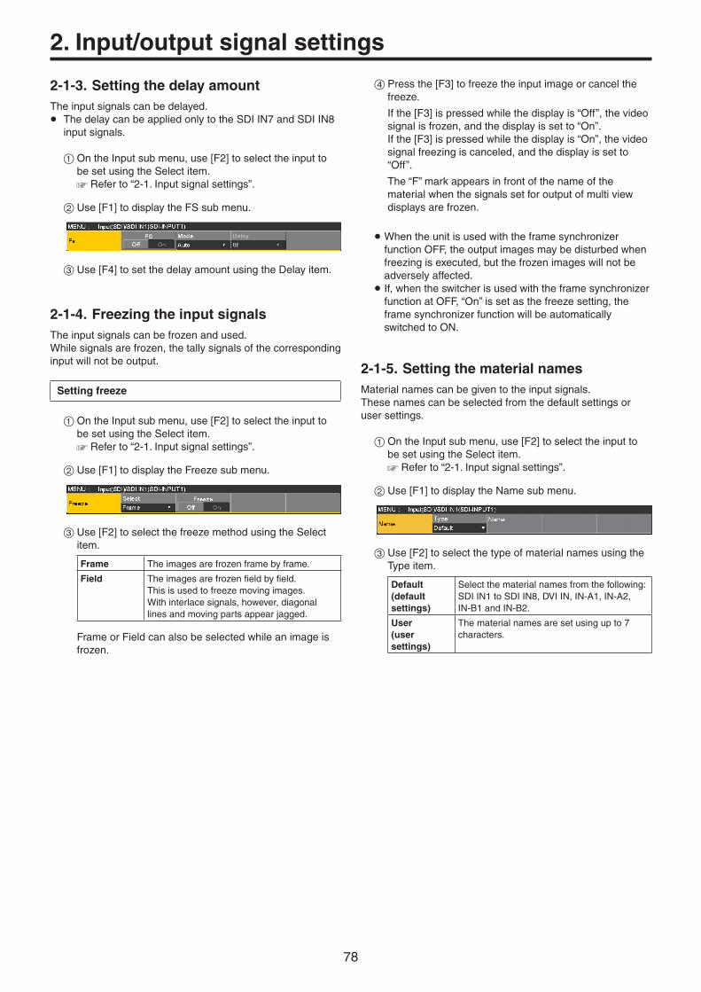
78
2. Input/output signal settings
2-1-3. Setting the delay amountTheinputsignalscanbedelayed.p ThedelaycanbeappliedonlytotheSDIIN7andSDIIN8
inputsignals.
1OntheInputsubmenu,use[F2]toselecttheinputtobesetusingtheSelectitem.Referto“2-1.Inputsignalsettings”.
2Use[F1]todisplaytheFSsubmenu.
3Use[F4]tosetthedelayamountusingtheDelayitem.
2-1-4. Freezing the input signalsTheinputsignalscanbefrozenandused.Whilesignalsarefrozen,thetallysignalsofthecorrespondinginputwillnotbeoutput.
Setting freeze
1OntheInputsubmenu,use[F2]toselecttheinputtobesetusingtheSelectitem.Referto“2-1.Inputsignalsettings”.
2Use[F1]todisplaytheFreezesubmenu.
3Use[F2]toselectthefreezemethodusingtheSelectitem.
Frame Theimagesarefrozenframebyframe.
Field Theimagesarefrozenfieldbyfield.Thisisusedtofreezemovingimages.Withinterlacesignals,however,diagonallinesandmovingpartsappearjagged.
FrameorFieldcanalsobeselectedwhileanimageisfrozen.
4Pressthe[F3]tofreezetheinputimageorcancelthefreeze.
Ifthe[F3]ispressedwhilethedisplayis“Off”,thevideosignalisfrozen,andthedisplayissetto“On”.
Ifthe[F3]ispressedwhilethedisplayis“On”,thevideosignalfreezingiscanceled,andthedisplayissetto“Off”.
The“F”markappearsinfrontofthenameofthematerialwhenthesignalssetforoutputofmultiviewdisplaysarefrozen.
WhentheunitisusedwiththeframesynchronizerfunctionOFF,theoutputimagesmaybedisturbedwhenfreezingisexecuted,butthefrozenimageswillnotbeadverselyaffected.
If,whentheswitcherisusedwiththeframesynchronizerfunctionatOFF,“On”issetasthefreezesetting,theframesynchronizerfunctionwillbeautomaticallyswitchedtoON.
2-1-5. Setting the material namesMaterialnamescanbegiventotheinputsignals.Thesenamescanbeselectedfromthedefaultsettingsorusersettings.
1OntheInputsubmenu,use[F2]toselecttheinputtobesetusingtheSelectitem.Referto“2-1.Inputsignalsettings”.
2Use[F1]todisplaytheNamesubmenu.
3Use[F2]toselectthetypeofmaterialnamesusingtheTypeitem.
Default(default settings)
Selectthematerialnamesfromthefollowing:SDIIN1toSDIIN8,DVIIN,IN-A1,IN-A2,IN-B1andIN-B2.
User(user settings)
Thematerialnamesaresetusingupto7characters.

79
2. Input/output signal settings
2-1-6. Setting the up-converterSelectthesettingsforSDIIN5toSDIIN8,aswellasfortheup-converterthatisbuiltintotheoptionboardslistedbelow:
AV-HS04M1(SDIInputBoard) AV-HS04M2(AnalogInputBoard) AV-HS04M6(AnalogCompositeInputBoard)
1OntheInputsubmenu,use[F2]toselecttheinputtobesetusingtheSelectitem.Referto“2-1.Inputsignalsettings”.
2Use[F1]todisplaytheUpConverter1submenu.
3Use[F2]toselectthescalingsystemusingtheScaleitem.
Squeeze Theimageisenlargedbothhorizontallyandverticallytofilltheentirescreen.
Edge Crop Theaspectratiooftheimageismaintained,theimagesizeisincreasedinaccordancewiththeverticalresolution,andblackbandsareaddedattheleftandright.
Letter Box Theaspectratiooftheimageismaintained,theimagesizeisincreasedinaccordancewiththehorizontalresolution,andtheimageiscroppedatthetopandbottom.
Input image Squeeze
Edge Crop Letter Box
4Use[F3]tosettheimagemovementdetectionsensitivityusingtheMoveDetectitem.
1 Towardstillimages
3 Standard
5 Towardmovingimages
5Use[F4]tosettheextentoftheedgesharpnessfortheimagesusingtheSharpitem.
1 Notsharpedges
3 Standard
5 Verysharpedges
6Use[F5]toadjusttheinputimagesize(100%to110%).
Fine-tuning of image positions
Fine-tuningofimagepositionsisperformedwhen“EdgeCrop”isselectedforthescalingmethod.
1Use[F1]todisplaytheUpConverter2submenu.
2Use[F2]toselecttheimagepositionusingtheEdgeCropPositem.
Center Theimageispositionedatthecenter,andblackimagesareaddedattheleftandright.
Right Theimageispositionedattheright,andablackimageisaddedattheleft.
Left Theimageispositionedattheleft,andablackimageisaddedattheright.
Setting the gamut limiter
1OntheUpConverter2submenu,use[F4]tosetthecolorrangeoftheinputsignalsusingtheLimiteritem.
Off Thecolorrangeisnotrestricted.
108 Theamplitudelevelofthecolors(R,GandB)isrestrictedto0%-108%.
104 Theamplitudelevelofthecolors(R,GandB)isrestrictedto0%-104%.
100 Theamplitudelevelofthecolors(R,GandB)isrestrictedto0%-100%.

80
2. Input/output signal settings
2-1-7. Setting the video process functionThevideoprocessfunctionworksforalltheSDIinputsignalimages.Thecolortonescanbechangedforeachinput.
1OntheInputsubmenu,use[F2]toselecttheinputtobesetusingtheSelectitem.Referto“2-1.Inputsignalsettings”.
2Use[F1]todisplaytheVideoProcess1submenu.
3Use[F2]toselectenable(On)ordisable(Off)forthevideoprocessfunctionusingtheVideoProcessitem.
4Use[F3]tosettheYsignalgainusingtheY-Gainitem.
5Use[F4]tosetthepedestallevelusingthePedestalitem.
6Use[F1]todisplaytheVideoProcess2submenu.
7Use[F3]tosetthesaturationgainusingtheC-Gainitem.
8Use[F4]tosetthechangeinthehueusingtheHueitem.
Copying the settings
Thevideoprocesssettingsalreadyselectedcanbesetforotherinputsignalsaswell.
OntheVideoProcess2submenu,use[F5]toselecttheinputsignalsofthecopydestination,andpress[F5].
2-1-8. Setting the analog input gain (option)
Whentheanaloginputboard(option)hasbeenconnected,thegainoftheinputsignalscanbeset.Alternatively,whentheanalogcompositeinputboard(option)hasbeenconnected,thegainoftheYsignalscanbeset.Thesettingrangeis±30steps,andthegainchangesbyapproximately±2dB.Theamountofchangeinthegainwhenitischangedbyonestepisnotfixed.
1OntheInputsubmenu,use[F2]toselecttheinputtobesetusingtheSelectitem.Referto“2-1.Inputsignalsettings”.
2Use[F1]todisplaytheVideoProcesssubmenu.
3Use[F2]tosetthegainoftheinputsignal(Ysignalgain)usingtheGainitem.

81
2. Input/output signal settings
2-1-9. Setting the analog composite input signals (option)
Whentheanalogcompositeinputboard(option)hasbeenconnected,theanalogcompositeinputsignalscanbeset.
1OntheInputsubmenu,use[F2]toselecttheinputtobesetusingtheSelectitem.Referto“2-1.Inputsignalsettings”.
2Use[F1]todisplaytheVideoProcesssubmenu.
3Use[F2]tosetthegainoftheinputsignal(Ysignalgain)usingtheGainitem.
4Use[F3]toadjustthechromalevelusingtheChromaitem.(Maximumamountofvariation:approx.±3dB)Theautocolorcontrolfunctionisactivated,andthechromaleveliskeptatthevaluethathasbeenset.
5Use[F4]toadjustthepedestallevelusingthePeditem.(Maximumamountofvariation:approx.±100mV)
6Use[F5]toadjustthehueusingtheHueitem.(Maximumamountofvariation:approx.±20°)AdjustmentofHueispossiblewhenthesystemformatis1080/59.94i,720/59.94pand480/59.94i.
Fordetailsontheothersettings,refertotheoperatinginstructionsoftheoptionboard.

82
2. Input/output signal settings
2-1-10. Setting the DVI input signalsSettheDVIinputsignalswhentheDVIinputboard(option)orfull-HDDVIinputboard(option)hasbeenconnected.Signalswiththefollowingresolutionscanbeinput.
DVI input signalsStandard(Digital)
DVI Input Board (Digital/Analog)
Full-HD DVI Input Board (Digital)
XGA(1024 768)/60 Hz
WXGA(1280 768)/60 Hz
SXGA(1280 1024)/60 Hz
WSXGA+(1680 1050)/60 Hz
—
UXGA(1600 1200)/60 Hz
—
WUXGA(1920 1200)/60 Hz
—
1080/59.94p(1920 1080)/59.94 Hz
—
1080/50p(1920 1080)/50 Hz
—
1080/59.94i(1920 1080)/59.94 Hz
— —
1080/50i(1920 1080)/50 Hz
— —
720/59.94p(1280 720)/59.94 Hz
— —
720/50p(1280 720)/50 Hz
— —
:Canbeset. —:Cannotbeset.
p Ifsignalswithanyotherresolutionsorfrequenciesareinput,thesignalscannotbeimportedcorrectly.Theimageswhichareoutputatatimelikethismaybeblackordisturbed.p TheseboardsareincompatiblewiththeHDCP(High-bandwidthDigitalContentProtection).
1OntheInputsubmenu,use[F2]toselecttheinputtobesetusingtheSelectitem.Referto“2-1.Inputsignalsettings”.
2Use[F1]todisplaytheDVIInputsubmenu.
3Use[F2]toselectthesignalsystemusingtheModeitem.SetthiswhentheDVIinputboard(AV-HS04M3)hasbeenconnected.
Digital DigitalinputsignalsoftheDVIconnectorareeffective.
Analog AnaloginputsignalsoftheDVIconnectorareeffective.
4Use[F3]toselectthescalingmethod.
Fit-V Theaspectratiooftheinputimagesismaintained,andthesizeoftheimagesisincreasedorreducedinaccordancewiththeverticalresolution.
Fit-H Theaspectratiooftheinputimagesismaintained,andthesizeoftheimagesisincreasedorreducedinaccordancewiththehorizontalresolution.
Full Thesizeoftheinputimagesisincreasedorreducedinaccordancewiththesystemresolution.(Theaspectratiooftheinputimagesisnotkeptthesame.Therateatwhichtheimagesizeisincreasedorreducedintheverticaldirectionandinthehorizontaldirectiondiffers.)
Fordetailsonthesizesthatcorrespondtotheformats,referto“DVIinputscalingsizetable”(onpage83).

83
2. Input/output signal settings
w DVI input scaling size table
DVI format ModeHD/1080i HD/720P SD/NTSC SD/PAL
1920 1080 1280 720 720 487 720 576
XGA1024 768
Fit-V 1440
1080720
960
487
720
576
720
Fit-H487
720
576
720
Full 1920
1080720
1280
487
720
576
720
SXGA1280 1024
Fit-V 1350
1080720
900
487
675
576
675
Fit-H
Full 1920
1080720
1280
487
720
576
720
WXGA1280 768
Fit-V
Fit-H
Full
:Blackimagesareinsertedhere.:Thepartsoftheimagesprotrudingintheseareasarecropped.
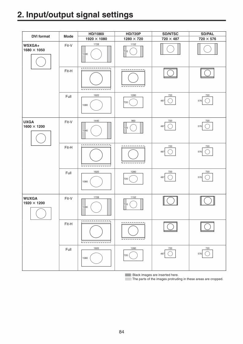
84
2. Input/output signal settings
DVI format ModeHD/1080i HD/720P SD/NTSC SD/PAL
1920 1080 1280 720 720 487 720 576
WSXGA+1680 1050
Fit-V 1728
1080720
1152
Fit-H
Full 1920
1080720
1280
487
720
576
720
UXGA1600 1200
Fit-V 1440
1080720
960
487
720
576
720
Fit-H487
720
576
720
Full 1920
1080720
1280
487
720
576
720
WUXGA1920 1200
Fit-V 1728
1080720
1152
Fit-H
Full 1920
1080720
1280
487
720
576
720
:Blackimagesareinsertedhere.:Thepartsoftheimagesprotrudingintheseareasarecropped.

85
2. Input/output signal settings
DVI format ModeHD/1080i HD/720P SD/NTSC SD/PAL
1920 1080 1280 720 720 487 720 576
1080/59.94p1080/50p1080/59.94i1080/50i
1920 1080
Fit-V 1920
1080720
1280
Fit-H 1920
1080720
1280
Full 1920
1080720
1280
720/59.94p720/50p
1280 720
Fit-V 1920
1080720
1280
Fit-H 1920
1080720
1280
Full 1920
1080720
1280
:Blackimagesareinsertedhere.:Thepartsoftheimagesprotrudingintheseareasarecropped.

86
2. Input/output signal settings
2-1-11. Displaying the DVI input signal informationTheseareusedtodisplaytheinformationconcerningtheDVI-Dinputsignalimages.Theinformationcannotbechanged.
1OntheInputsubmenu,use[F2]toselecttheinputtobesetusingtheSelectitem.Referto“2-1.Inputsignalsettings”.
2Use[F1]todisplaytheDVIStatussubmenu.
Size Thisindicatesthepixelcountoftheimages.
Dot Clock Thisindicatesthedotclockfrequencyoftheimages.
H-Frequency Thisindicatesthehorizontalfrequencyoftheimages.
V-Frequency Thisindicatestheverticalfrequencyoftheimages.
Theformatssupportedarelistedbelow.
<DVI-D formats supported>
Input video signalDot clock frequency
(MHz)
Frequency
Horizontal (kHz)
Vertical (Hz)
XGA 1024768 Digital 65.0 48.36 60.00
WXGA 1280768 Digital 79.5 47.78 59.87
SXGA 12801024 Digital 108.0 63.98 60.02
WSXGA+ 16801050 Digital 146.2 65.29 59.95
UXGA 16001200 Digital 162.0 75.00 60.00
WUXGA 19201200 Digital 154.0 74.04 59.95
1080/50p 19201080 Digital(RGB) 148.5 56.25 50.00
1080/59.94p 19201080 Digital(RGB) 148.5/1.001 67.50/1.001 60.00/1.001
1080/50i 19201080 Digital(RGB) 74.25 28.13 50.00
1080/59.94i 19201080 Digital(RGB) 74.25/1.001 33.72 60.00/1.001
720/50p 1280720 Digital(RGB) 74.25 37.50 50.00
720/59.94p 1280720 Digital(RGB) 74.25/1.001 44.96 60.00/1.001
p Iftheformatoftheinputsignalsisnotsupported,itmaynotbepossibletoimportthesignalsproperly,andablackimageordisturbedimagemayappear.

87
2. Input/output signal settings
2-1-12. Adjusting the DVI input signalsTheseareusedtoadjusttheclock/phaseandpositionoftheDVI-Dinputsignal.Selecttheclock/phaseandpositionofthesignalswhentheDVIinputboard(AV-HS04M3)hasbeenconnected.
1OntheInputsubmenu,use[F2]toselecttheinputtobesetusingtheSelectitem.Referto“2-1.Inputsignalsettings”.
2Use[F1]todisplaytheDVIPhasesubmenu.
3Use[F2]toadjusttheclockphaseoftheanaloginputsignalsusingtheClkPhsitem.Whileviewingtheimagequality,setthevalueatwhichthenoiselevelisminimized.
4Use[F3]toadjustthehorizontalpositionusingtheH-Positem.
5Use[F4]toadjusttheverticalpositionusingtheV-Positem.
2-1-13. Automatic adjustment of the black level and white level (analog input signals)
Theblacklevel(offset)andwhitelevel(gain)oftheanaloginputsignalsareadjustedautomatically.p SetthiswhentheDVIinputboard(AV-HS04M3)hasbeen
connected.
Dependingonthecomputerused,theremaybesomedeviationfromthecorrectlevelsoftheblacklevelorwhitelevel.Toproceedwithautomaticadjustmenttocorrectthisdeviation,displaytheblack-and-whitesignals(BW.bmp)onthesuppliedCD-ROMorthefull-screenblacksignalsandfull-screenwhitesignalsonthecomputerconnectedtotheDVIinputconnector,andinputthesesignalsastheDVIinputsignals.Whenusingtheblack-and-whitesignals,positionthemsothattheboundarybetweenblackandwhitecomestothecenterofthemonitorscreen.Whenusingthefull-screenblacksignalsorfull-screenwhitesignals,displaytheblackorwhiteinanareathatcoversatleast80%ofthescreenfromthescreencenter.Beforemakinganyadjustments,followtheinstructionsgiveninthe“Automaticadjustmentoftheblacklevel”section.
Automatic adjustment of the black levelInputtheblack-and-whitesignals(BW.bmp)orfull-screenblacksignals.Use[F5]toselect“Black”intheAutoitem,andpress[F5]toadjusttheblacklevelautomatically.“AutoSetting”isdisplayedonthebuilt-indisplaywhileadjustmentsarebeingmade.
Automatic adjustment of the white levelInputtheblack-and-whitesignals(BW.bmp)orfull-screenwhitesignals.Use[F5]toselect“White”intheAutoitem,andpress[F5]toadjustthewhitelevelautomatically.“AutoSetting”isdisplayedonthebuilt-indisplaywhileadjustmentsarebeingmade.
Initializing the adjusted valuesUse[F5]toselect“Init”intheAutoitem,andpress[F5]toreturntheadjustedvaluestotheirfactorysettings.“AutoSetting”isdisplayedonthebuilt-indisplaywhileadjustmentsarebeingmade.

88
2. Input/output signal settings
2-2. Output signal settingsSDIOUT1toSDIOUT5areSDIsignaloutputs.DVIOUTisDVI-Dsignaloutput.OUTA1,OUTA2,OUTB1andOUTB2canbesetonlywhenoneofthefollowingoptionboardshasbeenconnected.
AV-HS04M4(AnalogOutputBoard) AV-HS04M5(DVI/AnalogOutputBoard) AV-HS04M7(SDIOutputBoard)
Beforeproceedingtosettheoutputsignals,firstselecttheoutputsignalstobesetusingtheOutputsubmenu.
1Presstheibuttontolightitsindicator,anddisplaytheOutputmenu.
2Use[F1]todisplaytheOutputsubmenu.
3Use[F2]toselecttheoutputsignalsusingtheSelectitem.
Themenudisplayisswitcheddependingontheselectedoutputsignals.Themenutitleissetto“MENU:Output(signaltype)/outputconnector”.
Signal type SDI,Analog,DVI-D,DVI-I
<Example of menu (SDI)>
<List of settings by output signal>
Output connector
Setting menu and numbers of sections in this manual
Assign SDI OutputDVI Output
(Digital)DVI Output
(Analog)Down
Converter
2-2-1 2-2-2 2-2-3 2-2-3 2-2-4
SDIOUT1toSDIOUT5
StandardSDIoutput5lines
— — —
DVIOUTStandard
DVI-Doutput1line — — —
OptionslotOUTA1,OUTA2,
AV-HS04M4Analogcomponentoutput2lines
— — — —
AV-HS04M5DVI-Ioutput1line
Analogcomponentoutput1line — — —
AV-HS04M7SDIoutput2lines
— —
OptionslotOUTB1,OUTB2
AV-HS04M4Analogcomponentoutput2lines
— — — —
AV-HS04M5DVI-Ioutput1line
Analogcomponentoutput1line — — —
AV-HS04M7SDIoutput2lines
— —
:Canbeset. —:Cannotbeset.

89
2. Input/output signal settings
2-2-1. Assigning the output signalsTheoutputsignalscanbeassignedtotheSDIOUT1toSDIOUT5connectorsandDVIOUTconnector.
1OntheOutputsubmenu,use[F2]toselecttheoutputtobesetusingtheSelectitem.Referto“2-2.Outputsignalsettings”.
2Use[F1]todisplaytheAssignsubmenu.
3Use[F2]tosetthetypeofoutputsignalusingtheSourceitem.
PGM Animageprovidedwiththewipe,mix,key,downstreamkeyorothereffectisoutputattheswitcher’smainlineoutput.
PVW Thisisthepreviewoutputthatenablesthenextoperationtobecheckedbeforeitisexecuted.
AUX1 to 4 Thesignalsselectedbythe4linesofAUXbuses(AUX1toAUX4)areoutput.
CLN Thecleansignal(theimageresultingwhenthekey,downstreamkeyorothereffecthasbeenremovedfromthePGMsignal)isoutput.Referto“AssigningtheCLNsignal”.
MV Themultiviewdisplaysignalsareoutput.Multipleinputsignalsandoutputsignalsarereducedinsizeandoutputtoonescreen.
KeyOut Thekeysignalisoutput.
MEM-PVW Inthememorypreviewmode,theshotmemoryandeventmemoryeffectsareoutputtopreview.
4Use[F3]tosettheoutputmodeusingtheModeitem.
Normal Thesamesignalsasthesystemformatsignalsareoutput.
Down Convert(down-converter)
ThiscanbeselectedwhentheSDIoutputboard(option:AV-HS04M7)hasbeenconnected.Whenthesystemformatis1080/59.94ior720/59.94p,thesignalsareoutputinthe480/59.94iformat.Whenthesystemformatis1080/50ior720/50p,thesignalsareoutputinthe576/50iformat.WhenthesystemformatisSD(480/59.94ior576/50i),thissettingcannotbeselected.
Assigning the CLN signal
SetKEYCLNorDSKCLNastheCLNoutput.
1Pressthesbuttontolightitsindicator,anddisplaytheConfigmenu.
2Use[F1]todisplaytheAssignsubmenu.
3Use[F3]toselectthetypeofoutputsignalusingtheCLNitem.
Key ThePGMsignalsminusthekeyeffectsareoutput.TheKey,PinP1,PinP2andDSKeffectsarenotadded.
DSK ThePGMsignalminusthedownstreamkeyeffectsareoutput.
2-2-2. Setting the SDI output color rangeThecolorrangecanbesetfortheSDIoutputsignalimages.p ThesamesettingappliestoalltheSDIoutputsignals.
1OntheOutputsubmenu,use[F5]tosetthecolorrangeusingtheSDILimititem.Referto“2-2.Outputsignalsettings”.
Off Thecolorrangeisnotrestricted.
108 Theamplitudelevelofthecolors(R,GandB)isrestrictedto0%-108%.
104 Theamplitudelevelofthecolors(R,GandB)isrestrictedto0%-104%.
100 Theamplitudelevelofthecolors(R,GandB)isrestrictedto0%-100%.

90
2. Input/output signal settings
2-2-3. Setting the DVI output signalsSettheDVIoutputsignalsofthestandardoutput(DVIOUT)andtheDVIoutputsignalsiftheDVI/analogoutputboard(option)hasbeenconnected.
1OntheOutputsubmenu,use[F2]toselecttheoutputtobesetusingtheSelectitem.Referto“2-2.Outputsignalsettings”.
2Use[F1]todisplaytheDVIOutputsubmenu.
3Use[F2]toselectthesignalsystemusingtheModeitem.SetthiswhentheDVI/analogoutputboard(AV-HS04M5)hasbeenconnected.
Digital DVIdigitalsignalsareoutputfromtheDVIconnector.
Analog DVIanalogsignals(RGB)areoutputfromtheDVIconnector.When“Analog”hasbeenselected,thedisplaypositionoftheimagemaybeoffdependingonthemonitorwhichisconnected.Ifitisoff,adjustthepositionatthemonitor.Fordetailsontheadjustmentmethod,refertotheoperatinginstructionsofthemonitor.
4Use[F3]toselecttheresolutionoftheimagestobeoutputusingtheSizeitem.
Auto TheequipmentinformationoftheoutputdestinationiscapturedbytheDVIsignals,andtheimagesareoutputattheoptimumresolution.Theverticalfrequencyis60Hz,andthemaximumresolutionisSXGAforanalogoutputsignalsandWUXGAfordigitaloutputsignals.Iftheequipmentinformationcannotbecapturedoriftheresolutionandfrequencywhichcanbeoutputbytheunitarenotcontainedintheequipmentinformation,theimageswillbeoutputattheXGAsetting.
Othersignalsarelistedinthetablebelow.
<Table of DVI output signal settings>DVI output signal Standard output (DVI OUT) DVI/Analog Output Board
Size Output (Digital) (Digital) (Analog)
XGA (1024768)/60Hz
WXGA (1280768)/60Hz
SXGA (12801024)/60Hz
WSXGA+ (16801050)/60Hz —
UXGA (16001200)/60Hz —
WUXGA (19201200)/60Hz —
1080/59.94p (19201080)/59.94Hz —
1080/50p (19201080)/50Hz —
1080/59.94i (19201080)/59.94Hz — —
1080/50i (19201080)/50Hz — —
720/59.94p (1280720)/59.94Hz — —
720/50p (1280720)/50Hz — —
:Canbeset. —:Cannotbeset.
TheDVIsignalscannotbeoutputifthesystemformatis1080/23.98PsFor1080/24PsF.

91
2. Input/output signal settings
5Use[F4]toselectthescalingmethodusingtheScaleitem.
Fit-V Theaspectratiooftheoutputimagesismaintained,andthesizeoftheimagesisincreasedorreducedinaccordancewiththeverticalresolution.(Blackbandsareinsertedintotheareaswheretherearenoimages.Theprotrudingpartsoftheimagesarecropped.)
Fit-H Theaspectratiooftheoutputimagesismaintained,andthesizeoftheimagesisincreasedorreducedinaccordancewiththehorizontalresolution.(Blackbandsareinsertedintotheareaswheretherearenoimages.Theprotrudingpartsoftheimagesarecropped.)
Full Thesizeoftheoutputimagesisincreasedorreducedinaccordancewiththesystemresolution.
Fullx80% Thesizeoftheoutputimageisincreasedorreducedinaccordancewiththe80%sizeofthesystemresolution.
Fullx90% Thesizeoftheoutputimageisincreasedorreducedinaccordancewiththe90%sizeofthesystemresolution.
TheaspectratioisnotmaintainedattheFull,Fullx80%orFullx90%setting.Therateatwhichtheimagesizeisincreasedorreducedintheverticaldirectionandinthehorizontaldirectiondiffers.
w Setting the video movement detection sensitivity
1Use[F1]todisplaytheAssignsubmenu.
2Use[F3]tosettheimagemovementdetectionsensitivityusingtheMoveDetectitem.
1 Towardstillimages
3 Standard
5 Towardmovingimages
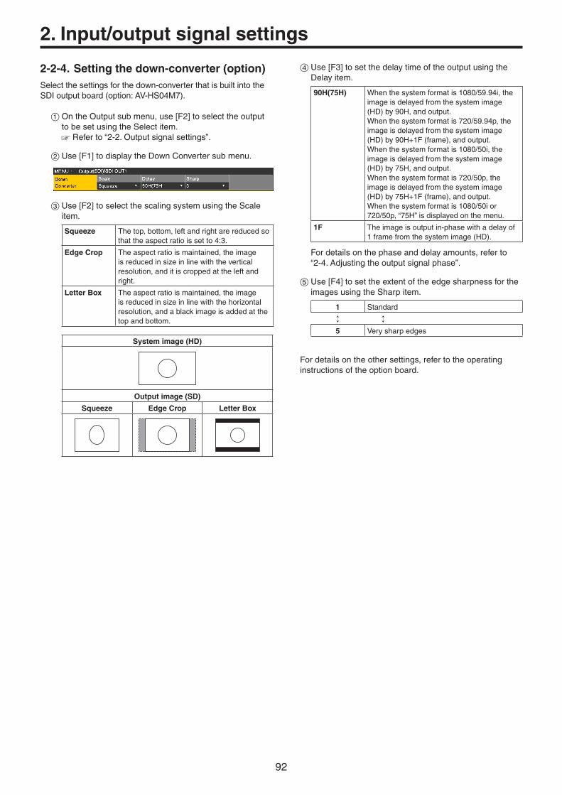
92
2. Input/output signal settings
2-2-4. Setting the down-converter (option)Selectthesettingsforthedown-converterthatisbuiltintotheSDIoutputboard(option:AV-HS04M7).
1OntheOutputsubmenu,use[F2]toselecttheoutputtobesetusingtheSelectitem.Referto“2-2.Outputsignalsettings”.
2Use[F1]todisplaytheDownConvertersubmenu.
3Use[F2]toselectthescalingsystemusingtheScaleitem.
Squeeze Thetop,bottom,leftandrightarereducedsothattheaspectratioissetto4:3.
Edge Crop Theaspectratioismaintained,theimageisreducedinsizeinlinewiththeverticalresolution,anditiscroppedattheleftandright.
Letter Box Theaspectratioismaintained,theimageisreducedinsizeinlinewiththehorizontalresolution,andablackimageisaddedatthetopandbottom.
System image (HD)
Output image (SD)
Squeeze Edge Crop Letter Box
4Use[F3]tosetthedelaytimeoftheoutputusingtheDelayitem.
90H(75H) Whenthesystemformatis1080/59.94i,theimageisdelayedfromthesystemimage(HD)by90H,andoutput.Whenthesystemformatis720/59.94p,theimageisdelayedfromthesystemimage(HD)by90H+1F(frame),andoutput.Whenthesystemformatis1080/50i,theimageisdelayedfromthesystemimage(HD)by75H,andoutput.Whenthesystemformatis720/50p,theimageisdelayedfromthesystemimage(HD)by75H+1F(frame),andoutput.Whenthesystemformatis1080/50ior720/50p,“75H”isdisplayedonthemenu.
1F Theimageisoutputin-phasewithadelayof1framefromthesystemimage(HD).
Fordetailsonthephaseanddelayamounts,referto“2-4.Adjustingtheoutputsignalphase”.
5Use[F4]tosettheextentoftheedgesharpnessfortheimagesusingtheSharpitem.
1 Standard
5 Verysharpedges
Fordetailsontheothersettings,refertotheoperatinginstructionsoftheoptionboard.

93
2. Input/output signal settings
2-3. Setting the sync signalsThesyncsignalstobeusedbythesystemcanbeselected.
External sync: Forsynchronizationwithanexternalsyncsignal
(gen-lock). Thereferenceinputsignalisloopedthroughandoutput.
BB Blackburstsignal(verticalphaseof0H)
BB Advanced
BlackburstsignalVerticalphaseof90Hwhenthe59.94ior59.94pformatisselected;verticalphaseof75Hwhenthe50ior50pformatisselected
Tri-level sync Tri-levelsyncsignal(verticalphaseof0H)Thiscanbeselectedwhenthesystem
formatis1080/24PsF.
Internal Forsynchronizationwithaninternalreferencesignal(INT).TheREFOUTsignal(blackburstsignal)isoutputfromthetworeferenceconnectors.Thiscannotbeselectedwhenthesystem
formatis1080/24PsF.
When1080/24PsFisselectedastheformat,INT(internalsynchronization)cannotbeselectedintheSyncitemoftheReferencesubmenu. Thisunitsupportssynchronizationsignalsforfieldfrequenciesthataresameasthoseofthesystemformat.Whentheunitissettothe1080/23.98PsFformat,however,theunitalsosupportsblackburstsignalswith10F-1D(compliantwiththeSMPTE318Mstandard).
1Pressthesbuttontolightitsindicator,anddisplaytheSystemmenu.
2Use[F1]todisplaytheReferencesubmenu.
3Use[F2],selectthesyncsignalusingtheSyncitem,andpressthe[F2]toentertheselection.
4Use[F3]toselectthesetupleveloftheblackburstsignalintheinternalsynchronizationmodeusingtheBBSetupitem.Thissettingtakeseffectwhenthevideosystemis59.94ior59.94p.Thesetuplevelisfixedat0IREwhenthesystemis50ior50p.
5ThegenlockstatusisdisplayedintheGenLockitem.
Locked Synchronizedwiththeexternalsyncsignalorinternalreferencesignal.
UnLock Notsynchronizedwiththeexternalsyncsignalorinternalreferencesignal.
2-4. Adjusting the output signal phase
Thephaseoftheoutputvideosignalscanbeadjusted.
1Pressthesbuttontolightitsindicator,anddisplaytheSystemmenu.
2Use[F1]todisplaytheOutputPhasesubmenu.
3Use[F2],andselect“0H”or“1H”usingtheSystemitem.
0H TheoutputvideosignalsareoutputtothesystemReferencesignalwithusingin-phase.TheframesynchronizerfunctionisONforallinputsignals.
1H TheoutputvideosignalsareoutputtothesystemReferencesignalwith1Hdelay.WhentheframesynchronizerfunctionisON,theoutputvideosignalsareoutputwith1frame+1Hdelay.
4Use[F3]toadjustHphaseusingtheH-Phaseitem.H-Phasecanbeadjustedwithinarangeof–0.5Hto+0.5H.
Thesettingdisplayedonthemenudiffersdependingonthesystemformat.
5Use[F4]toadjustVphaseusingtheV-Phaseitem.V-Phasecanbeadjustedwithinarangeof–100Hto+100H.

94
2. Input/output signal settings
<Phase adjustment setup>
Reference (Phase Reference)
H Phase (–0.5H to +0.5H) + V Phase (±100 lines)
InternalFixed DL
Approx. 0.2H
• 0H Output (1F delay for Reference and in-phase output)
FS Range
MAX less than approximately 1 frame
Longest Output(+1.5H)
Approx. 0.3H
+0.5H
Output Phase Variable Range
Output Phase Variable Range
H Phase (–0.5H to +0.5H) + V Phase (±100 lines)
Approx. +0.3H to +1.3H InternalFixed DL
AVDL Range
Reference(System standard)
• 1H Output (+1H)
ShortestOutput (+0.5H)
Output Phase Variable Range
H Phase (–0.5H to +0.5H) + V Phase (±100 lines)
Approx. 0.3H
+0.5H
InternalFixed DL
Approx. –0.7H to +0.3H
AVDL Range
H Phase (–0.5H to +0.5H) + V Phase (±100 lines)
Output Phase Variable Range
InternalFixed DL
Approx. –0.2H to +0.8HApprox.
0.2H
AVDL Range
Approx. 0.2H
AVDL Range:Rangeforautomaticphaseadjustment.
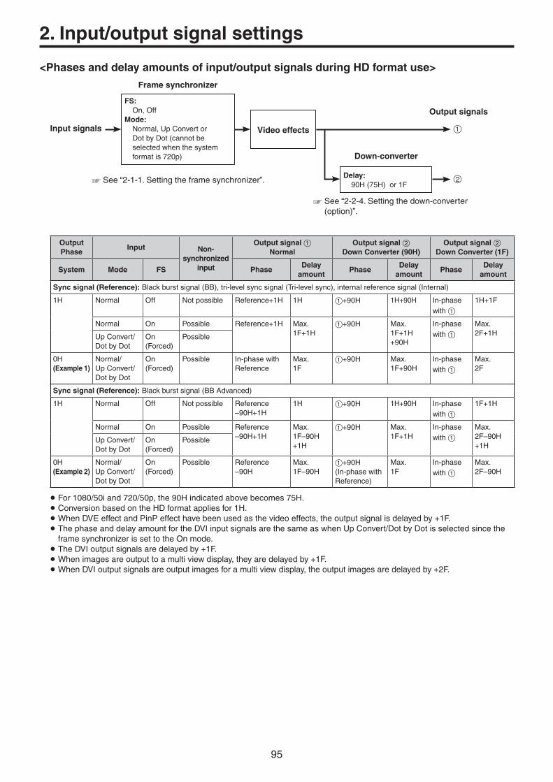
95
2. Input/output signal settings
<Phases and delay amounts of input/output signals during HD format use>
Input signals
FS: On,OffMode: Normal,UpConvertor
DotbyDot(cannotbeselectedwhenthesystemformatis720p)
Video effects
Output signals
1
Delay: 90H(75H)or1F
2See“2-1-1.Settingtheframesynchronizer”.
See“2-2-4.Settingthedown-converter(option)”.
Frame synchronizer
Down-converter
Output Phase
Input Non-synchronized
input
Output signal 1 Normal
Output signal 2 Down Converter (90H)
Output signal 2 Down Converter (1F)
System Mode FS PhaseDelay
amountPhase
Delay amount
PhaseDelay
amount
Sync signal (Reference):Blackburstsignal(BB),tri-levelsyncsignal(Tri-levelsync),internalreferencesignal(Internal)
1H Normal Off Notpossible Reference+1H 1H 1+90H 1H+90H In-phasewith1
1H+1F
Normal On Possible Reference+1H Max.1F+1H
1+90H Max.1F+1H+90H
In-phasewith1
Max.2F+1HUpConvert/
DotbyDotOn(Forced)
Possible
0H(Example 1)
Normal/UpConvert/DotbyDot
On(Forced)
Possible In-phasewithReference
Max.1F
1+90H Max.1F+90H
In-phasewith1
Max.2F
Sync signal (Reference):Blackburstsignal(BBAdvanced)
1H Normal Off Notpossible Reference–90H+1H
1H 1+90H 1H+90H In-phasewith1
1F+1H
Normal On Possible Reference–90H+1H
Max.1F–90H+1H
1+90H Max.1F+1H
In-phasewith1
Max.2F–90H+1H
UpConvert/DotbyDot
On(Forced)
Possible
0H(Example 2)
Normal/UpConvert/DotbyDot
On(Forced)
Possible Reference–90H
Max.1F–90H
1+90H(In-phasewithReference)
Max.1F
In-phasewith1
Max.2F–90H
For1080/50iand720/50p,the90Hindicatedabovebecomes75H. ConversionbasedontheHDformatappliesfor1H.WhenDVEeffectandPinPeffecthavebeenusedasthevideoeffects,theoutputsignalisdelayedby+1F. ThephaseanddelayamountfortheDVIinputsignalsarethesameaswhenUpConvert/DotbyDotisselectedsincetheframesynchronizerissettotheOnmode. TheDVIoutputsignalsaredelayedby+1F.Whenimagesareoutputtoamultiviewdisplay,theyaredelayedby+1F.WhenDVIoutputsignalsareoutputimagesforamultiviewdisplay,theoutputimagesaredelayedby+2F.

96
2. Input/output signal settings
<Phase relationship between input signals and output signals>(for 1080/59.94i format)
(Example 1)
F1 F2
F1 F2
F1 F2
F1 F2
Input signals (non-synchronized)
1F (frame)
Sync signal (Reference)
Output signal 1
Output signal 2 (90H)
Output signal 2 (1F)
Max. 1F
Max. 2F
Max. 1F+90H
(Example 2)
F1 F2
F1 F2
F1 F2
F1 F2
Input signals (non-synchronized)
1F (frame)
Sync signal (Reference)
Output signal 1
Output signal 2 (90H)
Output signal 2 (1F)
Max. 1F–90H
Max. 2F–90H
Max. 1F
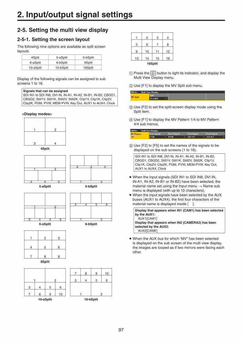
97
2. Input/output signal settings
2-5. Setting the multi view display
2-5-1. Setting the screen layoutThefollowingnineoptionsareavailableassplitscreenlayouts.
4Split 5-aSplit 5-bSplit
6-aSplit 6-bSplit 9Split
10-aSplit 10-bSplit 16Split
Displayofthefollowingsignalscanbeassignedtosubscreens1to16.
Signals that can be assignedSDIIN1toSDIIN8,DVIIN,IN-A1,IN-A2,IN-B1,IN-B2,CBGD1,CBGD2,Still1V,Still1K,Still2V,Still2K,Clip1V,Clip1K,Clip2V,Clip2K,PGM,PVW,MEM-PVW,KeyOut,AUX1toAUX4,Clock
<Display modes>
43
21
4Split
21
53 4
5-bSplit
21
53 4
5-aSplit
21
63 4 5
6-bSplit
21
653 4
6-aSplit
7 8 9
4 5 6
1 2 3
9Split
1
7 8 9 10
3 4 5 6
2
10-bSplit
1
3 4 5 6
7 8 9 10
2
10-aSplit
1 2 3 4
5 6 7 8
9 10 11 12
13 14 15 16
16Split
1Pressthexbuttontolightitsindicator,anddisplaytheMultiViewDisplaymenu.
2Use[F1]todisplaytheMVSplitsubmenu.
3Use[F2]tosetthesplit-screendisplaymodeusingtheSplititem.
4Use[F1]todisplaytheMVPattern1/4toMVPattern4/4submenus.
5Use[F2]to[F5]tosetthenamesofthesignalstobedisplayedonthesubscreens(1to16).
SDIIN1toSDIIN8,DVIIN,IN-A1,IN-A2,IN-B1,IN-B2,CBGD1,CBGD2,Still1V,Still1K,Still2V,Still2K,Clip1V,Clip1K,Clip2V,Clip2K,PGM,PVW,MEM-PVW,KeyOut,AUX1toAUX4,Clock
Whentheinputsignals(SDIIN1toSDIIN8,DVIIN,IN-A1,IN-A2,IN-B1orIN-B2)havebeenselected,thematerialnamesetusingtheInputmenuNamesubmenuisdisplayed(withupto10characters).
WhentheinputsignalshavebeenselectedbytheAUXbuses(AUX1toAUX4),thefirstfourcharactersofthematerialnameisdisplayedinside[].
Display that appears when IN1 (CAM1) has been selected by the AUX1: AUX1[CAM1]Display that appears when IN2 (CAMERA2) has been selected by the AUX2: AUX2[CAME]
WhentheAUXbusforwhich“MV”hasbeenselectedisdisplayedonthesubscreenofthemultiviewdisplay,theimagesareloopedasiftwomirrorswerefacingeachother.

98
2. Input/output signal settings
2-5-2. Setting the split frame and characters
Settheframe,characterbrightnessandbackgroundofthesplitscreenstobedisplayedonthemultiviewdisplay.
1Pressthexbuttontolightitsindicator,anddisplaytheMultiViewDisplaymenu.
2Use[F1]todisplaytheMVFramesubmenu.
3Use[F2]tosetthesplitframebrightnessandsplitframedisplayusingtheFrameitem.
LUM0%, LUM25%, LUM50%, LUM75%, LUM100%
Selectoneofthesesettingsforthebrightnessofthesplitframe(grayscale).
Off Thesplitframeisnotdisplayed.
4Use[F3]tosetthecharacterbrightnessandcharacterdisplayusingtheCharacteritem.
LUM0%, LUM25%, LUM50%, LUM75%, LUM100%
Selectoneofthesecharacter(grayscale)brightnesssettings.
Off Thecharactersarenotdisplayed.Neitheristhecharacterbackgroundshown.
5Use[F4]tosetwhetherthecharacterbackground(half-tone)istobedisplayedusingtheLabelitem.
On Thecharacterbackgroundisdisplayed.
Off Thecharacterbackgroundisnotdisplayed.
2-5-3. Setting the tally displaysSetthetallydisplaystobesuperimposedontothesplitframeofthemultiviewdisplay.Theredtallyindicatesmaterialconsistingofprogramoutputs.Thegreentallyindicatesmaterialselectedbythepresetbus.
OntheMVFramesubmenu,use[F5]tosetthetallydisplaysusingtheTallyitem.
Red+Green Boththeredtallyandgreentallyaredisplayed.
Red Onlytheredtallyisdisplayed.
Off Notallydisplaysareshown.
TheredtallyisnotdisplayedduringFTBoperationwhiletheprogramimageshavebeencompletelyfadedouttoablackscreen.Atthistime,thegreentallyisdisplayedforimagesconsistingofprogramimages.However,theredtallyisdisplayedwhenasettingotherthan“White”or“Black”hasbeenselectedfortheimageusedforfadingout.Referto“1-7.FTB(FadetoBlack)”.
Theredtallyandgreentallysignalsareoutputfromthetallyoutputconnectorontherearpanel.Referto“4-1.SettingtheGPII/O”.

99
2. Input/output signal settings
2-5-4. Changing the material namesThematerialnamesoftheinputsignals(SDIIN1toSDIIN8,DVIIN,IN-A1,IN-A2,IN-B1orIN-B2)tobesetonthemultiviewdisplaycanbechanged.Thesenamescanbeselectedfromthedefaultsettingsorusersettings.Whenthepresetsettingsandusersettingsareestablished,thematerialname(CAM1,etc.)isdisplayed.
1OntheInputsubmenu,use[F2]toselecttheinputtobesetusingtheSelectitem.Referto“2-1.Inputsignalsettings”.
2Use[F1]todisplaytheNamesubmenu.
3Use[F2]toselectthetypeofmaterialnamesusingtheTypeitem.
Default(default settings)
Selectthematerialnamesfromthefollowing:SDIIN1toSDIIN8,DVIIN,IN-A1,IN-A2,IN-B1andIN-B2.
User(user settings)
Thematerialnamesaresetusingupto7characters.
Preset type setting procedure
1OntheNamesubmenu,use[F2]toselect“Preset”usingtheTypeitem.
2Use[F3]toselectthematerialnameusingtheNameitem.
User type setting procedure
1OntheNamesubmenu,use[F2]toselect“User”usingtheTypeitem.
2Press[F3]todisplaythekeyboardscreen.
3Using[F1]to[F3],inputthename,andpress[F4].Toclearthenamewhichhasbeeninputandclosethekeyboardscreen,press[F5].Referto“2-2-2.Keyboardscreenoperations”
(<Basics>OperatingInstructions).

100
2. Input/output signal settings
2-5-5. Setting the level metersLevelmetersfortheembeddedaudiosignalstransferredbytheSDIinputcanbedisplayedonthesplitscreens.
Left display: Channel1ofgroup1Right display: Channel2ofgroup1
1Pressthexbuttontolightitsindicator,anddisplaytheMultiViewDisplaymenu.
2Use[F1]todisplaytheDisplaysubmenu.
3Use[F2]tosetthelevelmeterdisplayusingtheLevelMeteritem.
On Thelevelmetersaredisplayed.
Off Thelevelmetersarenotdisplayed.
2-5-6. Setting the input signal marksThestatusoftheinputsignalscanbedisplayedinfrontofthematerialnamesdisplayedonthesplitscreens.
“F” mark: Thisappearswhentheinputsignalsarefrozen.“ ! ” mark: Thisappearswhennosignalsareinputorwhensignals
withdifferentformatsareinput.
Whenthe“F”markisdisplayed,the“!”markisnotdisplayed.
1OntheDisplaysubmenu,use[F3]tosettheinputsignalstatusdisplayusingtheInputStatusitem.
On Theinputsignalstatusisdisplayed.
Off Theinputsignalstatusisnotdisplayed.
2-5-7. Setting the markersSafetymarkerscanbedisplayedforthemultiviewmaterials.ThemarkerscanbedisplayedwhenPGMorPVWmaterialsaretobedisplayedinhalftheiroriginalsize.
4Split Subscreens1to4
5/6/10Split 1or2subscreens
1OntheDisplaysubmenu,use[F4]tosetthemarkerdisplayusingtheMarkeritem.
4:3 Themarkersaredisplayedusingthe4:3aspectratio.
16:9 Themarkersaredisplayedusingthe16:9aspectratio.
Off Themarkersarenotdisplayed.
2Use[F5]tosetthesizeofthemarkersusingtheMarkerSizeitem.
2-5-8. High-resolution multi view modeTheimageoutputonamultiviewdisplaycanbeoutputinhighresolutiontoDVI-Doutput.p Thesesettingscanbeestablishedwhenthesystemmode
issettoSD.
1Pressthesbuttontolightitsindicator,anddisplaytheSystemmenu.
2Use[F1]todisplaytheFormatsubmenu.
3Use[F3]toset“On”or“Off”usingtheHiResolutionitem,andpressthe[F3].
Turningthissetting“On”switchestheSourceitemtothedefaultvalueifthefollowingoutputsignalsintheSourceitemoftheAssignsubmenuundertheOutputmenuaresetto“MV”.
SDIOUT1toSDIOUT5,OUT-A1,OUT-A2,OUT-B1,OUT-B2
Turningthissetting“On”,whilethemultiviewdisplaysignalisoutputtotheAUXbusorDISPbus,switchestheoutputsignaltotheblacksignal(internallygeneratedsignal).

101
2. Input/output signal settings
2-6. Setting the ancillary data and embedded audio data
AfunctionforallowingtheVancillarydataandembeddedaudiodataoftheSDIinputsignalstopassthroughcanbeset.
When an HD format is used: Theancillarydatastartingwithline9isallowedtopass
through.When an SD format is used: Theancillarydatastartingwithline12isallowedto
passthrough.
p When1080/59.94i,720/59.94p,1080/50ior720/50phasbeenselectedastheunit’ssystemformatsetting,itisnotpossibletoallowtheancillarydataandembeddedaudiodatatopassthroughevenifSDformatsignals(480/59.94ior576/50i)havebeeninputintheDotbyDotmodeorUpConvertmode.Referto“2-1-2.Settingtheinputmode”.
1Pressthesbuttontolightitsindicator,anddisplaytheSystemmenu.
2Use[F1]todisplaytheAncillarysubmenu.
Setting for the program output signals
3Use[F3]toselect“On”or“Off”usingthePGMitem.
On TheancillarydataandembeddedaudiodataoftheSDIinputmaterialsselectedbythePGMbusareallowedtopassthrough.
Off Theancillarydataandembeddedaudiodataarenotallowedtopassthrough.
Setting for the preview output signals
4Use[F4]toselect“On”or“Off”usingthePVWitem.
On TheancillarydataandembeddedaudiodataoftheSDIinputmaterialsselectedbythePSTbusareallowedtopassthrough.
Off Theancillarydataandembeddedaudiodataarenotallowedtopassthrough.
Setting for the output signals of the multi view display
5Use[F5]toselect“PGM”,“PVW”or“Off”usingtheMVitem.
PGM TheancillarydataandembeddedaudiodataoftheSDIinputmaterialsselectedbythePGMbusareallowedtopassthrough.
PVW TheancillarydataandembeddedaudiodataoftheSDIinputmaterialsselectedbythePSTbusareallowedtopassthrough.
Off Theancillarydataandembeddedaudiodataarenotallowedtopassthrough.
Setting for the output signals of the AUX buses (AUX1 to AUX4)
6Use[F2]toselect“On”or“Off”usingtheAUXitem.
On TheancillarydataandembeddedaudiodataoftheSDIinputmaterialsselectedbytheAUXbus(AUX1toAUX4)areallowedtopassthrough.
Off Theancillarydataandembeddedaudiodataarenotallowedtopassthrough.
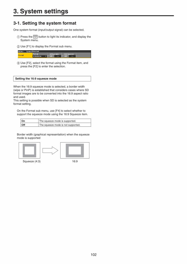
102
3. System settings
3-1. Setting the system formatOnesystemformat(input/outputsignal)canbeselected.
1Pressthesbuttontolightitsindicator,anddisplaytheSystemmenu.
2Use[F1]todisplaytheFormatsubmenu.
3Use[F2],selecttheformatusingtheFormatitem,andpressthe[F2]toentertheselection.
Setting the 16:9 squeeze mode
Whenthe16:9squeezemodeisselected,aborderwidth(wipeorPinP)isestablishedthatconsiderscaseswhereSDformatimagesaretobeconvertedintothe16:9aspectratioandused.ThissettingispossiblewhenSDisselectedasthesystemformatsetting.
OntheFormatsubmenu,use[F4]toselectwhethertosupportthesqueezemodeusingthe16:9Squeezeitem.
On Thesqueezemodeissupported.
Off Thesqueezemodeisnotsupported.
Borderwidth(graphicalrepresentation)whenthesqueezemodeissupported
Squeeze(4:3) 16:9
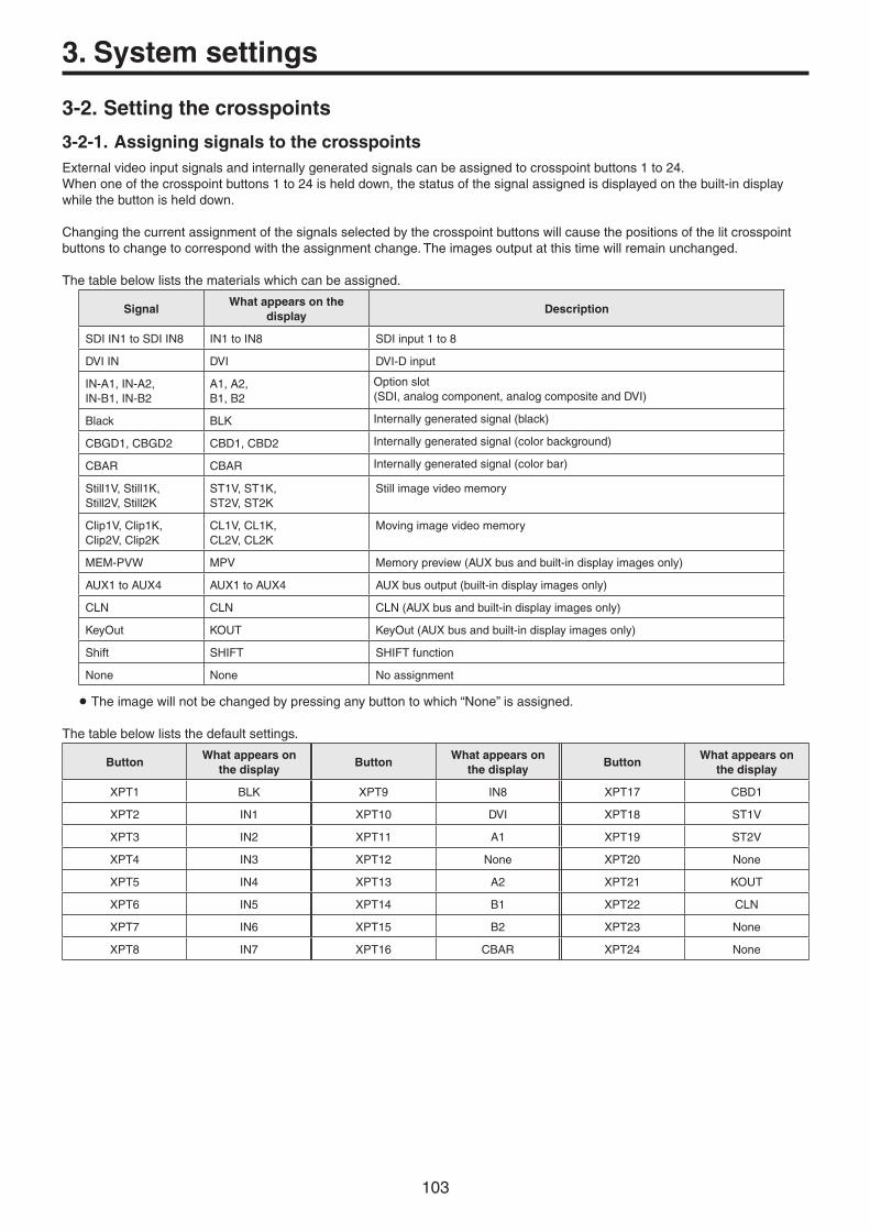
103
3. System settings
3-2. Setting the crosspoints
3-2-1. Assigning signals to the crosspointsExternalvideoinputsignalsandinternallygeneratedsignalscanbeassignedtocrosspointbuttons1to24.Whenoneofthecrosspointbuttons1to24ishelddown,thestatusofthesignalassignedisdisplayedonthebuilt-indisplaywhilethebuttonishelddown.
Changingthecurrentassignmentofthesignalsselectedbythecrosspointbuttonswillcausethepositionsofthelitcrosspointbuttonstochangetocorrespondwiththeassignmentchange.Theimagesoutputatthistimewillremainunchanged.
Thetablebelowliststhematerialswhichcanbeassigned.
SignalWhat appears on the
displayDescription
SDIIN1toSDIIN8 IN1toIN8 SDIinput1to8
DVIIN DVI DVI-Dinput
IN-A1,IN-A2,IN-B1,IN-B2
A1,A2,B1,B2
Optionslot(SDI,analogcomponent,analogcompositeandDVI)
Black BLK Internallygeneratedsignal(black)
CBGD1,CBGD2 CBD1,CBD2 Internallygeneratedsignal(colorbackground)
CBAR CBAR Internallygeneratedsignal(colorbar)
Still1V,Still1K,Still2V,Still2K
ST1V,ST1K,ST2V,ST2K
Stillimagevideomemory
Clip1V,Clip1K,Clip2V,Clip2K
CL1V,CL1K,CL2V,CL2K
Movingimagevideomemory
MEM-PVW MPV Memorypreview(AUXbusandbuilt-indisplayimagesonly)
AUX1toAUX4 AUX1toAUX4 AUXbusoutput(built-indisplayimagesonly)
CLN CLN CLN(AUXbusandbuilt-indisplayimagesonly)
KeyOut KOUT KeyOut(AUXbusandbuilt-indisplayimagesonly)
Shift SHIFT SHIFTfunction
None None Noassignment
Theimagewillnotbechangedbypressinganybuttontowhich“None”isassigned.
Thetablebelowliststhedefaultsettings.
ButtonWhat appears on
the displayButton
What appears on the display
ButtonWhat appears on
the display
XPT1 BLK XPT9 IN8 XPT17 CBD1
XPT2 IN1 XPT10 DVI XPT18 ST1V
XPT3 IN2 XPT11 A1 XPT19 ST2V
XPT4 IN3 XPT12 None XPT20 None
XPT5 IN4 XPT13 A2 XPT21 KOUT
XPT6 IN5 XPT14 B1 XPT22 CLN
XPT7 IN6 XPT15 B2 XPT23 None
XPT8 IN7 XPT16 CBAR XPT24 None

104
3. System settings
3-2-2. Setting the crosspoint switchingThetimingatwhichthecrosspointsaretobeswitchedcanbeset.Thisswitchinginvolvestheoperationsofthecrosspointbuttonsand[Cut]button.
1Pressthexbuttontolightitsindicator,anddisplaytheXPTmenu.
2Use[F1]todisplaytheXPTSwitchsubmenu.
3Use[F2],andselecttheswitchingtimingusingtheTimingitem.
Any Thecrosspointsareswitchedinthenearestfield.Thisissuitedtoliveapplications.
Field1 Thecrosspointsareswitchedinfield1.Thisissuitedtoeditingapplications.
Field2 Thecrosspointsareswitchedinfield2.Thisissuitedtoeditingapplications.

105
3. System settings
3-3. Button assignments
3-3-1. Setting the user buttonsTheusercanassignseveralfunctionswhichcanbesetusingthemenuitemsintoeightuserbuttons(U1toU8).TheuserbuttonslightinamberwhentheassignedfunctionisONandareoffwhentheassignedfunctionisOFF.Eachtimetheuserbuttonispressed,thefunctionsettingalternatesbetweenONandOFF.
Thetablebelowliststhefunctionswhichcanbeassignedtotheuserbuttons(U1toU8).
Function name Description of function
KeyPVW Outputthekeyimagetothepreviewoutput.
PinPPVW OutputsthePinP1andPinP2imagessimultaneouslytothepreviewoutput.
PinP1PVW OutputthePinP1imagetothepreviewoutput.
PinP2PVW OutputthePinP2imagetothepreviewoutput.
DSKPVW OutputtheDSKimagetothepreviewoutput.
GPII-EN EnablesordisablesGPI-In.
GPIO-EN EnablesordisablesGPI-Out.
SHIFT SwitchesalltheA/BbusandAUXbuscrosspointsbetweenfrontandrear.
AUXTrans EnablesordisablestheAUXbustransitions.
PinPTrans EnablesordisablesthePinPbustransitions.
EFFDSLV SwitcheseffectdissolvebetweenONandOFF.
w Default settings
Button Function name Button Function name
U1 KEYPVW U5 AUXTrans
U2 PinPPVW U6 EFFDSLV
U3 DSKPVW U7 SHIFT
U4 PinPTrans U8 None
Whenaplug-insoftwareapplicationisintroduced,thefunctionsinherenttothatapplicationaresometimesaddedasthefunctionswhichareassigned.
:ThisfunctioncanbeactuatedinanymodelwhosesystemversionisV2.00.00andup.TheseoperationscannotbeperformedinamodelwithasystemversionofbelowV2.00.00.
<Setting method>
1Pressthesbuttontolightitsindicator,anddisplaytheConfigmenu.
2Use[F1]todisplaytheUserButton1submenuandUserButton2submenu.
User Button1 sub menu
3Use[F2]toselectthefunctiontobeassignedtothe[U1]buttonusingtheUser1item.
4Use[F3]toselectthefunctiontobeassignedtothe[U2]buttonusingtheUser2item.
5Use[F4]toselectthefunctiontobeassignedtothe[U3]buttonusingtheUser3item.
6Use[F5]toselectthefunctiontobeassignedtothe[U4]buttonusingtheUser4item.
User Button2 sub menu
7Use[F2]toselectthefunctiontobeassignedtothe[U5]buttonusingtheUser5item.
8Use[F3]toselectthefunctiontobeassignedtothe[U6]buttonusingtheUser6item.
9Use[F4]toselectthefunctiontobeassignedtothe[U7]buttonusingtheUser7item.
Use[F5]toselectthefunctiontobeassignedtothe[U8]buttonusingtheUser8item.

106
3. System settings
3-4. Setting the date and timeTheusercansetthedateandtimetobeusedasthememorycard’stimestamp.Beabsolutelysuretosetthemwhenanmemorycardistobeused.
Setting the date
1Pressthesbuttontolightitsindicator,anddisplaytheSystemmenu.
2Use[F1]todisplaytheDatesubmenu.
3Use[F2]tosettheyearusingtheYearitem.
4Use[F3]tosetthemonthusingtheMonthitem.
5Use[F4]tosetthedayusingtheDateitem.
6Pressthe[F5]toentertheyear/month/day.
Setting the time
1OntheSystemmenu,use[F1]todisplaytheTimesubmenu.
2Use[F2]tosetthehourusingtheHouritem.
3Use[F3]tosettheminutesusingtheMinuteitem.
4Use[F4]tosetthesecondsusingtheSeconditem.
5Pressthe[F5]toenterthehour/minutes/seconds.
3-5. Network settingsProceedwiththenetworksettingstoperformsuchtasksasupdatingthesoftwareversionviaLAN.Thenetworkinitialsetupis:IPaddress:192.168.0.8,subnetmask:255.255.255.0.Whenusingthehostcomputerwithsettingsmatchingtheinitialsetup,itisnotnecessarytosetupviathemenu.
Forthesettingtotakeeffect,thesystemmustberebooted.Turnthesystem’spoweroffandthenbackon.
Setting the IP address
1Pressthesbuttontolightitsindicator,anddisplaytheSystemmenu.
2Use[F1]todisplaytheNetwork1submenu.
3Use[F2]to[F5]tosettheIPaddress,andpressthe[F5](Save)toentertheaddress.
Setting the subnet mask
1OntheSystemmenu,use[F1]todisplaytheNetwork2submenu.
2Use[F2]to[F5]tosetthesubnetmask,andpressthe[F5](Save)toenterthemask.
Setting the gateway
1OntheSystemmenu,use[F1]todisplaytheNetwork3submenu.
2Use[F2]to[F5]tosetthegateway,andthenpress[F5](Save)toenterthesetting.
Display the MAC address
1OntheSystemmenu,use[F1]todisplaytheNetwork4submenu.TheMACaddressnowappears.

107
3. System settings
3-6. Setting the built-in display backlight and button illumination
Setting the built-in display backlight
Thebuilt-indisplaybacklightcanbesettoONorOFF.Itisalsopossibletoautomaticallyturnoffthebuilt-indisplaybacklightwhennocontrolpaneloperationisperformedwithinasettimeinterval.
1Pressthesbuttontolightitsindicator,anddisplaytheConfigmenu.
2Use[F1]todisplaytheLCDBLsubmenu.
3Use[F2]toselectthesettingforthebacklightusingtheLightitem.
On Backlightisturnedonallthetime.
Off Thebacklightturnsoffassoonas“Off”isselectedasthesetting.Itlightsupwhenthecontrolpanelisoperated.(The“On”statusisselectedasthesetting.)
60, 120, 180 Whennocontrolpaneloperationisperformedwithinasettimeinterval(60minutes,120minutes,180minutes),thebuilt-indisplaybacklightisturnedoffautomatically.Evenwhenthesettimeintervalelapsesandthedisplaybacklightisturnedoff,thebacklightcomesbackonwhenacontrolpaneloperationisperformed.
4Use[F3]tosetthebrightnessofthebacklightusingtheAdjustitem.
Setting the button illumination
Thebuttonindicatorsintheareaslistedbelowcanbekeptilluminatedallthetime.Itistheneasiertoreadthecharactersdisplayedonthebuttonsevenwhentheunitisoperatedindarkplaces.
Memory/wipepattern/numberkeyarea Userbuttonarea Displayarea
1Pressthesbuttontolightitsindicator,anddisplaytheConfigmenu.
2Use[F1]todisplaytheButtonIlluminationsubmenu.
3Use[F2]tosettheilluminationofthebuttonindicatorsusingtheIlluminationitem.
On Thebuttonindicatorsareilluminated.
Off Thebuttonindicatorsarenotilluminated.
4Use[F3]tosetthebrightnessoftheilluminationusingtheAdjustitem.

108
3. System settings
3-7. Status displays
3-7-1. Alarm status displaysThealertstatus(alarms)forthisunit’spowersupplyandcoolingfanaredisplayedonthebuilt-indisplay.
1Pressthesbuttontolightitsindicator,anddisplaytheSystemmenu.
2Use[F1]todisplaytheAlarmsubmenu.
ThealertstatusofthepowersuppliesisdisplayedinthePoweritem.ThealertstatusofthecoolingfanisdisplayedintheFanitem.ThealertstatusoftheinternaltemperatureisdisplayedintheTemperatureitem.
No Alarm Noirregularity
Alarm Irregularity
3-7-2. Alarm messageAmessageisdisplayedonthebuilt-indisplaywhenanalarmhasoccurred.
Alarm message displayed Type of trouble Operation
ALARM!FanStop Shutdownofthecoolingfan WhenOKispressed,thealarmmessageiscleared.Contactyourdealerimmediately.
ALARM!PowerFailure Dropinthesupplyvoltage
ALARM!Temperature Riseinthetemperatureinsidetheunit

109
3. System settings
3-7-3. Displaying the version information and option information
Informationontheunit’ssoftwareandhardwareversionsandtheversionsoftheoptionsaredisplayed.
Displaying the version information
1Pressthesbuttontolightitsindicator,anddisplaytheSystemmenu.
2Use[F1]todisplaytheMainVersionsubmenu.
Theunit’ssystemversioninformationisdisplayedintheSystemVersionitem.
3Use[F3]toselectthetype(SoftorFPGA)oftheversiontobedisplayedusingtheModuleTypeitem.
TheitemofthemodulethatcorrespondstotheselectedtypecanbeselectedastheSelectitemusing[F4].When[F4]isused,theversionoftheselecteditemisdisplayedintheVersionitemof[F5].
Displaying the option version information
4Use[F1]todisplaytheOptionVersionsubmenu.
5Use[F2]toselecttheoptionslotusingtheSelectitem.
SLOT A OptionslotA
SLOT B OptionslotB
6ThetypesoftheoptionboardsconnectedaredisplayedintheBoarditem.
7TheoptionboardversioninformationisdisplayedintheVersionitem.

110
3. System settings
3-8. Initialization
3-8-1. Initializing setting dataInitializationreturnsthesetdatatothefactoryshipmentstatus.Theusercanselectoneoftwomodesinwhichtoinitializethedata,namely,“ModeA”or“ModeB”.
<Items and data which are not initialized> Allplug-inmenus(In“ModeA”,thesemenusareinitialized.)
TheitemsoftheSystemmenulistedbelow:Network1,Network2,Network3,Date,Time
1PressthesbuttontolightitsindicatoranddisplaytheSystemmenu.
2Use[F1]todisplaytheInitialsubmenu.
3Use[F2]toselecttheinitializationmode(“ModeA”or“ModeB”).
4Press[F2]toproceedwiththeinitializing.
Onceinitializationhasbeencompletedthepoweroftheunitshutsoffandturnsbackonagainautomatically.
3-8-2. Initializing faderTherangeforexecutingatransitioncanbeinitializedbyoperatingthefaderlever.Initializationshouldbeperformedwhentransitionsarenotcompletedtotheendevenwhenthefaderleverhasbeenmovedasfarasitwillgo.
1Press[F3]intheInitialsubmenutoperforminitialization.
2Wheninitializing,use[F3]toselect“Yes”andpressthe[F3].Whennotinitializing,use[F3]toselect“No”andpressthe[F3].

111
4. External interfaces
4-1. Setting the GPI I/OTheusercansetthefunctionsthataretobecontrolledfromtheGPIportsandsetwhethertoenablethecontrol.
1Pressthesbuttontolightitsindicator,anddisplaytheConfigmenu.
2Use[F1]todisplaytheGPI-InSettingsubmenu(orGPI-OutSettingsubmenu).
3Use[F2]toset“On”or“Off”forthecontroltobeexercisedfromtheportsusingtheGPI-InEnableitem(orGPI-OutEnableitem).
4Use[F3]tosettheAUXbustobeusedtonotifythetallyusingtheAUXSelitem.
5Use[F1]todisplayGPI-InPort1/2submenuandGPI-InPort2/2submenu(orGPI-OutPort1/5submenutoGPI-OutPort5/5submenu).
6Use[F2]to[F5]toallocatethefunctionstobeassignedtotherespectivepinnumbers.Referto“ControlusingtheGPIInputport”and
“OutputfromtheGPIOutputport”.
SettingsfortheGPI-InEnable(orGPI-OutEnable)itemcanbeassignedtooneoftheuserbuttons.Referto“3-3-1.Settingtheuserbuttons”.

112
4. External interfaces
w Control using the GPI Input port
Assign Item Description of function assigned Control method
AUTO AUTObuttonintransitionarea
Operationsareperformedusingcontactinputs(30msormore).
CUT CUTbuttonintransitionarea
KEYON KEYONbuttonintransitionarea
DSKON DSKONbuttonintransitionarea
PinP1ON PinP1ONbuttonintransitionarea
PinP2ON PinP2ONbuttonintransitionarea
FTB FTBbuttonintransitionarea
BKGDAUTO AUTObuttonwhenthebackgroundisselected
BKGDCUT CUTbuttonwhenthebackgroundisselected
KEYAUTO AUTObuttonwhenthekeyisselected
KEYCUT CUTbuttonwhenthekeyisselected
RECStill1 Still1recording
RECStill2 Still2recording
RECClip1 Clip1recordingstart
RECClip2 Clip2recordingstart
STOPClip1 Clip1recordingstoporplaybackstop
STOPClip2 Clip2recordingstoporplaybackstop
PLAYClip1 Clip1playbackstart
PLAYClip2 Clip2playbackstart
AUXXPT1to24
Crosspointbuttons(1to24)usedtoswitchtheAUXbuses.SelecttheAUXbuses(AUX1toAUX4)tobecontrolledusingthe
menu.
REDTlyDSBL Redtallysignalisnotoutput Functionsareenabledusingcontactinputs(ordisabledinopenstatus).
GRNTlyDSBL Greentallysignalisnotoutput
AUXTlyDSBL AUXtallysignalisnotoutput
NoAssign Nofunctionassigned
Whenaplug-insoftwareapplicationisintroduced,thefunctionsinherenttothatapplicationaresometimesaddedasthefunctionswhichareassigned.
:ThisfunctioncanbeactuatedinanymodelwhosesystemversionisV2.00.00andup.TheseoperationscannotbeperformedinamodelwithasystemversionofbelowV2.00.00.

113
4. External interfaces
w Output from the GPI Output port
Assign Item Description of function assigned Output
CUT Cuttransitionexecuted
Lowpulsesareoutput(approx.50to60ms).
KEYON Keytransitionstart
DSKON DSKtransitionstart
PinP1ON PinP1transitionstart
PinP2ON PinP2transitionstart
FTBON FTBtransitionstart
BKGDCUT Cuttransitionforthebackgroundexecuted
KEYCUT Cuttransitionforakeyexecuted
EVENTMEM Eventsetbyeventmemoryexecuted
AUTO Autotransitionexecutioninprogress
Alowlevelisoutput.
BKGDAUTO Autotransitionexecutioninprogressforbackground
KEYAUTO Autotransitionexecutioninprogressforkey
KEYTrans Transitionexecutioninprogressforkey
DSKTrans TransitionexecutioninprogressforDSK
PinP1Trans TransitionexecutioninprogressforPinP1
PinP2Trans TransitionexecutioninprogressforPinP2
FTBTrans TransitionexecutioninprogressforFTB
REDTly1to13 RedtallyforINPUT1toINPUT131 Alowlevelisoutputduringtallyoutput.GRNTly1to13 GreentallyforINPUT1toINPUT131
AUXTly1to13 WhenINPUT1toINPUT131havebeenselectedbytheAUXbusSelecttheAUXbuses(AUX1toAUX4)whosesignalsaretobe
outputusingthemenu.
Alowlevelisoutputwhiletheinputsareselected.
NoAssign Nofunctionassigned
1: ThefollowinginputsareusedforINPUT1toINPUT13.
p INPUT1toINPUT8: SDIIN1toSDIIN8p INPUT9: DVIINp INPUT10,INPUT11: INA1,INA2p INPUT12,INPUT13: INB1,INB2
Whenaplug-insoftwareapplicationisintroduced,thefunctionsinherenttothatapplicationaresometimesaddedasthefunctionswhichareassigned.2
2: ThisfunctioncanbeactuatedinanymodelwhosesystemversionisV2.00.00andup.TheseoperationscannotbeperformedinamodelwithasystemversionofbelowV2.00.00.

114
4. External interfaces
Com
GPI OutALARM Out
Example of GPI Out and ALARM connectionsEnsurethattheconditionsgivenbelowaresatisfied.
Dielectricstrength:Max.DC24VCurrent: Max.50mA
AV-HS410 (Max. voltage: 24 V)
Tally LED(Max. current: 50 mA)
Com
GPI In
+3.3 V
Example of GPI In connectionsProvidecontactinputs.
AV-HS410
TALLY/GPI 1
12345
12 11 10
678
15 14 13 9
TALLY/GPI 2
12345
12 11 10
678
15 14 13 9
Pin No. Signal name Pin No. Signal name
1 GPI-Out1 1 GPI-Out10
9 GPI-Out9 9 GPI-Out18
2 GPI-Out2 2 GPI-Out11
10 ALARMOut 10 GPI-Out19
3 GPI-Out3 3 GPI-Out12
11 GPI-In1 11 GPI-In5
4 GPI-Out4 4 GPI-Out13
12 GPI-In2 12 GPI-In6
5 GPI-Out5 5 GPI-Out14
13 GPI-In3 13 GPI-In7
6 GPI-Out6 6 GPI-Out15
14 GPI-In4 14 GPI-In8
7 GPI-Out7 7 GPI-Out16
15 GPI-Com 15 GPI-Com
8 GPI-Out8 8 GPI-Out17

115
4. External interfaces
4-2. LANConnecttheunitandcomputerortheunitandanexternaldevice.:Anexternaldevicecanbecontrolledfromtheunit.
p Useacrossovercable(category5orabove)whenconnectingtheequipmentdirectly.p Useastraightcable(category5orabove)when
connectingtheequipmentthroughahub(switchinghub).p Itsupportsplug-insoftware.
4-3. EDITORTheunitcanbecontrolledbyanexternaldevicebyconnectingthedevicetotheEDITORconnector.p Itsupportsplug-insoftware.
Useitwiththesettingsbelow.
Baud rate: 38400bpsCharacter length:8bitParity: OddStop bit: 1bitFlow control: None
1 2 3 4 5
9 8 7 6
RS-422, D-sub 9-pin, female, inch screw
Pin No. Signal name Description of signal
1 FRAMEGROUND Frameground
2 TXD– Senddata(–)
3 RXD+ Receivedata(+)
4 GROUND Ground
5 NC Notused
6 GROUND Ground
7 TXD+ Senddata(+)
8 RXD– Receivedata(–)
9 FRAMEGROUND Frameground
4-4. COMAnexternaldevicecanbecontrolledfromtheunit.p Itsupportsplug-insoftware.
Thecommunicationsystemcanbeselectedusingthesettingmenu.
1Pressthesbuttontolightitsindicator,anddisplaytheConfigmenu.
2Use[F1]todisplaytheCOM-Portsubmenu.
3Use[F2]toselectthecommunicationsystemusingtheModeitem.
Mode: 1(defaultsetting)
Mode: 2 Mode: 3
Baud rate 9600bps 38400bps 38400bps
Character length
8bit 8bit 8bit
Parity None Odd None
Stop bit 1bit 1bit 1bit
Flow control None None None
1 2 3 4 5
9 8 7 6
RS-422, D-sub 9-pin, female, inch screw
Pin No. Signal name Description of signal
1 FRAMEGROUND Frameground
2 RXD– Receivedata(–)
3 TXD+ Senddata(+)
4 GROUND Ground
5 NC Notused
6 GROUND Ground
7 RXD+ Receivedata(+)
8 TXD– Senddata(–)
9 FRAMEGROUND Frameground
p ThepinassignmentisdifferentfromthatoftheEDITORconnector.

116
4. External interfaces
4-5. Plug-in softwareThisunitenablesplug-insoftwaretoberegisteredanditsfunctionstobeadded.p Fordetailedinformationregardingtheplug-insoftware,ask
thedealerfromwhomyoupurchasedyourunit.
w Registering a plug-inTheplug-insoftwarecanbeloadedfromanmemorycard,andregisteredintheunit.Referto“1-12-3.Loadingdatafrommemorycards”.
Whentheplug-insoftwareisregistered,separatemenuoperationscanbeperformed.Itisalsopossibletodeleteplug-insoftwarewhichhasbeenregistered.
w Opening the separate menu of the plug-in
1Pressthelbuttontolightitsindicator,anddisplaythePlug-inmenu.
2Use[F1]toselecttheplug-insoftware.
Theplug-innameoftheplug-insoftwareregisteredisdisplayedonthesubmenu.
3Press[F2]toopenthemenuoftheplug-insoftware.
w Plug-in startup settingThissettingdetermineswhethertheplug-insoftwareistobestartedupwhentheunitisstartedup.Onthe“plug-inname”submenu,use[F3]toestablishthesettingatstartupusingtheEnableitem.
On Theplug-insoftwareisstartedupwhentheunitisstartedup.
Off Theplug-insoftwareisnotstartedupwhentheunitisstartedup.
Theplug-instartupsettingtakeseffectwhentheunitisnextstartedup.
w Version informationTheplug-insoftwareversionisdisplayedintheVersionitemofthe“plug-inname”submenu.
w Deleting plug-in software
1PressthelbuttontodisplaythePlug-inmenu.
2Use[F1]todisplaythe“plug-inname”submenuwhoseplug-insoftwareistobedeleted,andpress[F5].
Thelineoftheselected“plug-inname”submenuchangestoalightgraydisplay(itisgrayedout).
Theplug-insoftwareinquestionisdeletedwhentheunitisnextstartedup.
w Plug-in software registration informationIfthe[MENUMODE]buttonofthedisplayispressedtosetthedisplaymodeto“Menudisplay/Subscreen/Imagedisplay”whenthePlug-inmenuisdisplayed,theregistrationinformationoftheplug-insoftwareapplicationsisdisplayedintheformofalistonthebuilt-indisplay.
Theusercanverifywhichplug-insoftwarehasbeenregisteredatwhichnumberonthePlug-inList.

117
5. Setting menu table
p Settingsforitemsindicatedwith()arereflectedwhentheitemisselectedand[F2],[F3],[F4]or[F5]ispressed.
MenuSub menu Parameter 1 Parameter 2 Parameter 3 Parameter 4
Use[F1]toselect. Use[F2]toselect. Use[F3]toselect. Use[F4]toselect. Use[F5]toselect.
Background Border Parameter Border Width Soft
Settingrange On, Off 0.1to100.0 0.0to100.0
Defaultvalue Off 5.0 0.0
Border Color Parameter Hue Sat Lum Load ()
Settingrange 0.0to359.9 0.0to100.0 0.0to108.0 White, Yellow, Cyan, Green, Magenta, Red, Blue, Black
Defaultvalue 0.0 0.0 100.0 White
WIPE Position Parameter X-Pos Y-Pos Copy To Key
Settingrange �100.00to100.00
�100.00to100.00
Execute
Defaultvalue 0.00 0.00
SQ Position Parameter X-Pos Y-Pos Copy To Key
Settingrange �100.00to100.00
�100.00to100.00
Execute
Defaultvalue 0.00 0.00
Modify Parameter Trim 4:3 Auto
Settingrange Off, 16:9(On), 4:3, 4:3Smth
On, Off(SelectionenabledwhenHDformatisused)
Defaultvalue Off Off
3D Modify Parameter Light Size Radius Angle
Settingrange On, Off 0.0to100.0 0.000to1.000 �45to+45
Defaultvalue Off 100.0 0.500 0

118
MenuSub menu Parameter 1 Parameter 2 Parameter 3 Parameter 4
Use[F1]toselect. Use[F2]toselect. Use[F3]toselect. Use[F4]toselect. Use[F5]toselect.
Color Background CBGD1 Main Parameter Hue Sat Lum Load ()
Settingrange 0.0to359.9 0.0to100.0 0.0to108.0 White, Yellow, Cyan, Green, Magenta, Red, Blue, Black
Defaultvalue 120.0 100.0 100.0 Blue
CBGD1 Sub Parameter Hue Sat Lum Load ()
Settingrange 0.0to359.9 0.0to100.0 0.0to108.0 White, Yellow, Cyan, Green, Magenta, Red, Blue, Black
Defaultvalue 0.0 0.0 100.0 White
CBGD1 Wash Parameter Wash Color R-Sat R-Lum
Settingrange On, Off Dual, Rainbow 0.0to100.0 0.0to108.0
Defaultvalue Off Dual 100.0 100.0
CBGD1 Wave Parameter Pattern Cycle Phase Angle
Settingrange Sine, Saw 0to100 �180.0to180.0 0.0to360.0
Defaultvalue Sine 0 0.0 0.0
CBGD1 Move Parameter Move Speed
Settingrange Off, Roll, Rotation
�50.0to50.0
Defaultvalue Off 1.0
CBGD2 Main Parameter Hue Sat Lum Load ()
Settingrange 0.0to359.9 0.0to100.0 0.0to108.0 White, Yellow, Cyan, Green, Magenta, Red, Blue, Black
Defaultvalue 0.0 100.0 100.0 Red
CBGD2 Sub Parameter Hue Sat Lum Load ()
Settingrange 0.0to359.9 0.0to100.0 0.0to108.0 White, Yellow, Cyan, Green, Magenta, Red, Blue, Black
Defaultvalue 0.0 0.0 100.0 White
CBGD2 Wash Parameter Wash Color R-Sat R-Lum
Settingrange On, Off Dual, Rainbow 0.0to100.0 0.0to108.0
Defaultvalue Off Dual 100.0 100.0
CBGD2 Wave Parameter Pattern Cycle Phase Angle
Settingrange Sine, Saw 0to100 �180.0to180.0 0.0to360.0
Defaultvalue Sine 0 0.0 0.0
CBGD2 Move Parameter Move Speed
Settingrange Off, Roll, Rotation
�50.0to50.0
Defaultvalue Off 1.0
5. Setting menu table

119
MenuSub menu Parameter 1 Parameter 2 Parameter 3 Parameter 4
Use[F1]toselect. Use[F2]toselect. Use[F3]toselect. Use[F4]toselect. Use[F5]toselect.
Key Key Parameter Type Lum Key Fill PVW
Settingrange Lum, Linear, Chroma, Full
Chroma On, Chroma Off
Bus, Matte Auto, Off, On
Defaultvalue Linear Chroma Off Bus Auto
Adjust Parameter Clip Gain Density Invert
Settingrange 0.0to108.0 0.0to200.0 0.0to100.0 On, Off
Defaultvalue 0.0 100.0 100.0 Off
Fill Matte Parameter Hue Sat Lum Load ()
Settingrange 0.0to359.9 0.0to100.0 0.0to108.0 White, Yellow, Cyan, Green, Magenta, Red, Blue, Black
Defaultvalue 0.0 0.0 100.0 White
Edge1 Parameter Type Width Direction Density
Settingrange Off, Border, Drop, Shadow, Outline
0to4 0, 45, 90, 135, 180, 225, 270, 315
25, 50, 75, 100%
Defaultvalue Off 2 0 100%
Edge2 Parameter Edge Fill
Settingrange Color, CBGD1, CBGD2, Still1, Still2, Clip1, Clip2
Defaultvalue Color
Edge Color Parameter Hue Sat Lum Load ()
Settingrange 0.0to359.9 0.0to100.0 0.0to108.0 White, Yellow, Cyan, Green, Magenta, Red, Blue, Black
Defaultvalue 0.0 0.0 0.0 Black
Transition Parameter Keyout Pattern
Settingrange Normal, Reverse
Defaultvalue Normal
WIPE Position Parameter X-Pos Y-Pos Copy To BKGD
Settingrange �100.00to100.00
�100.00to100.00
Execute
Defaultvalue 0.00 0.00
SQ Position Parameter X-Pos Y-Pos Copy To BKGD
Settingrange �100.00to100.00
�100.00to100.00
Execute
Defaultvalue 0.00 0.00
Flying Key Parameter X-Pos Y-Pos Size
Settingrange �100.00to100.00
�100.00to100.00
0.0to400.0
Defaultvalue 0.00 0.00 100.0
3D Modify Parameter Light Size Radius Angle
Settingrange On, Off 0.0to100.0 0.000to1.000 �45to+45
Defaultvalue Off 100.0 0.500 0
5. Setting menu table

120
MenuSub menu Parameter 1 Parameter 2 Parameter 3 Parameter 4
Use[F1]toselect. Use[F2]toselect. Use[F3]toselect. Use[F4]toselect. Use[F5]toselect.
Key Mask Parameter Mask Invert
Settingrange Off, Manual, 4:3
On, Off
Defaultvalue Off Off
Mask Adjust Parameter Left Top Bottom Right
Settingrange �50.00to50.00 �50.00to50.00 �50.00to50.00 �50.00to50.00
Defaultvalue �25.00 25.00 �25.00 25.00
Key Priority Parameter Low Middle High
Settingrange Key, PinP1, PinP2
Key, PinP1, PinP2
Key, PinP1, PinP2
Defaultvalue Key PinP1 PinP2
Chroma Key Auto Compute Parameter Auto Compute Reset
Settingrange Execute Execute
Defaultvalue
Adjust Parameter Narrow Phase
Settingrange Off, 0.5, 1.0, 1.5
�4.0to4.0
Defaultvalue Off 0.0
Sample Parameter View Mode Undo
Settingrange Composite, Matte, Proc.FG, FG
Select BG Color, Clean BG Noise, Clean FG Noise, Spill Sponge, Spill�, Spill+, Matte�, Matte+, Detail�, Detail+, Matte Sponge, Make FG Trans, Restore Detail, FineTuning
Execute
Defaultvalue Composite Select BG Color
Fine Tuning Parameter Spill Trans Detail
Settingrange �1000to1000 �1000to1000 �1000to1000
Defaultvalue 0 0 0
5. Setting menu table

121
MenuSub menu Parameter 1 Parameter 2 Parameter 3 Parameter 4
Use[F1]toselect. Use[F2]toselect. Use[F3]toselect. Use[F4]toselect. Use[F5]toselect.
PinP1 PinP Parameter Shape Density PVW
Settingrange Square, Circle, Heart, Flower, Star
0.0to100.0 On, Off
Defaultvalue Square 100.0 Off
Border Parameter Border Width Soft Mode
Settingrange Off, On 0.1to100.0 0.0to100.0 Fix, Variable
Defaultvalue Off 5.0 0.0 Fix
Border Color Parameter Hue Sat Lum Load ()
Settingrange 0.0to359.9 0.0to100.0 0.0to108.0 White, Yellow, Cyan, Green, Magenta, Red, Blue, Black
Defaultvalue 0.0 0.0 100.0 White
Position Parameter X-Pos Y-Pos Size
Settingrange �100.00to100.00
�100.00to100.00
0.00to100.00
Defaultvalue 0.00 0.00 25.00
Trim Parameter Trim Manual
Settingrange Off, 4:3, Manual(Fixedto“Off”whenasettingotherthanSquarehasbeenselectedfortheShapeitemofthePinPsubmenu)
Free, Pair
Defaultvalue Off Free
Trim Adjust Parameter Left Top Bottom Right
Settingrange �50.00to50.00 �50.00to50.00 �50.00to50.00 �50.00to50.00
Defaultvalue �40.00 40.00 �40.00 40.00
Sync Parameter Symmetry Copy To PinP2
SynchronizeswiththePinP2menusettings.
Settingrange Off, X, Y, Center
Execute
Defaultvalue Off
5. Setting menu table

122
MenuSub menu Parameter 1 Parameter 2 Parameter 3 Parameter 4
Use[F1]toselect. Use[F2]toselect. Use[F3]toselect. Use[F4]toselect. Use[F5]toselect.
PinP2 PinP Parameter Shape Density PVW
Settingrange Square, Circle, Heart, Flower, Star
0.0to100.0 On, Off
Defaultvalue Square 100.0 Off
Border Parameter Border Width Soft Mode
Settingrange Off, On 0.1to100.0 0.0to100.0 Fix, Variable
Defaultvalue Off 5.0 0.0 Fix
Border Color Parameter Hue Sat Lum Load ()
Settingrange 0.0to359.9 0.0to100.0 0.0to108.0 White, Yellow, Cyan, Green, Magenta, Red, Blue, Black
Defaultvalue 0.0 0.0 100.0 White
Position Parameter X-Pos Y-Pos Size
Settingrange �100.00to100.00
�100.00to100.00
0.00to100.00
Defaultvalue 0.00 0.00 25.00
Trim Parameter Trim Manual
Settingrange Off, 4:3, Manual(Fixedto“Off”whenasettingotherthanSquarehasbeenselectedfortheShapeitemofthePinPsubmenu)
Free, Pair
Defaultvalue Off Free
Trim Adjust Parameter Left Top Bottom Right
Settingrange �50.00to50.00 �50.00to50.00 �50.00to50.00 �50.00to50.00
Defaultvalue �40.00 40.00 �40.00 40.00
Sync Parameter Symmetry Copy To PinP1
SynchronizeswiththePinP1menusettings.
Settingrange Off, X, Y, Center
Execute
Defaultvalue Off
5. Setting menu table

123
MenuSub menu Parameter 1 Parameter 2 Parameter 3 Parameter 4
Use[F1]toselect. Use[F2]toselect. Use[F3]toselect. Use[F4]toselect. Use[F5]toselect.
DSK DSK Parameter Type Lum Key Fill PVW
Settingrange Lum, Linear Chroma On, Chroma Off
Bus, Matte On, Off
Defaultvalue Linear Chroma Off Bus Off
Adjust Parameter Clip Gain Density Invert
Settingrange 0.0to108.0 0.0to200.0 0.0to100.0 On, Off
Defaultvalue 0.0 100.0 100.0 Off
Fill Matte Parameter Hue Sat Lum Load ()
Settingrange 0.0to359.9 0.0to100.0 0.0to108.0 White, Yellow, Cyan, Green, Magenta, Red, Blue, Black
Defaultvalue 0.0 0.0 100.0 White
Edge1 Parameter Type Width Direction Density
Settingrange Off, Border, Drop, Shadow, Outline
0to4 0, 45, 90, 135, 180, 225, 270, 315
25, 50, 75, 100%
Defaultvalue Off 2 0 100%
Edge2 Parameter Edge Fill
Settingrange Color, CBGD1, CBGD2, Still1, Still2, Clip1, Clip2
Defaultvalue Color
Edge Color Parameter Hue Sat Lum Load ()
Settingrange 0.0to359.9 0.0to100.0 0.0to108.0 White, Yellow, Cyan, Green, Magenta, Red, Blue, Black
Defaultvalue 0.0 0.0 0.0 Black
Mask Parameter Mask Invert
Settingrange Off, Manual, 4:3
On, Off
Defaultvalue Off Off
Mask Adjust Parameter Left Top Bottom Right
Settingrange �50.00to50.00 �50.00to50.00 �50.00to50.00 �50.00to50.00
Defaultvalue �25.00 25.00 �25.00 25.00
5. Setting menu table
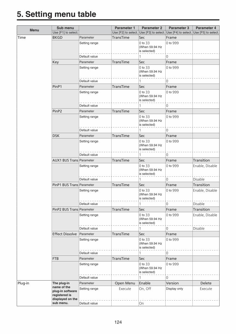
124
MenuSub menu Parameter 1 Parameter 2 Parameter 3 Parameter 4
Use[F1]toselect. Use[F2]toselect. Use[F3]toselect. Use[F4]toselect. Use[F5]toselect.
Time BKGD Parameter TransTime Sec Frame
Settingrange 0to33(When59.94Hzisselected)
0to999
Defaultvalue 1 0
Key Parameter TransTime Sec Frame
Settingrange 0to33(When59.94Hzisselected)
0to999
Defaultvalue 1 0
PinP1 Parameter TransTime Sec Frame
Settingrange 0to33(When59.94Hzisselected)
0to999
Defaultvalue 1 0
PinP2 Parameter TransTime Sec Frame
Settingrange 0to33(When59.94Hzisselected)
0to999
Defaultvalue 1 0
DSK Parameter TransTime Sec Frame
Settingrange 0to33(When59.94Hzisselected)
0to999
Defaultvalue 1 0
AUX1 BUS Trans Parameter TransTime Sec Frame Transition
Settingrange 0to33(When59.94Hzisselected)
0to999 Enable, Disable
Defaultvalue 1 0 Disable
PinP1 BUS Trans Parameter TransTime Sec Frame Transition
Settingrange 0to33(When59.94Hzisselected)
0to999 Enable, Disable
Defaultvalue 1 0 Disable
PinP2 BUS Trans Parameter TransTime Sec Frame Transition
Settingrange 0to33(When59.94Hzisselected)
0to999 Enable, Disable
Defaultvalue 1 0 Disable
Effect Dissolve Parameter TransTime Sec Frame
Settingrange 0to33(When59.94Hzisselected)
0to999
Defaultvalue 1 0
FTB Parameter TransTime Sec Frame
Settingrange 0to33(When59.94Hzisselected)
0to999
Defaultvalue 1 0
Plug-in The plug-in name of the plug-in software registered is displayed on the sub menu.
Parameter Open Menu Enable Version Delete
Settingrange Execute On, Off Displayonly Execute
Defaultvalue On
5. Setting menu table
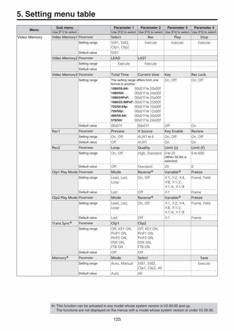
125
MenuSub menu Parameter 1 Parameter 2 Parameter 3 Parameter 4
Use[F1]toselect. Use[F2]toselect. Use[F3]toselect. Use[F4]toselect. Use[F5]toselect.
Video Memory Video Memory1 Parameter Select Rec Play Stop
Settingrange Still1, Still2, Clip1, Clip2
Execute Execute Execute
Defaultvalue Still1
Video Memory2 Parameter LEAD LAST
Settingrange Execute Execute
Defaultvalue
Video Memory3 Parameter Total Time Current time Key Rec Lock
Settingrange Thesettingrangediffersfromoneformattoanother.1080/59.94i: 00s01fto20s00f1080/50i: 00s01fto24s00f1080/24PsF: 00s01fto25s00f1080/23.98PsF: 00s01fto25s00f720/59.94p: 00s01fto10s00f720/50p: 00s01fto12s00f480/59.94i: 00s01fto20s00f576/50i: 00s01fto24s00f
On, Off On, Off
Defaultvalue 00s01f 00s01f Off On
Rec1 Parameter Preview V Source Key Enable Review
Settingrange On, Off AUX1to4 On, Off On, Off
Defaultvalue Off AUX1 On On
Rec2 Parameter Loop Quality Limit (s) Limit (f)
Settingrange On, Off High, Standard 0to20(When59.94iisselected)
0to600
Defaultvalue Off Standard 20 0
Clip1 Play Mode Parameter Mode Reverse Variable Freeze
Settingrange Lead, Last, Loop
On, Off ×1, ×2, ×4, ×8, ×1/2, ×1/4, ×1/8
Frame, Field
Defaultvalue Last Off ×1 Frame
Clip2 Play Mode Parameter Mode Reverse Variable Freeze
Settingrange Lead, Last, Loop
On, Off ×1, ×2, ×4, ×8, ×1/2, ×1/4, ×1/8
Frame, Field
Defaultvalue Last Off ×1 Frame
Trans Sync Parameter Clip1 Clip2
Settingrange Off, KEY ON, PinP1 ON, PinP2 ON, DSK ON, FTB ON
Off, KEY ON, PinP1 ON, PinP2 ON, DSK ON, FTB ON
Defaultvalue Off Off
Memory Parameter Mode Select Save
Settingrange Auto, Manual Still1, Still2, Clip1, Clip2, All
Execute
Defaultvalue Auto All
5. Setting menu table
:ThisfunctioncanbeactuatedinanymodelwhosesystemversionisV2.00.00andup.ThefunctionsarenotdisplayedonthemenuswithamodelwhosesystemversionisunderV2.00.00.

126
MenuSub menu Parameter 1 Parameter 2 Parameter 3 Parameter 4
Use[F1]toselect. Use[F2]toselect. Use[F3]toselect. Use[F4]toselect. Use[F5]toselect.
SD Card File1 Parameter Mode () Save Type File Name Save
Settingrange Load, Save, Init, Delete, No Card
Still1, Still2, Clip1, Clip2, Shot, Event, Set Up, All, Log
Execute
Defaultvalue No Card All
File2 Parameter Sort Format
Settingrange Newest, Oldest, Name
bmp, tga, png, jpg, tif, gif
Defaultvalue Name bmp
Card Information
Parameter Free Space
Settingrange 0 / 0
Defaultvalue Displayonly
Shot Memory Store Select Parameter BKGD Key PinP1 PinP2
Settingrange On, Off On,Off On, Off On, Off
Defaultvalue On On On On
Recall Select Parameter BKGD Key PinP1 PinP2
Settingrange On, Off On,Off On, Off On, Off
Defaultvalue On On On On
XPT Disable Parameter BKGD Key PinP1 PinP2
Settingrange On, Off On,Off On, Off On, Off
Defaultvalue Off Off Off Off
Register Parameter Page No. Name CopyTo ()
Settingrange 1to10 1to10 1to100
Defaultvalue 1 1 1
Path Parameter Effect PinP Bus Hue Path
Settingrange Cut, Dissolve Cut, Dissolve Short, Long, CW, CCW
Defaultvalue Dissolve Dissolve Short
MEM PVW Parameter Mode
Settingrange MEM-PVW, PGM
Defaultvalue PGM
5. Setting menu table

127
MenuSub menu Parameter 1 Parameter 2 Parameter 3 Parameter 4
Use[F1]toselect. Use[F2]toselect. Use[F3]toselect. Use[F4]toselect. Use[F5]toselect.
Event Memory Mark Parameter PAUSE CLIP GPI-Out
Settingrange On, Off Clip1, Clip2, Off GPI-O1toGPI-O19, Off
Defaultvalue Off Off Off
Event Duration Parameter minute second frame Set
Settingrange Execute
Defaultvalue 0 0 0
Total Duration Parameter minute second frame Set
Settingrange Execute
Defaultvalue 0 0 0
Timeline Parameter View
Settingrange Normal, Wide
Defaultvalue Wide
Run Parameter Run Mode
Settingrange Repeat, Loop
Defaultvalue Repeat
Store Select Parameter BKGD Key PinP1 PinP2
Settingrange On, Off On,Off On, Off On, Off
Defaultvalue On On On On
Recall Select Parameter BKGD Key PinP1 PinP2
Settingrange On, Off On, Off On, Off On, Off
Defaultvalue On On On On
XPT Disable Parameter BKGD Key PinP1 PinP2
Settingrange On, Off On,Off On, Off On, Off
Defaultvalue Off Off Off Off
Register Parameter Page No. Name CopyTo ()
Settingrange 1to10 1to10 1to100
Defaultvalue 1 1 1
Path Parameter Effect PinP Bus Trans Path Hue Path
Settingrange Cut, Dissolve Cut, Dissolve Linear, Step Short, Long, CW, CCW, Step
Defaultvalue Dissolve Dissolve Linear CW
MEM PVW Parameter Mode
Settingrange MEM-PVW, PGM
Defaultvalue PGM
5. Setting menu table

128
MenuSub menu Parameter 1 Parameter 2 Parameter 3 Parameter 4
Use[F1]toselect. Use[F2]toselect. Use[F3]toselect. Use[F4]toselect. Use[F5]toselect.
XPT XPT Assign 1/6 Parameter XPT1Signal XPT2Signal XPT3Signal XPT4Signal
Settingrange SDI IN1to8, DVI IN, IN-A1, IN-A2, IN-B1, IN-B2, Black, CBGD1, CBGD2, CBAR, Still1V, Still1K, Still2V, Still2K, Clip1V, Clip1K, Clip2V, Clip2K, MEM-PVW, CLN, KeyOut, None
Defaultvalue Black SDI IN1 SDI IN2 SDI IN3
XPT Assign 2/6 Parameter XPT5Signal XPT6Signal XPT7Signal XPT8Signal
Settingrange ThesettingrangeisthesameasfortheXPTAssign1/6submenu.
Defaultvalue SDI IN4 SDI IN5 SDI IN6 SDI IN7
XPT Assign 3/6 Parameter XPT9Signal XPT10Signal XPT11Signal XPT12Signal
Settingrange ThesettingrangeisthesameasfortheXPTAssign1/6submenu.
Defaultvalue SDI IN8 DVI IN IN-A1 None
XPT Assign 4/6 Parameter XPT13Signal XPT14Signal XPT15Signal XPT16Signal
Settingrange ThesettingrangeisthesameasfortheXPTAssign1/6submenu.
Defaultvalue IN-A2 IN-B1 IN-B2 CBAR
XPT Assign 5/6 Parameter XPT17Signal XPT18Signal XPT19Signal XPT20Signal
Settingrange ThesettingrangeisthesameasfortheXPTAssign1/6submenu.
Defaultvalue CBGD1 Still1V Still2V None
XPT Assign 6/6 Parameter XPT21Signal XPT22Signal XPT23Signal XPT24Signal
Settingrange ThesettingrangeisthesameasfortheXPTAssign1/6submenu.
Defaultvalue KeyOut CLN None None
XPT Setting Parameter Shift Shift-Lock
Settingrange Off, Right, Left On, Off
Defaultvalue Right Off
XPT Switch Parameter Timing
Settingrange Any, Field1, Field2
Defaultvalue Any
5. Setting menu table

129
MenuSub menu Parameter 1 Parameter 2 Parameter 3 Parameter 4
Use[F1]toselect. Use[F2]toselect. Use[F3]toselect. Use[F4]toselect. Use[F5]toselect.
Multi View Display MV Split Parameter Split
Settingrange 4Split, 5-aSplit, 5-bSplit, 6-aSplit, 6-bSplit, 9Split, 10-aSplit, 10-bSplit, 16Split
Defaultvalue 10-aSplit
MV Pattern 1/4 Parameter Pos1Signal Pos2Signal Pos3Signal Pos4Signal
Settingrange SDI IN1to8, DVI IN, IN-A1, IN-A2, IN-B1, IN-B2, CBGD1, CBGD2, Still1V, Still1K, Still2V, Still2K, Clip1V, Clip1K, Clip2V, Clip2K, PGM, PVW, MEM-PVW, Key Out, AUX1to4, Clock
Defaultvalue PGM PVW SDI IN1 SDI IN2
MV Pattern 2/4 Parameter Pos5Signal Pos6Signal Pos7Signal Pos8Signal
Settingrange ThesettingrangeisthesameasfortheMVPattern1/4submenu.
Defaultvalue SDI IN3 SDI IN4 SDI IN5 SDI IN6
MV Pattern 3/4 Parameter Pos9Signal Pos10Signal Pos11Signal Pos12Signal
Settingrange ThesettingrangeisthesameasfortheMVPattern1/4submenu.
Defaultvalue SDI IN7 SDI IN8 DVI IN Still1V
MV Pattern 4/4 Parameter Pos13Signal Pos14Signal Pos15Signal Pos16Signal
Settingrange ThesettingrangeisthesameasfortheMVPattern1/4submenu.
Defaultvalue Still2V Clip1V Clip2V AUX1
MV Frame Parameter Frame Character Label Tally
Settingrange LUM0%, LUM25%, LUM50%, LUM75%, LUM100%, Off
LUM0%, LUM25%, LUM50%, LUM75%, LUM100%, Off
On, Off Red, Red+Green, Off
Defaultvalue LUM75% LUM75% On Red+Green
Display Parameter Level Meter Input Status Marker Marker Size
Settingrange On, Off On, Off 4:3, 16:9, Off 80to100%
Defaultvalue Off On Off 95%
5. Setting menu table

130
MenuSub menu Parameter 1 Parameter 2 Parameter 3 Parameter 4
Use[F1]toselect. Use[F2]toselect. Use[F3]toselect. Use[F4]toselect. Use[F5]toselect.
Input Input Parameter Select ()
Settingrange SDI IN1to8, DVI IN, IN-A1, IN-A2, IN-B1, IN-B2
Defaultvalue SDI IN1
Input (SDI) / X ()
SDIIN1toSDIIN8,INA1,INA2,INB1orINB2isdisplayedintheXpart.Thematerialname
(upto10characters)isdisplayedinthepart.
FS Parameter FS Mode Delay
Settingrange On, Off Normal, Dot by Dot, Up Convert, Auto(OnlySDIIN5toSDIIN8arecoveredbythe“UpConvert”and“Auto”modes.)
0to8f(OnlySDIIN7andSDIIN8areinvolvedhere.)
Defaultvalue On SDIIN1toSDIIN4: Normal
SDIIN5toSDIIN8: Auto
0f
Freeze Parameter Select Freeze
Settingrange Frame, Field On, Off
Defaultvalue Frame Off
Name Parameter Type Name
Settingrange Default, User
Defaultvalue Default
Up Converter1 Parameter Scale Move Detect Sharp Size
(SDIIN5toSDIIN8,INA1,INA2,INB1,andINB2only)
Settingrange Squeeze, Edge Crop, Letter Box
1to5 1to5 100to110
Defaultvalue Squeeze 3 3 100
Up Converter2 Parameter Edge Crop Pos Limiter
(SDIIN5toSDIIN8,INA1,INA2,INB1,andINB2only)
Settingrange Center, Right, Left
Off, 108, 104, 100(OnlyINA1,INA2,INB1andINB2areinvolvedhere.)
Defaultvalue Center Off
Video Process1 Parameter Video Process Y-Gain Pedestal
Settingrange On, Off 0.0to200.0 �20.0to20.0
Defaultvalue Off 100.0 0.0
Video Process2 Parameter C-Gain Hue Copy From ()
Settingrange 0.0to200.0 0.0to359.9 SDI IN1toSDI IN8
Defaultvalue 100.0 0.0 DefaultvaluesvarydependingontheselectionsoftheSelectitemsintheInputsubmenu.
5. Setting menu table
: When the Select item is SDI IN1: SDI IN2 When the Select item is other than SDI IN1: SDI IN1

131
MenuSub menu Parameter 1 Parameter 2 Parameter 3 Parameter 4
Use[F1]toselect. Use[F2]toselect. Use[F3]toselect. Use[F4]toselect. Use[F5]toselect.
Input (Analog) / X ()
INA1,INA2,INB1orINB2isdisplayedintheXpart.Thematerialname
(upto10characters)isdisplayedinthepart.
FS Parameter FS Mode
Settingrange On, Off Normal, Dot by Dot, Up Convert
Defaultvalue On Normal
Freeze Parameter Select Freeze
Settingrange Frame, Field On, Off
Defaultvalue Frame Off
Name Parameter Type Name
Settingrange Default, User
Defaultvalue Default
Up Converter1 Parameter Scale Move Detect Sharp Size
Settingrange Squeeze, Edge Crop, Letter Box
1to5 1to5 100to110
Defaultvalue Squeeze 3 3 100
Up Converter2 Parameter Edge Crop Pos Limiter
Settingrange Center, Right, Left
Off, 108, 104, 100
Defaultvalue Center Off
Video Process Parameter Gain
Settingrange �30to30
Defaultvalue 0
Input (DVI) / X ()
DVIIN,INA1,INA2,INB1orINB2isdisplayedintheXpart.Thematerialname
(upto10characters)isdisplayedinthepart.
Freeze Parameter Select Freeze
Settingrange Frame, Field On, Off
Defaultvalue Frame Off
Name Parameter Type Name
Settingrange Default, User
Defaultvalue Default
DVI Input Parameter Mode Scale Auto ()
Settingrange Digital, Analog(EnabledwhentheAV-HS04M3optionboardhasbeenconnected.)
Fit-V, Fit-H, Full Black, White (EnabledwhentheAV-HS04M3optionboardhasbeenconnected.), Init
Defaultvalue Digital Full Black
DVI Phase Parameter Clk Phs H-Pos V-Pos
(EnabledwhentheAV-HS04M3optionboardhasbeenconnected.)
Settingrange �16to15 �100to100 �100to100
Defaultvalue 0 0 0
DVI Status Displayonly Size Dot Clock H-Frequency V-Frequency
x .MHz .kHz .Hz
5. Setting menu table

132
MenuSub menu Parameter 1 Parameter 2 Parameter 3 Parameter 4
Use[F1]toselect. Use[F2]toselect. Use[F3]toselect. Use[F4]toselect. Use[F5]toselect.
Input (Composite) / X ()
INA1,INA2,INB1orINB2isdisplayedintheXpart.Thematerialname
(upto10characters)isdisplayedinthepart.
FS Parameter FS Mode
Settingrange On, Off Dot by Dot, Up Convert(Enabledwhenthesystemformatissetto1080/59.94i,1080/24PsF,1080/23.98PsFand720/59.94p.)
Defaultvalue On Up Convert
Freeze Parameter Select Freeze
Settingrange Frame, Field On, Off
Defaultvalue Frame Off
Name Parameter Type Name
Settingrange Default, User
Defaultvalue Default
Up Converter1 Parameter Scale Move Detect Sharp Size
Settingrange Squeeze, Edge Crop, Letter Box
1to5 1to5 100to110
Defaultvalue Squeeze 3 3 100
Up Converter2 Parameter Edge Crop Pos Limiter
Settingrange Center, Right, Left
Off, 108, 104, 100
Defaultvalue Center Off
Video Process Parameter Gain Chroma Ped Hue
Settingrange �30to30 �8to7 �100to100 �30to30(Enabledwhenthesystemformatissetto1080/59.94i,720/59.94pand480/59.94i.)
Defaultvalue 0 0 0 0
5. Setting menu table

133
MenuSub menu Parameter 1 Parameter 2 Parameter 3 Parameter 4
Use[F1]toselect. Use[F2]toselect. Use[F3]toselect. Use[F4]toselect. Use[F5]toselect.
Output Output Parameter Select () SDI Limit
Settingrange SDI OUT1to5, DVI OUT, OUT-A1, OUT-A2, OUT-B1, OUT-B2
Off, 108, 104, 100
Defaultvalue SDI OUT1 Off
Output (SDI) / Y
SDIOUT1toSDIOUT5,OUTA1,OUTA2,OUTB1orOUTB2isdisplayedintheYpart.(OUTA1,OUTA2,OUTB1andOUTB2takeeffectwhentheAV-HS04M7boardhasbeenconnected.)
Assign Parameter Source Mode
Settingrange PGM, PVW, CLN, AUX1to4, MV, KeyOut, MEM-PVW
Normal, Down Convert(“DownConvert”takeseffectwhenAV-HS04M7isconnected.)
Defaultvalue PGM(OUT1), PVW(OUT2), AUX1(OUT3), AUX2(OUT4), AUX3(OUT5), AUX1(OUTA1), AUX2(OUTA2), AUX3(OUTB1), AUX4(OUTB2)
Normal
Down Converter
Parameter Scale Delay Sharp
(EnabledwhentheAV-HS04M7optionboardhasbeenconnected.)
Settingrange Squeeze, Edge Crop, Letter Box
90H(75H), 1F 1to5
Defaultvalue Squeeze 90H(75H) 3
Output (Analog) / Y
OUTA1,OUTA2,OUTB1orOUTB2isdisplayedintheYpart.(OUTA1,OUTA2,OUTB1andOUTB2takeeffectwhentheAV-HS04M4boardhasbeenconnected.OUTA2andOUTB2takeeffectwhentheAV-HS04M5boardhasbeenconnected.)
Assign Parameter Source
Settingrange PGM, PVW, CLN, AUX1to4, MV, Key Out, MEM-PVW
Defaultvalue AUX1(OUTA1), AUX2(OUTA2), AUX3(OUTB1), AUX4(OUTB2)
5. Setting menu table

134
MenuSub menu Parameter 1 Parameter 2 Parameter 3 Parameter 4
Use[F1]toselect. Use[F2]toselect. Use[F3]toselect. Use[F4]toselect. Use[F5]toselect.
Output (DVI-D) / DVI OUT
Assign Parameter Source Move Detect
Settingrange PGM, PVW, CLN, AUX1to4, MV, Key Out, MEM-PVW
1to5
Defaultvalue MV 3
DVI Output Parameter Size () Scale
Settingrange Auto, XGA, WXGA, SXGA, WSXGA+, UXGA, WUXGA, 1080/59.94i, 1080/59.94p, 720/59.94p, 720/50p, 1080/50p, 1080/50i
Fit-V, Fit-H, Full, Fullx80%, Fullx90%
Defaultvalue Auto Full
Output (DVI-I) / Y
OUTA1orOUTB1isdisplayedintheYpart.(IttakeseffectwhentheAV-HS04M5boardhasbeenconnected.)
Assign Parameter Source Move Detect
Settingrange PGM, PVW, CLN, AUX1to4, MV, Key Out, MEM-PVW
1to5
Defaultvalue AUX1(OUTA1), AUX3(OUTB1)
3
DVI Output Parameter Mode Size Scale
Settingrange Digital, Analog Analog Auto, XGA,WXGA, SXGA
Digital Auto, XGA,WXGA, SXGA,WSXGA+,UXGA, WUXGA
Fit-V, Fit-H, Full, Fullx80%, Fullx90%
Defaultvalue Digital Auto Full
5. Setting menu table

135
MenuSub menu Parameter 1 Parameter 2 Parameter 3 Parameter 4
Use[F1]toselect. Use[F2]toselect. Use[F3]toselect. Use[F4]toselect. Use[F5]toselect.
Config Operate Parameter Bus Mode Key Link Time Unit Delegation
Settingrange A/B, PGM-A/PST-B, PGM-B/PST-A
Off, DSK, PinP1, PinP2, PinP1/2
Sec, Frame On, Off
Defaultvalue PGM-A/PST-B Off Sec On
Assign Parameter FTB Source CLN
Settingrange Still1, Still2, Clip1, Clip2, CBGD1, CBGD2, White, Black
Key, DSK
Defaultvalue Black Key
Latency Parameter BKGD Key
Settingrange 1F Fix, Minimum
1F Fix, Minimum
Defaultvalue Minimum Minimum
LCD BL Parameter Light () Adjust
Settingrange On, Off, 60, 120, 180
80to150%
Defaultvalue On 100%
Button Illumination
Parameter Illumination Adjust
Settingrange On, Off 80to150%
Defaultvalue On 100%
WFM Parameter Style Mode
Settingrange Parade, Overlay YPbPr, RGB, Y
Defaultvalue Parade YPbPr
Vector Parameter Bar Target
Settingrange 75%, 100%
Defaultvalue 100%
User Button1 Parameter User1 User2 User3 User4
Settingrange KEY PVW, PinP PVW, PinP1PVW, PinP2PVW, DSK PVW, GPII-EN, GPIO-EN, SHIFT, AUX Trans, PinP Trans, EFF DSLV, None
Defaultvalue KEY PVW PinP PVW DSK PVW PinP Trans
User Button2 Parameter User5 User6 User7 User8
Settingrange ThesettingrangeisthesameasfortheUserButton1submenu.
Defaultvalue AUX Trans EFF DSLV SHIFT None
5. Setting menu table

136
MenuSub menu Parameter 1 Parameter 2 Parameter 3 Parameter 4
Use[F1]toselect. Use[F2]toselect. Use[F3]toselect. Use[F4]toselect. Use[F5]toselect.
Config GPI-In Setting Parameter GPI-In Enable AUX Sel
Settingrange On, Off AUX1to4
Defaultvalue On AUX1
GPI-In Port 1/2 Parameter Port1Assign Port2Assign Port3Assign Port4Assign
Settingrange AUTO, CUT, KEY ON, DSK ON, PinP1 ON, PinP2 ON, FTB, BKGD AUTO, BKGD CUT, KEY AUTO, KEY CUT, REC Still1, REC Still2, REC Clip1, PLAY Clip1, STOP Clip1, REC Clip2, PLAY Clip2, STOP Clip2, AUX XPT1to24, RED Tly DSBL, GRN Tly DSBL, AUX Tly DSBL, No Assign
Defaultvalue No Assign No Assign No Assign No Assign
GPI-In Port 2/2 Parameter Port5Assign Port6Assign Port7Assign Port8Assign
Settingrange ThesettingrangeisthesameasfortheGPI-InPort1/2submenu.
Defaultvalue No Assign No Assign No Assign No Assign
GPI-Out Setting
Parameter GPI-Out Enable AUX Tly Sel
Settingrange On, Off AUX1to4
Defaultvalue On AUX1
GPI-Out Port 1/5
Parameter Port1Assign Port2Assign Port3Assign Port4Assign
Settingrange AUTO, CUT, KEY ON, DSK ON, PinP1 ON, PinP2 ON, FTB ON, BKGD AUTO, BKGD CUT, KEY AUTO, KEY CUT, KEY Trans, DSK Trans, PinP1Trans, PinP2Trans, FTB Trans, RED Tly1to13, GRN Tly1to13, AUX Tly1to13, Event MEM, No Assign
Defaultvalue No Assign No Assign No Assign No Assign
GPI-Out Port 2/5
Parameter Port5Assign Port6Assign Port7Assign Port8Assign
Settingrange ThesettingrangeisthesameasfortheGPI-OutPort1/5submenu.
Defaultvalue No Assign No Assign No Assign No Assign
GPI-Out Port 3/5
Parameter Port9Assign Port10Assign Port11Assign Port12Assign
Settingrange ThesettingrangeisthesameasfortheGPI-OutPort1/5submenu.
Defaultvalue No Assign No Assign No Assign No Assign
GPI-Out Port 4/5
Parameter Port13Assign Port14Assign Port15Assign Port16Assign
Settingrange ThesettingrangeisthesameasfortheGPI-OutPort1/5submenu.
Defaultvalue No Assign No Assign No Assign No Assign
GPI-Out Port 5/5
Parameter Port17Assign Port18Assign Port19Assign
Settingrange ThesettingrangeisthesameasfortheGPI-OutPort1/5submenu.
Defaultvalue No Assign No Assign No Assign
COM-Port Parameter Mode ()
Settingrange 1to3
Defaultvalue 1
System Menu Parameter Lock
Settingrange On, Off
Defaultvalue Off
5. Setting menu table

137
MenuSub menu Parameter 1 Parameter 2 Parameter 3 Parameter 4
Use[F1]toselect. Use[F2]toselect. Use[F3]toselect. Use[F4]toselect. Use[F5]toselect.
System /Locked
(Whenlocked)
(Message) DisplayonlySystem menu is locked
System /Unlocked
(Whenunlocked)
Format Parameter Format () Hi Resolution 16:9 Squeeze
Settingrange 1080/59.94i, 1080/50i, 1080/24PsF, 1080/23.98PsF, 720/59.94p, 720/50p, 480/59.94i, 576/50i
On, Off(SelectionenabledwhenSDformatisused)
On, Off(SelectionenabledwhenSDformatisused)
Defaultvalue 1080/59.94i Off Off
Output Phase Parameter System H-Phase V-Phase
Settingrange 0H, 1H Thesettingrangediffersfromoneformattoanother.
1080/59.94i: �1100to10991080/50i: �1320to13191080/24PsF: �1375to13741080/23.98PsF: �1375to1374720/59.94p: �825to824720/50p: �990to989480/59.94i: �429to428576/50i: �432to431
�100to100
Defaultvalue 0H 0 0
Reference Parameter Sync () BB Setup Gen Lock
Settingrange BB, BB Advanced, Tri-level sync, Internal
0IRE, 7.5IRE Locked, UnLock
Defaultvalue BB 7.5IRE UnLock
Ancillary Parameter AUX PGM PVW MV
Settingrange On, Off On, Off On, Off PGM, PVW, Off
Defaultvalue Off Off Off Off
Alarm Parameter Power Fan Temperature
Displayonly Alarm, No Alarm
Alarm, No Alarm
Alarm, No Alarm
Initial Parameter Initial () Fader Initial
Settingrange Mode A, Mode B
Execute
Defaultvalue Mode A
5. Setting menu table

138
MenuSub menu Parameter 1 Parameter 2 Parameter 3 Parameter 4
Use[F1]toselect. Use[F2]toselect. Use[F3]toselect. Use[F4]toselect. Use[F5]toselect.
System /Unlocked
(Whenunlocked)
Network1 Parameter IP Address
Settingrange 0to255
Defaultvalue 192.168.0.8
Network2 Parameter Subnet Mask
Settingrange 0to255
Defaultvalue 255.255.255.0
Network3 Parameter Default Gateway
Settingrange 0to255
Defaultvalue 192.168.0.1
Network4 Parameter MAC Address
Displayonly Displayonly
Date Parameter Year Month Date Set
Settingrange 2011to2035 1to12 1to31 Execute
Defaultvalue � � �
Time Parameter Hour Minute Second Set
Settingrange 0to23 0to59 0to59 Execute
Defaultvalue � � �
Main Version Parameter System Version Module Type Select Version
Settingrange Versionnumber Soft, FPGA Soft Main1, Main2, BKGD, KEY, PinP, DSK, TIME, Plugin, VMEM, Memory, XPT/MV, Input, Output, Config, System, BKGDPat, XPTStat, HsifLibrary
FPGA Main1, Main2, SDI, DVI, Control, Panel
Versionnumber
Defaultvalue Soft Main1
Option Version Parameter Select Board Version
Settingrange SLOT A, SLOT B SDI-IN, Ana-IN, DVI-IN, DVID-IN, SDI-OUT, Ana-OUT, D/A-OUT, Csit-IN, None
Versionnumber
Defaultvalue SLOT A
5. Setting menu table

139
Appendix (glossary)
Definedbelowarethetermsusedinthismanual.
Word Explanation
AB Bus system Abuscontrolmode.Byexecutingatransition,theAbusandBbussignalsareoutputtotheprogramimagesalternately.
Ancillary Data Theauxiliarydataotherthanthevideosignalswhichistransmittedinsidethedatastreamofthevideoserialinterface.ThedatasuperimposedontheverticalblankingperiodisreferredtoastheVancillarydata(VANC).
Aspect ratio Theratiobetweenthehorizontalandverticaldimensionsofanimageorscreen.Itis16:9fortheHDformatand4:3fortheSDformat.
AUX[Auxiliary Bus]
Asparebuswhichcanbeswitchedbysignalsotherthanthemainlineoutputsignals.
AVDL[Automatic Video Delay Line]
Afunctiontoautomaticallyadjusttheinputimagesignalphasetothehorizontalsynchronizationreferencesignalphase.
BB[Black burst]
Theblackburstsignal.Afull-screenblacklevelcompositesignalwhichisusedasthereferencesignalforgen-lock.
Border Theareaormarginthatisaddedtotheedgeofawipeorkey.Itswidthandcolorcanbeadjusted.Thedefocusingoftheareaaroundaborderisreferredtoasthesofteffect.
Chroma key Thisreferstothefunctionforcreatingthekeysignalsbasedonthecolorinformationofthevideosignalsandcombiningthekeys.
Clip Thethresholdleveloftheluminancewhenkeysignalsarecreatedfromakeysource.
Color Background Thesignalswhichareoutputfromtheinternalcolorgeneratorandusedasthebackgroundimage.
Cut Thisreferstotheeffectwherethedisplayisinstantlyswitchedtothenextimage.
Density Aparameterwhichisusedtoadjustthedensityofthekeysignals.
Dot by Dot Thistreatsimagesasactualsize(1)images.WithPinP,itallowsSDimagestobecombinedwithHDimageswithnoaccompanyingdeteriorationintheimagesthemselves.
Down Converter ThisisthefunctionthatconvertsmaterialintheHDformatintotheSDformat.
DSK [Downstream Key] Thisreferstothekeycombinationprocesswhichisperformedattheendofthemixeffect.Thekeyisalwayscombinedwiththeforemostimage.
DVE [Digital Video Effect] Thisreferstothetransitionpatternsaccompanyingsizereductionsorslideeffects.
DVI[Digital Visual Interface]
Adigitalvideointerfacestandard.DVI-Icanhandlebothdigitalsignalsandanalogsignals.
Embedded Audio Thisreferstotheaudiodatapacketswhicharetransferredinsidethedatastreamofthevideoserialinterface.
Flip Flop system(PGM/PST system)
Abuscontrolmode.Thesignalsselectedbytheprogrambusarealwaysoutputastheprogramimages.Byexecutingatransition,theprogrambusandpresetbussignalsareswitchedover.
Flying Key ThisfunctionusesDVEeffectstomove,expandorreducekeysignals.
Frame Synchronizer Afunctionwhichmatchesthesynchronizationofnon-synchronizedvideoinputsignals.
Freeze Afunctionwhichcontinuesthedisplayofthesameimage,creatingtheimpressionthattheimagehasbeen“frozen”.
FTB [Fade to Black] Thisistheeffectwherethebackgroundimageisfadedouttotheblackscreen.
Genlock Afunctionforsynchronizingthevideosignalsusinganexternalsyncsignalasthereference.

140
Word Explanation
GPI[General Purpose Interface]
Interfacesignalswhichcontrolautotransitionfromanexternalsource.
Hue Thecolortoneofthevideosignals.
IRE Aunitusedforvideosignallevels.Thesetuplevel(blacklevel)ofthesignalsisexpressedas0IRE,7.5IRE,etc.
Key Edge Theborderorshadowaddedtotheedgesofkeys.
Key Fill Thesignalthatuseskeycombinationprocessingtofillintheareasleftblankbythekeysignals.
Key Gain Aparameterwhichisusedtoadjusttheamplitudeofthekeysignals.
Key Invert Afunctionwhichinvertsthekeysignals.
Key Mask Thisisthefunctionthatspecifiestheareaforkeycombinationusingtheboxpattern,etc.Whenonlypartoftheareaofthekeysignalsisused,keycombinationisexecutedwiththeunnecessaryareamasked.
Key Source Thevideosignalsforcreatingthekeysignals.
Linear Key Thefunctionwhichcombineskeysusingmonochromekeysignalswithgradationsinitsoutlinesasareference.
Lum[Luminance]
Thebrightnessportionofthevideosignals.
Luminance Key Thefunctionwhichcreateskeysignalsbasedontheluminance(brightness)informationofthevideosignalstocombinekeys.
ME[Mix Effect]
Avideoeffectdevicewhichcombinesanumberofvideosignalstocreatemix,wipe,keyandothervideosignals.
Mix Thepicture-changingeffectproducedbyoverlappingoneimagewiththenext.Itisalsoreferredtoas“dissolve”.
Multi View Display Thisfunctioncombinesmultiplematerialsanddisplaysthemononescreen.PGM,PVWandtheinputmaterialcanbepreviewedatthesametimeonasinglescreen.
OSD [On Screen Display] Thisfunctionenablessettingstobeperformedonthemenuscreenswhicharedisplayedinthemonitoroutput.
PinP [Picture in Picture] Thisfunctioncombinesasubscreenimagewiththebackgroundimage.
PVW[Preview]
Thefunctionforcheckingaheadoftimetheimagewhichwillbeoutputafterthenexttransition.TheimageisoutputfromthePVWsystem.
PGM[Program Bus]
Thebuswhichalwayscarriestheprogramoutputsignals.
PST[Preset Bus]
Thebuswhichcarriestheprogramoutputsignalsafterthenextbackgroundtransition.
RS-422 Aserialinterfacestandard.Itistheinterfaceusedtocontroltheswitcherfromaneditororotherexternaldevice.
Sat[Saturation]
Thisreferstotheintensityofthecolorchrominancelevelofvideosignals.
SDI[Serial Digital Interface]
ThestandardbywhichvideosignalsinvariousSDandHDformatsaretransmittedalongasinglecoaxialcable.
Self Key Afunctionthatcreateskeysignalsfromkeyfillsignalsforcombiningkeys.
Setup Data Thememoryinwhichthecontrolpanelstatusescanbesavedandrecalled.Thebuttonselectionstatusesaswellastheborder,colorandothersettinginformationcanbesavedinthismemory.
Appendix (glossary)

141
Word Explanation
Tally Thesignalwhichoutputstheprogramoutputstatusesoftheinputsignalstoanexternaldevice.TheLEDthatindicatestheprogramoutputstatusonthecontrolpanelisalsoreferredtoastally.
Transition Afunctionthatswitchesfromoneimagetoanother.Wipe,mixandothereffectsareavailablefortheimagesduringswitching.
Tri-level Sync ThesyncsignalusedforHDformats.
Trimming Thisisthefunctionthateliminatestheunnecessarypartsatthetop,bottom,leftand/orrightoftheimageswhicharecombinedusingthePinPfunction.
Up Converter ThisisthefunctionthatconvertsmaterialintheSDformatintotheHDformatwhichyieldsahighresolution.
Video Memory Thisisthememoryinwhichtheimages(stillimagesandmovingimages)withkeysignalscanbestored.
Wipe Avideoeffectinwhichoneimageisgraduallyreplacedbyanotherastheboundarybetweenthetwoismovedusingapreselectedpattern.
Appendix (glossary)

142
BMM Background ............................................. 117
3DModify........................................................... 117Border................................................................. 117BorderColor....................................................... 117Modify................................................................. 117SQPosition......................................................... 117WIPEPosition..................................................... 117
CMM Chroma Key ............................................. 120
Adjust................................................................. 120AutoCompute..................................................... 120FineTuning.......................................................... 120Sample............................................................... 120
MM Color Background ................................... 118CBGD1Main...................................................... 118CBGD1Move..................................................... 118CBGD1Sub........................................................ 118CBGD1Wash..................................................... 118CBGD1Wave..................................................... 118CBGD2Main...................................................... 118CBGD2Move..................................................... 118CBGD2Sub........................................................ 118CBGD2Wash..................................................... 118CBGD2Wave..................................................... 118
MM Config ...................................................... 135Assign................................................................. 135ButtonIllumination.............................................. 135COM-Port........................................................... 136GPI-InPort1/2.................................................... 136GPI-InPort2/2.................................................... 136GPI-InSetting..................................................... 136GPI-OutPort1/5................................................. 136GPI-OutPort2/5................................................. 136GPI-OutPort3/5................................................. 136GPI-OutPort4/5................................................. 136GPI-OutPort5/5................................................. 136GPI-OutSetting.................................................. 136Latency............................................................... 135LCDBL............................................................... 135Operate.............................................................. 135SystemMenu...................................................... 136UserButton1...................................................... 135UserButton2...................................................... 135Vector................................................................. 135WFM................................................................... 135
DMM DSK .......................................................... 123
Adjust................................................................. 123DSK.................................................................... 123Edge1................................................................. 123Edge2................................................................. 123EdgeColor......................................................... 123FillMatt............................................................... 123Mask................................................................... 123MaskAdjust........................................................ 123
EMM Event Memory ......................................... 127
EventDuration.................................................... 127Mark................................................................... 127MEMPVW.......................................................... 127Path.................................................................... 127RecallSelect...................................................... 127Register.............................................................. 127Run..................................................................... 127StoreSelect........................................................ 127Timeline.............................................................. 127TotalDuration..................................................... 127XPTDisable........................................................ 127
IMM Input ......................................................... 130
Input................................................................... 130
MM Input (Analog) ......................................... 131Freeze................................................................ 131FS....................................................................... 131Name.................................................................. 131UpConverter1.................................................... 131UpConverter2.................................................... 131VideoProcess.................................................... 131
MM Input (Composite) ................................... 132Freeze................................................................ 132FS....................................................................... 132Name.................................................................. 132UpConverter1.................................................... 132UpConverter2.................................................... 132VideoProcess.................................................... 132
MM Input (DVI) ................................................ 131DVIInput............................................................. 131DVIPhase........................................................... 131DVIStatus........................................................... 131Freeze................................................................ 131Name.................................................................. 131
Index

143
MM Input (SDI) ................................................ 130Freeze................................................................ 130FS....................................................................... 130Name.................................................................. 130UpConverter1.................................................... 130UpConverter2.................................................... 130VideoProcess1.................................................. 130VideoProcess2.................................................. 130
KMM Key ........................................................... 119
3DModify........................................................... 119Adjust................................................................. 119Edge1................................................................. 119Edge2................................................................. 119EdgeColor......................................................... 119FillMatte............................................................. 119FlyingKey........................................................... 119Key..................................................................... 119KeyPriority......................................................... 120Mask................................................................... 120MaskAdjust........................................................ 120SQPosition......................................................... 119Transition............................................................ 119WIPEPosition..................................................... 119
MMM Multi View Display ................................... 129
Display................................................................ 129MVFrame........................................................... 129MVPattern1/4.................................................... 129MVPattern2/4.................................................... 129MVPattern3/4.................................................... 129MVPattern4/4.................................................... 129MVSplit.............................................................. 129
OMM Output ...................................................... 133
Output................................................................. 133
MM Output (Analog) ...................................... 133Assign................................................................. 133
MM Output (DVI-D) ......................................... 134Assign................................................................. 134DVIOutput.......................................................... 134
MM Output (DVI-I) ........................................... 134Assign................................................................. 134DVIOutput.......................................................... 134
MM Output (SDI) ............................................. 133Assign................................................................. 133DownConverter.................................................. 133
PMM PinP1 ........................................................ 121
Border................................................................. 121BorderColor....................................................... 121PinP.................................................................... 121Position............................................................... 121Sync................................................................... 121Trim..................................................................... 121TrimAdjust.......................................................... 121
MM PinP2 ........................................................ 122Border................................................................. 122BorderColor....................................................... 122PinP.................................................................... 122Position............................................................... 122Sync................................................................... 122Trim..................................................................... 122TrimAdjust.......................................................... 122
MM Plug-in ...................................................... 124
SMM SD Card .................................................... 126
CardInformation................................................. 126File1.................................................................... 126File2.................................................................... 126
MM Shot Memory ........................................... 126MEMPVW.......................................................... 126Path.................................................................... 126RecallSelect...................................................... 126Register.............................................................. 126StoreSelect........................................................ 126XPTDisable........................................................ 126
MM System ..................................................... 137Alarm.................................................................. 137Ancillary.............................................................. 137Date.................................................................... 138Format................................................................ 137Initial................................................................... 137MainVersion....................................................... 138Network1............................................................ 138Network2............................................................ 138Network3............................................................ 138Network4............................................................ 138OptionVersion.................................................... 138OutputPhase..................................................... 137Reference........................................................... 137Time................................................................... 138
Index

144
TMM Time ......................................................... 124
AUX1BUSTrans................................................ 124BKGD................................................................. 124DSK.................................................................... 124EffectDissolve.................................................... 124FTB..................................................................... 124Key..................................................................... 124PinP1.................................................................. 124PinP1BUSTrans................................................ 124PinP2.................................................................. 124PinP2BUSTrans................................................ 124
VMM Video Memory ......................................... 125
Clip1PlayMode................................................. 125Clip2PlayMode................................................. 125Memory.............................................................. 125Rec1................................................................... 125Rec2................................................................... 125TransSync.......................................................... 125VideoMemory1.................................................. 125VideoMemory2.................................................. 125VideoMemory3.................................................. 125
XMM XPT ........................................................... 128
XPTAssign1/6................................................... 128XPTAssign2/6................................................... 128XPTAssign3/6................................................... 128XPTAssign4/6................................................... 128XPTAssign5/6................................................... 128XPTAssign6/6................................................... 128XPTSetting........................................................ 128XPTSwitch......................................................... 128
Index

145
Memo

2011