Model No. NTL07806 - Appliance Parts | Replacement … No. NTL07806.2 Serial No. Find the serial...
32
Model No. NTL07806.2 Serial No. Find the serial number in the location shown below. Write the serial number in the space above for reference. QUESTIONS? As a manufacturer, we are com- mired to providing complete customer satisfaction. If you have questions, or if parts are damaged or missing, PLEASE CONTACT OUR CUSTOMER SERVICE DEPARTMENT DIRECTLY. CALL TOLL-FREE: 1-888-825-2588 Mon.-Fri., 6 a.m.-6 p.m. MST ON THE WEB: www.nordictrackservice.com CAUTION Read all precautions and Instruc- tions in this manual before using this equipment. Save this manual for future reference. C2255 USER'S MANUAL www.nordictrack.com new products, prizes, fitness tips, and much more!
Transcript of Model No. NTL07806 - Appliance Parts | Replacement … No. NTL07806.2 Serial No. Find the serial...

Model No. NTL07806.2Serial No.
Find the serial number in the locationshown below. Write the serial numberin the space above for reference.
QUESTIONS?As a manufacturer, we are com-mired to providing completecustomer satisfaction. If youhave questions, or if parts aredamaged or missing, PLEASECONTACT OUR CUSTOMERSERVICE DEPARTMENTDIRECTLY.
CALL TOLL-FREE:
1-888-825-2588Mon.-Fri., 6 a.m.-6 p.m. MST
ON THE WEB:www.nordictrackservice.com
CAUTIONRead all precautions and Instruc-tions in this manual before usingthis equipment. Save this manualfor future reference.
C2255
USER'S MANUAL
www.nordictrack.com
new products, prizes,fitness tips, and much more!

®
C2255
TABLE OF CONTENTS
IMPORTANT PRECAUTIONS ................................................................. 3BEFORE YOU BEGIN ....................................................................... 5ASSEMBLY ............................................................................... 6OPERATION AND ADJUSTMENT ............................................................. 9HOW TO FOLD AND MOVE THE TREADMILL .................................................. 20TROUBLESHOOTING ...................................................................... 22CONDITIONING GUIDELINES ............................................................... 25PART LIST ............................................................................... 26ORDERING REPLACEMENT PARTS .......................................................... 27EXPLODED DRAWING ..................................................................... 28LIMITED WARRANTY ............................................................... Back Cover
NordicTrack is a registeredtrademark of ICON IP, Inc.
2

IMPORTANT PRECAUTIONS
WARNING: To reduce the risk of burns, fire, electric shock, or injury to persons, read thefollowing important precautions and information before operating the treadmill.
1. It is the responsibility of the owner to ensurethat all users of this treadmill are adequatelyinformed of all warnings and precautions.
2. Use the treadmill only as described.
3. Place the treadmill on a level surface, with atleast eight feet of clearance behind it and twofeet on each side, Do not place the treadmillon any surface that blocks air openings. Toprotect the floor or carpet from damage, placea mat under the treadmill.
4. Keep the treadmill indoors, away from mois-ture and dust. Do not put the treadmill in agarage or covered patio, or near water,
5. Do not operate the treadmill where aerosolproducts are used or where oxygen is beingadministered.
12. Failure to use a properly functioning surgesuppressor could result in damage to the con-trol system of the treadmill. If the control sys-tem is damaged, the walking belt may changespeed, accelerate, or stop unexpectedly,which may result in a fall and serious injury.
13. Keep the power cord and the surge suppres-sor away from heated surfaces.
14. Never move the walking belt while the poweris turned off. Do not operate the treadmill ifthe power cord or plug is damaged, or if thetreadmill is not working properly. (SeeTROUBLESHOOTING on page 22 if the tread-mill is not working properly.)
15. Read, understand, and test the emergencystop procedure before using the treadmill (seeHOWTO TURN ON THE POWER on page 11).
6. Keep children under the age of 12 and pets 16. Never start the treadmill while you are stand-away from the treadmill at all times, ing on the walking belt. Always hold the
handrails while using the treadmill.7. The treadmill should not be used by persons
weighing more than 300 pounds. 17. The treadmill is capable of high speeds.Adjust the speed In small increments to avoid8. Never allow more than one person on the
treadmill at a time, sudden jumps in speed,
9. Wear appropriate exercise clothes whenusing the treadmill. Do not wear loose clothesthat could become caught in the treadmill.Athletic support clothes are recommended forboth men and women. Always wear athleticshoes. Never use the treadmill with bare feet,wearin# on/), stockings, or in sandals.
18. The pulse sensor is not a medical device.Various factors, including the user's move-ment, may affect the accuracy of heart ratereadings. The pulse sensor is intended onlyas an exercise aid in determining heart ratetrends in general.
19. Never leave the treadmill unattended while itis running. Always remove the key, unplug the10. When connecting the power cord (see page 9),
plug the power cord into a surge suppressor power cord, and switch the reset/off circuit(not included) and plug the surge suppressorinto a grounded circuit capable of carrying 15or more amps. No other appliance should be onthe same circuit. Do not use an extension cord.
11. Use only a single-outlet surge suppressor thatmeets all of the specifications described onpage 9. To purchase a surge suppressor, seeyour local NordicTrack dealer or call the toll-free telephone number on the front cover ofthis manual and order part number 146148, orsee your local electronics store.
breaker to the off position when the treadmillis not in use. (See the drawing on page 5 forthe location of the reset/off circuit breaker.)
20. Do not attempt to raise, lower, or move thetreedmlll until it is properly assembled. (SeeASSEMBLY on page 6, and HOW TO FOLDAND MOVE THE TREADMILL on page 20.) Youmust be able to safely lift 45 pounds (20 kg) toraise, lower, or move the treadmill.
21. Do not change the incline of the treadmill byplacing objects under the treadmill.
3
22. When folding or moving the treadmill, makesure that the storage |atch is fully closed.
26. Inspect and properly tighten all parts of thetreadmill regularly.
23. When using iFIT cards, an electronic "chirp-ing" sound will alert you when the speedand/or incline of the treadmill is about tochange. Always listen for the "chirp" and beprepared for speed and/or incline changes. Insome instances, the speed and/or incline maychange before the personal trainer describesthe change.
24, When usinq iFtT cards, you can manuallyoverride the speed and incline settings bypressing the speed and incline buttons.However, when the next "chirp" is heard, thespeed and/or incline will change to the nextsettings of the IFIT program.
25. Always remove iFIT cards from the iFIT slotwhen you are not using them.
27. Never insert or drop any object into anyopening.
28.DANGER: Alwaysunplug thepowercord immediately after use, before cleaningthe treadmilL, and before performing the main-tenance and adjustment procedures de-scribed in this manual. Never remove themotor hood unless Instructed to do so by anauthorized service representative. Servicingother than the procedures in this manualshould be performed by an authorized servicerepresentative only.
29. The treadmill is intended for in-home useonly. Do not use the treadmill in any commer-cial, rental, or institutional setting.
WAR NING: Before beginning this or any exercise program, consult your physician. ThisIs especially important for persons over the age of 35 or persons with pre-existing health problems.Read all instructions before using. ICON assumes no responsibility for personal injury or propertydamage sustained by or through the use of this 13roduct.
SAVE THESEINSTRUCTIONS
The decals shown here have been placed on the treadmill. If a decal is missing or il-legible, call the toll-free telephone number on the front cover of this manual andorder a free replacement decal. Apply the decal in the location shown. Note: Thedecal may not be shown at actual size.
KEEP HANDSAND FEETAWAYFROM THISAREAWHILE THETREADMILL IS IN OPERATION.
Pro_t _trself and3thers from risk of seriousinjury Read the user's_anIJaJ aP_ :
•Keap dofi_ing
.Never tr_ ad _or fJ_the _ _h_
-AI_ _ea_a_gst_csh_es w_le
4

BEFORE YOU BEGIN
Thank you for selecting the revolutionaryNordicTracl_C2255 treadmill. The C2255 treadmill offers a selec-tion of features designed to make your workouts athome more enjoyable and effective. And when you'renot exercising, the unique C2255 treadmill can befolded up, requiring less than half the floor space ofother treadmills.
For your benefit, read this manual carefully beforeusing the treadmill, If you have questionsafter read-
ing this manual, see the front cover of this manual. Tohelp us assist you, please note the product modelnumber and serial number before calling. The modelnumber of the treadmill is NTL07806.2. The serialnumber can be found on a decal attached to the tread-mill (see the front cover of this manual for the location).
Before reading further, please familiarize yourself withthe parts that are labeled in the drawing below.
Book Holder
Accessory Tray
Console
Fan
HandrailBnsor
Key/Clip
Latch Knob
Reset/Off
Walking Belt
Foot RailPower Cord
Cushioned Walking Platform
Rear RollerAdjustment Bolts
5

ASSEMBLY
Assembly requires two persons. Set the treadmill in a cleared area and remove all packing materials. Do notdispose of the packing materials until assembly is completed.
Note: The underside of the treadmillwalking belt is coated with high-performance lubricant. During shipping, asmall amount of lubricant may be transferred to the top of the walking belt or the shipping carton. This is a normalcondition and does not affect treadmill performance. If there is lubricant on top of the walking belt, simply wipe offthe lubricant with a soft cloth and a mild, non-abrasive cleaner.
/
Assembly requires the included allen wrench -_ and your own phillips screwdriver (_3====_, and
rubber mallet _. For help identifying the assembly hardware, see the drawings below. The num-ber in parenthesesbelow each drawing is the key number of the part, from the PART LIST on pages 26 and 27.The number followingthe parenthesesis the quantityneeded for assembly. Note: Some small parts may havebeen pre-assembled. If a part is not in the parts bag, check to see if it has been pre-assembled. To avoiddamaging plastic parts, do not use power tools for assembly.
PlasticWasher Extension Leg(101)-4 Nut (91)-4
Extension Leg Bolt (87)-4
1©Star Washer (67)-8 1" Tek Screw (82)-4
Console Bolt (72)-4
1. Make sure that the power cord is unplugged.
With the help of a second person, carefully tipthe treadmill onto its side as shown. Partially foldthe Frame (55) so the treadmill is more stable.Do not fully fold the Frame until the treadmillis completely assembled,
Insert an Extension Leg (97) into the indicatedbracket on the base of the Uprights (85). Makesure that the Extension Leg is turned so the BasePad (81) is on the side shown. If necessary, usea rubber mallet to align the holes in theExtension Leg with the holes in the bracket.
Attach the Extension Leg (97) with two ExtensionLeg Bolts (87), two Star Washers (67), and twoExtension Leg Nuts (91) as shown. Firmlytighten the Extension Bolts.
With the help of a second person, carefully tip thetreadmill onto its other side.
Bracket
81
55
6
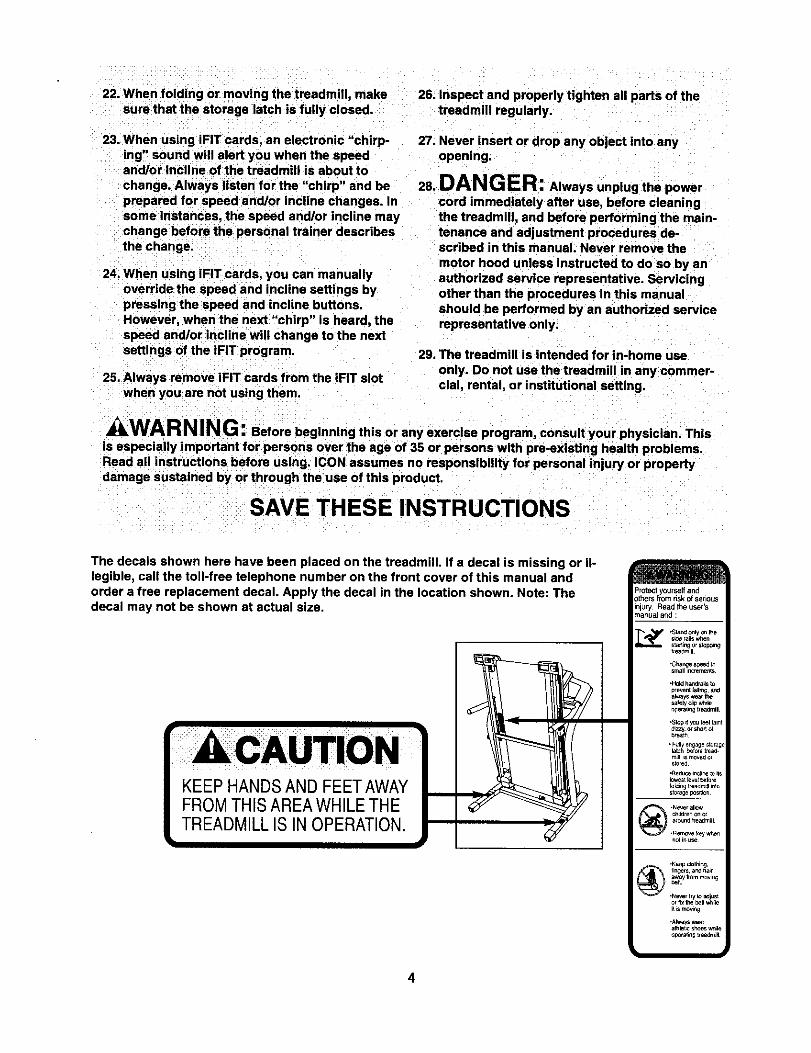
2. Insert the other Extension Leg (97) into the indi-cated bracket on the base of the Uprights (85) asshown.
Attach the Extension Leg (97) with two ExtensionLeg Bolts (87), two Star Washers (67), and twoExtension Leg Nuts (91) as shown. Firmlytighten the Extension Leg Bolts.
2
Bracket
97
3. Attach the four Base Pads (81) to the base of theUprights (85) in the indicated locations with four1" Tek Screws (82) and four Plastic Washers(101). Note: One replacement Base Pad may beincluded. Use the Base Pad to replace any BasePad that becomes worn.
With the help of a second person, carefully tipthe treadmill down so that the Base Pads (81)are resting on the floor and the Uprights (85) arein the vertical position.
101
101
82
101
4. Remove the band secunng the UprightWireHarness (73) to the right Upright (85). Have asecond person hold the console assembly nearthe right Upright.
Connect the Upright Wire Harness (73) to thewiresextending from the console assembly. Makesure to connect the connectors properly (seethe inset drawing). The connectors shouldslide together easily and snap into place. Ifthe connectorsdo not slide together easily andsnap into place, turn one connector and tryagain. IF THE CONNECTORS ARE NOT CON-NECTED PROPERLY, THE CONSOLE MAYBE DAMAGED WHEN THE POWER ISTURNED ON. insertthe connectorsintothe rightUpright(85),
4Console
Assembly--._.
73
.88
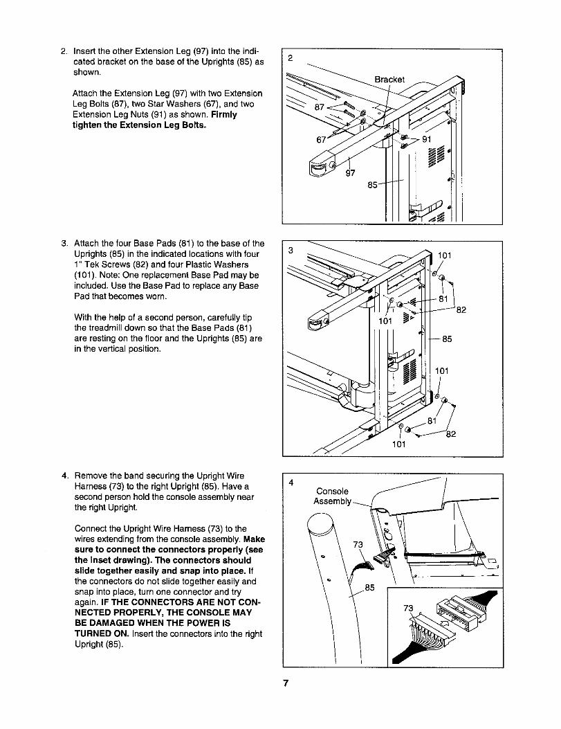
5. With the help of a second person, set the con-sole assembly on the Uprights (85). Make surethat no wires are pinched. Attach the consoleassembly with four Console Bolts (72) and fourStar Washers (67). Start all four Console Boltsbefore tightening any of them. i
=-72
r85
ConsoleAssembly
6. Press the Latch Insert (77) intothe right side ofthe left Upright (85), and press the Knob Insert(92) into the left side of the left Upright. Use arubber mallet, if necessary.
Remove the knob from the pin. Make sure thatthe collar and the spring are on the pin. Next, in-sert the pin into the Latch Insert, and tighten theknob back onto the pin.
Knol77
lng
Collar
7. Make sure that all parts are properly tightened before you use the treadmill. Keep the includedallenwrench in a secure place. The alien wrench is used to adjust the walkingbelt (see page 23). To protect thefloor or carpet from damage, place a mat under the treadmill.
If you purchase the optional chest pulse sensor (see page 19), follow the steps below to install the re-ceiver included with the chest pulse sensor,
1. Make sure that the power cord is unplugged.Remove the indicated Screw (7) and the AccessDoor (95) from the left side of the Console Base(98).
2. Connect the wire on the receiver (A) to the indi-cated wire extending from the Console Base(98). Hold the receiver so the small cylinder isoriented as shown and is facing the ConsoleBase. Attach the receiver to the plastic posts onthe Access Door (95) withthe two includedsmallscrews.
3. Make sure that no wires are pinched,Reattach the Access Door (95) with the Screw(7). Discardthe other wires includedwith the re-ceiver.
Wire
SmallScrews
Cylinder
8

OPERATION AND ADJUSTMENT
THE PRE-LUBRICATED WALKING BELT
Your treadmill features a walking belt coated with high-performance lubricant. IMPORTANT: Never apply sil-icone spray or other substances to the walkingbelt or the walking platform. Such substances willdeteriorate the walking belt and cause excessivewear.
HOW TO PLUG IN THE POWER CORD
DANGER: Improper connectionof the equipment-grounding conductor canresult in an increased risk of electric shock.Check with a qualified electrician or service-man if you are in doubt as to whether theproduct Is properly grounded, Do not modifythe plug provided with the product--if it willnot fit the outlet, have a proper outletinstalled by a qualified electrician.
Your treadmill, like any other type of sophisticatedelectronic equipment, can be seriously damaged bysudden voltage changes in your home's power.Voltage surges, spikes, and noise interference canresult from weather conditions or from other appliancesbeing turned on or off. To decrease the possibility ofyour treadmill being damaged, always use a surgesuppressor with your treadmill (see drawing I atthe right). To purchase a surge suppressor, seeyour local NordicTrack dealer or call the toll-freetelephone number on the front cover of this man-ual and order part number 146148, or see your localelectronics store.
Use only a single-outlet surge suppressor that isUL 1449 listed as a transient voltage surge sup-pressor (TVSS). The surge suppressor must have aUL suppressed voltage rating of 400 volts or lessand a minimum surge dissipation of 450 joules.The surge suppressor must be electrically rated for120 volts AC and 15 amps. There must be a moni-toring light on the surge suppressor to indicatewhether it is functioning properly. Failure to use aproperly functioning surge suppressor could resultin damage to the control system of the treadmill. Ifthe control system is damaged, the walking beltmay change speed, accelerate, or stop unexpect-edly, which may result in a fall and serious injury.
This product must be grounded. If it should malfunc-tion or break down, grounding providesa path of leastresistance for electric current to reduce the riskof elec-
tric shock. This product is equippedwith a cord havingan equipment-groundingconductor and a groundingplug. Plug the power cord into a surge suppressor,and plug the surge suppressor into an appropriateoutlet that is properly installed and grounded inaccordance with all local codes and ordinances.Important: The treadmill is not compatible withGFCI-equipped outlets.
This product is for use on a nominal 120-volt circuit,and has a grounding plug that looks like the plug illus-trated in drawing 1 below. A temporary adapter thatlooks like the adapter illustrated indrawing 2 may beused to connect the surge suppressor to a 2-polereceptacle as shown in drawing 2 if a properlygrounded outlet is not available.
_Grounded Outlet Box
I_ _..1 _ Surge Suppressor
! ilp llI% i VJ Grounding Pin
Grounded Outlet G_ounding Plug_"_
Grounded Outlet Box
Adapter
"QSurge _uppressor
Metal Screw
The temporary adapter should be used only until aproperly grounded outlet (drawing 1) can be installedby a qualified electrician.
The green-colored rigid ear, lug, or the like extendingfrom the adapter must be connected to a permanentground such as a properly grounded outlet box cover.Whenever the adapter is used it must be held in placeby a metal screw. Some 2-pole receptacle outlet boxcovers are not grounded. Contact a qualified elec-trician to determine if the outlet box cover isgrounded before using an adapter.
9

CONSOLE DIAGRAM
4
3
2
1
0
00000000000000000OOOO0000000000000O000000OO00000000000000000000000000000000000000000000000000000000000O00000000OO000000000000000000000000000000000000000
A
Note: If there is a thin sheet of plasticon the face of the console, remove it.
00000000000000000O000000000000OO0000000000000000000000000000000000000000000000000000000000000000000000O000000000000OO00O000000000OOOOO000000000000000000
Stop )
FEATURES OF THE CONSOLE
The treadmill console offers an impressive array offeatures designed to help you get the most from yourworkouts. When the manual mode of the console is se-lected, the speed and incline of the treadmill can bechanged with the touch of a button. As you exercise,the console will display continuous exercise feedback.You can even measure your heart rate using the built-in handgrip pulse sensor or the optional chest pulsesensor (see page 19).
In addition, the console features six preset programs.Each program automatically controls the speed and in-cline of the treadmill as it guides you through an effec-tive workout. You can even create your own customworkout programs and save them in memory for futureuse.
The console also features the new iFIT InteractiveWorkout system. The iFIT system enables the consoleto accept iFIT Interactive Workout Cards containing
workout programs designed to help you achieve spe-cific fitness goals. For example, lose unwanted poundswith the 8-week Weight Loss program, or train for along-distance run with the Marathon program, iFIT pro-grams automatically control the treadmill while thevoice of a personal trainer coaches you and motivatesyou through every step of your workout. One iFIT Cardwith three new programs is included. Additional iFITCards are available separately. To purchase iFITCards at any time, go to www.iFIT.com or call thetoll-free telephone number on the front cover ofthis manual, iFIT Cards are also available at selectstores.
To use the manual mode of the console, follow thesteps beginningon page 11. To use a presetprogram, see page 14. To create and use a customprogram, see pages 15 and 16. To use an iFIT card,see page 17.
Note: If there is a sheet of clear plastic on the console,peel off the clear plastic.
lO
HOW TO TURN ON THE POWER
Note: To prevent damage to the walking platform,always wear clean shoes while using the treadmill.
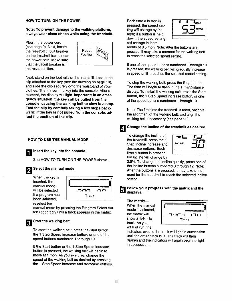
Plug in the power cord(see page 9). Next, locatethe reset/off circuit breakeron the treadmill frame nearthe power cord. Make surethat the circuit breaker is inthe reset position.
ResetPosition
Next, stand on the foot rails of the treadmill. Locate theclip attached to the key (see the drawing on page 10),and slide the clip securely onto the waistband of yourclothes. Then, insert the key into the console. After amoment, the display will light. Important: In an emer-gency situation, the key can be pulled from theconsole, causing the walking belt to slow to a stop.Test the clip by carefully taking a few steps back=ward; if the key is not pulled from the console, ad-just the position of the clip.
HOW TO USE THE MANUAL MODE
B Insert the key into the console.
See HOW TO TURN ON THE POWER above.
B Select the manual mode.
When the key is
inserted, the !--_t_mT r_a
manual modewill be selected, r"lt'lIf a program has ckbeen selected,reselect the
manual mode by pressing the Program Select but-ton repeatedly until a track appears in the matrix.
[_1 Start the walking belt.
To start the walking belt, press the Start button,the 1 Step Speed increase button,or one of thespeed buttonsnumbered 1 through 10.
If the Start button or the 1 Step Speed increasebutton is pressed, the walking belt will begin tomove at 1 mph. As you exercise, change thespeed of the walking belt as desired by pressingthe 1 Step Speed increase and decrease buttons.
B
Each time a button ispressed, the speed set-ting will change by 0.1mph; if a button is helddown, the speed settingwill change in incre-
I I
5.3°°
ments of 0.5 mph. Note: Afterthe buttons arepressed, it may take a moment for the walking beltto reach the selected speed setting.
If one of the speed buttons numbered 1 through 10is pressed, the walking belt will gradually increasein speed until it reaches the selected speed setting.
To stop the walking belt, press the Stop button.The time will begin to flash in the Time/Distancedisplay. To restart the walking belt, press the Startbutton, the 1 Step Speed increase button, or oneof the speed buttons numbered 1 through 10.
Note: The first time the treadmill is used, observethe alignment of the walking belt, and align thewalking belt if necessary (see page 23).
Change the incline of the treadmill as desired.
To change the incline ofthe treadmill, press the 1Step Incline increase anddecrease buttons. Eachtime a button is pressed,the incline will change by0.5%. To change the incline quickly, press one ofthe incline buttons numbered 0 through 12. Note:After the buttons are pressed, it may take a mo-ment for the treadmill to reach the selected inclinesetting.
Follow your progress with the matrix and thedisplays.
The matrix--When the manualmode is selected,the matrix willshow a 1/4-miletrack. As youwalk or run, theindicatorsaround the track will light in successionuntil the entire track is lit. The track will thendarken and the indicators will again begin to lightin succession.
11
The Training Zonesdisplay--This displayindicatesthe approxi-mate intensitylevel ofyour exercise. If five orsix indicatorsare lit,forexample, the displayshows that your pace isideal for aerobic exercise.
7rainfrlg Zones ]
.......==]........_=!
The Time/Distance dis-play--This display willshow the elapsed timeand the distancethat youhave walked or run dur-ingyour workout. Note:When a program is selected (except for a customprogram), the display will show the time remainingin the program instead of the elapsed time. Thedisplay will change from one number to the otherevery few seconds.
The Calories/Pulsedisplay--This displaywill show the approxi-mate number of caloriesyou have burned.Thedisplaywill also show
t-1
c;-3 your heart rate when you use the handgrip pulsesensor or the optionalchest pulse sensor.
The Carbs/Inciine dis-play--This display willshow the approximatenumber of grams ofcarbsyou have burnedand the inclinelevel of
the treadmill. Note: Each time the incline changes,the displaywill show the incline setting.
The Speed/Pace dis-play--This display willshow the speed of thewalkingbelt and yourpace (pace is measuredin minutes per mile). Thedisplay willchange from one number to the otherevery few seconds.
B
Note: The console can display speed and dis-tance in either miles or kilometers.To change theunit of measurement, see THE USER'S MODE onpage 18. Note: For simplicity, all instructions inthis section refer to miles.
To see the total numberof miles that the walkingbelt has moved since thelast reset, press theOdometer button; the totalnumber of miles will ap-
u mm
mm •
NO nunmm
pear inthe matrix. To reset this number, holddown the Odometer button for a few seconds.
The number will appear in the display for a fewseconds.
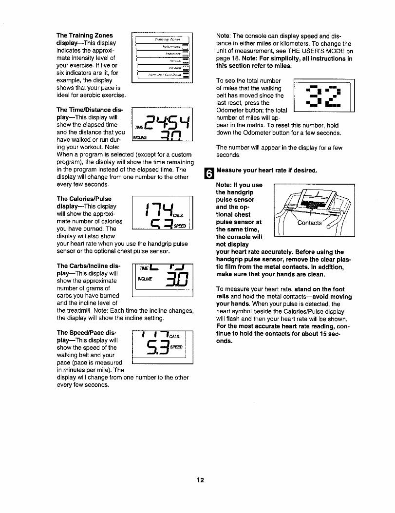
Measure your heart rate if desired.
Note: If you usethe handgrlppulse sensorand the op-tional chestpulse sensor atthe same time,the console willnot displayyour heart rate accurately. Before using thehandgrip pulse sensor, remove the clear plas-tic film from the metal contacts. In addition,make sure that your hands are clean.
To measure your heart rate, stand on the footrails and hold the metal contacts--avoid movingyour hands. When your pulse is detected, theheart symbol beside the Calories/Pulse displaywill flash and then your heart rate will be shown.For the most accurate heart rate reading, con-tinue to hold the contacts for about 15 sec-onds.
12

B Turnonthefanif desired.To turn on the fan at low speed, press the Fanbutton;the word "LOW" will appear inthe matrixfor a few seconds. To turn on the fan at highspeed, press the button a second time; the word"HIGH" will appear inthematrix.To select theauto mode, press thebuttonagain; the word"AUTO" will appear inthe matrix. When theauto mode is selected,the speed of the tan will automatically increaseand decrease as the speed of the walking belt in-creases and decreases.
QIIT!-IIBKs_=H-_- I
To turn off the fan, press the Fan button again, theword "OFF" will appear in the matrix. Note: If thefan is left on when the walking belt is stopped, thefan will automatically turn off after a few minutes.
r_ when you are finished exercising, remove thekey.
Step onto the foot rails, press the Stop button, andadjust the incline of the treadmill to the lowestsetting. The incline must be at the lowest settingwhen the treadmill is folded to the storage posi-tion or the treadmill will be damaged. Next, re-move the keyfromthe consoleand putit ina se-cureplace. Note: If the display remains lit afterthe key is removed, the console is in the"demo" mode. See page 18 and turn off thedemo mode.
When you are finished using the treadmill,switch the reset/oft circuit breaker to the "off"position and unplug the power cord.
13

HOW TO USE A PRESET PROGRAM
D Insert the key Into the console.
See HOW TO TURN ON THE POWER on page11.
B Select one of the preset programs.
To select one of the sixpreset programs, pressthe Program Select but-ton repeatedly until "P 1,""P 2," "P 3," "P 4," "P 5,"or "P 6" appears in theCalories/Pulse display.
"it"
As each preset program is selected, the maximumspeed setting of the program and the maximumincline setting of the program will flash in the dis-plays for a few seconds. The Time/Distance dis-play will showhow long theprogram will last.A profile of thespeed settings ofthe program will :3t-I,t--lt'l p_...3 LJ'L,/I,Jscroll across the ,'- ,"1 "_ t-matrix.
Press the Start button or the 1 Step Speed in-crease button to start the program.
A moment after the button is pressed, the tread-mill will automatically adjust to the first speed andincline settings for the program. Hold the handrailsand begin walking.
Each program is divided into 30, 50, or 60 one-minute segments. One speed setting and one in-cline setting are programmed for each segment.Note: The same speed setting and/or incline settingmay be programmed for two or more consecutivesegments.
The speed set-ting for the firstsegment will beshown in theflashing CurrentSegment columnof the matrix.
(The incline settingsare not shown in the matrix.)The speed settings for the following segments willbe shown in the columns to the right.
When only three seconds remain in the first seg-ment of the program, both the Current Segmentcolumn and the column to the right will flash and aseries of tones will sound. If the speed and/or theincline of the treadmill is about to change, thespeed setting and/or the incline setting will flash inthe displays to alert you.
When the first segment is completed, allspeedsettings willmove one column to the le_ Thespeed setting for the second segment will then beshown in the flashing Current Segment columnand the treadmill will automatically adjust to thespeed and incline settings for the second seg-ment. Note: If all seven indicators in the CurrentSegment column are lit, the speed settings maymove downwardso that only the highest indicatorsappear in the matrix.
The program will continue in this way until thespeed setting for the last segment is shown in theCurrent Segment column and the last segmentends. The walking belt will then slow to a stop.
If the speed or incline setting for the currentsegment is too high or too low, you can manuallyoverride the setting by pressing the Speed orIncline buttons. Every few times a Speed button ispressed, an additional indicator will light or darkenin the Current Segment column; If any of thecolumns to the right of the Current Segment col-umn have the same number of lit indicators as theCurrent Segment column, an additional indicatormay light or darken in those columns as well.Important: When the current segment of theprogram ends, the treadmill will automaticallyadjust to the speed and incline settings for thenext segment.
To stop the program at any time, press the Stopbutton. The time will begin to flash in theTime/Distance display. To restart the program,press the Start button or the 1 Step Speed in-crease button. The walking belt will begin to moveat I mph. When the next segment of the programbegins, the treadmill will automatically adjust to thespeed and incline settings for the next segment.
14
B Follow your progress with the displays.
See step 5 on page 11.
_J_ Measure your heart rate if desired.
See step 6 on page 12.
r_Turn on the fan if desired.
See step 7 on page 13.
B When you are finished exercising, remove thekey from the console.
When the program ends, make sure that the in-cline of the treadmill is at the lowest setting.Next, removethe key from the console and put it ina safe place. Note: If the display remains litafter the key is removed, the console is in the"demo" mode. See page 18 and turn off thedemo mode.
When you are finished using the treadmill,switch the reset/off circuit breaker to the "off"position and unplug the power cord.
HOW TO CREATE A CUSTOM PROGRAM
B Insert the key into the console.
See HOW TO TURN ON THE POWER on page11.
B Select one of the custom programs.
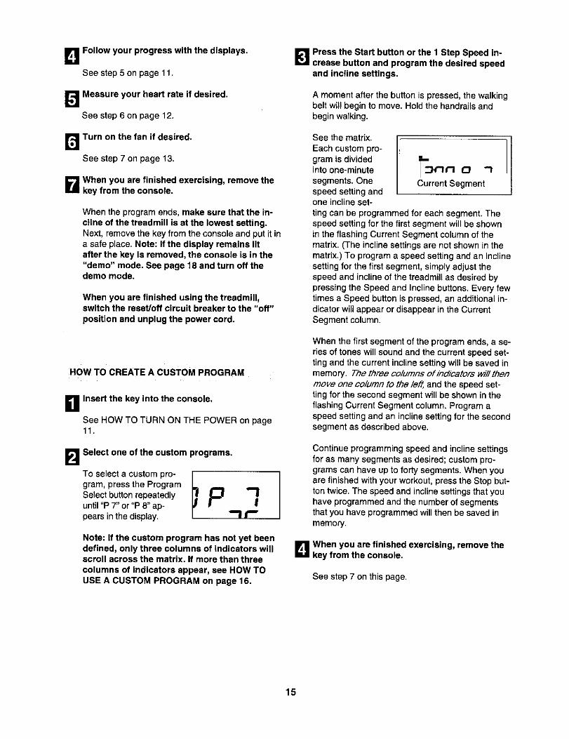
To select a custom pro-gram, press the ProgramSelect button repeatedlyuntil "P 7" or "P 8" ap-pears in the display. --It'-
Note: If the custom program has not yet beendefined, only three columns of indicators willscroll across the matrix. If more than threecolumns of indicators appear, see HOW TOUSE A CUSTOM PROGRAM on page 16.
[]Press the Start button or the 1 Step Speed in-crease button and program the desired speedand incline settings.
A moment after the button is pressed, the walkingbelt will begin to move. Hold the handrails andbegin walking.
See the matrix.Each custom pro-gram is dividedinto one-minute _,t"lrl 0 -Isegments. One Current Segmentspeed settingandone inclineset-ting can be programmed for each segment. Thespeed setting for the first segment will be shownin the flashing Current Segment columnof thematrix. (The incline settingsare not shown inthematrix.) To programa speed setting and an inclinesetting for the first segment, simplyadjust thespeed and inclineof the treadmill as desired bypressing the Speed and Incline buttons. Every fewtimes a Speed buttonis pressed, an additional in-dicatorwill appear or disappear in the CurrentSegment column.
When the first segment of the program ends, a se-ries of tones will sound and the current speed set-ting and the current incline setting will be saved inmemory. The three columns of indicators will thenmove one column to the le_ and the speed set-ting for the second segment will be shown in theflashing Current Segment column. Program aspeed setting and an incline setting for the secondsegment as described above.
Continue programming speed and incline settingsfor as many segments as desired; custom pro-grams can have up to forty segments. When youare finished with your workout, press the Stop but-ton twice. The speed and inclinesettings that youhave programmed and the number of segmentsthat you have programmed will then be saved inmemory.
B When you are finished exercising, remove thekey from the console.
See step 7 on this page.
15
HOWTO USE A CUSTOM PROGRAM
D Insert the key into the console.
See HOW TO TURN ON THE POWER on page11.
B Selectone of the custom programs.
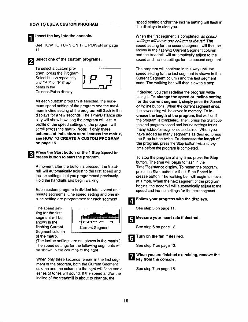
To select a custom pro-gram, press the ProgramSelect button repeatedlyuntil "P 7" or "P 8" ap-pears in theCalories/Pulse display.
As each custom program is selected, the maxi-mum speed setting of the program and the maxi-mum incline setting of the program will flash in thedisplays for a few seconds. The Time/Distance dis-play will show how long the program will last. Aprofile of the speed settings of the program willscroll across the matrix. Note: If only threecolumns of indicators scroll across the matrix,see HOW TO CREATE A CUSTOM PROGRAMon page 15.
_'1 Press the Start button or the I Step Speed In-crease button to start the program.
A moment after the button is pressed, the tread-mill will automatically adjust to the first speed andincline settings that you programmed previously.Hold the handrails and begin walking.
Each custom program is divided into several one-minute segments. One speed setting and one in-cline setting are programmed for each segment.
The speed set-ting for the firstsegment will beshown in theflashing CurrentSegment columnof the matrix.
t'l t-I '-I
Current Segment
(The incline settings are not shown in the matrix.)The speed settings for the following segments willbe shown in the columns to the right.
When only three seconds remain inthe first seg-ment of the program, both the Current Segmentcolumn and the column to the right will flash and aseries of tones will sound. If the speed and/or theincline of the treadmill is about to change, the
speed settingand/or the inclinesetting will flash inthe displays to alert you.
When the first segment is completed, al/speedsettings will move one co/umn to the led Thespeed setting for the second segment will then beshown in the flashing Current Segment columnand the treadmill will automatically adjust to thespeed and incline settings for the second segment.
The program will continue in this way until thespeed setting for the last segment is shown in theCurrent Segment column and the last segmentends. The walking belt will then slow to a stop.
If desired, you can redefine the program whileusing it. To change the speed or incline settingfor the current segment, simplypressthe Speedor Inclinebuttons.When the currentsegmentends,the new settingwillbe saved in memory. To in-crease the length of the program, first wait untilthe programis completed.Then, pressthe Startbut-ton and programspeedand inclinesettingsfor asmany additionalsegmentsas desired.When youhave added as many segments as desired, pressthe Stop buttontwice. To decrease the length ofthe program, pressthe Stopbuttontwiceat anytime beforethe programis completed.
To stop the program at any time, press the Stopbutton. The time will begin to flash in theTime/Resistance display. To restart the program,press the Start button or the 1 Step Speed in-crease button. The walking belt will begin to moveat 1 mph. When the next segment of the programbegins, the treadmill will automatically adjust to thespeed and incline settings for the next segment.
B Follow your progress with the displays.
See step 5 on page 11.
[]Measure your heart rate if desired.
See step 6 on page 12.
r_ Turn on the fan if desired.
See step 7 on page 13.
B When you are finished exercising, remove thekey from the console.
See step 7 on page 15.
16
HOW TO USE AN IFIT CARD
L1Insert the key into the console.
See HOW TO TURN ON THE POWER on page11.
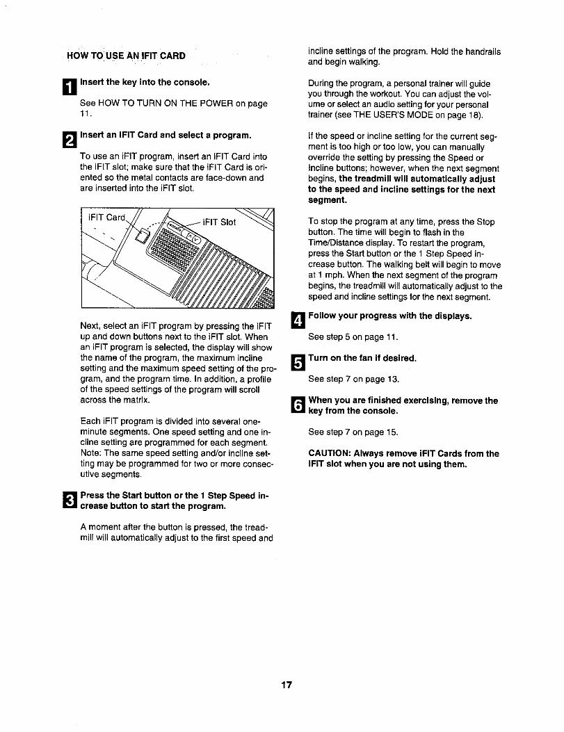
Insert an iFIT Card and select a program.
To use an iFIT program, insert an iFIT Card intothe iFIT slot;make sure that the iFIT Card is ori-ented so the metal contactsare face-down andare inserted into the iFIT slot.
iFIT Card\
Next, select an iFIT program by pressing the iFITup and down buttons next to the iFIT slot. Whenan iFIT program is selected, the display will showthe name of the program, the maximum inclinesetting and the maximum speed setting of the pro-gram, and the program time. In addition, a profileof the speed settings of the program will scrollacross the matrix.
Each iFIT program is divided into several one-minute segments. One speed setting and one in-cline setting are programmed for each segment.Note: The same speed setting and/or incline set-ting may be programmed for two or more consec-utive segments.
B Press the Start button or the 1 Step Speed in-crease button to start the program.
A moment after the button is pressed, the tread-mill will automatically adjust to the first speed and
incline settings of the program. Hold the handrailsand begin walking.
During the program, a personal trainer will guideyou through the workout. You can adjust the vol-ume or select an audio setting for your personaltrainer (see THE USER'S MODE on page 18).
if the speed or incline setting for the current seg-ment is too high or too low, you can manuallyoverride the setting by pressing the Speed orIncline buttons; however, when the next segmentbegins, the treadmill will automatically adjustto the speed and incline settings for the nextsegment.
To stop the program at any time, press the Stopbutton. The time will begin to flash in theTime/Distance display. To restart the program,press the Start button or the 1 Step Speed in-crease button. The walking belt will begin to moveat 1 mph. When the next segment of the programbegins, the treadmill will automatically adjust to thespeed and incline settings for the next segment.
B Follow your progress with the displays.
See step 5 on page 11.
B Turn on the fan if desired.
See step 7 on page 13.
B When you are finished exercising, remove thekey from the console.
See step 7 on page 15.
CAUTION: Always remove iFIT Cards from theiFIT slot when you are not using them.
17
THE USER'S MODE
The console features a user's mode that keeps track ofthe total number of miles that the walking belt hasmoved and the total number of hours that the treadmillhas been operated. The user's mode also allows youto select miles or kilometers as the unit of measure-ment and to turn on and turn off the demo mode.
When the user's mode is selected, you can alsochoose an audio setting and a volume setting for youriFIT workouts.
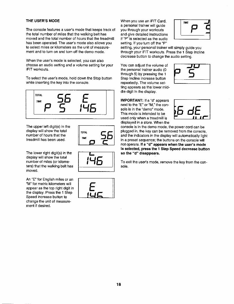
To setect the user's mode, hold down the Stop buttonwhile inserting the key into the console.
The upper left digit(s) in thedisplay will show the totalnumber of hours that thetreadmill has been used.
The lower right digit(s) in thedisplay will show the totalnumber of miles (or kilome-ters) that the walking belt hasmoved.
An "E" for English miles or an"M" for metric kilometers willappear as the top right digit inthe display. Press the 1 StepSpeed increase button tochange the unit of measure-ment if desired.
When you use an iFIT Card,a personal trainer will guideyou through your workoutsand give detailed instructionsif "P" is selected as the audiosetting. If you turn off the "P"setting, your personal trainer will simply guide youthrough your iF[T workouts. Press the 1 Step Inclinedecrease button to change the audio setting.
You can adjust the volume ofthe personal trainer audio (0through 5) by pressing the 1Step Inc_ineincrease buttonrepeatedly. The volume set-ting appears as the lower mid-die digit in the display.
IMPORTANT: If a "d" appearsnextto the "E" or "M," the con-sole is in the "demo" mode.This mode is intended to beused only when a treadmitt isdisplayed in a store. When theconsole is in the demo mode, the power cord can beplugged in, the key can be removed from the console,and the indicators in the display will automatically lightin a preset sequence; the buttons on the console willnot operate. If a "d" appears when the user's modeis selected, press the I Step Speed decrease button$o the "d" disappears.
To exit the user's mode, remove the key from the con-sole.
1B

THE OPTIONALCHESTPULSESENSOR
An optional chest pulse sensor offers hands-free oper-ation as it monitors your heart rate during your work-outs. To purchase the optional chest pulse sensor,call the toll-free telephone number on the frontcover of this manual.
HOW TO ADJUST THE CUSHIONING SYSTEM
The treadmill features a cushioning system that re-duces the impact as you walk or run on the treadmill.To increase the firmness of the walking platform, stepoff the treadmill and slide the cushion adjustors towardthe front of the treadmill. To decrease the firmness,slide the cushion adjustors toward the back of thetreadmill. Note: It may be helpful to lift on the plat-form as you slide the adjustors. Make sure thatboth adjustors are set at the same firmness level.The faster you run on the treadmill, or the more youweigh, the firmer the walking platform should be.
CushionAdjustor
Decrease CushionAdjustor
Platform
19
HOW TO FOLD AND MOVE THE TREADMILL
HOW TO FOLD THE TREADMILL FOR STORAGE
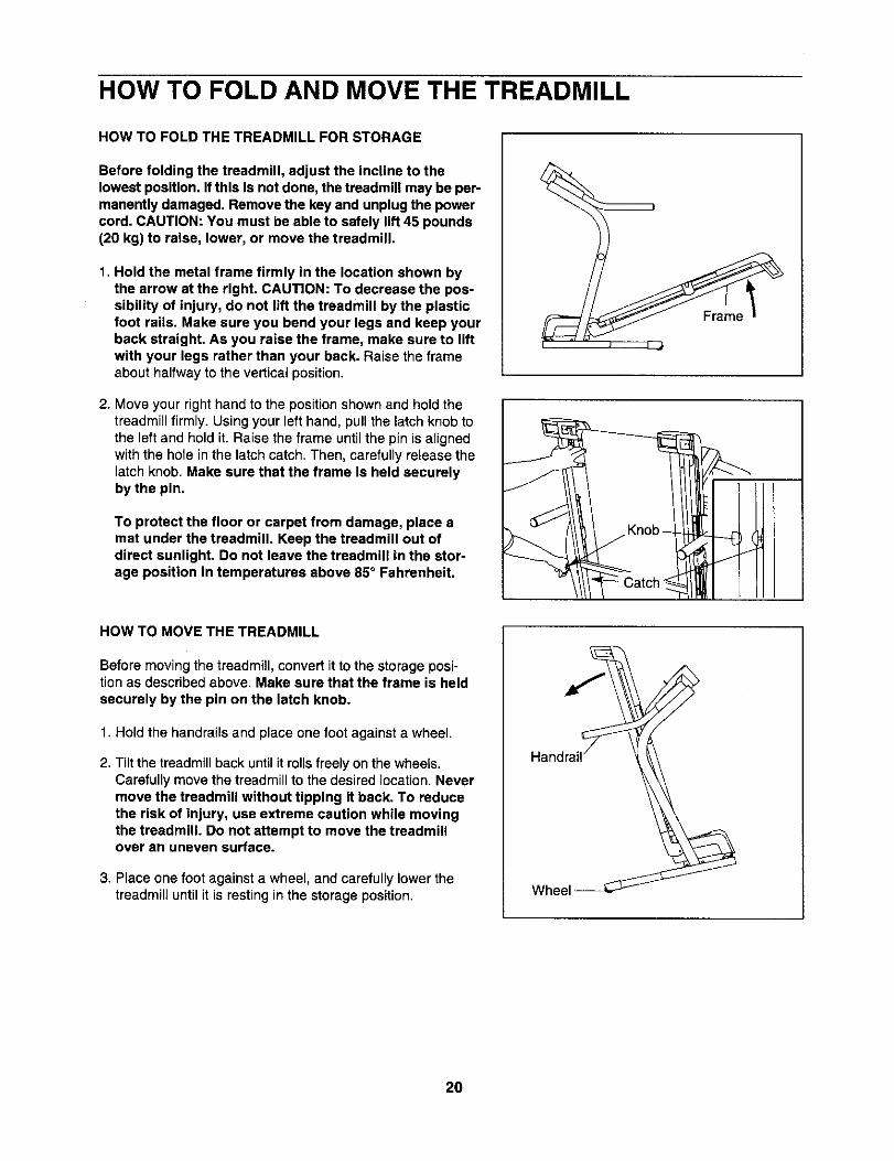
Before folding the treadmill, adjust the incline to thelowest position. If this is not done, the treadmill may be per-manently damaged. Remove the key and unplug the powercord. CAUTION: You must be able to safely lift 45 pounds(20 kg) to raise, lower, or move the treadmill.
1. Hold the metal frame firmly in the location shown bythe arrow at the right. CAUTION: To decrease the pos-sibility of injury, do not lift the treadmill by the plasticfoot rails. Make sure you bend your legs and keep yourback straight. As you raise the frame, make sure to liftwith your legs rather than your back. Raise the frameabout halfway to the vertical position.
2. Move your right hand to the position shown and hold thetreadmill firmly. Using your left hand, pull the latch knob tothe left and hold it. Raise the frame until the pin is alignedwith the hole in the latch catch. Then, carefully release thelatch knob. Make sure that the frame is held securelyby the pin.
To protect the floor or carpet from damage, place amat under the treadmill. Keep the treadmill out ofdirect sunlight. Do not leave the treadmill in the stor-age position in temperatures above 85° Fahrenheit.
HOW TO MOVE THE TREADMILL
Before moving the treadmill, convert it to the storage posi-tion as described above. Make sure that the frame is heldsecurely by the pin on the latch knob.
1. Hold the handrails and place one foot against a wheel.
2. Tilt the treadmill back until it rolls freely on the wheels.Carefully move the treadmill to the desired location.Nevermove the treadmill without tipping it back. To reducethe risk of injury, use extreme caution while movingthe treadmill. Do not attempt to move the treadmillover an uneven surface.
3. Place one foot against a wheel, and carefully lower thetreadmill until it is resting in the storage position. Wheel
20

HOW TO LOWER THE TREADMILL FOR USE
1. Hold the upper end of the treadmillwith your right hand asshown. Using your left hand, pull the latch knob to the leftand hold it. Pivot the frame down until it is past the pin onthe latch knob.
f
2. Hold the metal frame firmly with both hands, and lowerit to the floor. CAUTION: To decrease the possibility ofinjury, do not lower the frame by gripping only theplastic foot rails. Do not drop the frame to the floor.Make sure to bend your legs and keep your backstraight.
21
TROUBLESHOOTING
Most treadmill problems can be solved by following the steps below. Find the symptom that applies, andfollow the steps listed. If further assistance is needed, please see the front cover of this manual.
PROBLEM: The power does not turn on
SOLUTION: a, Make sure that the power cord is plugged into a surge suppressor, and that the surge suppressoris plugged into a properly grounded outlet (see page 9). Use onlya single-outlet surge suppressorthat meets allof the specificationsdescribed on page 9. Important: The treadmill is not compatiblewith GFCI-equipped outlets.
b. After the power cord has been plugged in, make sure that the key is inserted intothe console.
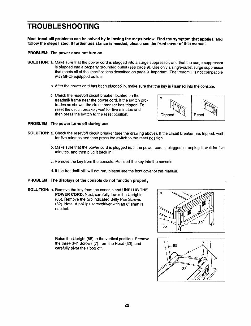
c. Check the reset/off circuit breaker located on thetreadmill frame near the power cord. If the switch pro-trudes as shown, the circuit breaker has tripped. Toreset the circuit breaker, wait for five minutes andthen press the switch to the reset position.
c
Tdpped_ Oe°et PROBLEM: The power turns off during use
SOLUTION: a. Check the reset/off circuit breaker (see the drawing above). If the circuit breaker has tripped, waitfor five minutes and then press the switchto the reset position.
b. Make sure that the power cord is plugged in. If the power cord is plugged in, unplug it, wait for fiveminutes, and then plug it back in.
c. Remove the key from the console. Reinsert the key into the console.
d. If the treadmill still will not run, please see the front cover of this manual.
PROBLEM: The displays of the console do not function properly
SOLUTION: a. Remove the key from the console and UNPLUG THEPOWER CORD. Next, carefully lower the Uprights(85). Remove the two indicated Belly Pan Screws(32). Note: A phillipsscrewdriver withan 8" shaft isneeded.
Raise the Upright (85) to the vertical position. Removethe three 3/4" Screws (7) from the Hood (33), andcarefully pivot the Hood off.
33
7
22
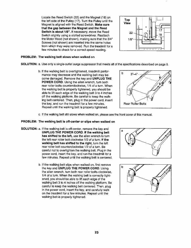
Locate the Reed Switch (22) and the Magnet (18) onthe left side of the Pulley (17). Turn the Pulley until theMagnet is aligned with the Reed Switch. Make surethat the gap between the Magnet and the ReedSwitch is about 1/8", If necessary, move the ReedSwitch slightly using a slotted screwdriver. Reattachthe Motor Hood (not shown), making sure that the 3/4"Screws (not shown) are inserted into the same holesfrom which they were removed. Run the treadmill for afew minutes to check for a correct speed reading.
TopView
22_
1/8"_
i i i d E i ii
PROBLEM: The walking belt slows when walked on
SOLUTION: a. Use only a single-outlet surge suppressor that meets all of the specifications described on page 9.
b. If the walking belt is overtightened, treadmill perfor-mance may decrease and the walking belt may be-come damaged. Remove the key and UNPLUG THEPOWER CORD. Using the allen wrench, turn bothrear roller bolts counterclockwise, 1/4 of a turn. Whenthe walking belt is properly tightened, you should beable to lift each edge of the walking belt 3 to 4 inchesoff the walking platform. Be careful to keep the walk-ing belt centered. Then, plug in the power cord, insertthe key, and run the treadmill for a few minutes.Repeat until the walking belt is properly tightened.
Rear Roller Bolts
c. If the walkingbelt still slows whenwalked on, please see the front cover of this manual.
PROBLEM: The walking belt is off-center or slips when walked on
SOLUTION: a. If the walking belt is oft-center, remove the key andUNPLUG THE POWER CORD. If the walking belthas shifted to the left, use the allen wrench to turnthe left rear roller bolt clockwise 1/2 of a turn; if thewalking belt has shifted to the right, turn the leftrear roller bolt counterclockwise 1/2 of a turn. Becareful not to overtighten the walking belt. Plug in thepower cord, insert the key, and run the treadmill for afew minutes. Repeat until the walking belt is centered.
a
b. if the walking belt slips when walked on, first removethe key and UNPLUG THE POWER CORD. Usingthe allen wrench, turn both rear roller bolts clockwise,1/4 of a turn. When the walking belt is correctly tight-ened, you should be able to lift each edge of thewalking belt 3 to 4 inches off the walking platform. Becareful to keep the walking belt centered. Then, plugin the power cord, insert the key, and carefully walkon the treadmill for a few minutes. Repeat until thewalking belt is properly tightened.
b
23

PROBLEM: The incline of the treadmill does not change correctly
SOLUTION: a. With the key in the console, press one of the Incline buttons. While the incline is changing, re-move the key. After a few seconds, re-insert the key. The treadmill will automatically riseto themaximum inclinelevel and then returnto the minimumlevel. This will recalibratethe inclinesys-tem.
24
CONDITIONING GUIDELINES
WARNING: Before beginning this
or any exercise program, consult your physi-cian. This is especially important for individu-als over the age of 35 or individuals with pre-existing health problems.
The pulse sensor is not a medical device.Various factors, including your movement,may affect the accuracy of heart rate readings.The sensor is intended only as an exercise aidin determining heart rate trends in general.
The following guidelines will help you to plan your ex-ercise program. For more detailed exercise informa-tion, obtain a reputable book or consult your physician.
EXERCISE INTENSITY
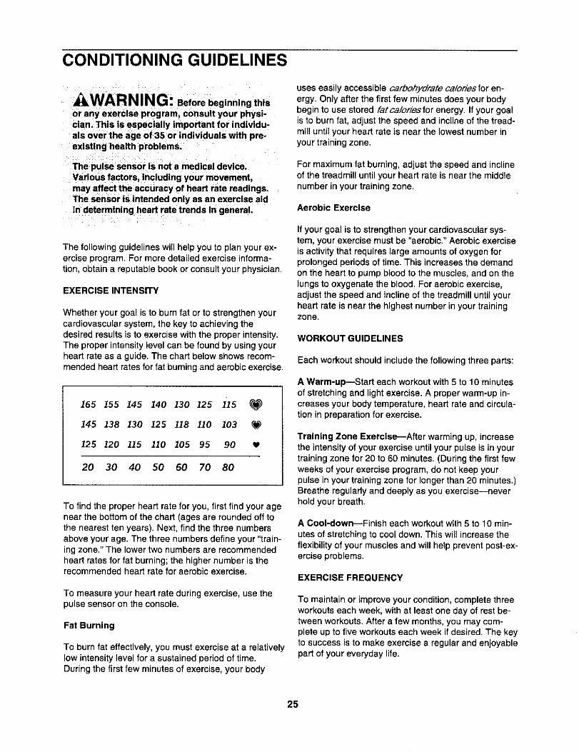
Whether your goal is to burn fat or to strengthen yourcardiovascular system, the key to achieving thedesired results is to exercise with the proper intensity.The proper intensity level can be found by usingyourheart rate as a guide. The chart below shows recom-mended heart rates for fat burning and aerobic exercise.
165 155 145 140 130 125 1i5 P_
145 138 130 125 118 110 103 _,_)
125 120 115 110 105 95 90
20 30 40 50 60 70 80
To find the proper heart rate for you, first find your agenear the bottom of the chart (ages are rounded off tothe nearest ten years). Next, find the three numbersabove your age. The three numbers define your "train-ing zone." The lower two numbers are recommendedheart rates for fat burning; the higher number is therecommended heart rate for aerobic exercise.
To measure your heart rate during exercise, use thepulse sensor on the console.
Fat Burning
To burn fat effectively, you must exercise at a relativelylow intensity level for a sustained period of time.During the first few minutes of exercise, your body
uses easily accessible carbohydrate ca/ories for en-ergy. Only after the first few minutes does your bodybegin to use stored fatca/or/esfor energy. If your goalis to burn fat, adjust the speed and incline of the tread-mill until your heart rate is near the lowest number inyour training zone.
For maximum fat burning, adjust the speed and inclineof the treadmill until your heart rate is near the middlenumber in your training zone.
Aerobic Exercise
If your goal is to strengthen your cardiovascular sys-tem, your exercise must be "aerobic." Aerobic exerciseis activity that requires large amounts of oxygen forprolonged periods of time. This increases the demandon the heart to pump blood to the muscles, and on thelungs to oxygenate the blood. For aerobic exercise,adjust the speed and incline of the treadmill until yourheart rate is near the highest number in your trainingzone.
WORKOUT GUIDELINES
Each workout should include the following three parts:
A Warm-up--Start each workout with 5 to 10 minutesof stretching and light exercise. A proper warm-up in-creases your body temperature, heart rate and circula-tion in preparation for exercise.
Training Zone Exercise_After warming up, increasethe intensity of your exercise until your pulse is in yourtraining zone for 20 to 60 minutes. (During the first fewweeks of your exercise program, do not keep yourpulse in your training zone for longer than 20 minutes.)Breathe regularly and deeply as you exercise--neverhold your breath.
A Cool-down--Finish each workout with 5 to 10 min-utes of stretchingto cool down. This will increase theflexibility of your muscles and will help prevent post-ex-ercise problems.
EXERCISE FREQUENCY
To maintain or improve your condition, complete threeworkouts each week, with at least one day of rest be-tween workouts. After a few months, you may com-plete up to five workouts each week if desired. The keyto success is to make exercise a regular and enjoyablepart of your everyday life.
25

PART LISTmModel NO. NTL07806.2 R0800A
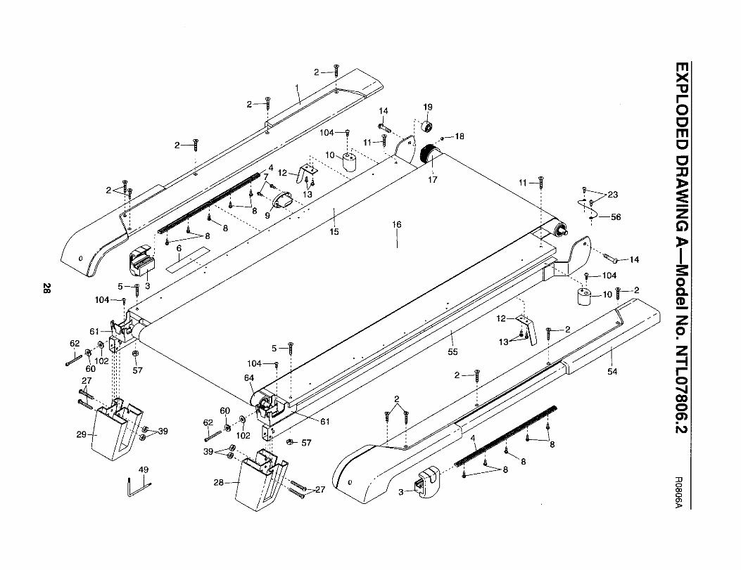
To locate the parts listed below, see the EXPLODED DRAWING starting on page 28.
KeyNo. Qty. Description Key No. Qty. Description
1 1 Left Foot Rail 52 102 10 Foot Rail Screw 53 13 2 Cushion Adjustor 54 14 2 Adjustor Guide 55 15 2 Rear Platform Screw 56 16 1 Latch Warning Decal 57 27 17 3/4" Screw 58 18 10 Adjustor Guide Screw 59 19 1 Latch Catch 60 210 2 Isolator 61 211 2 Platform Screw, Front 62 212 2 Belt Guide 63 213 4 Belt Guide Screw 64 114 2 Frame Pivot Bolt 65 115 1 Walking Platform 66 116 1 Walking Belt 67 817 1 Front Roller 68 118 1 Magnet 69 119 2 Frame Spacer 70 120 3 Nut 71 221 1 Reed Switch Clip 72 422 1 Reed Switch 73 123 10 1/2" Screw 74 124 2 Cable Tie 75 125 1 Drive Motor 76 126 1 Motor Belt 77 127 4 Rear Foot Bolt 78 228 1 Right Rear Foot 79 229 1 Left Rear Foot 80 230 2 Lift Frame Nut 81 631 2 Motor Bolt 82 432 6 Belly Pan Screw 83 433 1 Motor Hood 84 234 3 Hood Clip 85 135 1 Grommet 86 136 1 Upper Clevis Pin 87 437 2 Cotter Pin 88 238 1 Front Roller Adjustment Bolt 89 239 4 Rear Foot Nut 90 240 1 Incline Motor 91 441 1 Incline Motor Pin, Lower 92 142 1 Transformer 93 143 1 Controller 94 144 1 Reset/Off Circuit Breaker 95 145 1 Belly Pan 96 146 2 Wheel Housing Screw 97 247 1 Power Cord 98 148 1 Incline Wire Harness 99 1249 1 Allen Wrench 100 150 1 Tie Holder 101 651 1 Releasable Tie 102 2
PlasticTieFront Roller BushingRight Foot RailFrameFront Roller Ground WirePlatform NutIdler WasherIdler PulleyRear Roller Lock WasherRear Roller BracketRear Roller BoltWheel PinRear RollerFilter WireIdler Pulley BoltStar WasherIdler Arm BoltIdler Arm SpacerHandrailRound Upright EndcapConsole BoltUpright Wire HarnessIdler ArmIdler Arm SpringLatch AssemblyLatch InsertHandrail EndcapSquare Upright EndcapLift Frame Pivot BoltBase Pad1" Tek ScrewU-nutCaution DecalUprightBook HolderExtension Leg BoltWheel HousingFront WheelConsole Fan ScrewExtension Leg NutKnob InsertiFIT WireLift FrameAccess DoorLift Frame Ground WireExtension LegConsole BaseScrewConsole Fan AssemblyPlastic WasherRear Roller Washer
26
KeyNo. Qty. Description
103 1 Key/Clip104 4 Isolator Screw/Bracket Screw105 1 Console106 1 iFIT Wire
# 1 12" Blue Wire, 2F# 1 8" Blue Wire, M!F
Key No. Qty. Description
# 1 8" Green Wire, F/Ring# 1 4" Red Wire, M/F# 1 User's Manual
#These parts are not illustrated.Specifications are subject to change without notice.
ORDERING REPLACEMENT PARTS
To order replacement parts, see the front cover of this manual. When ordering parts, please be prepared to givethe following information:
• the MODEL NUMBER OF THE PRODUCT (NTL07806.2)
• the NAME OF THE PRODUCT (NordicTrack C2255 treadmill)
• the SERIAL NUMBER OF THE PRODUCT (see the front cover of this manual)
• the KEY NUMBER AND DESCRIPTION OF THE PART(S) (see the PART LIST starting on page 26 and theEXPLODED DRAWING starting on page 28)
27
104_
15
62
49
6O
14 19
=
16
2
17 ,,4
55
54
o(30oco
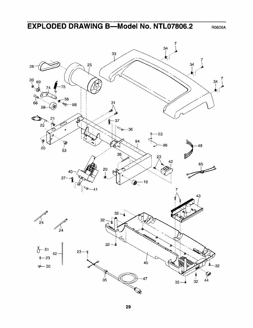
EXPLODED DRAWING B--Model No. NTL07806.2 RO806A
25
33
734
ao53
24
52
_23-_'-- 50
31
94
23
42
29
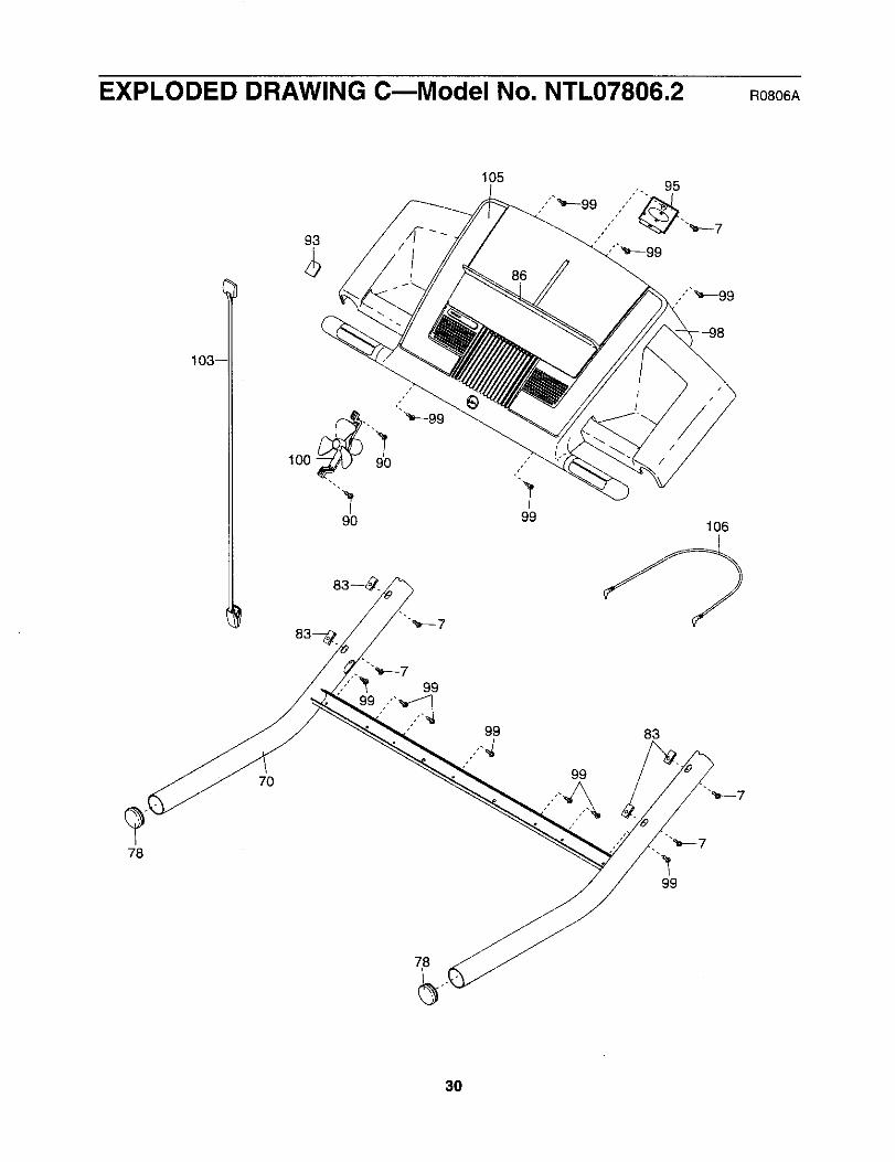
EXPLODED DRAWING C--Model No. NTL07806.2 RO806A
93
105
103-
100
9O
99
99106
78
7O
99
99
83
78
30

EXPLODED DRAWING DmModel No. NTL07806.2 Roso6A
"_C/67 "_72
'_ 72 73 71
92 72
.._. 67
_72
76 7
79,-30
88
i
106
88
101_
81-q_
82_
85
84
73
97
ii
,106
3O
%
_:_-- 101i
_r--82
8O
79
_101
_--81
4_--82
7
8963 ,I),_46
63_:" _81
_--4631

LIMITED WARRANTY
WHAT IS COVERED--The entire NordicTraak C2255 treadmill ("Product") is warranted to be free of alldefects in mate-rial and workmanship.
WHO IS COVERED--The odginal purchaser or any person receiving the Product as a gift from the original purchaser.
HOW LONG IS IT COVERED--ICON Health & Fitness, inc. ("ICON"), warrants the drive motor for life. Parts and laborare warranted for one year from the date of purchase.
WHAT WE DO TO CORRECT COVERED DEFECTS--We will ship to you, without charge, any replacement part orcomponent, providing the repairs are authodzed by ICON first and are performed by an ICON trained and authorizedservice provider, or, at our option, we will replace the Product.
WHAT IS NOT COVERED---Any failures or damage caused by unauthodzed service, misuse, accident, negligence, im-proper assembly or installation, alterations, modifications without our written authorization or by failure on your part touse, operate, and maintain as set out in your User's Manual ("Manual"). This warranty does not extend to products usedfor commercial or rental purposes.
WHAT YOU MUST DO--Always retain proof of purchase, such as your bill of sale; store, operate, and maintain theProduct as specified in the Manual; notify our Customer Service Department of any defect within 10 days after discov-ery of the defect; as instructed, return any defected part for replacement or, if necessary, the entire product, for repair.
USER'S MANUAL--It is VERY IMPORTANT THAT YOU READ THE MANUAL before operating the Product.Remember to do the periodic maintenance requirements specified in the Manual to assure proper operation and yourcontinued satisfaction.
HOW TO GET PARTS AND SERVICE--Simply call our Customer Service Department at 1-888-825-2588 and tell them
your name and address and the serial number of your Product. They will tell you how to get a part replaced, or if neces-sary, arrange for service where your Product is located or advise you how to ship the Product for service. Before ship-ping, always obtain a Hetum Authorization Number (RA No.) from our Customer Service Department; securely packyour Product (save the original shipping carton if possible); put the RA No. on the outside of the carton and insure the
product. Include a letter explaining the product or problem and a copy of your proof of purchase if you believe the ser-vice is covered by warranty.
ICON is not responsible or liable for indirect, special or consequential damages adsing out of or in connection with theuse or performance of the product or damages with respect to any economic loss, loss of property, loss of revenues or
profits, loss of enjoyment or use, costs of removal, installation or other consequential damages of whatsoever nature.Some states do not allow the exclusion or limitation of incidental or consequential damages. Accordingly, the above lim-itation may not apply to you.
The warranty extended hereunder is in lieu of any and all other warranties and any implied warranties of merchantabilityor fitness for a particular purpose is limited in its scope and duration to the terms set forth herein. Some states do not
allow limitations on how long an implied warranty lasts. Accordingly, the above limitation may not apply to you.
No one is authorized to change, modify or extend the terms of this limited warranty.
This warranty gives you specific legal rights and you may have other dghts which vary from state to state.
ICON HEALTH & FITNESS, INC., 1500 S. 1000 W., LOGAN, UT 84321-9813
Part No. 242790 R0806A Printed in USA © 2006 ICON IP, Inc.