MODEL NAME WATER PUMP AND MOTOR ASSEMBLYguest/... · MODEL NAME WATER PUMP AND MOTOR ASSEMBLY...
16
WATER PUMP AND MOTOR ASSEMBLY INSTALLATION MANUAL Publication Number: 620408124OPR Revision Date: April 02, 2014 Revision: D Visit the Cornelius web site at www.cornelius.com for all your Literature needs.
Transcript of MODEL NAME WATER PUMP AND MOTOR ASSEMBLYguest/... · MODEL NAME WATER PUMP AND MOTOR ASSEMBLY...
MODEL NAME
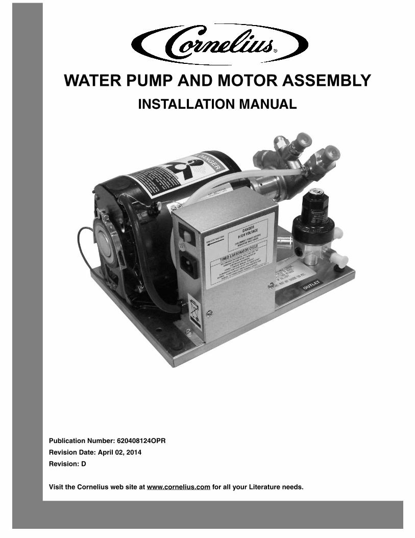
WATER PUMP AND MOTOR ASSEMBLYINSTALLATION MANUAL
Publication Number: 620408124OPR
Revision Date: April 02, 2014
Revision: D
Visit the Cornelius web site at www.cornelius.com for all your Literature needs.

The products, technical information, and instructions contained in this manual are subject to change without notice.
These instructions are not intended to cover all details or variations of the equipment, nor to provide for every possible
contingency in the installation, operation or maintenance of this equipment. This manual assumes that the person(s)
working on the equipment have been trained and are skilled in working with electrical, plumbing, pneumatic, and
mechanical equipment. It is assumed that appropriate safety precautions are taken and that all local safety and con-
struction requirements are being met, in addition to the information contained in this manual.
This Product is warranted only as provided in Cornelius’ Commercial Warrant applicable to this Product and is subject
to all of the restrictions and limitations contained in the Commercial Warranty.
Cornelius will not be responsible for any repair, replacement or other service required by or loss or damage resulting
from any of the following occurrences, including but not limited to, (1) other than normal and proper use and normal
service conditions with respect to the Product, (2) improper voltage, (3) inadequate wiring, (4) abuse, (5) accident, (6)
alteration, (7) misuse, (8) neglect, (9) unauthorized repair or the failure to utilize suitably qualified and trained persons
to perform service and/or repair of the Product, (10) improper cleaning, (11) failure to follow installation, operating,
cleaning or maintenance instructions, (12) use of “non-authorized” parts (i.e., parts that are not 100% compatible with
the Product) which use voids the entire warranty, (13) Product parts in contact with water or the product dispensed
which are adversely impacted by changes in liquid scale or chemical composition.
Contact Information:
To inquire about current revisions of this and other documentation or for assistance with any Cornelius product con-
tact:
www.cornelius.com
800-238-3600
Trademarks and Copyrights:
This document contains proprietary information and it may not be reproduced in any way without permission from
Cornelius.
Printed in U.S.A.

TABLE OF CONTENTSSafety Instructions. . . . . . . . . . . . . . . . . . . . . . . . . . . . . . . . . . . . . . . . . . . . . . . . . . . . . . . . . . . . . . . . . 1
Read and Follow ALL Safety Instructions . . . . . . . . . . . . . . . . . . . . . . . . . . . . . . . . . . . . . . . . . . . . . 1
Safety Overview. . . . . . . . . . . . . . . . . . . . . . . . . . . . . . . . . . . . . . . . . . . . . . . . . . . . . . . . . . . . . . 1
Recognition . . . . . . . . . . . . . . . . . . . . . . . . . . . . . . . . . . . . . . . . . . . . . . . . . . . . . . . . . . . . . . . . . 1
Different Types of Alerts . . . . . . . . . . . . . . . . . . . . . . . . . . . . . . . . . . . . . . . . . . . . . . . . . . . . . . . . . . 1
Safety Tips . . . . . . . . . . . . . . . . . . . . . . . . . . . . . . . . . . . . . . . . . . . . . . . . . . . . . . . . . . . . . . . . . . . . . 1
Qualified Service Personnel. . . . . . . . . . . . . . . . . . . . . . . . . . . . . . . . . . . . . . . . . . . . . . . . . . . . . . . . 1
Safety Precautions. . . . . . . . . . . . . . . . . . . . . . . . . . . . . . . . . . . . . . . . . . . . . . . . . . . . . . . . . . . . . . . 2
Shipping And Storage . . . . . . . . . . . . . . . . . . . . . . . . . . . . . . . . . . . . . . . . . . . . . . . . . . . . . . . . . . . . 2
CO2 (Carbon Dioxide) Warning . . . . . . . . . . . . . . . . . . . . . . . . . . . . . . . . . . . . . . . . . . . . . . . . . . . . . 2
Mounting in or on a Counter . . . . . . . . . . . . . . . . . . . . . . . . . . . . . . . . . . . . . . . . . . . . . . . . . . . . . . . 2
General INFORMATION . . . . . . . . . . . . . . . . . . . . . . . . . . . . . . . . . . . . . . . . . . . . . . . . . . . . . . . . . . . . . 3
TO THE USER OF THIS MANUAL . . . . . . . . . . . . . . . . . . . . . . . . . . . . . . . . . . . . . . . . . . . . . . . . . . 3
Claim Instructions . . . . . . . . . . . . . . . . . . . . . . . . . . . . . . . . . . . . . . . . . . . . . . . . . . . . . . . . . . . . . . . 3
Warranty Reference Information . . . . . . . . . . . . . . . . . . . . . . . . . . . . . . . . . . . . . . . . . . . . . . . . . . . . 3
Design Data . . . . . . . . . . . . . . . . . . . . . . . . . . . . . . . . . . . . . . . . . . . . . . . . . . . . . . . . . . . . . . . . . . . . 3
Unit Description . . . . . . . . . . . . . . . . . . . . . . . . . . . . . . . . . . . . . . . . . . . . . . . . . . . . . . . . . . . . . . . . . 4
Theory of operation . . . . . . . . . . . . . . . . . . . . . . . . . . . . . . . . . . . . . . . . . . . . . . . . . . . . . . . . . . . . . . 4
Installation . . . . . . . . . . . . . . . . . . . . . . . . . . . . . . . . . . . . . . . . . . . . . . . . . . . . . . . . . . . . . . . . . . . . . . . 5
Unpacking and Inspection . . . . . . . . . . . . . . . . . . . . . . . . . . . . . . . . . . . . . . . . . . . . . . . . . . . . . . . . . 5
Identification of Loose-Shipped Parts . . . . . . . . . . . . . . . . . . . . . . . . . . . . . . . . . . . . . . . . . . . . . . . . 5
Selecting Location . . . . . . . . . . . . . . . . . . . . . . . . . . . . . . . . . . . . . . . . . . . . . . . . . . . . . . . . . . . . . . . 5
Installing Unit . . . . . . . . . . . . . . . . . . . . . . . . . . . . . . . . . . . . . . . . . . . . . . . . . . . . . . . . . . . . . . . . . . . 5
PLACING UNIT IN OPERATING LOCATION . . . . . . . . . . . . . . . . . . . . . . . . . . . . . . . . . . . . . . . 5
CONNECTING PLAIN WATER INLET SUPPLY LINE TO UNIT. . . . . . . . . . . . . . . . . . . . . . . . . . . . 6
Connecting CO2 Inlet Supply Line. . . . . . . . . . . . . . . . . . . . . . . . . . . . . . . . . . . . . . . . . . . . . . . . . . . 6
Connecting carbonated water outlet line . . . . . . . . . . . . . . . . . . . . . . . . . . . . . . . . . . . . . . . . . . . . . . 6
Preparation for Operation . . . . . . . . . . . . . . . . . . . . . . . . . . . . . . . . . . . . . . . . . . . . . . . . . . . . . . . . . 7
Adjust Carbonator CO2 Regulator and Turn Water Inlet Supply Line On . . . . . . . . . . . . . . . . . . 7
Unit Operation . . . . . . . . . . . . . . . . . . . . . . . . . . . . . . . . . . . . . . . . . . . . . . . . . . . . . . . . . . . . . . . . . . 7
Operators Instructions . . . . . . . . . . . . . . . . . . . . . . . . . . . . . . . . . . . . . . . . . . . . . . . . . . . . . . . . . . . . . 8
Periodic Inspection. . . . . . . . . . . . . . . . . . . . . . . . . . . . . . . . . . . . . . . . . . . . . . . . . . . . . . . . . . . . . . . 8
Checking CO2 Supply . . . . . . . . . . . . . . . . . . . . . . . . . . . . . . . . . . . . . . . . . . . . . . . . . . . . . . . . . 8
Checking for CO2 and Water Leaks . . . . . . . . . . . . . . . . . . . . . . . . . . . . . . . . . . . . . . . . . . . . . . 8
Water Pump Annual Maintenance (or After Water System Disruption) . . . . . . . . . . . . . . . . . . . . . . . 8
TROUBLESHoOTING. . . . . . . . . . . . . . . . . . . . . . . . . . . . . . . . . . . . . . . . . . . . . . . . . . . . . . . . . . . . . . . 9


Water Pump and Motor Assembly Installation Manual
© 2004-2014, Cornelius Inc. - 1 - Publication Number: 620408124OPR
SAFETY INSTRUCTIONSREAD AND FOLLOW ALL SAFETY INSTRUCTIONS
Safety Overview• Read and follow ALL SAFETY INSTRUCTIONS in this manual and any warning/caution labels on the unit (decals, labels or laminated cards).
• Read and understand ALL applicable OSHA (Occupational Safety and Health Administration) safety regu-lations before operating this unit.
Recognition
DIFFERENT TYPES OF ALERTS
! DANGER:Indicates an immediate hazardous situation which if not avoided WILL result in serious injury, death or equipment
damage.
! WARNING:Indicates a potentially hazardous situation which, if not avoided, COULD result in serious injury, death, or equipment
damage.
CAUTION:!Indicates a potentially hazardous situation which, if not avoided, MAY result in minor or moderate injury or equipment damage.
SAFETY TIPS
• Carefully read and follow all safety messages in this manual and safety signs on the unit.
• Keep safety signs in good condition and replace missing or damaged items.
• Learn how to operate the unit and how to use the controls properly.
• Do not let anyone operate the unit without proper training. This appliance is not intended for use by very young children or infirm persons without supervision. Young children should be supervised to ensure that they do not play with the appliance.
• Keep your unit in proper working condition and do not allow unauthorized modifications to the unit.
QUALIFIED SERVICE PERSONNEL
! WARNING:Only trained and certified electrical, plumbing and refrigeration technicians should service this unit. ALL WIRING AND
PLUMBING MUST CONFORM TO NATIONAL AND LOCAL CODES. FAILURE TO COMPLY COULD RESULT IN
SERIOUS INJURY, DEATH OR EQUIPMENT DAMAGE.
Recognize Safety Alerts
This is the safety alert symbol. When you see it in this manual or on the unit, be alert to the potential of personal injury or damage to the unit.
!

Water Pump and Motor Assembly Installation Manual
Publication Number:620408124OPR - 2 - © 2004-2014, Cornelius Inc.
SAFETY PRECAUTIONS
This unit has been specifically designed to provide protection against personal injury. To ensure continued protection observe the following:
! WARNING:Disconnect power to the unit before servicing following all lock out/tag out procedures established by the user. Verify
all of the power is off to the unit before any work is performed.
Failure to disconnect the power could result in serious injury, death or equipment damage.
CAUTION:!Always be sure to keep area around the unit clean and free of clutter. Failure to keep this area clean may result in injury or equipment damage.
SHIPPING AND STORAGE
CAUTION:!Before shipping, storing, or relocating the unit, the unit must be sanitized and all sanitizing solution must be drained from the system. A freezing ambient environment will cause residual sanitizing solution or water remaining inside the unit to freeze resulting in damage to internal components.
CO2 (CARBON DIOXIDE) WARNING
! DANGER:CO2 displaces oxygen. Strict attention MUST be observed in the prevention of CO2 gas leaks in the entire CO2 and
soft drink system. If a CO2 gas leak is suspected, particularly in a small area, IMMEDIATELY ventilate the
contaminated area before attempting to repair the leak. Personnel exposed to high concentrations of CO2 gas
experience tremors which are followed rapidly by loss of consciousness and DEATH.
MOUNTING IN OR ON A COUNTER
! WARNING:When installing the unit in or on a counter top, the counter must be able to support a weight in excess of 32 lbs. to
insure adequate support for the unit. FAILURE TO COMPLY COULD RESULT IN SERIOUS INJURY, DEATH OR
EQUIPMENT DAMAGE.
NOTE: Many units incorporate the use of additional equipment such as icemakers. When any addition
equipment is used you must check with the equipment manufacturer to determine the addi-
tional weight the counter will need to support to ensure a safe installation.

Water Pump and Motor Assembly Installation Manual
© 2004-2014, Cornelius Inc. - 3 - Publication Number: 620408124OPR
GENERAL INFORMATION
CAUTION:!This unit must not be installed in an unsheltered outdoor location where it will be exposed to the elements or placed in a location where a water jet could be used. This unit must be located in a well ventilated area. Failure to comply could result in serious injury, death or damage to the equipment.
This is an installation manual for the Water Pump and Motor Assembly (hereafter referred to a unit). This Unit must
be serviced by qualified service technician and contains no user serviceable parts.
CLAIM INSTRUCTIONS
Claims: In the event of shortage, notify the carrier as well as Cornelius immediately. In the event of
damage, notify the carrier. Cornelius is not responsible for damage occurring in transit, but will
gladly render assistance necessary to pursue your claim. Merchandise must be inspected for
concealed damage within 15 days of receipt.
WARRANTY REFERENCE INFORMATION
DESIGN DATA
Water Pump and Motor Assembly include Carbonator Assemblies incorporated with Pump and Motor Assemblies.
Warranty Registration Date(to be filled out by customer)
Unit Part Number:
Serial Number:
Install Date:
Local Authorized Service Center:
Table 1. Design Data
Overall Dimensions:
Width 9-inches
Height 6-1/2 inches
Depth 8-3/4 inches
Weight:
Dry 27 pounds
Shipping 32 pounds
Ambient Operating Temperature 40° F to 100° F

Water Pump and Motor Assembly Installation Manual
Publication Number: 620408124OPR - 4 - © 2004-2014, Cornelius Inc.
UNIT DESCRIPTION
The carbonator system is a compact Unit that may be installed in a remote location from where it’s carbonated
water outlet is to be connected to a post--mix dispenser or system. The purpose of the Unit is to mix plain water
and carbon dioxide (CO2) gas which results in and provides carbonated water for a post -mix dispenser or
system.The Unit consist basically of a water pump, motor, and a carbonated water tank. The water pump may
include a dual check valve or a Vented-Dual Check Valve on it’s outlet to prevent carbonated water from back
flowing into the city water system. The Vented--Dual Check Valve vents water and possibly CO2 gas out of a vent
port on failure of the Primary Check Valves. Should such venting occur, the Primary Check Valve should be
replaced. The Unit CO2 inlet has a single check valve to prevent carbonated water back flow into the CO2 regulator.
If the check valve is not located on the water pump, it will be found on the carbonated water tank. The carbonated
water tank may be integrated within the post--mix dispenser or system.
THEORY OF OPERATION
A CO2 cylinder delivers CO2 (carbon dioxide) gas through a pre--set (per design) CO2 regulator to the carbonator
water tank. At the same time, plain water is pumped into the carbonator water tank by the water pump and is
carbonated by CO2 gas also entering the tank. When carbonator water tank carbonated water level has been
satisfied, liquid level sensing device inside the tank signals the liquid level control module which in turn shuts off the
water pump motor and the water pump. As carbonated water is drawn and carbonated water level in the tank drops
to a certain level, the liquid level sensing device inside the water tank signals the liquid level control module that
carbonated water must be replenished which in turn starts the water pump motor and the pump.
Maximum CO2 Operating Pressure 125-PSI
Electrical Requirements:
120 VAC, 60 HZ Unit:
Current Draw 8,1/6.5 Amps
Operating Voltage 120 VAC, 60Hz
230 VAC, 50 HZ Unit:
Current Draw 3.3 Amps
Operating Voltage 230 VAC, 50Hz
.

Water Pump and Motor Assembly Installation Manual
© 2004-2014, Cornelius Inc. - 5 - Publication Number: 620408124OPR
INSTALLATION
UNPACKING AND INSPECTION
NOTE: The Unit was thoroughly inspected before leaving the factory and the carrier has accepted and
signed for it. Any damage or irregularities should be noted at time of delivery (or not later than
15 days from date of delivery) and immediately reported to the delivering carrier. Request a
written inspection report from Claims Inspector to substantiate any necessary claim. File claim
with the delivering carrier, not with Cornelius Inc.
1. After Unit has been unpacked, remove shipping tape and other packing material. Check for obvious dam-
age and follow procedure in preceding NOTE if damage is evident.
2. Unpack LOOSE-SHIPPED PARTS. Make sure items are present and in good condition.
IDENTIFICATION OF LOOSE-SHIPPED PARTS
1. TAPERED GASKET, WHITE (item 1) used to seal connection when connecting regulated CO2 source inlet
line to check valve in carbonator tank CO2 inlet.
2. TAPERED GASKETS, BLACK (item 2) used to seal connections when connecting plain water inlet line to
water pump inlet tee fitting and carbonated water line to carbonator tank carbonated water outlet fitting.
SELECTING LOCATION
Locate the Unit so the following requirements are satisfied.
1. Locate the Unit in a cool area close to the dispenser. No other electrical appliance should be connected
tothis circuit. ALL WIRING MUST CONFORM TO NATIONAL AND ELECTRICAL CODES.
2. Locate the unit close to a plain water source line with requirements as outlined in CAUTION note under
CONNECTING PLAIN WATER INLET LINE TO UNIT. Plain water inlet line from plain water source line to
the unit should be 3/8-inch I.D. (minimum) food-grade plastic.
3. Locate the Unit close to a permanent drain if installing Units equipped with Vented--Dual Check Valves
which must have their vent tube routed to a permanent drain.
INSTALLING UNIT
PLACING UNIT IN OPERATING LOCATION
Place carbonator in operating location meeting requirements of SELECTING LOCATION. MAKE SURE
CARBONATOR IS SITTING IN LEVEL POSITION FOR PROPER OPERATION.
IMPORTANT: IMPORTANT: For Units with a vented dual-check valve assembly installed between the
water pump outlet and the water inlet to the carbonator tank, the following applies:
• The vented dual-check valve assembly vents carbonated water, and possibly CO2 gas out of a vent port
upon failure of the primary check valves. Should such venting occur, the vented dual-check valve assembly
must be replaced.
• Route free end of the vented dual-check valve vent tube to a permanent drain to avoid serious water dam-
age in the event of a check valve failure.
Table 2. Loose-Shipped Parts
Item No. Part No Name Qty.
1 178025100 Tapered Gasket, White 2
2 311304000 Tapered Gasket, Black 2
Water Pump and Motor Assembly Installation Manual
Publication Number: 620408124OPR - 6 - © 2004-2014, Cornelius Inc.
! WARNING:TO AVOID POSSIBLE BACK-SUCTION FROM THE PERMANENT DRAIN, LOCATE THE END OF THE VENTED
DUAL-CHECK VALVE VENT TUBE ABOVE THE DRAIN OR AS REQUIRED BY THE FEDERAL STATE OR LOCAL
PLUMBING CODES. FAILURE TO COMPLY COULD RESULT IN SERIOUS INJURY OR DEATH
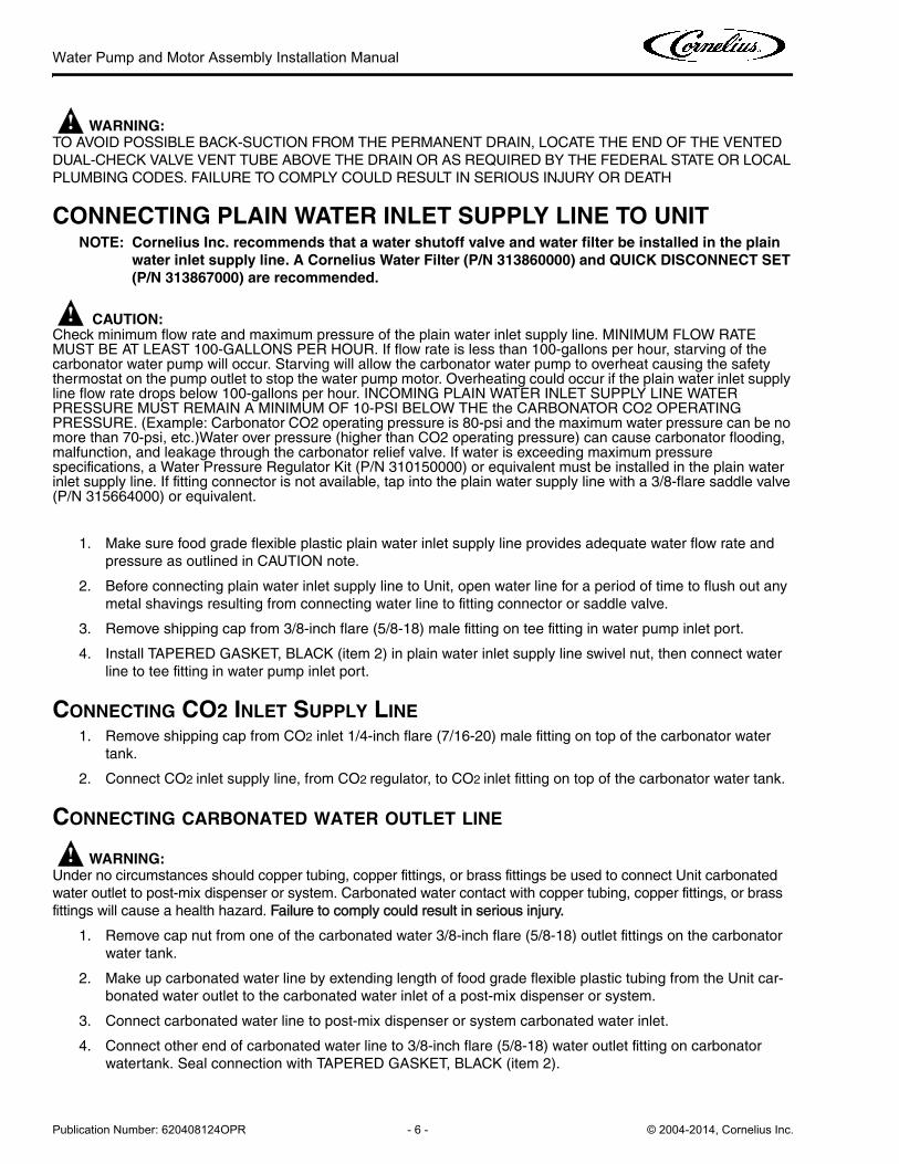
CONNECTING PLAIN WATER INLET SUPPLY LINE TO UNITNOTE: Cornelius Inc. recommends that a water shutoff valve and water filter be installed in the plain
water inlet supply line. A Cornelius Water Filter (P/N 313860000) and QUICK DISCONNECT SET
(P/N 313867000) are recommended.
CAUTION:!Check minimum flow rate and maximum pressure of the plain water inlet supply line. MINIMUM FLOW RATE MUST BE AT LEAST 100-GALLONS PER HOUR. If flow rate is less than 100-gallons per hour, starving of the carbonator water pump will occur. Starving will allow the carbonator water pump to overheat causing the safety thermostat on the pump outlet to stop the water pump motor. Overheating could occur if the plain water inlet supply line flow rate drops below 100-gallons per hour. INCOMING PLAIN WATER INLET SUPPLY LINE WATER PRESSURE MUST REMAIN A MINIMUM OF 10-PSI BELOW THE the CARBONATOR CO2 OPERATING PRESSURE. (Example: Carbonator CO2 operating pressure is 80-psi and the maximum water pressure can be no more than 70-psi, etc.)Water over pressure (higher than CO2 operating pressure) can cause carbonator flooding, malfunction, and leakage through the carbonator relief valve. If water is exceeding maximum pressure specifications, a Water Pressure Regulator Kit (P/N 310150000) or equivalent must be installed in the plain water inlet supply line. If fitting connector is not available, tap into the plain water supply line with a 3/8-flare saddle valve (P/N 315664000) or equivalent.
1. Make sure food grade flexible plastic plain water inlet supply line provides adequate water flow rate and
pressure as outlined in CAUTION note.
2. Before connecting plain water inlet supply line to Unit, open water line for a period of time to flush out any
metal shavings resulting from connecting water line to fitting connector or saddle valve.
3. Remove shipping cap from 3/8-inch flare (5/8-18) male fitting on tee fitting in water pump inlet port.
4. Install TAPERED GASKET, BLACK (item 2) in plain water inlet supply line swivel nut, then connect water
line to tee fitting in water pump inlet port.
CONNECTING CO2 INLET SUPPLY LINE
1. Remove shipping cap from CO2 inlet 1/4-inch flare (7/16-20) male fitting on top of the carbonator water
tank.
2. Connect CO2 inlet supply line, from CO2 regulator, to CO2 inlet fitting on top of the carbonator water tank.
CONNECTING CARBONATED WATER OUTLET LINE
! WARNING:Under no circumstances should copper tubing, copper fittings, or brass fittings be used to connect Unit carbonated
water outlet to post-mix dispenser or system. Carbonated water contact with copper tubing, copper fittings, or brass
fittings will cause a health hazard. Failure to comply could result in serious injury.
1. Remove cap nut from one of the carbonated water 3/8-inch flare (5/8-18) outlet fittings on the carbonator
water tank.
2. Make up carbonated water line by extending length of food grade flexible plastic tubing from the Unit car-
bonated water outlet to the carbonated water inlet of a post-mix dispenser or system.
3. Connect carbonated water line to post-mix dispenser or system carbonated water inlet.
4. Connect other end of carbonated water line to 3/8-inch flare (5/8-18) water outlet fitting on carbonator
watertank. Seal connection with TAPERED GASKET, BLACK (item 2).

Water Pump and Motor Assembly Installation Manual
© 2004-2014, Cornelius Inc. - 7 - Publication Number: 620408124OPR
PREPARATION FOR OPERATION
CAUTION:!To prevent a fire hazard, no object should be placed or stored on top of the Unit.
Adjust Carbonator CO2 Regulator and Turn Water Inlet Supply Line On
CAUTION:!Before connecting CO2 regulator assembly to CO2 cylinder, turn regulator adjusting screw to the left (counterclockwise) until all tension is relieved from adjusting screw spring. Failure to comply could result in equipment damage.
1. Open (counterclockwise) CO2 cylinder valve slightly to allow lines to slowly fill with gas, then open the valve
fully to back-seat the valve. (Back-seating the valve prevents leakage around the valve shaft).
2. Adjust carbonator CO2 regulator to a nominal 80-psi.
3. Open one of the post-mix system dispensing valves to exhaust trapped air inside the carbonator tank.
CAUTION:!Never operate the carbonator with the water inlet supply line shutoff valve closed. ‘‘Dry running’’ the water pump will burn out the pump. A pump damaged in this manner is not covered by warranty.
4. Open water inlet supply line shutoff valve.
UNIT OPERATION
! WARNING:The Unit must be electrically grounded to avoid possible fatal electrical shock or serious injury to the operator. The
unit power cord is equipped with a three-prong plug. If a three hole (grounded) electrical outlet is not available, use on
approved method to ground the unit. Failure to comply could result in serious injury, death, or damage to the
equipment.
1. Connect electrical power to the Unit. The water pump will start and fill the carbonator tank with carbonated
water. The water pump stops when the carbonator tank is full.
2. Check for water and CO2 leaks and tighten any loose connections.

Water Pump and Motor Assembly Installation Manual
Publication Number: 620408124OPR - 8 - © 2004-2014, Cornelius Inc.
OPERATORS INSTRUCTIONS
PERIODIC INSPECTION
Checking CO2 Supply
Make sure CO2 cylinder regulator assembly 1800-psi gage indicator is not in shaded (‘‘change CO2 cylinder’’)
portion of dial. If so, CO2 cylinder is almost empty and must be replaced.
Checking for CO2 and Water Leaks
Check unit for CO2 and water leaks and if found, call a qualified service technician to repair as necessary.
WATER PUMP ANNUAL MAINTENANCE (OR AFTER WATER SYSTEM DISRUPTION)The water pump water strainer screen and liquid dual check valve must be inspected and cleaned at least once a
year under normal circumstances and after any water system disruption (plumbing work, earthquake, etc.). Call a
qualified service technician to Inspect and clean the strainer screen and liquid dual check valve.
IMPORTANT: A vented dual-check valve assembly is installed in the carbonator between the water
pump outlet and the water inlet to the carbonator tank. The vented dual-check valve
assembly vents carbonated water, and possibly CO2 gas out of a vent port upon failure
of the primary check valves. Should such venting occur, call a qualified service
technician to replace the vented dual-check valve assembly.
Figure 1. Wiring Diagram

Water Pump and Motor Assembly Installation Manual
© 2004-2014, Cornelius Inc. - 9 - Publication Number: 620408124OPR
TROUBLESHOOTING! WARNING:
Water and CO2 to the system must be turned off and the system depressurized prior to performing this service.
Failure to comply could result in serious injury, death or damage to the equipment.
Trouble Probable Cause Remedy
CARBONATOR WILL NOT OPER-ATE.
A. Power cord disconnected
B. Inoperative carbonator.
A. Call a qualified service technician.
B. Call a qualified service technician.
WATER PUMP MOTOR WILL NOT SHUT OFF.
A. Carbonator Internal Problem. A. Call a qualified service technician.
ERRATIC CYCLING OF CARBON-ATER
A. Carbonator Internal Problem. A. Call a qualified service technician.
WATER PUMP MOTOR OPER-ATES BUT WATER PUMP DOES NOT PUMP WATER
A. Carbonator Internal Problem
or a water supply line problem. A. Call a qualified service technician.
CARBONATOR CARBONATEWATER CAPACITY TOO LOW
A. Carbonator internal problems or a
water supply line problem.
B. Water filter Clogged.
A. Call a qualified service technician.
B. Replace water filter

Water Pump and Motor Assembly Installation Manual
Publication Number: 620408124OPR - 10 - © 2004-2014, Cornelius Inc.


Cornelius Inc.
www.cornelius.com