MODEL HD-P10000 PLANETARY WINCH · operating, service and maintenance manual model hd-p10000...
24
OPERATING, SERVICE AND MAINTENANCE MANUAL MODEL HD-P10000 PLANETARY WINCH CAUTION: READ AND UNDERSTAND THIS MANUAL BEFORE INSTALLATION AND OPERATION OF WINCH. SEE WARNINGS!
Transcript of MODEL HD-P10000 PLANETARY WINCH · operating, service and maintenance manual model hd-p10000...

OPERATING, SERVICE ANDMAINTENANCE MANUAL
MODEL HD-P10000PLANETARY WINCH
CAUTION: READ AND UNDERSTAND THIS MANUAL BEFORE INSTALLATION ANDOPERATION OF WINCH. SEE WARNINGS!

TABLE OF CONTENTS
INTRODUCTIONS . . . . . . . . . . . . . . . . . . . . . . . . . . . . . . . . . . . . . . . . . . . . . . . . . . . . . . . . . . . . . . . .1
WARRANTY INFORMATION . . . . . . . . . . . . . . . . . . . . . . . . . . . . . . . . . . . . . . . . . . . . . . . . . . . . . . . .1
SPECIFICATIONS . . . . . . . . . . . . . . . . . . . . . . . . . . . . . . . . . . . . . . . . . . . . . . . . . . . . . . . . . . . . . . . .1
WARNINGS . . . . . . . . . . . . . . . . . . . . . . . . . . . . . . . . . . . . . . . . . . . . . . . . . . . . . . . . . . . . . . . . . . . .1
WINCH MOUNTING . . . . . . . . . . . . . . . . . . . . . . . . . . . . . . . . . . . . . . . . . . . . . . . . . . . . . . . . . . . . . .2
CABLE INSTALLATION . . . . . . . . . . . . . . . . . . . . . . . . . . . . . . . . . . . . . . . . . . . . . . . . . . . . . . . . . . . .3
HYDRAULIC SYSTEM REQUIREMENTS . . . . . . . . . . . . . . . . . . . . . . . . . . . . . . . . . . . . . . . . . . . . . . .4
TYPICAL LAYOUT . . . . . . . . . . . . . . . . . . . . . . . . . . . . . . . . . . . . . . . . . . . . . . . . . . . . . . . . . . . . . . .4
PERFORMANCE CHARTS . . . . . . . . . . . . . . . . . . . . . . . . . . . . . . . . . . . . . . . . . . . . . . . . . . . . . . . . .4
OPERATION . . . . . . . . . . . . . . . . . . . . . . . . . . . . . . . . . . . . . . . . . . . . . . . . . . . . . . . . . . . . . . . . . . . .5
MAINTENANCE . . . . . . . . . . . . . . . . . . . . . . . . . . . . . . . . . . . . . . . . . . . . . . . . . . . . . . . . . . . . . . . . .5
TROUBLE SHOOTING GUIDE . . . . . . . . . . . . . . . . . . . . . . . . . . . . . . . . . . . . . . . . . . . . . . . . . . . . . . .6
OVERHAUL INSTRUCTIONS . . . . . . . . . . . . . . . . . . . . . . . . . . . . . . . . . . . . . . . . . . . . . . . . . . . . .7-12
DIMENSIONAL DRAWINGS . . . . . . . . . . . . . . . . . . . . . . . . . . . . . . . . . . . . . . . . . . . . . . . . . . . . .14-15
PARTS LIST AND PARTS DRAWINGS . . . . . . . . . . . . . . . . . . . . . . . . . . . . . . . . . . . . . . . . . . . . .16-19
LIMITED WARRANTY . . . . . . . . . . . . . . . . . . . . . . . . . . . . . . . . . . . . . . . . . . . . . . . . . . .BACK COVER

PLEASE READ THIS MANUAL CAREFULLYThis manual contains useful ideas for obtaining the most efficient operation from your Ramsey Winch, and safety proceduresone needs to know before operating a Ramsey Winch. Do not operate this winch until you have carefully read and understandthe "WARNING" and "OPERATION" sections of this manual.
WARRANTY INFORMATIONRamsey Winches are designed and built to exacting specifications. Great care and skill go into every winch we make. If theneed should arise, warranty procedure is outlined on the back of your self-addressed postage paid warranty card. Please readand fill out the enclosed warranty card and send it to Ramsey Winch Company. If you have any problems with your winch,please follow instructions for prompt service on all warranty claims. Refer to back page for limited warranty.
SPECIFICATIONS*
NOTE: The rated line pulls shown are for the winch only. Consult the wire rope manufacturer for wire rope ratings.
WARNINGS:A MOTOR SPOOL (OPEN CENTER) DIRECTIONAL CONTROL VALVE IS REQUIRED FOR BRAKE OPERATION.
CLUTCH MUST BE FULLY ENGAGED BEFORE STARTING THE WINCH.
DO NOT DISENGAGE CLUTCH UNDER LOAD.
DO NOT LEAVE CLUTCH ENGAGED WHEN WINCH IS NOT IN USE.
STAY OUT FROM UNDER AND AWAY FROM RAISED LOADS.
STAND CLEAR OF CABLE WHILE PULLING. DO NOT TRY TO GUIDE CABLE.
DO NOT EXCEED MAXIMUM LINE PULL RATINGS SHOWN IN TABLE.
DO NOT USE WINCH TO LIFT, SUPPORT, OR OTHERWISE TRANSPORT PERSONNEL.
A MINIMUM OF 5 WRAPS OF CABLE AROUND THE DRUM BARREL IS NECESSARY TO HOLD THE LOAD. CABLE CLAMP(SETSCREW) IS NOT DESIGNED TO HOLD LOAD.
IN CAR CARRIER APPLICATIONS, AFTER PULLING VEHICLE ON CARRIER, BE SURE TO SECURE VEHICLE TO CARRIERBED. DO NOT MAINTAIN LOAD ON WINCH CABLE WHILE TRANSPORTING VEHICLE. DO NOT USE WINCH AS A TIEDOWN.
WHEN PULLING A HEAVY LOAD PLACE A BLANKET, JACKET, OR TARPAULIN OVER THE CABLE FIVE OR SIX FEET FROMTHE HOOK.
AVOID CONDITIONS WHERE LOAD SHIFTS OR JERKS OCCUR, AS THEY MAY INDICATE A DANGEROUS SITUATION.
1
Rated Line Pull (lbs.) ……………………………………… 10,000
(Kg.) ……………………………………… 4,530
Gear Reduction 5.1:1
HD-P10000 STD 87 lbs. (39.5 Kg)
HD-P10000 "Y" 82 lbs. (37.2 Kg)
1 2 3 4
lbs. 10,000 8,300 7,100 6200
Kg. 4,530 3,760 3,220 2810
ft. 20 50 80 115
m 6 15 24 35
ft. 15 30 55 75
m 4 9 16 22
FPM 32 38 44 51
MPM 9.8 11.6 13.4 15.5
……………………………………………..
Weight (without cable)
* These specifications are based on recommended wire rope of 7/16" (11mm) EIPS cable and a 24.9 cu.in./Rev. motor.
LAYER OF CABLE
*Rated line pull per layer
HD-P10000 (STD. DRUM)
* Line Speed (at 15 GPM)
HD-P10000 ("Y" DRUM)
* Cable Capacity per Layer

WINCH MOUNTING
ESSENTIAL MOUNTING INSTRUCTIONS TO MAINTAIN ALIGNMENT OF PLANETARY WINCH COMPONENTS:
It is most important that this winch be mounted securely so that the three major sections (the motor end, the cabledrum, and the gear housing end) are properly aligned. Excessive bushing wear and difficulty in freespooling are usu-ally symptoms of misalignment.
In the as-installed condition, if the winch is mid-mounted, then at least one tie-plate must be attached to the mountingfeet at the bottom of the winch to maintain alignment. If the winch is foot mounted then at least one tie-plate mustremain mounted at midpoint of winch to maintain alignment. It is always preferred to used BOTH tie-plates in the finalinstalled configuration.
Angle Mounting Kit, P/N 251006 (for Std. Drum) or 251007 (for “Y” drum), is recommended for maximum ease inmounting the winch. The angle kit will allow the winch to be mounted in upright or midmount applications and willmeet the criteria of serving as a solid and true mounting surface.
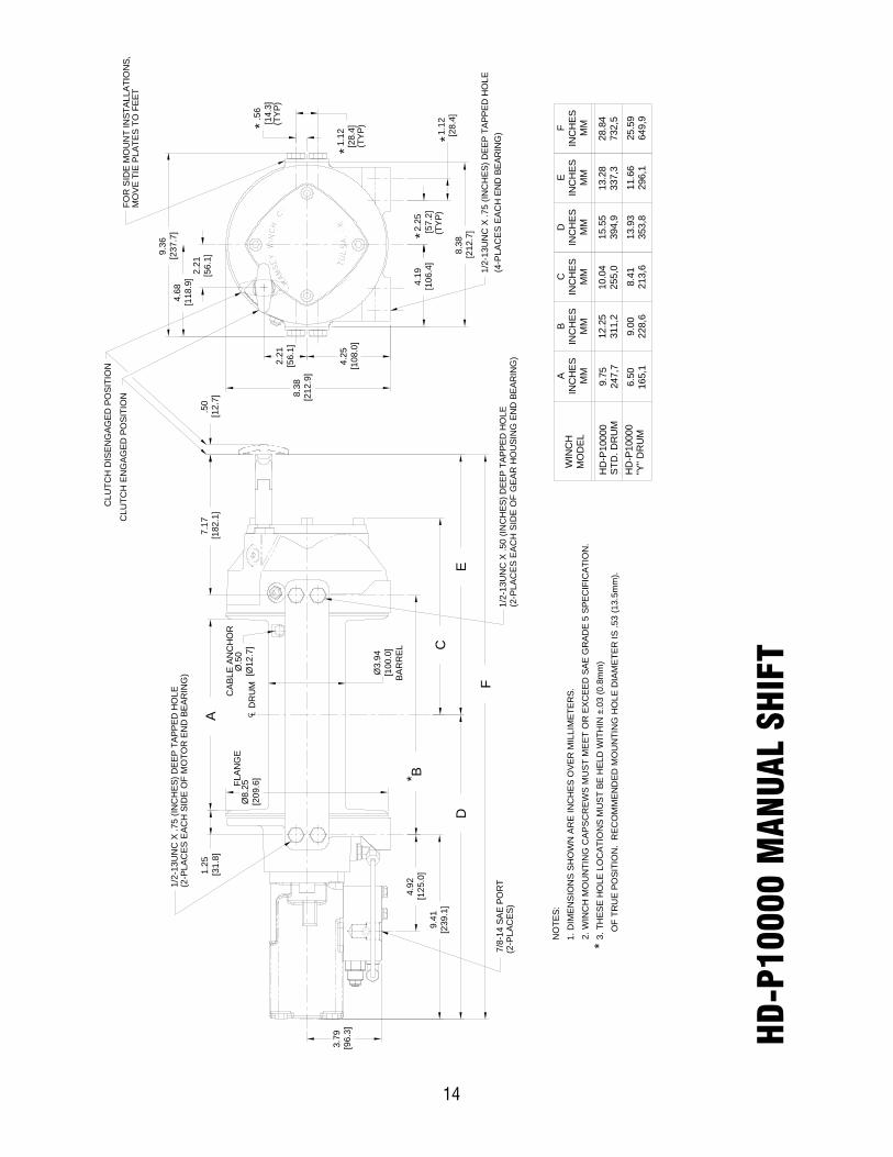
When mounting the winch with other than the recommended Ramsey Angle Kit, the mounting hole patterns describedin the Dimensional drawings on pages 14-15 should be used. The mounting surface must be flat within .015 inchand sufficiently stiff to resist flexing. If a steel plate is used for foot mounting, it should be .750 inch thick. For thismounting application eight (8) 1/2-13NC x 1-1/2” long grade 5 capscrews with lockwashers will be needed to mountwinch. Capscrews should be tightened to 55 ft-lb (75 Nm) torque.
NOTE: If angles or a steel plate are used in mounting winch, tie-plates provided with winch are to be attached to theremaining mounting pads, whether they be side or foot.
* CAUTION: If longer bolts (minimum grade 5) are substituted to mount winch or to mount a roller guide at theside mount pads, bolt length must be such as to allow a minimum of .50 inch thread length engagement in thetapped holes in side of each end bearing. Refer to pages 14-15. Use of excessive length bolts will damage thewinch and prevent freespool of the drum. Torque bolts to 55 ft-lbs. (75 Nm).
2
MID MOUNT
FOOT MOUNT
SEE BOLT LENGTHCAUTION BELOW *
TIEPLATE AT FOOT (BASE) LOCATION
TIEPLATE AT SIDE LOCATION
GEAR HOUSING ENDCABLE DRUMMOTOR END
CABLE INSTALLATION
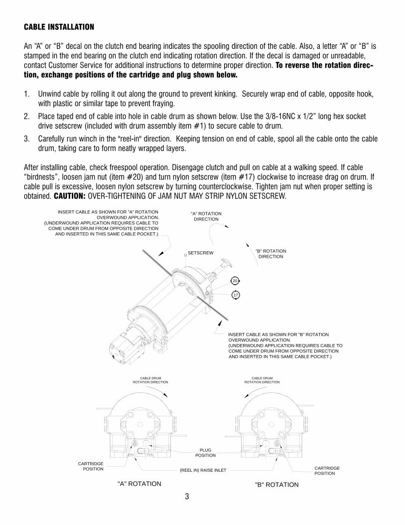
An “A” or “B” decal on the clutch end bearing indicates the spooling direction of the cable. Also, a letter “A” or “B” isstamped in the end bearing on the clutch end indicating rotation direction. If the decal is damaged or unreadable,contact Customer Service for additional instructions to determine proper direction. To reverse the rotation direc-tion, exchange positions of the cartridge and plug shown below.
1. Unwind cable by rolling it out along the ground to prevent kinking. Securely wrap end of cable, opposite hook,with plastic or similar tape to prevent fraying.
2. Place taped end of cable into hole in cable drum as shown below. Use the 3/8-16NC x 1/2” long hex socketdrive setscrew (included with drum assembly item #1) to secure cable to drum.
3. Carefully run winch in the "reel-in" direction. Keeping tension on end of cable, spool all the cable onto the cabledrum, taking care to form neatly wrapped layers.
After installing cable, check freespool operation. Disengage clutch and pull on cable at a walking speed. If cable“birdnests”, loosen jam nut (item #20) and turn nylon setscrew (item #17) clockwise to increase drag on drum. Ifcable pull is excessive, loosen nylon setscrew by turning counterclockwise. Tighten jam nut when proper setting isobtained. CAUTION: OVER-TIGHTENING OF JAM NUT MAY STRIP NYLON SETSCREW.
3
INSERT CABLE AS SHOWN FOR "A" ROTATIONOVERWOUND APPLICATION.
(UNDERWOUND APPLICATION REQUIRES CABLE TOCOME UNDER DRUM FROM OPPOSITE DIRECTION
AND INSERTED IN THIS SAME CABLE POCKET.)
INSERT CABLE AS SHOWN FOR "B" ROTATIONOVERWOUND APPLICATION.(UNDERWOUND APPLICATION REQUIRES CABLE TOCOME UNDER DRUM FROM OPPOSITE DIRECTIONAND INSERTED IN THIS SAME CABLE POCKET.)
"B" ROTATIONDIRECTION
"A" ROTATIONDIRECTION
SETSCREW
17
20
PLUGPOSITION
CARTRIDGEPOSITION
CARTRIDGEPOSITION
CABLE DRUMROTATION DIRECTION
CABLE DRUMROTATION DIRECTION
"B" ROTATION"A" ROTATION
(REEL IN) RAISE INLET

HYDRAULIC SYSTEM REQUIREMENTS
Refer to the performance charts below to properly match your hydraulic system to the winch performance. Thecharts consist of:
(1) Line Pull first layer (lb.) vs. Working Pressure (PSI)
(2) Line Speed, first layer (FPM) vs. flow (GPM)
SYSTEM REQUIREMENTS
MOTOR SPOOL (OPEN CENTER) CONTROL VALVE REQUIRED2100 PSI RELIEF VALVE SETTING
15 GPM FLOW RATEDO NOT EXCEED 20 GPM--MOTOR AND WINCH MAY BE DAMAGED
10 MICRON NOMINAL FILTRATION
B
TYPICAL LAYOUT
WITH BRAKE RELEASE SHUTTLE
MOTOR
BRAKEPORT
A
SYSTEMRELIEF
3 POSITION4 WAY VALVE
(MOTOR SPOOL)
MAX. FLOW &PRESSURE ATRATED LOAD:15 GPM2500 PSI
HIGH PRESSURE LINE(.50 I.D. MINIMUM) LOW PRESSURE LINE
(.75 I.D. MINIMUM)
PUMP
PORT CONTROL
(DUAL CART.VALVE OPTION)
4
WORKING PRESSURE (PSI) AT 15 GPM FLOW (GPM)
LIN
E PU
LL-F
IRST
LAY
ER (L
B)
LIN
E SP
EED
-FIR
ST L
AYER
(FPM
)
0 5 10 150
5
10
15
00
1000
2000
3000
4000
5000
6000
7000
8000
1000 2000 2500
BASED ON 24.9 CU. IN. MOTOR
1500500
PERFORMANCE CHARTS
9000
10000
NOTE: Dual counterbalance valve version at Maximum Flow will require an increased working pressure of 150 PSI.

OPERATION
The best way to get acquainted with how your winch operates is to make test runs before you actually use it. Planyour test in advance. Remember, you hear your winch as well as see it operate. Get to recognize the sounds of a lightsteady pull, a heavy pull, and sounds caused by load jerking or shifting. Avoid conditions where load shifts or jerksoccur, as they may indicate a dangerous situation.
The uneven spooling of cable, while pulling the load, is not a problem, unless there is a cable pileup on one end ofthe drum. If this happens, reverse the winch to relieve the load, and move your anchor point further to the center ofthe vehicle. After the job is done you can unspool and rewind for a neat lay of the cable.
When pulling a heavy load, place a blanket, jacket, and tarpaulin over the cable about five or six feet behind the hook.In the event of a broken cable, this will slow the snap back of the cable and could prevent serious injury.
The winch clutch allows rapid unspooling of the cable, from the cable drum, for hooking onto the load. The clutch isoperated by the clutch shifter lever or air shifter.
WARNING: DO NOT DISENGAGE CLUTCH UNDER LOAD!
MANUAL CLUTCH SHIFTER (Refer to dimensional drawing page 14):
TO DISENGAGE CLUTCH: Run the winch in the reverse (reel out) direction until the load is off the cable. Pull handleout and rotate 90°. With handle in the “DISENGAGED” position, cable may now be free-spooled from the drum.
TO ENGAGE CLUTCH: Pull handle out, rotate 90° and release handle. Run the winch in reverse until the clutch handlesnaps fully into the “ENGAGED” position. DO NOT attempt to pull a load unless the handle is fully at the “ENGAGED”position. If manual shift indicator light is present, the green light is lit when clutch is fully “ENGAGED”. DO NOTattempt to pull a load unless the green light is lit. To install light to the vehicle electrical system refer to the ElectricalSchematic on page 15.
AIR CYLINDER CLUTCH SHIFTER (Refer to the dimensional drawing page 15):
TO DISENGAGE CLUTCH: Run the winch in the reverse (reel out) direction until load is off the cable. Apply air pres-sure to the .125-27 NPT port: 80 PSI (min.)-150 PSI (max.). CAUTION: PRESSURE MUST NOT EXCEED 150 PSI.
TO ENGAGE CLUTCH: Remove air pressure from the cylinder (a return spring engages the plunger). Run winch inreverse until the clutch engagement indicator light (green light) is lit. To install light to the vehicle electrical systemrefer to the Electrical Schematic on page 15.
MAINTENANCE
1. Inspect the cable for damage and lubricate frequently. If the cable becomes frayed with broken strands, replaceimmediately. Cable and hook assembly (100’ long cable) P/N 524118 (“Y” drum) or (150’ long cable) P/N524119 (STD drum) may be purchased from a Ramsey distributor.
2. Check that the clutch is fully engaging. See OPERATION instructions, above, for the appropriate clutch shifter.FOR MANUAL CLUTCH ONLY: Monthly, disengage clutch, put several drops of oil on the clutch handle shaft andwork clutch handle IN and OUT several times to lubricate inside the shifter assembly.
3. Check to see that the drum cable does not overrun (“birdnest”) when freespooling. Refer to page 3 if it does.
4. Replace drum bushings and seals if seals begin to seep grease. Refer to the Overhaul Instructions, pages 7-12.Add additional lubricant, Mobilith SHC 007, to gears and drum bearings if required.
5

TROUBLESHOOTING GUIDE
6
CONDITIONS POSSIBLE CAUSE CORRECTION/ACTION
DRUM WILL NOT ROTATEAT NO LOAD
Winch not mounted squarely, causing end bearingto bind up
Check mounting. Refer to Winch Mounting, page 2.
Gears damaged Inspect and replace damaged gears
DRUM WILL NOT ROTATEUNDER LOAD
Winch not mounted squarely, causing end bearingto bind up
Check mounting. Refer to Winch Mounting, page 2.
Load greater than rated capacity of winch Refer to Specifications page 1 for line pull rating.
Low hydraulic system pressure Check pressure. Refer to Hydraulic Systems per-formance charts page 4.
WINCH RUNS TOO SLOW Low hydraulic system flow rate Check flow rate. Refer to Systerm Requirements andTypical Layout page 4.
Motor worn out Replace motor
DRUM WILL NOTFREESPOOL
Clutch not disengaged. Check Adjustment of ManualShifter, page 10.
Check Operation, page 5.
Winch not mounted squarely, causing end bearingto bind up
Check mounting. Refer to Winch Mounting, page 2.
Side mounted bolts too long, causing binding of ringgear (Item #15, page 16).
Check bolt length. Bolt thread MUST NOT engagethreaded holes in sides of end bearing more than the.50 inch thread depth in the end bearing.
BRAKE WILL NOT HOLD Incorrect directional control valve (cylinder spool-closed center)
Use only a motor spool (open center) control valve.
LOAD DRIFTS Excessive Backpressure (100 PSI Max.) Check for restrictions in hydraulic system. Refer toSystem Requirements and Typical Layout page 4.
CABLE BIRDNESTS WHENCLUTCH IS DISENGAGED
Drag screw improperly adjusted Adjust nylon drag screw. Refer to Cable Installation,page 3.
EXCESSIVE NOISE Hydraulic system flow too high Check flow rate. Refer to Typical Layout page 4.
Drum in bind, winch not mounted squarely Check mounting. Refer to Winch Mounting, page 2.
DRUM CHATTERS IN“REEL IN” DIRECTION
Low hydraulic system flow rate Check flow rate. Refer to Typical Layout page 4.
Low hydraulic system relief pressure setting Check relief valve setting.
OIL LEAKS FROMBREATHER VENT UNDERMOTOR END BEARING
Damaged brake o-rings, backup rings, or sealingsurfaces
Disassemble brake and inspect. See OverhaulInstructions, pg. 8.
7
43
44
26
45 23
15
26
25
28
30
24
19
48
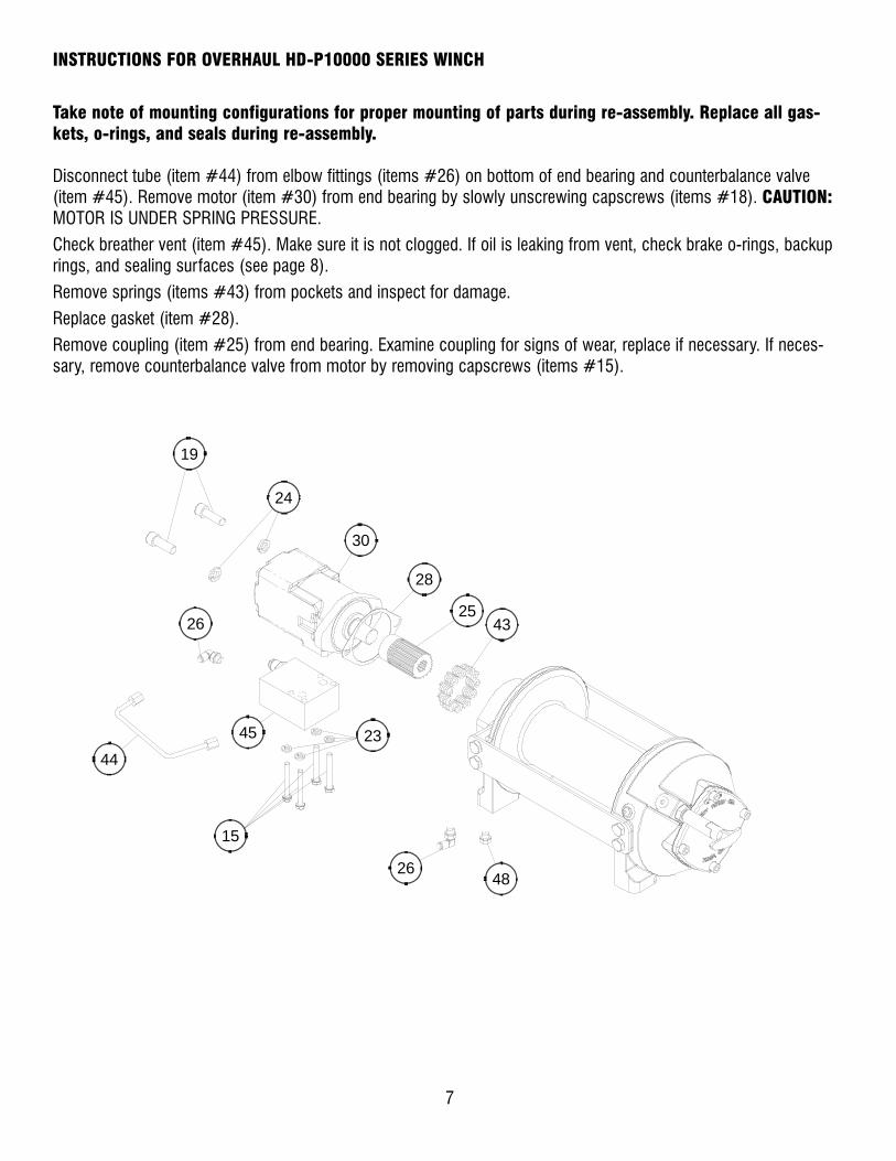
INSTRUCTIONS FOR OVERHAUL HD-P10000 SERIES WINCH
Take note of mounting configurations for proper mounting of parts during re-assembly. Replace all gas-kets, o-rings, and seals during re-assembly.
Disconnect tube (item #44) from elbow fittings (items #26) on bottom of end bearing and counterbalance valve(item #45). Remove motor (item #30) from end bearing by slowly unscrewing capscrews (items #18). CAUTION:MOTOR IS UNDER SPRING PRESSURE.
Check breather vent (item #45). Make sure it is not clogged. If oil is leaking from vent, check brake o-rings, backuprings, and sealing surfaces (see page 8).
Remove springs (items #43) from pockets and inspect for damage.
Replace gasket (item #28).
Remove coupling (item #25) from end bearing. Examine coupling for signs of wear, replace if necessary. If neces-sary, remove counterbalance valve from motor by removing capscrews (items #15).

5
4
3533
7
3136
3234
6
42
49
Remove retaining rings (items #42 and 49) with screwdriver.
Remove brake parts from end bearing. NOTE POSITION OF O-RINGS AND BACKUP RINGS BEFORE REMOVAL. Examine brake discs (items #5) and stators (items #4) for signs of wear, and replace if necessary.
Examine o-rings (items #31 and 32) and backup rings (items #34 and 36) in brake piston (item #6), as well
as o-ring (item #33) and backup ring (item #35) in backup brake piston (item #7) for signs of wear. Remove o-rings and backup rings from grooves in brake piston or backup brake piston and replace if necessary.
8

9
Remove tie plates (items #12) from end bearings by unscrewing capscrews (items #16). Slide motor end bearing(item #10) and drum (item #1) from gear housing end bearing.
Remove input shaft (item #11) from end bearing. Inspect shaft and and output sun gear (item #8) for damage andreplace if necessary. To remove the output sun gear, remove the snap rings (items #41) and thrust washer (item#47) and pull off the end of the shaft.
Remove bushing (item #14) and o-ring (item #37) from motor end bearing. Place new, well-oiled o-ring into grooveinside of end bearing and press new bushing onto end bearing.
14
37
10
41
478
111
12
16
12
16
Remove seal (item #40) from gear housing end bearing (item#9). Loosen nut (item #22) and remove nylon setscrew (item#18). Remove ring gear from gear housing end bearing, if nec-essary. Remove bushing (item #13) from end bearing.
Press new bushing into end bearing. Install ring gear, thennylon setscrew and nut. Ring gear must be fully seated in endbearing and slot in ring gear MUST NOT be aligned with clutchshifter hole. Install new seal in end bearing, with sharp edge ofseal outward.
1822
40
29
913

10
Generously apply grease (MOBILITH SHC 007) to teeth of ring gear (item #29), teeth of planet gears in drum (item #1), and tobushing (item #13) in gear housing end bearing. Apply a small amount of grease to base of bushing (item #14) on motor endbearing. Apply grease to teeth of output sun gear (item #8) and input shaft (item #11).
Place end of shaft with output sun gear on it into drum. Rotate shaft to engage planet gears with output sun gear. Place GearEnd Bearing on Drum and engage planet gears with ring gear.
Assemble motor end bearing (item #10) to drum assembly and use tie plates (items #12) and capscrews (items #16) to holdboth end bearings together. Tighten capscrews to 55 ft-lbs (75 Nm).
If necessary, remove and replace the shifter assembly (manual, item #2, or air-cylinder, item #3), as follows:
MANUAL CLUTCH SHIFTER ASSEMBLY
Loosen setscrew (item #20) and jam nut on shifter assembly, then unscrew shifter assembly (item #2). Be sure slot in ringgear is not aligned with clutch shifter hole. Rotate drum, if necessary, to ensure hole and slot are not aligned.
Reinstall shifter assembly with plunger, jam nut, and handle positioned in gear housing as shown below. Thread assembly (withhandle engaged in cylinder slot) into the gear housing. Pull drum toward the gear end bearing housing to remove play. Holddrum in position and continue threading the shifter assembly in until the gap between the end of the handle and cylinder is
7/16 +0-1/16 inch and handle is in the horizontal position (see below). Note: This gap will vary with drum endplay. With the
drum pulled against the motor end housing, the gap should be 3/8 inch.
Lightly tighten jam nut. Rotate drum until handle snaps fully into the engaged position. Pull handle out and rotate 90°. Verify thatdrum can be rotated freely (at least one full revolution) with clutch shifter at the DISENGAGED position. Securely tighten jam nutwhile holding the handle. Tighten setscrew (item #20) securely. Re-check clutch operation as described on page 5.
AIR CYLINDER SHIFTER ASSEMBLY
Loosen set screw (item #20) to remove shifter assembly (item #3). To reinstall, place 1 or 2 shims (items #44) over plungerand thread shifter assembly into gear end housing. Add or remove shims to orient ports for pneumatic connections. Portsshould point down (below horizontal). Tighten setscrew. Check for clutch operation as described on page 5.
If the light assembly (item #2) or light switch (item #48) needs to be replaced, refer to the schematic on page 15 for electricalconnections and disassemble and reassemble as shown below.
JAM NUT
PLUNGER
AIR-CYLINDER CLUTCH SHIFTER
MANUAL CLUTCH SHIFTER
MANUAL CLUTCH ADJUSTMENT
HANDLE (HORIZONTAL)
CYLINDER
23
4
41
2
3
44
21
2
20
9
42
48LIGHT SWITCH
LIGHT ASSEMBLY

Set winch with gear housing end down on work surface. Install well-oiled o-rings and backup rings into grooves on outside of brake piston and backup brake piston as shown in cross-section A-A below.
Piston, backup piston, brake discs and stators must be clean and free of grease and oil.
Insert brake discs (item #5) and stators (item #4) into gear end alternating, with stators first and last. Insert backup brake piston (item #7) into motor end and insert brake piston (item #6) into it. Apply even pressure on piston when installing. Install retaining rings (items #42 and 49) into grooves in motor end housing.
11
5
4
3533
7
3136
3234
6
42
49
A
A
SECTION A-A6 7
34 32 33 35
31
36
MOTOR SIDE
DRUM SIDE
12
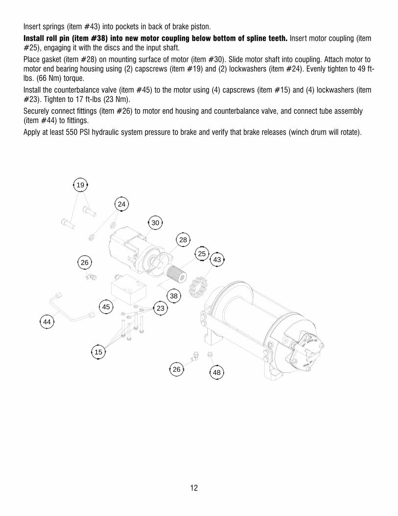
Insert springs (item #43) into pockets in back of brake piston.
Install roll pin (item #38) into new motor coupling below bottom of spline teeth. Insert motor coupling (item#25), engaging it with the discs and the input shaft.
Place gasket (item #28) on mounting surface of motor (item #30). Slide motor shaft into coupling. Attach motor tomotor end bearing housing using (2) capscrews (item #19) and (2) lockwashers (item #24). Evenly tighten to 49 ft-lbs. (66 Nm) torque.
Install the counterbalance valve (item #45) to the motor using (4) capscrews (item #15) and (4) lockwashers (item#23). Tighten to 17 ft-lbs (23 Nm).
Securely connect fittings (item #26) to motor end housing and counterbalance valve, and connect tube assembly(item #44) to fittings.
Apply at least 550 PSI hydraulic system pressure to brake and verify that brake releases (winch drum will rotate).
38
43
45 23
15
25
28
30
24
19
26
26
44
48

13
NOTES
14
BA
RR
EL
CLU
TCH
EN
GA
GED
PO
SITI
ON
CLU
TCH
DIS
EN
GAG
ED P
OSI
TIO
N
1/2-
13U
NC
X .7
5 (IN
CH
ES) D
EEP
TAPP
ED H
OLE
(2-P
LAC
ES E
ACH
SID
E O
F M
OTO
R E
ND
BE
ARIN
G)
7/8-
14 S
AE
POR
T(2
-PLA
CES
)(2
-PLA
CE
S E
AC
H S
IDE
OF
GE
AR H
OU
SIN
G E
ND
BEA
RIN
G)
1/2-
13U
NC
X .5
0 (IN
CH
ES) D
EEP
TAPP
ED H
OLE
NO
TES:
1. D
IME
NS
ION
S S
HO
WN
AR
E IN
CH
ES O
VER
MIL
LIM
ETER
S.2.
WIN
CH
MO
UN
TIN
G C
AP
SC
RE
WS
MU
ST
ME
ET
OR
EXC
EED
SAE
GR
ADE
5 SP
ECIF
ICAT
ION
.3.
TH
ESE
HO
LE L
OC
ATIO
NS
MU
ST
BE H
ELD
WIT
HIN
±.0
3 (0
.8m
m)
O
F TR
UE
POSI
TIO
N.
REC
OM
ME
ND
ED M
OU
NTI
NG
HO
LE D
IAM
ETE
R IS
.53
(13.
5mm
).
FLA
NG
E
*
1.25
[31.
8]7.
17 [1
82.1
]
Ø3.
94 [1
00.0
]
DR
UM
C L
(TY
P)1.
12 [2
8.4]
*(TY
P)
(TY
P)
1.12
[28.
4]*
*
4.68
[118
.9]
9.36
[237
.7]
MO
VE
TIE
PLAT
ES T
O F
EET
FOR
SID
E M
OU
NT
INST
ALLA
TIO
NS,
8.38
[212
.9]
1/2-
13U
NC
X .7
5 (IN
CH
ES) D
EEP
TAPP
ED H
OLE
(4-P
LAC
ES
EA
CH
EN
D B
EAR
ING
)
CA
BLE
AN
CH
OR
** B
4.92
[125
.0]
9.41
[239
.1]
3.79
[96.
3]
F
Ø8.
25 [2
09.6
]
A.5
0 [1
2.7]
DE
C
2.21
[56.
1]
2.21
[56.
1]
4.25
[108
.0]
8.38
[212
.7]
4.19
[106
.4]
2.25
[57.
2]
.56
[14.
3]
Ø.5
0 [Ø
12.7
]
213,
68.
41
255,
010
.04
228,
69.
00
311,
212
.25
165,
16.
5024
7,7
9.75
CIN
CH
ESM
M
BIN
CH
ESM
M
A MM
INC
HES
HD
-P10
000
HD
-P10
000
MO
DEL
WIN
CH
MM
INC
HES
D
MM
INC
HES
E
15.5
539
4,9
13.9
335
3,8
13.2
833
7,3
11.6
629
6,1
STD
. DR
UM
"Y" D
RU
M64
9,9
25.5
9
732,
528
.84
FIN
CH
ESM
M
HD
-P10
000
MAN
UAL
SHIF
T

BAR
REL
1/2-
13U
NC
X .7
5 (IN
CH
ES) D
EEP
TAPP
ED H
OLE
(2-P
LAC
ES E
ACH
SID
E O
F M
OTO
R E
ND
BEA
RIN
G)
7/8-
14 S
AE P
OR
T(2
-PLA
CES
)(2
-PLA
CES
EAC
H S
IDE
OF
GEA
R H
OU
SIN
G E
ND
BEA
RIN
G)
1/2-
13U
NC
X .5
0 (IN
CH
ES) D
EEP
TAPP
ED H
OLE
NO
TES:
1. D
IMEN
SIO
NS
SHO
WN
AR
E IN
CH
ES O
VER
MIL
LIM
ETER
S.2.
WIN
CH
MO
UN
TIN
G C
APSC
REW
S M
UST
MEE
T O
R E
XCEE
D S
AE G
RAD
E 5
SPEC
IFIC
ATIO
N.
3. T
HES
E H
OLE
LO
CAT
ION
S M
UST
BE
HEL
D W
ITH
IN ±
.03
(0.8
mm
)
OF
TRU
E PO
SITI
ON
. R
ECO
MM
END
ED M
OU
NTI
NG
HO
LE D
IAM
ETER
IS .5
3 (1
3.5m
m).
FLAN
GE
1.25
[31.
8]
Ø3.
94 [1
00.0
]
DR
UM
C L
(TYP
)1.
12 [2
8.4]
1.12
[28.
4]
4.68
[118
.9]
9.36
[237
.7]
MO
VE T
IE P
LATE
S TO
FEE
TFO
R S
IDE
MO
UN
T IN
STAL
LATI
ON
S,
1/2-
13U
NC
X .7
5 (IN
CH
ES) D
EEP
TAPP
ED H
OLE
(4-P
LAC
ES E
ACH
EN
D B
EAR
ING
)
CAB
LE A
NC
HO
R
2.21
[56.
1]
12V
BATT
ERY
IND
ICAT
OR
LIG
HT
(ON
WH
EN C
LUTC
HIS
EN
GAG
ED)
SWIT
CH
BUTT
CO
NN
ECTO
RAT
TAC
H T
O G
RO
UN
D (1
6 G
A.W
IRE
SUPP
LIED
BY
CU
STO
MER
)
ELE
CTR
ICA
LS
CH
EM
ATI
CAT
TAC
H T
O P
TO IN
DIC
ATO
R S
WIT
CH
TO
REC
EIVE
12V
DC
WH
EN P
TO IS
EN
GAG
ED.
NO
TE: L
IGH
T SH
OU
LD B
E "O
N" W
HEN
CLU
TCH
ISEN
GAG
ED A
ND
"OFF
" WH
EN C
LUTC
H IS
DIS
ENG
AGED
.
ATTA
CH
TO
12V
DC
(+)
(SEE
ELE
CTR
ICAL
SC
HEM
ATIC
)
ATTA
CH
TO
GR
OU
ND
(-)
(SEE
ELE
CTR
ICAL
SC
HEM
ATIC
)
1/8-
27N
PT P
OR
T(C
ON
NEC
T 80
TO
150
PSI
**PR
ESSU
RE
LIN
E TO
DIS
ENG
AGE
CLU
TCH
)
IND
ICAT
OR
LIG
HT
SWIT
CH
B4.
92 [1
25.0
]9.
41 [2
39.1
]
3.79
[96.
3]
F
Ø8.
25 [2
09.6
]
A
DE
C
2.21
[56.
1]
4.25
[108
.0]
8.38
[212
.7]
4.19
[106
.4]
2.25
[57.
2]
.56
[14.
3]
3.59
[91.
1]
9.15
[232
.4]
Ø.5
0 [Ø
12.7
]
MM
INC
HES
F
28.2
871
8,3
24.9
963
4,7
"Y" D
RU
M
STD
. DR
UM
240,
59.
47
323,
112
.72
353,
813
.93
394,
915
.55
EIN
CH
ESM
M
DIN
CH
ESM
MW
INC
HM
OD
EL
HD
-P10
000
HD
-P10
000
INC
HES
MMA
MM
INC
HES
B
MM
INC
HES
C
9.75
247,
7
6.50
165,
1
12.2
531
1,2
9.00
228,
6
10.0
425
5,0
8.41
213,
6
HD
-P10
000
AIR
SHIF
T
15

9
101523
45
26
44
19
2430
38
28
2542
43
6
3432
3631
7
3335
4
5
37
14
26
12
16
18 2220
2
3946
12
16
40
29
8
41
47
11
13
1
27
3
21
17
48
49
16

Item
No.
Q
uant
ity
Part
No.
Des
crip
tion
Ite
m N
o.
Qua
ntity
Pa
rt N
o. D
escr
iptio
n 1
1 23
4207
D
RU
M A
SS
Y S
TD
27
1
4422
12
GA
SK
ET-
GE
AR
HO
US
ING
CO
VE
R
1
2342
08
DR
UM
AS
SY
"Y"
28
1
4422
23
GA
SK
ET-
MO
TOR
FLA
NG
E
2 1
2760
48
SH
IFTE
R A
SS
Y
29
1
4440
84
GE
AR
-RIN
G
3 1
3281
64
CO
VE
R-G
EA
R H
OU
SIN
G
30
1
4580
79
MO
TOR
-HYD
. 4
6 33
0011
S
TATO
R-B
RA
KE
31
1 46
2067
O
-RIN
G P
ISTO
N-S
M.
5 5
3300
12
DIS
C-B
RA
KE
32
1 46
2068
O
-RIN
G P
ISTO
N-L
G.
6 1
3300
13
PIS
TON
-BR
AK
E
33
1
4620
69
O-R
ING
BA
CK
UP
PIS
TON
7
1 33
0014
P
ISTO
N-B
AC
KU
P B
RA
KE
34
1 46
2070
R
ING
-BA
CK
UP
PIS
TON
-LG
8
1 33
4174
G
EA
R-O
UTP
UT,
SU
N
35
1
4620
71
RIN
G-B
AC
KU
P B
AC
KU
P P
ISTO
N
9 1
3383
27
EN
D B
EA
RIN
G-G
EA
R H
OU
SIN
G
36
1
4620
72
RIN
G-B
AC
KU
P P
ISTO
N-S
M
10
1 33
8358
E
ND
BE
AR
ING
-MO
TOR
37
1 46
2073
O
-RIN
G
11
1 35
7177
S
HA
FT-IN
PU
T S
TD D
RU
M
38
1
4700
33
SP
IRO
L P
IN
3571
76
SH
AFT
-INP
UT
"Y" D
RU
M
39
1
4720
52
PLU
G
12
2 39
5427
P
LATE
-TIE
STD
DR
UM
40
1 48
6080
S
EA
L
39
5426
P
LATE
-TIE
"Y" D
RU
M
41
2
4900
03
SN
AP
RIN
G
13
1 41
2085
B
US
HIN
G-D
RU
M
42
1
4900
49
RIN
G-IN
TER
NA
L R
ETA
ININ
G
14
1 41
2109
B
US
HIN
G-D
RU
M, M
OTO
R E
ND
43
11
4941
24
SP
RIN
G-B
RA
KE
15
4 41
4159
C
AP
SC
RE
W-5
/16-
18U
NC
X 2
1/2
", H
EX
HE
AD
, ZIN
C, G
R5
44
1
5091
32
TUB
E-B
RA
KE
RE
LEA
SE
(PO
RTS
DO
WN
) 16
8
4145
81
CA
PS
CR
EW
-1/2
-13N
C X
3/4
", H
EX
HE
AD
, ZIN
C, G
R5
50
9131
TU
BE
-BR
AK
E R
ELE
AS
E (P
OR
TS U
P)
17
4 41
4901
C
AP
SC
RE
W-3
/8-1
6NC
X 3
/4",
HE
X S
OC
KE
T H
EA
D
45
1
5160
41
VA
LVE
-MO
TOR
CO
NTR
OL
(A R
OTA
TIO
N)
18
1 41
4926
S
ETS
CR
EW
-3/8
-16N
C X
1",
SO
CK
ET
HE
AD
, NY
LON
5160
42
VA
LVE
-MO
TOR
CO
NTR
OL
(B R
OTA
TIO
N)
19
2 41
4954
C
AP
SC
RE
W-1
/2-1
3NC
X 1
3/4
", S
OC
KE
T H
EA
D, Z
INC
51
6043
V
ALV
E-M
OTO
R C
ON
TRO
L S
IDE
PO
RTS
(A R
OT)
20
1
4160
16
SE
TSC
RE
W-1
/4-2
0NC
X 1
/4",
HE
X S
OC
KE
T H
EA
D C
UP
5160
44
VA
LVE
-MO
TOR
CO
NTR
OL
SID
E P
OR
TS (B
RO
T)
21
2 41
6239
S
CR
EW
-#10
-24N
C X
3/8
", H
EX
SO
CK
ET
BU
TTO
N H
EA
D
51
6013
V
ALV
E-M
OTO
R C
ON
TRO
L (D
UA
L C
AR
T.)
22
1 41
8036
N
UT-
3/8-
16 N
C, H
EX
JA
M, Z
INC
46
1 51
8037
TH
RU
ST
WA
SH
ER
23
4
4181
63
LOC
KW
AS
HE
R-5
/16
ME
D S
EC
T, Z
INC
47
1 51
8047
TH
RU
ST
WA
SH
ER
24
2
4182
18
LOC
KW
AS
HE
R-1
/2 ID
ME
D S
EC
T, Z
INC
48
1 45
6038
B
RE
ATH
ER
VE
NT
25
1 43
1020
C
OU
PLI
NG
-MO
TOR
49
1 49
0066
R
ING
-INTE
RN
AL
RE
TAIN
ING
26
2
4320
18
FITT
ING
PAR
TS L
IST
- MAN
UAL
SH
IFT
17

11
121725
50
28
49
21
2632
40
30
2746
47
8
3634
3833
9
3537
6
7
39
16
28 14
18
20 2422
14
18
43
31
10
45
51
13
15
1
29
5
19
3
44
4842
23
4
2
41
52
53
18

Item
N
o.
Qua
ntity
Pa
rt N
o.
Des
crip
tion
Ite
m N
o.
Qua
ntity
Pa
rt N
o.
Des
crip
tion
1 1
2342
07
DR
UM
AS
SY
STD
29
1 44
2212
G
AS
KE
T-G
EA
R H
OU
SIN
G C
OV
ER
1 23
4208
D
RU
M A
SS
Y "Y
"
30
1 44
2223
G
AS
KE
T-M
OTO
R F
LAN
GE
2
1 23
6020
LI
GH
T A
SS
Y
31
1 44
4084
G
EA
R-R
ING
3
1 27
6058
S
HIF
TER
AS
SY
32
1 45
8079
M
OTO
R-H
YD.
4 1
3125
69
BR
AC
KE
T - L
IGH
T A
SS
Y
33
1 46
2067
O
-RIN
G P
ISTO
N-S
M.
5 1
3281
64
CO
VE
R-G
EA
R H
OU
SIN
G
34
1
4620
68
O-R
ING
PIS
TON
-LG
6
6 33
0011
S
TATO
R-B
RA
KE
35
1 46
2069
O
-RIN
G B
AC
KU
P P
ISTO
N
7 5
3300
12
DIS
C-B
RA
KE
36
1 46
2070
R
ING
-BA
CK
UP
PIS
TON
-LG
8
1 33
0013
P
ISTO
N-B
RA
KE
37
1 46
2071
R
ING
-BA
CK
UP
BA
CK
UP
PIS
TON
9
1 33
0014
P
ISTO
N-B
AC
KU
P B
RA
KE
38
1 46
2072
R
ING
-BA
CK
UP
PIS
TON
-SM
10
1
3341
74
GE
AR
-OU
TPU
T, S
UN
39
1 46
2073
O
-RIN
G
11
1 33
8327
E
ND
BE
AR
ING
-GE
AR
HO
US
ING
40
1 47
0033
S
PIR
OL
PIN
12
1
3383
58
EN
D B
EA
RIN
G-M
OTO
R
41
1
4820
13
RU
BB
ER
BO
OT
13
1 35
7177
S
HA
FT-IN
PU
T S
TD D
RU
M
42
1
4820
45
RU
BB
ER
BO
OT
3571
76
SH
AFT
-INP
UT
"Y" D
RU
M
43
1
4860
80
SE
AL
14
2 39
5427
P
LATE
-TIE
STD
DR
UM
44
2 48
8007
S
HIM
39
5426
P
LATE
-TIE
"Y" D
RU
M
45
2
4900
03
SN
AP
RIN
G
15
1 41
2085
B
US
HIN
G-D
RU
M
46
1
4900
49
RIN
G-IN
TER
NA
L R
ETA
ININ
G
16
1 41
2109
B
US
HIN
G-D
RU
M, M
OTO
R E
ND
47
11
4941
24
SP
RIN
G-B
RA
KE
17
4
4141
59
CA
PS
CR
EW
-5/1
6-18
UN
C X
2 1
/2",
HE
X H
EA
D, Z
INC
, GR
5
48
1 50
4021
S
WIT
CH
18
8
4145
81
CA
PS
CR
EW
-1/2
-13N
C X
3/4
", H
EX
HE
AD
, ZIN
C, G
R5
49
1
5091
32
TUB
E-B
RA
KE
RE
LEA
SE
(PO
RTS
DO
WN
) 19
4
4149
01
CA
PS
CR
EW
-3/8
-16N
C X
3/4
", H
EX
SO
CK
ET
HE
AD
5091
31
TUB
E-B
RA
KE
RE
LEA
SE
(PO
RTS
UP
) 20
1
4149
26
SE
TSC
RE
W-3
/8-1
6NC
X 1
", S
OC
KE
T H
EA
D, N
YLO
N
50
1
5160
41
VA
LVE
-MO
TOR
CO
NTR
OL
A R
OTA
TIO
N
21
2 41
4954
C
AP
SC
RE
W-1
/2-1
3NC
X 1
3/4
", S
OC
KE
T H
EA
D, Z
INC
516
042
V
ALV
E-M
OTO
R C
ON
TRO
L B
RO
TATI
ON
22
1
4160
16
SE
TSC
RE
W-1
/4-2
0NC
X 1
/4" H
EX
SO
CK
ET
HE
AD
CU
P
51
6043
V
ALV
E-M
OTO
R C
ON
TRO
L S
IDE
PO
RTS
(A R
OT)
23
2
4162
39
SC
RE
W-#
10-2
4NC
X 3
/8",
HE
X S
OC
KE
T B
UTT
ON
HE
AD
5160
44
VA
LVE
-MO
TOR
CO
NTR
OL
SID
E P
OR
TS (B
RO
T)
24
1 41
8036
N
UT-
3/8-
16 N
C, H
EX
JA
M, Z
INC
5160
13
VA
LVE
-MO
TOR
CO
NTR
OL
(DU
AL
CA
RT.
) 25
4
4181
63
LOC
KW
AS
HE
R-5
/16
ME
D S
EC
T, Z
INC
51
1 51
8047
TH
RU
ST
WA
SH
ER
26
2
4182
18
LOC
KW
AS
HE
R-1
/2 ID
ME
D S
EC
T, Z
INC
52
1 45
6038
B
RE
ATH
ER
VE
NT
27
1 43
1020
C
OU
PLI
NG
-MO
TOR
53
1 49
0066
R
ING
-INTE
RN
AL
RE
TAIN
ING
28
2
4320
18
FITT
ING
PAR
TS L
IST
- AIR
SH
IFT
19