Web Adjustment Pads / Antivibration Attachments Adjustment Pad

MODEL G0600 20" x 60" BIG BORE LATHE
OWNER'S MANUAL(For models manufactured since 7/11)
COPYRIGHT © APRIL, 2007 BY GRIZZLY INDUSTRIAL, INC., REVISED NOVEMBER, 2016 (MN)WARNING: NO PORTION OF THIS MANUAL MAY BE REPRODUCED IN ANY SHAPE
OR FORM WITHOUT THE WRITTEN APPROVAL OF GRIZZLY INDUSTRIAL, INC.#CR9070 PRINTED IN CHINA

This manual provides critical safety instructions on the proper setup, operation, maintenance, and service of this machine/tool. Save this document, refer to it often, and use it to instruct other operators.
Failure to read, understand and follow the instructions in this manual may result in fire or serious personal injury—including amputation, electrocution, or death.
The owner of this machine/tool is solely responsible for its safe use. This responsibility includes but is not limited to proper installation in a safe environment, personnel training and usage authorization, proper inspection and maintenance, manual availability and compre-hension, application of safety devices, cutting/sanding/grinding tool integrity, and the usage of personal protective equipment.
The manufacturer will not be held liable for injury or property damage from negligence, improper training, machine modifications or misuse.
Some dust created by power sanding, sawing, grinding, drilling, and other construction activities contains chemicals known to the State of California to cause cancer, birth defects or other reproductive harm. Some examples of these chemicals are:
• Lead from lead-based paints.• Crystalline silica from bricks, cement and other masonry products.• Arsenic and chromium from chemically-treated lumber.
Your risk from these exposures varies, depending on how often you do this type of work. To reduce your exposure to these chemicals: Work in a well ventilated area, and work with approved safety equip-ment, such as those dust masks that are specially designed to filter out microscopic particles.
Table of ContentsINTRODUCTION ............................................................................................................................... 3
Foreword .................................................................................................................................... 3Contact Info ................................................................................................................................ 3G0600 Data Sheet ..................................................................................................................... 4Identification ............................................................................................................................... 7Headstock Controls .................................................................................................................... 8
SECTION 1: SAFETY ....................................................................................................................... 9Additional Safety for Metal Lathes ........................................................................................... 11Glossary of Terms .................................................................................................................... 12
SECTION 2: CIRCUIT REQUIREMENTS ...................................................................................... 13220V 3-Phase........................................................................................................................... 13Operation .................................................................................................................................. 13Phase Converter ...................................................................................................................... 13
SECTION 3: SETUP ....................................................................................................................... 14Setup Safety ............................................................................................................................. 14Items Needed for Setup ........................................................................................................... 14Unpacking ................................................................................................................................ 14Inventory ................................................................................................................................... 15Hardware Recognition Chart .................................................................................................... 16Site Considerations .................................................................................................................. 17Lifting & Moving the Lathe ....................................................................................................... 18Cleanup .................................................................................................................................... 19Test Run ................................................................................................................................... 20Changing Motor Rotation ......................................................................................................... 22Apron and Spindle Break-in .................................................................................................... 23Spindle Balancing ................................................................................................................... 23
SECTION 4: OPERATIONS ........................................................................................................... 24Operation Safety ...................................................................................................................... 24General ..................................................................................................................................... 24Chuck and Faceplate ............................................................................................................... 25Mounting .................................................................................................................................. 25Camlock Stud Adjustment ........................................................................................................ 27Reversing Jaws ........................................................................................................................ 28Gap Removal ........................................................................................................................... 29Tailstock ................................................................................................................................... 29Aligning Tailstock ..................................................................................................................... 30Drilling with Tailstock ................................................................................................................ 31Cutting Tapers with Tailstock ................................................................................................... 31Centers ..................................................................................................................................... 32Steady Rest .............................................................................................................................. 33Follow Rest............................................................................................................................... 34Setting Compound Slide .......................................................................................................... 34Quick Change........................................................................................................................... 35Tool Post .................................................................................................................................. 35Foot Brake ................................................................................................................................ 35Setting Spindle RPM ................................................................................................................ 36Manual Feed ............................................................................................................................ 38Power Feed .............................................................................................................................. 38Four-Position Apron Stop ......................................................................................................... 39Starting Lathe ........................................................................................................................... 40Using the Thread Chart ............................................................................................................ 41Dimetrial and Modular Pitch Threading .................................................................................... 42Inch and Metric Pitch Threading .............................................................................................. 44Thread Dial ............................................................................................................................... 46

SECTION 5: ACCESSORIES ......................................................................................................... 47SECTION 6: MAINTENANCE......................................................................................................... 52
Schedule .................................................................................................................................. 52Cleaning ................................................................................................................................... 52Lubrication ................................................................................................................................ 52Coolant System ........................................................................................................................ 56
SECTION 7: SERVICE ................................................................................................................... 57Troubleshooting ........................................................................................................................ 57Cross Slide Leadscrew Adjustment ......................................................................................... 60Leadscrew Endplay Adjustment ............................................................................................... 60Gib Adjustment ......................................................................................................................... 61Halfnut Adjustment ................................................................................................................... 62Feed Clutch Adjustment ........................................................................................................... 62V-Belts ...................................................................................................................................... 63Brake and Switch ..................................................................................................................... 63Control Panel Electrical ............................................................................................................ 64Switch and Motor Electrical ...................................................................................................... 65Main Electrical Box ................................................................................................................... 66Model G0600 Electrical Diagram ............................................................................................. 67Headstock Gear System .......................................................................................................... 68Headstock Face and Shift System ........................................................................................... 69Headstock Shift System ........................................................................................................... 70Headstock Oil Pump System ................................................................................................... 71Quick Change Gearbox Gear System ..................................................................................... 75Quick Change Gearbox Face................................................................................................... 76Quick Change Gearbox Shift System ...................................................................................... 77Quick Change Gearbox Shift System ...................................................................................... 78Carriage .................................................................................................................................... 81Cross Slide & Carriage............................................................................................................. 82Compound Slide & Tool Post ................................................................................................... 83Carriage Oil Pump System....................................................................................................... 84Apron Face, Thread Dial, Auto Stop System ........................................................................... 87Apron Gearing, Halfnut, Feed System ..................................................................................... 88Apron Feed Rod, Clutch and Lever System ............................................................................ 89Tailstock ................................................................................................................................... 92Bed Assembly .......................................................................................................................... 94Brake Pedal and Headstock Panels ........................................................................................ 95Brake System and Change Gears ........................................................................................... 96Motor and Headstock Mounting ............................................................................................... 97End Covers and Splash Guard ................................................................................................ 98Change Gear System ............................................................................................................... 99Steady and Follow Rests ....................................................................................................... 102Accessories, Coolant, and Lighting System ........................................................................... 104Electrical ................................................................................................................................. 105
WARRANTY AND RETURNS ...................................................................................................... 106

Model G0600 (Mfd. Since 7/11) -3-
Foreword
INTRODUCTION
Contact Info
We are proud to offer the Model G0600 20" x 60" Big Bore Lathe. This machine is part of a growing Grizzly family of fine metalworking machinery. When used according to the guidelines set forth in this manual, you can expect years of trouble-free, enjoyable operation and proof of Grizzly’s com-mitment to customer satisfaction.
We are pleased to provide this manual with the Model G0600. It was written to guide you through assembly, review safety considerations, and cover general operating procedures. It repre-sents our effort to produce the best documenta-tion possible.
The specifications, drawings, and photographs illustrated in this manual represent the Model G0600 as supplied when the manual was pre-pared. However, owing to Grizzly’s policy of con-tinuous improvement, changes may be made at any time with no obligation on the part of Grizzly. For your convenience, we always keep current Grizzly manuals available on our website at www.grizzly.com. Any updates to your machine will be reflected in these manuals as soon as they are complete. Visit our site often to check for the lat-est updates to this manual!
We stand behind our machines! If you have ques-tions or need help, contact us with the information below. Before contacting, make sure you get the serial number and manufacture date from the machine ID label. This will help us help you faster.
Grizzly Technical Support1815 W. Battlefield
Springfield, MO 65807Phone: (570) 546-9663
Email: [email protected]
We want your feedback on this manual. What did you like about it? Where could it be improved? Please take a few minutes to give us feedback.
Grizzly Documentation ManagerP.O. Box 2069
Bellingham, WA 98227-2069Email: [email protected]

-4- Model G0600 (Mfd. Since 7/11)
The information contained herein is deemed accurate as of 11/10/2016 and represents our most recent product specifications.Due to our ongoing improvement efforts, this information may not accurately describe items previously purchased. PAGE 1 OF 3Model G0600
MACHINE DATASHEET
Customer Service #: (570) 546-9663 · To Order Call: (800) 523-4777 · Fax #: (800) 438-5901
MODEL G0600 20" X 60" 3‐PHASE BIG BORE METAL LATHEProduct Dimensions:
Weight............................................................................................................................................................ 5071 lbs.Width (side-to-side) x Depth (front-to-back) x Height............................................................. 110-3/4 x 45-1/4 x 51 in.Footprint (Length x Width)............................................................................................................. 109-1/4 x 24-3/4 in.
Shipping Dimensions:
Type.......................................................................................................................................................... Wood CrateContent........................................................................................................................................................... MachineWeight............................................................................................................................................................ 5758 lbs.Length x Width x Height..................................................................................................................... 114 x 44 x 63 in.Must Ship Upright................................................................................................................................................... Yes
Electrical:
Power Requirement................................................................................................................... 220V, 3-Phase, 60 HzPrewired Voltage.................................................................................................................................................. 220VFull-Load Current Rating..................................................................................................................................... 28.6AMinimum Circuit Size.............................................................................................................................................. 40AConnection Type........................................................................................... Permanent (Hardwire to Shutoff Switch)Switch Type.................................................................................................... Magnetic Switch w/Overload ProtectionRecommended Phase Converter....................................................................................................................... H3741
Motors:Main
Type........................................................................................................................................... TEFC InductionHorsepower.............................................................................................................................................. 10 HPPhase.................................................................................................................................................... 3-PhaseAmps............................................................................................................................................................ 28ASpeed................................................................................................................................................ 1725 RPMPower Transfer .................................................................................................................................. Belt DriveBearings..................................................................................................... Shielded & Permanently Lubricated
Coolant Pump
Type........................................................................................................................................... TEFC InductionHorsepower............................................................................................................................................. 1/8 HPPhase.................................................................................................................................................... 3-PhaseAmps........................................................................................................................................................... 0.6ASpeed................................................................................................................................................ 3450 RPMPower Transfer ............................................................................................................................... Direct DriveBearings..................................................................................................... Shielded & Permanently Lubricated

Model G0600 (Mfd. Since 7/11) -5-
The information contained herein is deemed accurate as of 11/10/2016 and represents our most recent product specifications.Due to our ongoing improvement efforts, this information may not accurately describe items previously purchased. PAGE 2 OF 3Model G0600
Main Specifications:
Operation Info
Swing Over Bed......................................................................................................................................... 20 in.Distance Between Centers........................................................................................................................ 60 in.Swing Over Cross Slide............................................................................................................................. 12 in.Swing Over Saddle.................................................................................................................................... 12 in.Swing Over Gap........................................................................................................................................ 29 in.Maximum Tool Bit Size................................................................................................................................ 1 in.Compound Travel........................................................................................................................................ 5 in.Carriage Travel................................................................................................................................ 56-11/16 in.Cross Slide Travel............................................................................................................................... 12-3/4 in.
Headstock Info
Spindle Bore........................................................................................................................................... 3.15 in.Spindle Taper............................................................................................................................................ MT#7Number of Spindle Speeds............................................................................................................................. 12Spindle Speeds......................................................................................................................... 25 – 1600 RPMSpindle Type................................................................................................................................ D1-8 CamlockSpindle Bearings......................................................................................................................... Tapered RollerSpindle Length..................................................................................................................................... 29-1/4 in.Spindle Length with 3-Jaw Chuck....................................................................................................... 35-3/4 in.Spindle Length with 4-Jaw Chuck....................................................................................................... 34-7/8 in.
Tailstock Info
Tailstock Quill Travel................................................................................................................................... 7 in.Tailstock Taper.......................................................................................................................................... MT#5Tailstock Barrel Diameter............................................................................................................................ 3 in.
Threading Info
Number of Longitudinal Feeds....................................................................................................................... 35Range of Longitudinal Feeds........................................................................................ 0.0022 – 0.0612 in./rev.Number of Cross Feeds................................................................................................................................. 35Range of Cross Feeds............................................................................................... 0.00048 – 0.01354 in./revNumber of Inch Threads................................................................................................................................. 60Range of Inch Threads.................................................................................................................... 2 – 112 TPINumber of Metric Threads.............................................................................................................................. 47Range of Metric Threads............................................................................................................. 0.2 – 14.0 mmNumber of Modular Pitches............................................................................................................................ 39Range of Modular Pitches.............................................................................................................. 0.1 – 7.0 MPNumber of Diametral Pitches.......................................................................................................................... 50Range of Diametral Pitches.............................................................................................................. 4 – 112 DP
Dimensions
Bed Width............................................................................................................................................ 13-3/4 in.Carriage Leadscrew Diameter............................................................................................................. 1-9/16 in.Leadscrew TPI........................................................................................................................................... 4 TPICarriage Leadscrew Length................................................................................................................ 84-7/8 in.Steady Rest Capacity................................................................................................................... 3/4 – 6-1/2 in.Follow Rest Capacity.................................................................................................................... 5/8 – 3-3/4 in.Faceplate Size..................................................................................................................................... 17-3/4 in.Feed Rod Diameter.............................................................................................................................. 15/16 in.Floor to Center Height......................................................................................................................... 44-5/8 in.Height With Leveling Jacks........................................................................................................................ 53 in.

-6- Model G0600 (Mfd. Since 7/11)
The information contained herein is deemed accurate as of 11/10/2016 and represents our most recent product specifications.Due to our ongoing improvement efforts, this information may not accurately describe items previously purchased. PAGE 3 OF 3Model G0600
Construction
Base..................................................................................................................................................... Cast IronHeadstock............................................................................................................................................ Cast IronEnd Gears................................................................................................................ Flame Hardened Cast IronBed.................................................................................................. Hardened and Precision-Ground Cast IronBody..................................................................................................................................................... Cast IronStand.................................................................................................................................................... Cast IronPaint Type/Finish...................................................................................................................................... Epoxy
Fluid Capacities
Headstock Capacity........................................................................................................................ 12.68 quartsGearbox Capacity............................................................................................................................. 6.97 quartsApron Capacity................................................................................................................................. 2.75 quartsCoolant Capacity............................................................................................................................ 21.13 quarts
Other Specifications:
Country of Origin ................................................................................................................................................ ChinaWarranty ........................................................................................................................................................... 1 YearApproximate Assembly & Setup Time .............................................................................................................. 1 HourSerial Number Location .................................................................................................................................. ID LabelISO 9001 Factory .................................................................................................................................................... NoCertified by a Nationally Recognized Testing Laboratory (NRTL) .......................................................................... No
Features:
Hardened and Precision-Ground Meehanite Bed CastingUniversal Quick Change Gear Box for Inch and Metric Threads, Plus Modular and Diametral PitchesHardened and Precision-Ground Headstock, Quick Change and Apron Gears Run in an Oil BathAdjustable Apron ClutchOne-Piece Heavy Cast-Iron BaseCoolant SystemHalogen LampFoot BrakeThread Chasing Dial4-Position Auto Apron StopOne Shot Lubrication on ApronFull Length Splash GuardDual Inch/Metric DialsRollers Inside Steady RestHeadstock Internal Oil Pump and Oil Director Distribution PipesSpindle Balance Counterweight SystemTwo Piece Chuck Jaws
Accessories Included:
#5 - #7 Morse Taper Sleeve12" 3-Jaw Chuck14" 4-Jaw Chuck17-3/4" Face PlateCentersFollow RestLeveling PadsQuick Change Tool Post and HolderService ToolsSteady RestTool Box

Model G0600 (Mfd. Since 7/11) -7-
Figure 1. The Model G0600 20" x 60" Big Bore Lathe.
Identification
M. 4-Position Apron Stop DialN. Spindle Rotation ON/OFF LeverO. Compound Rest HandwheelP. Apron Oil Level Sight GlassQ. Halfnut LeverR. Apron Release ArmS. Manual Oil PumpT. Feed Clutch LeverU. Feed Clutch Tension AdjustmentV. Cross Slide HandwheelW. Apron HandwheelX. Brake Pedal
A. Headstock B. D1-8 Camlock MT#7 SpindleC. Gap PieceD. Ball Bearing Style Steady RestE. Quick Change Tool HolderF. Follow RestG. Work LampH. Universal Coolant NozzleI. TailstockJ. Tailstock HandwheelK. Leadscrew Rod Endcap HousingL. Thread Dial
A B
C
DG
EF
HI
J
L
K
M
QW
T
UV R
SPX O
N

-8- Model G0600 (Mfd. Since 7/11)
Headstock Controls
A. Cutting Chart: Used for shifting the lathe headstock and gearbox into the proper gear combinations for threading and feeding oper-ations.
B. Range Splitting Lever: Used to select the final spindle speed from the set of high or low range speeds selected by the range lever.
C. Spindle Speed Dial: Positions the head-stock gears in one of three speed modes. In each mode, there are four spindle speeds. The four speed choices are two speeds in low range, and two speeds in high range. The range lever selects high or low range, and the range splitting lever selects one of the two remaining speeds within that range.
D. Range Lever: Used to select a set of high or low range spindle speeds from one of the three spindle speed modes shown on the spindle speed dial.
E. Gearbox Hi/Lo Lever: This lever puts the gearbox in high or low range and has no effect on spindle RPM. I is Hi range, II is low range.
F. Jog Button: Turns the spindle motor ON while being pressed and held.
G. Feed/Lead Dial: Used for setting up feed or threading gearing ratios in conjunction with quick change gearbox levers.
H. Emergency Stop Button: Stops all machine functions. Twist clockwise to reset.
I. Lathe Power Switch: Turns power ON/OFF to the lathe so lathe operations can begin.
J. Power Light: Indicates the lathe is ener-gized when illuminated.
K. Coolant Pump Switch: Turns coolant pump ON/OFF.
L. Quick Change Gearbox Levers: Moves the gearbox gears into particular ratios, which then turn the leadscrew and feedrod for threading and power feed operations.
M. Leadscrew/Feedrod Direction Lever: Changes the rotation direction of the leadscrew or feedrod so apron or cross feed will move the opposite direction.
Figure 2. Headstock and gearbox controls.
A
LK
I
J
H
F
E
DCB
MG

Model G0600 (Mfd. Since 7/11) -9-
For Your Own Safety, Read Instruction Manual Before Operating this Machine
The purpose of safety symbols is to attract your attention to possible hazardous conditions. This manual uses a series of symbols and signal words intended to convey the level of importance of the safety messages. The progression of symbols is described below. Remember that safety messages by themselves do not eliminate danger and are not a substitute for proper accident prevention measures.
Indicates a potentially hazardous situation which, if not avoided, MAY result in minor or moderate injury. It may also be used to alert against unsafe practices.
Indicates a potentially hazardous situation which, if not avoided, COULD result in death or serious injury.
Indicates an imminently hazardous situation which, if not avoided, WILL result in death or serious injury.
This symbol is used to alert the user to useful information about proper operation of the machine.NOTICE
WEARING PROPER APPAREL. Do not wear clothing, apparel, or jewelry that can become entangled in moving parts. Always tie back or cover long hair. Wear non-slip footwear to avoid accidental slips which could cause a loss of workpiece control.
HEARING PROTECTION. Always wear hear-ing protection when operating or observiing loud machinery. Extended exposure to this noise without hearing protection can cause permanent hearing loss.
MENTAL ALERTNESS. Be mentally alert when running machinery. Never operate under the influence of drugs or alcohol, when tired, or when distracted.
OWNER’S MANUAL. Read and understand this owner’s manual BEFORE using machine. Untrained users can be seriously hurt.
EYE PROTECTION. Always wear ANSI-approved safety glasses or a face shield when operating or observing machinery. to reduce the risk of eye injury or blindness from fly-ing particles Everyday eyeglasses are not approved safety glasses.
HAzARDOUS DUST. Dust created while using machinery may cause cancer, birth defects, or long-term respiratory damage. Be aware of dust hazards associated with each workpiece material, and always wear a NIOSH-approved respirator to reduce your risk.
Safety Instructions for Machinery
SECTION 1: SAFETYSECTION 1: SAFETY

-10- Model G0600 (Mfd. Since 7/11)
DISCONNECTING POWER SUPPLY. Always disconnect machine from power supply before servicing, adjusting, or changing cutting tools (bits, blades, cutters, etc.). Make sure switch is in OFF position before reconnecting to avoid an unexpected or unintentional start.
INTENDED USE. Only use the machine for its intended purpose and only use recommended accessories. Never stand on machine, modify it for an alternative use, or outfit it with non-approved accessories.
STABLE MACHINE. Unexpected movement during operations greatly increases the risk of injury and loss of control. Verify machines are stable/secure and mobile bases (if used) are locked before starting.
FORCING MACHINERY. Do not force machine. It will do the job safer and better at the rate for which it was designed.
GUARDS & COVERS. Guards and covers can protect you from accidental contact with mov-ing parts or flying debris. Make sure they are properly installed, undamaged, and working correctly before using machine.
REMOVING TOOLS. Never leave adjustment tools, chuck keys, wrenches, etc. in or on machine—especially near moving parts. Verify removal before starting!
AWKWARD POSITIONS. Keep proper foot-ing and balance at all times when operating machine. Do not overreach! Avoid awkward hand positions that make workpiece control dif-ficult or increase the risk of accidental injury.
DANGEROUS ENVIRONMENTS. Do not use machinery in wet locations, cluttered areas, around flammables, or in poorly-lit areas. Keep work area clean, dry, and well lighted to mini-mize risk of injury.
Safety Instructions for MachineryAPPROVED OPERATION. Untrained operators can be seriously hurt by machinery. Only allow trained or properly supervised people to use machine. When machine is not being used, dis-connect power, remove switch keys, or lock-out machine to prevent unauthorized use—especially around children. Make workshop kid proof!
CHILDREN & BYSTANDERS. Keep children and bystanders a safe distance away from work area. Stop using machine if children or bystand-ers become a distraction.
FEED DIRECTION. Unless otherwise noted, feed work against the rotation of blades or cutters. Feeding in the same direction of rotation may pull your hand into the cut.
SECURING WORKPIECE. When required, use clamps or vises to secure workpiece. A secured workpiece protects hands and frees both of them to operate the machine.
UNATTENDED OPERATION. Never leave machine running while unattended. Turn machine Off and ensure all moving parts completely stop before walking away.
MAINTENANCE & INSPECTION. A machine that is not properly maintained may operate unpre-dictably. Follow all maintenance instructions and lubrication schedules to keep machine in good working condition. Regularly inspect machine for loose bolts, alignment of critical parts, binding, or any other conditions that may affect safe opera-tion. Always repair or replace damaged or mis-adjusted parts before operating machine.
EXPERIENCING DIFFICULTIES. If at any time you are experiencing difficulties performing the intended operation, stop using the machine! Contact our Technical Support Department at (570) 546-9663.

Model G0600 (Mfd. Since 7/11) -11-
Additional Safety for Metal Lathes1. READ AND UNDERSTAND THIS
MANUAL BEFORE OPERATING THIS MACHINE. YOUR SAFETY AND THE PROPER USE OF THIS MACHINE IS YOUR RESPONSIBILITY.
2. CLEARING CHIPS. Do not clear chips by hand or while the lathe is turning.
3. CHUCK KEY SAFETY. Always remove chuck key. Never walk away from the lathe with the key in the chuck.
4. TOOL SELECTION. Always select the right cutter for the job, and make sure they are sharp. The right tool decreases strain on the lathe components and provides a better finish.
5. SECURING THE WORKPIECE. Make sure workpiece is properly held in chuck before starting lathe. A workpiece thrown from the chuck may cause severe injury to yourself or others.
6. CHANGING GEARS. Turn lathe OFF before changing speeds. The spindle must be brought to a complete stop before changing gears.
7. SUPPORT LONG STOCK. Stock extending beyond the headstock MUST be supported. Unsupported stock will begin to whip and cause serious injury to operator/ bystanders and cause damage to the lathe. Always turn supported long stock at slow RPM's.
8. PINCH HAZARDS. Protect your hands and the precision ground ways. Always use a chuck cradle or piece of plywood over the ways of the lathe when servicing chucks.
9. LATHE MAINTENANCE. Never operate the lathe with damaged or worn parts. Maintain your lathe in proper working condi-tion. Perform routine inspections and main-tenance promptly when needed. Put away adjustment tools after use.
10. SAFETY CLEARANCES. Make sure workpiece has adequate clearance before starting machine. Check tool and tool post clearance, chuck clearance, and saddle clearance before starting the lathe.
11. RATES. Always use the appropriate feed and speed rates.
12. STOPPING LATHE. Never attempt to slow or stop the lathe chuck by using your hand.
13. ATTENDANCE. Never walk away from the lathe while it is running. An unsupervised lathe that is running invites accidents.
14. LONG HAIR. Tie up long hair. Long hair poses a risk of entanglement with moving parts.
15. AUTOMATIC FEEDS. Release any auto-matic feeds after completing a job.
16. TURNING SPEEDS. Select the turning speed appropriate for the type of work, material, and tool bit. Allow the lathe to gain full speed before beginning a cut.
17. MOTOR DIRECTION. Never reverse motor direction while the lathe is in motion.
18. GUARDS. Make sure all guards are in place and working properly.
19. TOOL POST CLEARANCE. Adjust tool post to provide proper support for the turn-ing tool you will be using. Test tool post clearance by rotating workpiece by hand before turning lathe ON.
20. CRASHES. Make sure no part of the tool, tool holder, compound slide, cross slide, or carriage will contact the chuck during operation.

-12- Model G0600 (Mfd. Since 7/11)
The following is a list of common definitions, terms and phrases used throughout this manual as they relate to this lathe and metalworking in general. Become familiar with these terms for assembling, adjusting or operating this machine. Your safety is VERY important to us at Grizzly!
Arbor: A machine shaft that supports a cutting tool.
Backlash: Wear in a screw or gear mechanism that may result in slippage, vibration and loss of tolerance.
Collet: A conical shaped split-sleeve bushing that holds round or rectangular tool and/or workpieces by their outside diameter.
Cross slide: Movement of cutting tool across the end of the workpiece.
Cross Slide: A fixture attached to the lathe car-
riage that holds the compound rest and can be moved in and out.
Cutting Speed: The distance a point on a cutter moves in one minute, expressed in meters or feet per minute.
Dial Indicator: An instrument used in setup and inspection work that shows on the amount of error in size or alignment of a part.
Facing: In lathe work, cutting across the end of a workpiece, usually to machine a flat surface.
Feed: The movement of a cutting tool into a workpiece.
Fixture: A device that securely holds the workpiece in place during cutting operation as opposed to a Jig which is used to hold and guide a workpiece through an opera-tion.
Gib: A tapered wedge located along a sliding member to take up wear or to ensure a proper fit.
Headstock: The major lathe component that houses the spindle and motor drive system to turn the workpiece.
Lathe Center: A lathe accessory with a 60° point which is inserted into the headstock or tailstock of the lathe and is used to support the workpiece.
Leadscrew: The long screw that is driven by the end gears and supplies power to the car-riage.
Spindle: The revolving shaft that holds and drives the workpiece or cutting tool.
Tailstock: A moveable fixture opposite of the headstock on a lathe that has a spindle used to support one end of a workpiece and for holding tools.
Toolpost: The part of the compound rest that holds the tool holder.
Turret: A machine fixture that holds multiple tools and can be revolved and indexed to posi-tion.
Ways: The precision machined and flat tracks on a lathe on which the carriage and tailstock slide.
Glossary of Terms

Model G0600 (Mfd. Since 7/11) -13-
SECTION 2: CIRCUIT REQUIREMENTS
Serious personal injury could occur if you connect the machine to the power source before you have completed the set up pro-cess. DO NOT connect the machine to the power source until instructed to do so.
Full Load Amperage DrawG0600 10 HP 220V 3-Phase .................28 Amps
Circuit RequirementsWe recommend connecting your machine to a dedicated and grounded circuit that is rated for the amperage given below. Never replace a circuit breaker on an existing circuit with one of higher amperage without consulting a qualified electri-cian to ensure compliance with wiring codes. If you are unsure about the wiring codes in your area or you plan to connect your machine to a shared circuit, consult a qualified electrician.
Minimum Circuit .......................................40 Amp
220V Connection TypeFor 220V 3-phase connection of this lathe, we recommend hardwiring your machine to a power supply box with a safety shutoff. A qualified elec-trician should determine the best cord to use in your environment.
G0600 220V 3-Phase ............................Hardwire
GroundingIn the event of an electrical short, grounding reduces the risk of electric shock. The grounding wire in the power cord must be properly connected to the grounding prong on the plug; likewise, the outlet must be properly installed and grounded. All electrical connections must be made in accor-dance with local codes and ordinances.
Electrocution or fire could result if this machine is not grounded correctly or if your electrical con-figuration does not com-ply with local and state codes. Ensure compliance by checking with a quali-fied electrician!
If your lathe is connected to a phase converter for 3-phase power, the power from the manufac-tured power leg (sometimes called the wild wire or manufactured leg) can fluctuate.
Make sure that when you connect the lathe to the phase converter that you connect the "Wild Wire" or the "Manufactured Leg" from the phase con-verter to the lathe input lead L3. Otherwise, your lathe may not start properly, and magnetic switch chatter and transformer damage will occur.
Phase Converter
220V 3-PhaseOperation
Extension CordsWe do not recommend the use of extension cords. Instead, arrange the placement of your equipment and the installed wiring to eliminate the need for extension cords.

-14- Model G0600 (Mfd. Since 7/11)
The Model G0600 was carefully packed when it left our warehouse. If you discover the machine is damaged after you have signed for delivery, please immediately call Customer Service at (570) 546-9663 for advice.
Save the containers and all packing materials for possible inspection by the carrier or its agent. Otherwise, filing a freight claim can be difficult.
When you are completely satisfied with the condi-tion of your shipment, you should inventory the contents.
Wear safety glasses dur-ing the entire setup pro-cess!
This machine presents serious injury hazards to untrained users. Read through this entire manu-al to become familiar with the controls and opera-tions before starting the machine!
Unpacking
Setup Safety
SECTION 3: SETUP
The following items are needed to complete the setup process, but are not included with your machine:
Description Qty• Fork Lift or Crane (5000 lb capacity) ......... 1• Lifting Straps (5000 lb capacity each) ........ 2• Safety Glasses (for each person) .............. 1• Helper for Moving ....................................... 1• Solvent for Cleaning ................................... 1• Shop Rags for Cleaning ............................. 1
Items Needed for Setup
The Model G0600 is an extremely heavy machine. Serious per-sonal injury may occur if safe moving methods are not followed. To be safe, you will need assistance and power equipment when moving the ship-ping crate and remov-ing the machine from the crate.

Model G0600 (Mfd. Since 7/11) -15-
Inventory
Major Inventory 1: (Figure 3) QtyA. Steady Rest Assembly ............................... 1B. 18" Faceplate ............................................. 1C. 12" Three Jaw Chuck (On Lathe)............... 1D. 14" Four Jaw Chuck ................................... 1E. Four-Jaw Chuck Lifting Eye ....................... 1F. Four Jaw Chuck Key .................................. 1G. D1-8 Camlock Stud Set .............................. 6H. Quick Change Tool Holders ....................... 2I. Cast Iron Foot Pads ................................... 6J. Follow Rest Assembly ................................ 1
NOTICESome hardware/fasteners on the inventory list may arrive pre-installed on the machine. Check these locations before assuming that any items from the inventory list are miss-ing.
Tool Box Inventory: (Figure 4) QtyK. Tool Box ..................................................... 1L. Oil Bottle ..................................................... 1M. Carriage Lock and Tool Holder Wrench ..... 1N. Three-Jaw Chuck Wrench .......................... 1O. Gap Pin Puller ............................................ 1P. Combo Wrench Set 6-30mm ................. 1EAQ. Hex Wrench Set 1.5-10mm ................... 1EAR. #2 Screw Driver Set, Phillips & Flat ...... 1EAS. MT#5 Dead Centers ................................... 2T. MT#7-5 Tapered Spindle Sleeve ............... 1U. 42-Tooth Metric Change Gear ................... 1V. 66-Tooth Metric Change Gear ................... 1W. Cap Screws M6-1 x 25 ............................... 3X. Longitudinal and Cross Feed Handle .... 1EAY. Adjustable Foot Pad Studs w/Nuts ............ 6
A
E
D
B
H
Figure 3. Major item inventory.
FG
I
J
In the event that any nonproprietary parts are missing (e.g. a nut or a washer), we would be glad to replace them, or for the sake of expedi-ency, replacements can be obtained at your local hardware store.
After you have inspected your lathe and all the parts have been removed from the crate, you should have the following items:
Figure 4. Tool Box Inventory.
K
UQ
ST
O
P
NM
L
V
R
W
X
Y

-16- Model G0600 (Mfd. Since 7/11)
5mm
Hardware Recognition Chart

Model G0600 (Mfd. Since 7/11) -17-
Figure 5. Minimum working clearances.
Floor LoadRefer to the Machine Data Sheet for the weight and footprint specifications of your machine. Some floors may require additional reinforcement to support both the machine and operator.
Working ClearancesConsider existing and anticipated needs, size of material to be processed through each machine, and space for auxiliary stands, work tables or other machinery when establishing a location for your new machine. See Figure 5 for the minimum working clearances.
Unsupervised children and visitors inside your shop could cause serious per-sonal injury to themselves. Lock all entrances to the shop when you are away and DO NOT allow unsupervised children or visitors in your shop at any time!
Site Considerations
46"
82"
110"
Egress
166"
24"
36"
Keep Workpiece Loading Area Unobstructed
Access Door Lathe
220V3-Phase
68.75"
22.8" 22.8"
22.8"
Bolt Pattern for FloorMounting.

-18- Model G0600 (Mfd. Since 7/11)
Lifting & Moving the Lathe
This lathe can be placed on the included leveling studs and cast-iron feet (Figure 6). If the lathe must be secured to the floor refer to a professional machine installer for options. In either case, the lathe must be sitting flat at each mounting point, and the ways must be perfectly level. The bed can-not be twisted or bent. If a misalignment condition arises, shim the lathe where it mounts to the floor, or adjust the feet studs until the bed and ways are in alignment as shown by precision machinist's levels.
This lathe is an extremely heavy machine. Serious personal injury or death may occur if safe lifting and moving methods are not followed. Seek assis-tance from a professional rigger if you are unsure about your abilities or maximum load ratings of your lifting equipment.
Figure 6. Leveling feet and screws.
When lifting, you must move the carriage and tailstock to the right and lock into place as shown in Figure 7 to provide counter-balance.
Make sure the slings or chains are routed so when the lathe is lifted and the chains or straps are tight, the control rod, lead screw, or feed rod are not bent. Remember, the headstock carries most of the weight of this machine (see Figure 7) for safe chain or strap routing and connection.
Double check weight ratings and connections of the lifting system, cables, chains pins, and clevis links before lifting and moving the lathe to your prepared location. Do not attempt to lift or move this lathe if you are unsure about any aspect. Seek assistance from a professional rigger if required.
Figure 7. Lifting eye locations for the G0600 lathe.

Model G0600 (Mfd. Since 7/11) -19-
The unpainted surfaces are coated with a waxy oil to protect them from corrosion during ship-ment. Remove this protective coating with a sol-vent cleaner or citrus-based degreaser such as Grizzly’s G7895 Degreaser. To clean thoroughly, some parts may need to be removed. For opti-mum performance from your machine, make sure you clean all moving parts or sliding con-tact surfaces that are coated. Avoid chlorine-based solvents, such as acetone or brake parts cleaner, as they will damage painted surfaces and strip metal should they come in contact. Always follow the manufacturer’s instructions when using any type of cleaning product.
CleanupGasoline and petroleum products have low flash points and could cause an explosion or fire if used to clean machinery. DO NOT use gasoline or petroleum products to clean the machinery.
Many of the solvents commonly used to clean machinery can be toxic when inhaled or ingest-ed. Lack of ventilation while using these sol-vents could cause seri-ous personal health risks or fire. Take precautions from this hazard by only using cleaning solvents in a well ventilated area.

-20- Model G0600 (Mfd. Since 7/11)
Test Run
Once you have read this manual and taken all safety precautions, you are ready to complete this test run. If, during the test run, you cannot easily locate the source of an unusual noise or vibration, stop running the machine immediately, and refer Troubleshooting on Page 57 for a solution.
If you still cannot remedy a problem, contact our Tech Support at (570) 546-9663 for assistance.
To setup the lathe for the test run:
1. DISCONNECT THE LATHE FROM POWER!
2. Make sure that the belts are adjusted (refer to V-Belt Service on Page 63).
3. Make sure that the brake linkage is adjusted (refer to Brake and Switch on Page 63).
4. Move the leadscrew/feedrod direction lever to neutral (Figure 8).
Figure 8. Leadscrew/feedrod direction lever.
Neutral Position
5. Make sure that the headstock, gearbox, apron, and lead screw reservoir oil levels are full. Follow all lubrication procedures high-lighted in Lubrication in the MAINTENANCE section on Page 52 of this manual.
6. Make sure that the chuck and jaws are secure refer to (Chuck and Faceplate Mounting on Page 25 and Reversing Jaws on Page 28).
7. Fill the coolant pump reservoir, and switch the pump switch to the OFF position (refer to Coolant System on Page 56).
8. Rotate the red EMERGENCY stop switch knob clockwise until it pops out.
9. Disengage the halfnut and the power feed levers (Figure 9).
Figure 9. Power feed and halfnut levers.
Neutral
Halfnut Lever Disengaged
10. Move the spindle ON/OFF lever to the neu-tral position.
11. At the rear of the headstock, turn the master power switch to the 1 position (Figure 10).
Figure 10. Master power switch.
Check all oil levels and lubrication points before starting lathe. Premature wear will result on moving parts not lubricated!
NOTICE

Model G0600 (Mfd. Since 7/11) -21-
5. Observe the chuck for rotation. It should be rotating toward you at the top. If it is rotat-ing away from you, then you must complete the Changing Motor Rotation procedure on Page 22. Then repeat the entire Test Run procedure.
6. Observe and listen for any abnormal noises or vibration. The lathe should run smoothly with little or no vibration or rubbing noises.
7. Push the foot brake, and the lathe should
come to a quick stop. If it has no effect on the lathe, move the spindle ON/OFF lever to the OFF position to stop the lathe.
8. Start the lathe again, and push the EMERGENCY Stop switch and the lathe should stop.
9. Complete the Spindle Brake In procedure on Page 23. The test run is complete.
Figure 11. Spindle ON OFF Lever.
Spindle ON/OFF Lever
12. Make sure that all bystanders are out of the way, no tools are in the way, and the chuck key is removed from the chuck.
13. Put on safety glasses, tieback longhair, sleeves and loose clothing.
14. Set the lathe to the slowest RPM. Refer to Spindle Speed on Page 36.
To test run the lathe:
Note: If any of these tests fail, stop the lathe immediately and refer to the Troubleshooting section on Page 56 for corrections.
1. Turn the work lamp ON and OFF.
2. Point the coolant nozzle into the chip pan, turn the pump switch ON, make sure coolant flows, and then turn the pump switch OFF.
3. Move the spindle ON/OFF lever (Figure 11) downward to start the lathe.
4. Observe the oil pump tube sight glass, and make sure oil is being pumped out of the tube as seen through the sight glass (Figure 12). If no oil is seen, shut down the lathe immedi-ately.
Figure 12. Oil pump sight glass.

-22- Model G0600 (Mfd. Since 7/11)
Changing Motor Rotation
If the chuck turns away from you at the top of the chuck when the spindle lever is in the down posi-tion, but all levers are in the correct position for normal spindle rotation, motor rotation must be reversed. By swapping the position of two of the three motor power supply wires.
To change the direction of the motor:
1. DISCONNECT LATHE FROM POWER!
2. Remove the main electrical box cover (Figure 13) at the rear of the lathe.
—If your lathe is connected to 220V 3-phase supplied by the power company, swap any two of the 1L1, 1L2, or 1L3 input wires.
—If your lathe is connected to a phase converter for 3-phase power, swap 1L1 and 1L2 input wires (Figure 13). 1L3 is part of the transformer input circuit (terminals 21 or 22) and should not be swapped. This is because the "Wild Wire" or the "Manufactured Leg" from the phase converter must NOT be connected to the transformer input circuit or transformer and contactor damage will occur.
Disconnect the lathe from power before working on wiring, and get help from an Electrician if you are unsure about your wiring skills and codes. Electrocution or fire could result if this warning is ignored!
Figure 13. Motor power supply junction block.
Power Input WireLocation 1L1, 1L2, or 1L3.
Model G0600 (Mfd. Since 7/11) -23-
Apron and Spindle Break-in
It is essential to closely follow the proper break-in procedures to ensure trouble free performance. Complete this process once you have familiarized yourself with all instructions in this manual and completed the test run.
To break-in the spindle:
1. Make sure that the headstock, gearbox, apron, and lead screw and feed rod oil bath oil levels show full. Follow all lubrication procedures highlighted in Lubrication in the MAINTENANCE section on Page 52 of this manual.
2. Make sure there are no obstructions around or underneath the chuck and that the chuck is secured to the spindle. Refer to Chuck and Faceplate Mounting on Page 25.
3. Set the spindle speed to the lowest RPM; refer to section Setting RPM on Page 36.
4. Move the headstock and gearbox levers so the feedrod and leadscrew are engaged. Refer to section Using the Thread Cart on Page 41 for lever combinations.
5. Make sure that the halfnut lever is disen-gaged, and that the apron and cross feed feed lever is in neutral. Refer to section Power Feed on Page 38 for lever combina-tions.
6. Turn the lathe ON and let it run for a minimum of 10 minutes.
7. Turn the lathe OFF, shift the levers to the next highest RPM and repeat Steps 5-6 for each RPM setting in both directions. DO NOT LEAVE THE AREA!
Failure to follow beak-in procedures will likely cause rapid deterioration of bearings and other related parts.
NOTICE
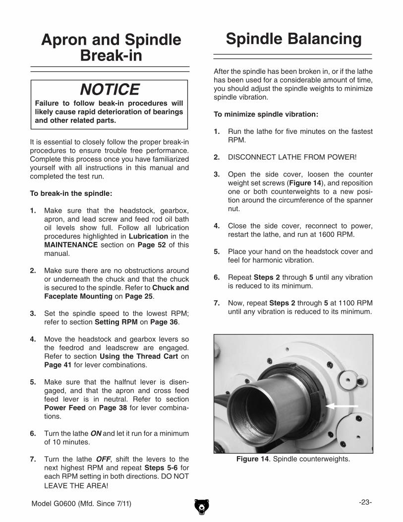
Spindle Balancing
After the spindle has been broken in, or if the lathe has been used for a considerable amount of time, you should adjust the spindle weights to minimize spindle vibration.
To minimize spindle vibration:
1. Run the lathe for five minutes on the fastest RPM.
2. DISCONNECT LATHE FROM POWER!
3. Open the side cover, loosen the counter weight set screws (Figure 14), and reposition one or both counterweights to a new posi-tion around the circumference of the spanner nut.
4. Close the side cover, reconnect to power, restart the lathe, and run at 1600 RPM.
5. Place your hand on the headstock cover and feel for harmonic vibration.
6. Repeat Steps 2 through 5 until any vibration is reduced to its minimum.
7. Now, repeat Steps 2 through 5 at 1100 RPM until any vibration is reduced to its minimum.
Figure 14. Spindle counterweights.

-24- Model G0600 (Mfd. Since 7/11)
Damage to your eyes, lungs, and ears could result from using this machine without proper protective gear. Always wear safety glasses, a respirator, and hearing protection when operating this machine.
Loose hair and cloth-ing could get caught in machinery and cause seri-ous personal injury. Keep loose clothing and long hair away from moving machinery.
Operation Safety
SECTION 4: OPERATIONS
General
The Model G0600 will perform many types of operations that are beyond the scope of this man-ual. Many of these operations can be dangerous or deadly if performed incorrectly.
The instructions in this section are written with the understanding that the operator has the necessary knowledge and skills to operate this machine. If at any time you are experiencing difficulties performing any operation, stop using the machine!
If you are an inexperienced operator, we strongly recommend that you read books, trade articles, or seek training from an experienced lathe opera-tor before performing any unfamiliar operations. Above all, your safety should come first!
Failure to follow test-run and brake-in pro-cedures will likely cause rapid deteriora-tion of bearings and other related parts.
NOTICE

Model G0600 (Mfd. Since 7/11) -25-
Figure 16. Cam and lock marks.
Cam Release Datum Line
Cam Lock Mark
OFF
To remove a chuck or faceplate:
1. DISCONNECT LATHE FROM POWER!
2. Place a piece of plywood across the lathe ways and position it just under the chuck. The board should be at least 8" wide and 10" long.
3. Turn a cam with the chuck key until the cam lock mark aligns with the cam release datum line shown in Figure 16.
Chuck and FaceplateMounting
The Model G0600 is shipped with the 3-jaw chuck installed. This is a scroll-type chuck, meaning that all three jaws move in unison when adjusted.
The 4-jaw chuck, on the other hand, features independent jaws. This chuck is used for square or unevenly-shaped stock.
If either chuck cannot hold your workpiece, the cast-iron faceplate has slots for T-bolts that hold standard or custom clamping hardware. With the correct clamping hardware, this faceplate will hold non-cylindrical parts such as castings.
The chucks and faceplate have a D-8 Camlock mount. Please note that there are lines stamped into the cam and on the chuck body. A chuck key is used to turn the locking cams (Figure 16) to secure/unsecure the chuck/faceplate.
4. Unlock the other cams in the same manner. Make sure to support the chuck as you align the last cam. The chuck may come off at this point, so it is important that the weight is supported by an adequate chuck cradle.
5. Remove the chuck key.
—If the chuck is still tight on the spindle, tap the back of the chuck with a rubber or wood mallet while supporting the bottom of the chuck.
—If the chuck does not immediately come off, rotate the spindle approximately 60˚ and tap again. Make sure all the marks on the cams and spindle are in proper alignment.
The chuck is heavy and is awkward to han-dle. Always protect the ways when remov-ing or installing a chuck, and make sure that you make a support cradle (Figure 15), lifting hoist, or that you have an assis-tant when installing or removing chucks. Ignoring this warning may lead to a severe crushing or amputation injury!
Figure 15. Wooden chuck support cradle.
-26- Model G0600 (Mfd. Since 7/11)
To install a chuck or faceplate:
1. DISCONNECT LATHE FROM POWER!
2. Place a piece of plywood across the lathe ways and position it just under the chuck.
3. With the help of a hoist or with an assistant, place the chuck on the cradle.
Note: If installing the 4-jaw chuck, use the provided lifting eye (Figure 17) to attach a lifting cable or chain.
Figure 17. Lifting eye.
4. Make sure the chuck taper and spindle taper mating surfaces are perfectly clean.
5. Inspect and make sure that all camlock studs are undamaged, are clean and lightly oiled, and that the camlock stud cap screws are in place and snug.
Figure 18. Cam and lock marks.
Cam Release Datum Line
Cam Lock Mark
6. Align the chuck-to-spindle timing marks (Figure 19), and slide the chuck onto the spindle.
7. Turn a camlock with the chuck key until the cam line falls between the "V" marks Figure 18.
NOTICENever install a chuck or faceplate without having the camlock cap screws in place or fully tightened. If you ignore this notice, once installed the chuck may never be able to be removed since the camlock studs will turn with the camlocks and never release.
8. Lock the other cams in a star pattern so the chuck is drawn up evenly on all sides without any chance of misalignment.
Note: If any of the cam lock marks (Figure 18) do not fall between the "V" marks when the cam lock is tight, you must adjust the offend-ing camlock stud as discussed in Camlock Stud Adjustment on Page 27.
9. Remove the chuck key.
OFF
V's

Model G0600 (Mfd. Since 7/11) -27-
Camlock Stud Adjustment
When fitting a chuck or face plate with camlock studs, or when mounting a new chuck or face-plate, it may be necessary to adjust the camlock studs.
In order to properly install or adjust one or more camlock studs, you must remove a stud locking cap screw, then thread the camlock stud in or out until the line on the side of the stud is flush with the top of the chuck casting (Figure 19). This is an initial adjustment.
When you place the chuck onto the lathe spindle, you may find that one or more camlocks do not fully point between the "V" marks on the chuck.
INCORRECT CORRECT
Between Arrows
Turn Stud In One Turn
INCORRECT
Turn Stud Out One Turn
CamRelease Datum
Camlock Stud
Camlock Cap Screw is Tight But Camlock Stud Can Still Rotate Back and Forth Slightly
Initial Adjustment: Camlock Stud
Alignment Groove is Flush with Chuck
Surface
CHUCK
Chuck-to-Spindle Timing Mark
Figure 19. Camlock stud alignment.
If this is the case, you will have to remove the chuck and fine-tune the camlock stud adjustment. See Figure 19 for which direction to turn the camlock studs.
Once you have adjusted the camlock studs, install the chuck or faceplate as outlined in "To install chuck or faceplate" on Page 26.
NOTICENever install a chuck or faceplate without having the camlock cap screws in place or fully tightened. If you ignore this notice, the chuck may never be able to be removed since the camlock studs will turn with the camlocks and never release.

-28- Model G0600 (Mfd. Since 7/11)
Figure 23. Reversing jaw step 4.
Figure 22. Reversing jaw step 3.
Figure 21. Reversing jaw step 2.
3. Repeat these steps for the other two jaws.
Reversing Jaws
To reverse the jaws:
1. DISCONNECT LATHE FROM POWER!
2. Unbolt, then flip the jaw as shown in Figures 20-23, then re-tighten.
Figure 20. Reversing jaw step 1.

Model G0600 (Mfd. Since 7/11) -29-
Gap Removal
Your lathe has a gap section below the spindle that can be removed for turning large diameter parts. This gap was installed, then ground at the factory during lathe assembly for precise fit and alignment. Factors during the remaining assem-bly apply additional forces to the gap; therefore, replacing the gap to the original position will be very difficult. We don't recommend removing the gap. Reinstallation to exact factory align-ment is nearly impossible. The only option is to then leave the gap out.
To remove the gap:
1. Remove four cap screws from the bottom of the gap and two from the ends of the ways (see Figure 24).
2. Remove the set screw plug, and assemble an M6-1 x 30 cap screw, 6mm flat washer, and the gap pin puller hub shown in Figure 24.
3. Thread the cap screw into the threaded hole and tighten until the pin is pulled free of the gap and bed.
4. Repeat on the remaining pin.
5. Tap the outside of the gap with a dead blow hammer to loosen, and remove the gap sec-tion.
Tailstock
The tailstock (Figure 25) of the Model G0600 lathe can be used to support workpieces with the use of a live or dead center. It can drill or bore holes in the center of a part, using a drill bit and chuck, or MT#5 tapered shank drill bit. The tailstock can also be used for cutting shallow tapers by using the offset adjustment.
To use the tailstock:
1. Pull up on the lock handle.
2. Slide the tailstock to the desired position.
3. Push the tailstock lock handle to lock the tailstock in place.
To use the tailstock quill:
1. With the tailstock locked, pull up on the quill lock lever to unlock.
2. Turn the quill feed handle clockwise to feed/move the quill towards the spindle, or turn counterclockwise to move the quill away from the spindle.
3. Push the quill lock lever down to lock the quill in place.
Figure 25. Tailstock and quill lock handles in locked position.
Tailstock Lock
Quill Lock
Quill Feed
Figure 24. Lathe gap and pin puller setup.
Bed and Way Cap Screws

-30- Model G0600 (Mfd. Since 7/11)
10. Turn another 0.010" off of the diameter and check for a taper. Repeat until the desired amount of accuracy is achieved.
Looking down from above.
Move tailstock toward back of lathe 1/2 the
amount of taper.
Figure 28. Tailstock adjustment option #2.
Move tailstock toward front of lathe 1/2 the
amount of taper.
Looking down from above.
Figure 27. Tailstock adjustment option #1.
Figure 26. Chuck centering the dead center.
Aligning Tailstock
To align the tailstock:
1. Using a precision level, make sure the bedways are level side-to-side and front-to-back. If the lathe is not level, shim the lathe base as required before proceeding.
2. Get two pieces of steel round stock that are 2" diameter x 6" inches long.
3. Center drill both ends of one piece of the round stock. Set the round stock aside for use in Step 6.
4. Using the other piece of stock, make a dead center by turning a shoulder to make a shank. Flip the piece over in the chuck and turn a 60º point (Figure 26).
Note: As long as the dead center remains in
the chuck, the point of your center will remain true to the spindle axis. But remember the point will have to be refinished whenever it is removed and returned to the chuck.
5. Place the live center in the tailstock.
6. Attach a lathe dog to the round stock and mount it between the centers.
7. Turn approximately 0.010" off the diameter.
8. Mount a dial indicator so the plunger is on the tailstock barrel before moving the tailstock.
9. Measure the stock diameter with a microm-eter.
— If the diameter is thicker at the tailstock end, move the tailstock toward you half of the diameter (Figures 27).
— If the diameter is thinner at the tailstock end, move the tailstock away from you half the distance of the diameter (Figure 28).

Model G0600 (Mfd. Since 7/11) -31-
Drilling with Tailstock
Figure 29. Typical tailstock chuck installation.
Figure 30. Typical tailstock tapered drill bit installation.
To install the tapered drill chuck:
1. With the tailstock locked, pull up to unlock the quill lock lever.
2. Turn the quill feed handle clockwise to extend the quill about one inch.
3. Insert a tapered drill arbor (Figure 29), or the tapered drill shank (Figure 30), into the quill until the taper is firmly seated. The matching tapers hold the arbor.
4. Turn the quill feed handle clockwise to feed the drill bit into the rotating workpiece.
5. To remove the chuck taper, turn the quill feed handle counterclockwise until the chuck is pushed out from the tailstock taper.
Cutting Tapers with Tailstock
The tailstock can be offset to cut a taper.
To offset the tailstock:
1. Lock the tailstock in position, and loosen the jack screw located just above the adjustment screw (Figures 31 and 32).
2. When the offset is achieved, snug the jack screw that you have been turning counter-clockwise, and then snug opposite jack-screw.
Figure 31. Tailstock off-set adjustments.
Left Side Jack Screw
Scale
Turn CCW
Turn CCW
Turn CW
Turn CW
Figure 32. Jack screw adjustment verses tailstock movement.

-32- Model G0600 (Mfd. Since 7/11)
Centers
The dead center is used in the tailstock to support workpieces. When used in the tailstock, make sure to keep the dead center tip and workpiece lubricated.
This lathe is supplied with two MT#5 dead cen-ters–one is HSS and one is carbide tipped. The supplied MT#5-#7 sleeve fits into the spindle taper to hold the MT#7 center.
To install a dead or live center:
1. Feed the quill out about 1" so that the dead center can be inserted.
2. Insert the dead center into the quill opening. Matching tapers provide the locking action (see Figure 33).
Figure 33. Inserting dead center.
Figure 34. Typical faceplate and dead center setup.
NOTICEFailure to keep dead center point well lubricated will damage dead center and workpiece.
The dead center can also be used in the spindle. The most common application is when using the faceplate (see Figure 34).
To install the dead center in the spindle:
1. Remove the chuck from the spindle.
2. Install the dead center in the spindle sleeve.
3. Install the sleeve and center into the spindle opening.
4. Attach the faceplate to the spindle.
Note: When using the dead center in the spindle, use a lathe dog so that your part will rotate with the spindle and not spin on the dead center tip.
3. Move the tailstock into position and lock in place with the tailstock lock lever.
4. Feed the quill into the workpiece.
Note: Make sure there is a center drilled hole in the end of workpiece for the dead center.
5. Lock the quill into place once the live center and the part rotate together. The quill may need to be adjusted during operation.
6. To remove the dead center, retract the quill until the dead center pops free.

Model G0600 (Mfd. Since 7/11) -33-
Figure 35. Steady rest adjustments.
Thumb Knobs
Steady RestThe steady rest serves as a support for long shafts (length to diameter ratio of 3:1 or greater). The steady rest can be placed anywhere along the length of the workpiece.
To install/use the steady rest:
1. With a helper, carefully place the steady rest on the lathe bedways so the triangular notch fits over the angled portion of the rear bedway.
2. Loosen the three thumb knobs so the finger positions can be adjusted (see Figure 35).
Figure 36. Hand lock knob.
HandLockKnob
4. Position the steady rest where desired. Tighten the hex nut at the base of the steady rest to secure it in place.
5. Close the steady rest so that the workpiece is inside the fingers and tighten the hand knob.
6. Set fingers snug to the workpiece and secure by tightening the three thumb knobs. Fingers should be snug and allow rotational move-ment of the workpiece. Lubricate the finger bearings with oil during operation.
3. Loosen the hand lock knob and open the steady rest so a workpiece can fit inside of the fingers (see Figure 36).
Hand Knob
Finger

-34- Model G0600 (Mfd. Since 7/11)
Follow Rest
The follow rest in Figure 37 is mounted on the saddle and follows the movement of the tool. The follow rest requires only two fingers as the cut-ting tool acts as the third. The follow rest is used on long, slender parts to prevent flexing of the workpiece from the pressure of the cutting tool. It should be used when the workpiece length to diameter ratio is 3:1 or greater.
The sliding fingers are set similar to those of the steady rest—free of play but not binding. Always lubricate during operation. Remove the follow rest from the saddle when not in use. After prolonged use, the fingers will need to be milled or filed to cleanup the contact surface.
Figure 37. Follow rest attachment.
Setting Compound Slide
2. Rotate the compound slide to the desired angular position. Use the scale at the base of the slide and the indicator marks on the carriage to set the position.
3. Tighten the two cap screws. Be sure to not overtighten, as you may strip threads.
Note: It is nessary to install your 60° degree tool bit and set it and the compound rest so it is perfectly perpendicular to a workpiece. Then using a protractor offset the compound rest to 29.5° degrees and mark the location on the cross slide. You will then have a quick refrence point for setting the ofset angle for cutting threads.
Figure 38. Compound slide set at an angle.
Cap Screw
Compound Slide
The compound slide is used to cut tapers on parts or to set the proper infeed angle when threading. It may also be used to cut specific lengths longitu-dinally, when set parallel to the spindle axis.
The compound slide handwheel has a graduated dial for precise inch feed increments. The base of the compound slide has a graduated scale for angular setup.
To set the angular position:
1. Loosen the two cap screws, one on each side of the compound slide (see Figure 38).

Model G0600 (Mfd. Since 7/11) -35-
Quick ChangeTool Post
This 500 series quick change tool post allows for speedy tool changes. Tool registration and index-ing is also fast and easy with the knurled jack screw assembly. The tool post is precision ground and hardened. The internal mechanism is a piston type design that locks the tool holder in place with superior rigidity (Figure 39).
Figure 39. Tool holder and tool post.
Foot Brake
The Model G0600 lathe comes equipped with a foot brake (see Figure 40). The foot brake is intended to be used primarily as a time saving tool. The best method for using the foot brake is turn the spindle lever OFF, then step on the foot brake partially to stop the spindle.
Fully pushing the footbrake while the spindle is ON will kill the power to the motor and bring the spindle to a stop. Stopping the spindle in this manner is harder on the lathe gearbox, brake pad, and belts. This type of brake application should be reserved for panic situations. Once stopped, the spindle lever will then need to be returned to the neutral position.
Note: Do not confuse this feature with the emer-gency stop button. The emergency stop button cuts power to the machine and does not apply the brake. This button must be reset to restore power to the lathe.
Figure 40. Foot brake and spindle ON/OFF lever.
Foot Brake
Spindle ON/OFF Lever
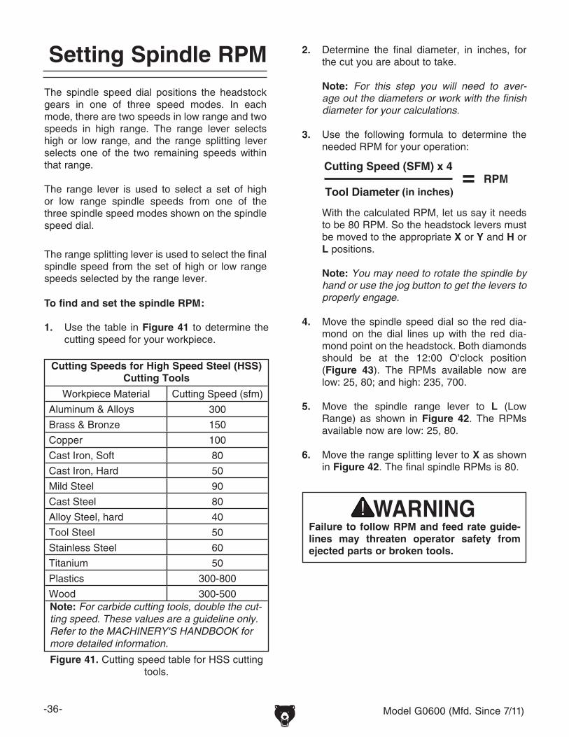
-36- Model G0600 (Mfd. Since 7/11)
2. Determine the final diameter, in inches, for the cut you are about to take.
Note: For this step you will need to aver-age out the diameters or work with the finish diameter for your calculations.
3. Use the following formula to determine the needed RPM for your operation:
With the calculated RPM, let us say it needs to be 80 RPM. So the headstock levers must be moved to the appropriate X or Y and H or L positions.
Note: You may need to rotate the spindle by hand or use the jog button to get the levers to properly engage.
4. Move the spindle speed dial so the red dia-mond on the dial lines up with the red dia-mond point on the headstock. Both diamonds should be at the 12:00 O'clock position (Figure 43). The RPMs available now are low: 25, 80; and high: 235, 700.
5. Move the spindle range lever to L (Low Range) as shown in Figure 42. The RPMs available now are low: 25, 80.
6. Move the range splitting lever to X as shown
in Figure 42. The final spindle RPMs is 80.
Setting Spindle RPM
To find and set the spindle RPM:
1. Use the table in Figure 41 to determine the cutting speed for your workpiece.
Cutting Speeds for High Speed Steel (HSS) Cutting Tools
Workpiece Material Cutting Speed (sfm)
Aluminum & Alloys 300
Brass & Bronze 150
Copper 100
Cast Iron, Soft 80
Cast Iron, Hard 50
Mild Steel 90
Cast Steel 80
Alloy Steel, hard 40
Tool Steel 50
Stainless Steel 60
Titanium 50
Plastics 300-800
Wood 300-500Note: For carbide cutting tools, double the cut-ting speed. These values are a guideline only. Refer to the MACHINERY'S HANDBOOK for more detailed information.
Figure 41. Cutting speed table for HSS cutting tools.
Failure to follow RPM and feed rate guide-lines may threaten operator safety from ejected parts or broken tools.
The spindle speed dial positions the headstock gears in one of three speed modes. In each mode, there are two speeds in low range and two speeds in high range. The range lever selects high or low range, and the range splitting lever selects one of the two remaining speeds within that range.
The range lever is used to select a set of high or low range spindle speeds from one of the three spindle speed modes shown on the spindle speed dial.
The range splitting lever is used to select the final spindle speed from the set of high or low range speeds selected by the range lever.

Model G0600 (Mfd. Since 7/11) -37-
Figure 42. Range levers.
Figure 44. Spindle speed lever in central position—55, 170, 525,1600 RPMs available.
Figure 45. Spindle speed lever in right position —35, 120, 350,1100 RPMs available.
Figure 43. Spindle speed lever in left position.
X + L = 80 RPM

-38- Model G0600 (Mfd. Since 7/11)
For either cross or longitudinal feed, move the power feed lever on the apron in the directions indicated by the placard (Figure 47), and then move the feed direction lever (Figure 48) to select feed direction. Remember, all directions reverse when spindle rotation is reversed. Refer to the Using the Thread Chart on Page 41 to learn how to shift the lathe in order to get a specific feed rate.
Power Feed
NOTICEFeed rate is based on spindle RPM. High feed rates combined with high spindle speeds result in a rapidly moving carriage or cross slide. Pay close attention to the feed rate you have chosen and keep your hand poised over the ON/OFF switch. Failure to take this precaution can lead to carriage and chuck crash.
Figure 47. Power feed lever positions.
Longitudinal Feed
Cross Feed
Neutral
Figure 48. Feed direction lever.
Manual Feed
You can manually move the cutting tool around the lathe by three methods. This section will review the individual controls on the carriage and provide descriptions of their uses (see Figure 46).
Figure 46. Carriage Controls.
Cross slide Handwheel
Longitudinal Handwheel
Compound Slide
Handwheel
Longitudinal HandwheelThe longitudinal handwheel moves the carriage left or right along the bed. This control is help-ful when setting up the machine for turning or when manual movement is desired during turning operations.
Cross Slide HandwheelThe cross slide handwheel moves the top slide toward and away from the work. Turning the dial clockwise moves the slide toward the workpiece. The graduated dial can be adjusted by holding the handwheel with one hand and turning the dial with the other.
Compound Slide HandwheelThe compound slide handwheel controls the posi-tion of the cutting tool relative to the workpiece. The compound slide is adjustable for any angle within its range. The graduated dial is adjustable using the same method as the dial on the cross slide. Angle adjustment is secured by cap screws on the base of the compound slide.

Model G0600 (Mfd. Since 7/11) -39-
Four-Position Apron Stop
Use the four-position apron stop for disengaging the apron automatically at up to four different apron locations.
You can tighten the eccentrics in place on the rod, each at different rotated positions, so each eccentric corresponds with a number on the dial. Then, depending which number you turn the stop selection dial (Figure 49) to, the rod will align the toe of the stop eccentric where you want the apron to stop. When the apron reaches that point, the crown of the stop eccentric will depress the clutch release lever and disengage the apron from the feed rod, thus stopping the apron.
Figure 49. Four-position apron stop.
StopEccentric
Clutch Release
Stop Selection Dial
Apron
This four-position apron stop system is only made to disengage the apron from the feed rod. When the lead screw is engaged for threading operations, the four-position apron stop will not disengage the apron—you must manually disengage the apron from the feed rod with the half nut lever or the apron will crash into the chuck.
NOTICE
Every time you readjust the stop eccen-trics, always manually test your apron stop setting before you rely on apron stop sys-tem to automatically disengage the apron.
NOTICE

-40- Model G0600 (Mfd. Since 7/11)
Starting Lathe
Starting and stopping the lathe requires a couple of steps. First, the master switch (Figure 50) on the back of the lathe must be turned to the "1" position "ON", the green power lamp (Figure 51) will light.
Figure 50. Master switch.
Figure 51. Power light.
Power Lamp
Emergency Stop
Move the spindle ON/OFF lever (Figure 52) to start and stop spindle and chuck rotation.
Figure 53. Foot brake.
Foot Brake
Figure 52. Spindle ON/OFF Lever.
Spindle ON/OFF Lever
To slow a free wheeling chuck to a stop without cutting power to the motor, partially press the foot brake (Figure 53) down. To stop the chuck and kill all power to the motor and controls as fast as possible in an emergency situation, push the brake down completely. Once stopped, the spindle lever will then need to be returned to the neutral position.
Note: If you press the emergency stop button now, the power light will go out and cut power to the motor and spindle ON/OFF lever. Twisting the emergency stop button and letting it pop out will restore power for all lathe operations.

Model G0600 (Mfd. Since 7/11) -41-
This lathe comes with one 48-tooth and two 57-tooth change gears installed for cutting inch or metric threads. For cutting dimetrial or modu-lar pitch threads, certain gears must be replaced and repositioned (refer to Dimetrial and Modular Pitch Threading on Page 42).
Example: To cut a modular pitch thread of 0.5, the threading chart in Figure 56 indicates that you must change the gears into the (W) mode shown, and move the levers and dials to positions I, C, F, S, and 4 (Figures 54 and 55).
To cut inch and metric threads, or to use the chart for the X and Y power feed rates, the change gears must be changed to the (V) mode. Refer to Inch and Metric Pitch Threading on Page 44.
Using the Thread Chart
Figure 56. Threading chart.Figure 55. Gearbox controls.
Figure 54. Headstock controls.
48
57
57
5766
42
48
0.5Modular
Pitch Thread is Achieved
-42- Model G0600 (Mfd. Since 7/11)
3. Put on your safety glasses, and using a 14mm wrench, remove the center spindle and gear assembly (Figure 58).
Dimetrial and Modular Pitch Threading
5. Use a press to remove and flip the direction of the spindle, then install the retaining ring.
Note: You must use a press and a collar that will support the inner bearing race when removing the spindle from the gear. Do not use a hammer and punch to drive the spindle from the gear assembly or you will damage the ball bearings.
Note: When finished, and installed back on the lathe, the spindle must hold the 66-tooth gear outward as shown in (Figure 63).
6. Place the bore of the 66-tooth gear onto the shoulder of the 57-tooth gear, and align the three bolt holes (Figure 58) of the gears.
Figure 59. Spindle and center gear assy.
4. Using retaining ring pliers, remove the retain-ing ring from the spindle (Figure 59).
Figure 58. Center spindle, 57-tooth gear, and 66-tooth gear.
Bolt Hole
57-Tooth
66-Tooth
Shoulder
Spindle
Spindle
66-Tooth
57-Tooth
Center Race
Retaining Ring
This lathe comes with one 48-Tooth and two 57-Tooth change gears installed for cutting inch or metric threads. However for cutting dimetrial or modular threads the lower 57-Tooth gear must be replaced with the included 42-Tooth gear, and the 66-Tooth gear must be installed onto the shoulder of the center 57-Tooth gear (Figure 57). Gear positions must also be changed.
To setup the lathe to cut dimetrial or modular pitch threads:
1. DISCONNECT MACHINE FROM POWER!
2. Open the side cover and familiarize your-self with the orientation of the change gears (Figure 57).
NOTICESome threading operations may damage the lead screw if performed at high speeds. Always use the slowest speed possible for your particular operation!
Figure 57. Change gear setup for inch and metric thread cutting.
57-Tooth GearCenter Spindle
57-Tooth Gear(Lower Spindle)
48-Tooth Gear(Upper Spindle)
Adjustment Arm
Locknut
Model G0600 (Mfd. Since 7/11) -43-
7. Thread the three M6-1 x 25 cap screws into the gears so the cap screws act as guide dowels allowing the gears to slide together without binding. Do not use a hammer to seat the gear.
8. Press the two gears together and tighten the three cap screws (Figure 59).
9. Remove the 57-tooth gear (Figure 57).
10. Slide the 42-tooth gear onto the lower spindle, install the shoulder washer on the spindle so the shoulder faces the gear (Figure 60), and install the cap screw.
Figure 60. Shoulder washer positioning.
Figure 61. Upper spindle gear positioning.
Shoulder
Shoulder
13. Using a 24mm wrench, loosen the adjust-ment arm locknut (Figure 62), and let the adjustment arm swing away.
11. Using the 6mm hex wrench, remove the upper spindle cap screw, spacer washer, the 48-tooth gear, and the spacer (Figure 57).
12. With the shoulder of the 48-toothed gear facing the bearing seal (Figure 61), slide the gear back onto the shaft, then install the spacer, spacer washer and cap screw.
14. Install the center gear and spindle onto the adjustment arm, then finger tighten the spin-dle.
15. Move the center gear and adjustment arm assembly, then tighten the spindle and adjust-ment arm lock nut so all gears mesh and have 0.0015" to 0.004" of backlash.
16. Rotate the gears by hand to make sure no binding occurs, and then paint the gear teeth with general purpose automotive grease.
17. When you are finished, make sure the gear arrangement matches the (W) mode arrange-ment shown in Figure 56.
18. Close the side cover and refer to the Threading Chart on Page 41 for how to shift your lathe to the appropriate feed or thread pitch.
Seal
Figure 62. Center gear adjustment arm.
Center Spindle
Adjustment Arm and Locknut
Center Gear
Assembly

-44- Model G0600 (Mfd. Since 7/11)
Inch and Metric Pitch Threading
3. Put on your safety glasses, and using a 14mm wrench, remove the center spindle and gear assembly (Figure 63).
4. Using retaining ring pliers, remove the retain-ing ring from the spindle (Figure 64).
5. Use a press to remove and flip the direction of the spindle and reinstall the retaining ring.
Note: You must use a press and a collar that will support the inner bearing race when removing the spindle from the gear. Do not use a hammer and punch to drive the spindle from the gear assembly or you will damage the ball bearings.
Figure 64. Spindle and center gear assy.
Spindle
Center Race
66-Tooth
57-Tooth
Retaining Ring
Cap Screw
If the lathe has been previously setup to cut dimetrial or modular pitch threads, you must rein-stall the 57-Tooth gear on the lower spindle and remove the 66-Tooth gear on the middle spindle, and change certain gear positions.
To setup the lathe to cut inch and metric pitch threads:
1. DISCONNECT MACHINE FROM POWER!
2. Open the side cover and familiarize your-self with the orientation of the change gears (Figure 63).
NOTICEAlways use the slowest speed possible for threading, and avoid deep cuts or you may not be able to disengage the half nut to prvent an apron crash!
Figure 63. Change gear setup for dimetrial and modular thread cutting.
6. Remove the three M6-1 x 25 cap screws that hold the two gears together.
7. Protect the spindle and clamp it in a vise.
8. Carefully, using two #3 flat tip screwdriv-ers inserted between the gears at opposing directions, work the 66-tooth gear off of the shoulder of the 57-tooth gear. Do not use a hammer to separate the gears.
9. Use the 6mm hex wrench and remove the lower spindle cap screw, shoulder washer, and the 42-tooth gear (Figure 63).
57-Tooth Gear(Lower Spindle)
48-Tooth Gear
(Upper Spindle)
Adjustment Arm
Locknut
57-Tooth Gear
(Center Spindle)
66-Tooth Gear
(Center Spindle)

Model G0600 (Mfd. Since 7/11) -45-
Figure 65. Shoulder washer positioning.
Shoulder
10. Slide the 57-tooth gear onto the lower spindle, install the shoulder washer on the spindle so the shoulder faces the gear (Figure 65), and install the cap screw.
11. Using the 6mm hex wrench, remove the upper spindle cap screw, spacer washer, the 48-tooth gear, and the spacer (Figure 63).
12. Slide the spacer onto the spindle, then the 48-toothed gear with the shoulder facing the spacer (Figure 66). Install the spacer wash-er, and secure with the cap screw.
13. Using a 24mm wrench, loosen the adjust-ment arm locknut (Figure 67), and let the adjustment arm swing away.
Figure 67. Center gear adjustment arm.
14. Install the center gear and spindle onto the adjustment arm, then finger tighten the spin-dle.
15. Move the center gear and adjustment arm assembly, then tighten the spindle and adjust-ment arm lock nut so all gears mesh and have 0.0015" to 0.004" of backlash.
16. Rotate the gears by hand to make sure no binding occurs, and then paint the gear teeth with general purpose automotive grease.
17. When you are finished, make sure the gear arrangement matches the (V) mode arrange-ment shown in Figure 56.
18. Close the side cover and refer to the Threading Chart on Page 41 for how to shift your lathe to the appropriate feed or thread pitch.
Adjustment Arm Locknut
Center Gear Assembly
Spindle
Adjustment Arm
Figure 66. Upper spindle gear and spacer positioning.
Shoulder Spacer
-46- Model G0600 (Mfd. Since 7/11)
For fractional TPI and 23 TPI: Numbers 2 or 4, 1 or 3, or any two opposing marks can be used.
For 3, 5, 7, 9, 11, 19, 27 odd TPI and even 26 TPI: Any four grouped numbers or marks can be used.
For all other even numbered TPI: Any number or mark can be used. Note: Since the leadscrew is a 4 TPI, then the thread dial is not needed for any thread that is divisible by 4.
Number of teeth on the thread dial drive gear.
Thread DialThis lathe is equipped with a thread dial that lets you know where on the leadscrew you can re-engage the halfnut to resume inch threading. However, since the leadscrew is a 4 TPI, then the thread dial is not needed for any thread that is divisible by 4. Refer to the Indicator Table in Figure 68 and see Figure 69 for dial locations.
For metric dimetrial and modular threading, the thread dial is not used and you must leave the halfnut lever engaged until the threading job is complete.
Figure 69. Thread dial use.
Figure 68. Indicator Chart.
NOTICEAlways use the slowest speed possible for threading, and avoid deep cuts or you may not be able to disengage the half nut to pre-vent an apron crash!

Model G0600 (Mfd. Since 7/11) -47-
SECTION 5: ACCESSORIESACCESSORIES
This section includes the most common accessories available for this lathe through the Grizzly catalog, online at www.grizzly.com, or by calling 1-800-523-4777.
Figure 70. G7895 Citrus Degreaser.
G7895—Citrus DegreaserThis citrus based degreaser is perfect for cleaning cosmolene off of new equipment. It also works for cleaning auto parts, tools, concrete, and porcelain surfaces. Natural, safe for the environment, and contains no CFC’s.
Figure 72. Boeshield® T-9 spray.
G2871—Boeshield® T-9 12 oz SprayG2870—Boeshield® T-9 4 oz SprayThis ozone friendly protective spray penetrates deep and really holds up against corrosive envi-ronments. Lubricates metals for months and is safe for use on most paints, plastics, and vinyls.
Figure 73. G96® Gun Treatment spray.
H3788—G96® Gun Treatment 12 oz SprayH3789—G96® Gun Treatment 4.5 oz SprayThis triple action gun treatment cleans, lubricates, and protects all metal parts. Contains solvents that completely remove all traces of rust and cor-rosion and leaves no gummy residue.
Figure 71. Eye protection assortment.
Basic Eye ProtectionT20501—Face Shield Crown Protector 4"T20502—Face Shield Crown Protector 7"T20503—Face Shield WindowT20451—“Kirova” Clear Safety GlassesT20452—“Kirova” Anti-Reflective S. GlassesH7194—Bifocal Safety Glasses 1.5H7195—Bifocal Safety Glasses 2.0H7196—Bifocal Safety Glasses 2.5
T20451
T20452
T20502
T20503
H7194
-48- Model G0600 (Mfd. Since 7/11)
G1238—Precision 5-C Collet SetThis 15 piece 5-C collet set is made from high grade collet steel and precision ground to exact-ing tolerances.
Figure 74. H7938 Quick Change Collet Closer.
H7938—Quick Change Collet CloserThis Quick Change Collet Closer allows you to quickly interchange parts on your Model G0600 Metal-Cutting Lathe. The positive-locking handle clamps standard 5-C collets safely and securely for precision turning.
See the current Grizzly catalog for a full line of 5-C collets.
Figure 75. H9737 Taper Attachment.
H9737—Taper Attachment for the G0600 Lathe.The Model H7937 mounts to the back of the car-riage and bed way to produce accurate tapers without repositioning.
H3741—30 HP/25 HP Start, Phase ConverterAdd 3-phase electrical supply with this rota-ry phase converter! Operate single or multiple motors, transformers, and resistance loads at 100% power and 95% efficiency while saving big dollars at cheaply metered, single-phase electri-cal rates. For application assistance, please call our technical support group at (570) 546-9663.
Figure 77. Rotary Phase Converter
Figure 76. 15 Piece 5-C Collet Set.

Model G0600 (Mfd. Since 7/11) -49-
H2670—HSS Square Tool Bits ½" x ½" x 4Our ground tool bits are M-2 HSS, making them some of the most durable tool bits around. Make your own specialized cutters in any shape using a silicon carbide grinding wheel (G8235-37) on your grinder.
Figure 78. H2670 HSS Square Tool Bits.
Figure 79. H5687 Pre-Ground Tool Bit Set.
H5687—8-Pc. Pre-Ground Tool Bit SetTired of grinding your blank high speed steel tool bits? We've done it for you! 8-pc set comes with these sharpened profiles: offset right and left hand tools with chip breaker, straight and chip breaker style threading tools, internal threading tool, part-ing tool, boring tool and turning tool. These tool bits are evenly hardened to better than 64C.
G9777—20-Pc. Carbide Tipped Tool Bit SetAn exceptional value for carbide lathe tool bits! This twenty-piece set offers tremendous savings over bits sold individually, plus every type is dupli-cated and ready at hand when you need it. The carbide is C-6 grade for cutting steel and alloys.
Figure 80. G9777 20 Pc. Carbide Tool Set.
Figure 81. G5640 5 Pc. Indexable Tool Set.
G5640—5-Pc. Indexable Carbide Tool Set ½"G6706—Replacement TiN Coated Carbide Indexable InsertFive-piece turning tool set features indexable car-bide inserts with "spline" type hold-down screw that allow indexing without removing the screw. Each set includes AR, AL, BR, BL, and E style tools with carbide inserts, hex wrench, extra hold-down screws and a wooden case.

-50- Model G0600 (Mfd. Since 7/11)
H5930—HSS Center Drill Set 60°H5931—HSS Center Drill Set 82°Double ended HSS center drills, are precision ground for unsurpassed accuracy. Each set includes sizes 1-4.
Figure 82. HSS Center Drills.
H6499—Brass 5-C Emergency ColletH6500—Nylon 5-C Emergency ColletH7500—Steel 5-C Emergency ColletEmergency collets to the rescue! We offer three styles of collets to get you out of a bind and back to work! Available in steel, brass and nylon, our 5-C collets are easy to machine to the size you need for holding delicate parts, odd sized tooling or your greatest challenge. (The steel collets have annealed faces and bores.) Minimum diameters are less than 0.085". Every busy shop should have a few of these on hand.
Figure 83. 5-C Emergency Collets
H6499
H6500
H7500
H7504—6 Pc. Square 5-C Collet Set H7505—7 Pc. Hex 5-C Collet SetWhether you’re using a spin indexer, collet closer on a lathe or grinding fixture on your surface grind-er, eventually you are going to need to hold hex or square stock. These two sets feature hardened and ground bodies and sizes that fit most needs. The H7504 square set has sizes: 1⁄8", 1⁄4", 3⁄8", 1⁄2", 5⁄8" and 3⁄4". The H7505 hex collet set has sizes: 1⁄8", 1⁄4", 3⁄8", 1⁄2", 5⁄8", 3⁄4" and 7⁄8".
Figure 85. H2987-91 Lathe Dogs.
H2987—½" Bent Lathe DogH2988—1" Bent Lathe DogH2989—1½" Bent Lathe DogH2990—2" Bent Lathe DogH2991—3" Bent Lathe DogJust the thing for precision machining between centers! These bent tail lathe dogs are made of durable cast iron and feature square head bolts.
Figure 84. 5-C Hex and Square Collets.
H7504 6 PIECE SQUARE
H7505 7 PIECE HEX

Model G0600 (Mfd. Since 7/11) -51-
Figure 86. H4456-63 HSS Ground Center Drills.
Figure 87. G9245 Live Center Set.
MODEL SIZEBODY DIA.
DRILL DIA.
OVERALL LENGTH
H4456 1 1⁄8" 3⁄64" 11⁄4"
H4457 2 3⁄16" 5⁄64" 17⁄8"
H4458 3 1⁄4" 7⁄64" 2"
H4459 4 5⁄16" 1⁄8" 21⁄8"
H4460 5 7⁄16" 3⁄16" 23⁄4"
H4461 6 1⁄2" 7⁄32" 3"
H4462 7 5⁄8" 1⁄4" 31⁄4"
H4463 8 3⁄4" 5⁄16" 31⁄2"
These high speed steel center drills are precision ground for unsurpassed accuracy.
G9245—MT4 Live Center SetA super blend of quality and convenience, this live center set offers seven interchangeable tips. High-quality needle bearings prolong tool life and special tool steel body and tips are precision ground. Supplied in wooden box.

-52- Model G0600 (Mfd. Since 7/11)
Always disconnect power to the machine before performing maintenance. Failure to do this may result in serious person-al injury.
HeadstockThe headstock gearbox is lubricated with an oil pump and 20W non-detergent oil, ISO 68, or an equivalent gear box machine oil. Keep the oil level full as seen in the sight glass shown in (Figure 88). When the lathe is running, periodically make sure that you see oil pumping out of the oil tube in the pump-check sight glass (Figure 88). If oil is not seen pumping, shut the lathe down immedi-ately and contact Grizzly Technical Support.
Lubrication
Cleaning the Model G0600 is relatively easy. Make sure to unplug the lathe before cleaning it. Clean your machine every day or more often as needed. Remove chips as they accumulate. Wet chips left on the machine will eventually invite oxidation and gummy residue to build up around moving parts. Cleaning will help keep your lathe running smoothly. Always be safe and responsible with the use and disposal of cleaning products.
Cleaning
SECTION 6: MAINTENANCE
For optimum performance from your machine, follow this maintenance schedule and refer to any specific instructions given in this section.
Daily Checks and Maintenance:• Loose mounting bolts.• Emergency stop and brake operation.• Worn or damaged wires.• Coolant level.• Lubrication levels.• Remove chips.• Any other unsafe condition.
Monthly Check:• Change coolant as needed.
Schedule
General Lubrication Keep machined metal surfaces like the chuck, ways bores, controls, change gears, rollers, and unpainted cast iron rust-free with applications of products like G96® Gun Treatment, SLIPIT®, or Boeshield® T-9 (see SECTION 5: ACCESSORIES on Page 47 for more details).
Figure 88. Oil pump sight glass.
HeadstockOil Sight
Glass

Model G0600 (Mfd. Since 7/11) -53-
Quick Change GearboxThe quick change gearbox is lubricated with 20W non-detergent oil, ISO 68, or an equivalent gear box machine oil. Keep the oil level full as seen in the sight glass (Figure 91).
After the first month of daily operation, drain and refill the gear box. See Figure 92 for plug loca-tions. Change the gearbox oil yearly, or more frequently if heavy machine use requires it.
After the first month of daily operation, drain the oil through the drain plug at the back of the head-stock (Figure 89), open the side cover and refill the headstock through the fill plug (Figure 90). Change the headstock oil yearly, or more fre-quently if heavy machine use requires it.
Figure 89. Headstock oil drain.
Headstock Oil Drain
Figure 90. Headstock oil fill.
Headstock Oil Fill
Figure 91. Oil sight glass locations.
Gear Box Oil
Sight Glass
Figure 92. Gearbox oil fill.
Gearbox Oil Fill
Gearbox Oil Drain
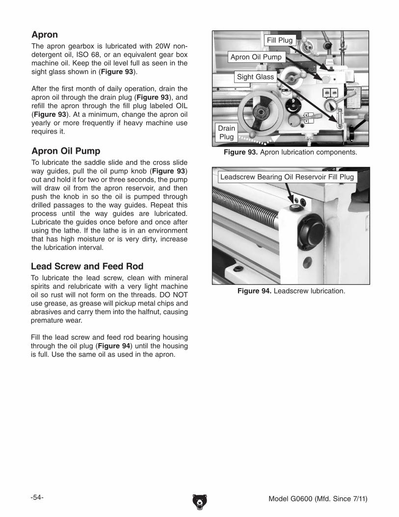
-54- Model G0600 (Mfd. Since 7/11)
ApronThe apron gearbox is lubricated with 20W non-detergent oil, ISO 68, or an equivalent gear box machine oil. Keep the oil level full as seen in the sight glass shown in (Figure 93).
After the first month of daily operation, drain the apron oil through the drain plug (Figure 93), and refill the apron through the fill plug labeled OIL (Figure 93). At a minimum, change the apron oil yearly or more frequently if heavy machine use requires it.
Apron Oil PumpTo lubricate the saddle slide and the cross slide way guides, pull the oil pump knob (Figure 93) out and hold it for two or three seconds, the pump will draw oil from the apron reservoir, and then push the knob in so the oil is pumped through drilled passages to the way guides. Repeat this process until the way guides are lubricated. Lubricate the guides once before and once after using the lathe. If the lathe is in an environment that has high moisture or is very dirty, increase the lubrication interval.
Lead Screw and Feed RodTo lubricate the lead screw, clean with mineral spirits and relubricate with a very light machine oil so rust will not form on the threads. DO NOT use grease, as grease will pickup metal chips and abrasives and carry them into the halfnut, causing premature wear.
Fill the lead screw and feed rod bearing housing through the oil plug (Figure 94) until the housing is full. Use the same oil as used in the apron.
Figure 94. Leadscrew lubrication.
Leadscrew Bearing Oil Reservoir Fill Plug
Figure 93. Apron lubrication components.
Fill Plug
Sight Glass
Apron Oil Pump
DrainPlug

Model G0600 (Mfd. Since 7/11) -55-
Ball Oilers This lathe has 11 ball oiler locations. To lubricate ball oilers, clean the outside of the ball oiler, push the ball with the tip of the oil can nozzle and squirt one or two drops of oil inside the oiler before and after using the lathe. If the shop environment has high moisture or is very dirty, increase the oiling interval. Use the same oil as you are using for the headstock. The locations listed below show the ball oilers in Figures 98 to 97:
Figure 97. Cross slide leadscrew end bearing ball oiler location: 1 ball oiler on the cross slide
lead screw end cap.
Figure 96. Cross slide ball oiler location: 1 ball oiler on the cross slide.
Figure 98. Tailstock ball oiler locations: 1 ball oiler on the tailstock handwheel hub and2 ball oilers on the tailstock housing top.
Figure 95. Apron and slide ball oiler locations: 4 ball oilers on the compound rest, 1 ball oiler
on the cross slide handle hub, 1 ball oiler on the apron feed handle hub.

-56- Model G0600 (Mfd. Since 7/11)
Coolant System
The coolant pump and reservoir are located in the base behind the vented cover on the tailstock end of the lathe.
To perform regular maintenance on the cut-ting fluid system:
1. Remove the access cover at the rear of the lathe (Figure 99).
Figure 99. Coolant pump and reservoir.
2. Pump the old cutting fluid out of the reser-voir and dispose of according to State and Federal Environmental Laws.
3. Using a magnet, brush, and rags clean out metal chips from the bottom of the reservoir. Flush with hot soapy water if required.
4. Refill the reservoir with applicable water-soluble cutting fluid. Closely follow the fluid manufacturer's instructions for mixing.
5. Open the valve on the coolant nozzle.
6. Turn the coolant pump ON (Figure 100) to prime the coolant system and to see if the coolant is cycling properly.
7. Replace the access cover.
BIOLOGICAL AND POISON HAZARD! Use the correct personal protection equipment when handling cutting fluid and by follow federal, state, and fluid manufacturer requirements to properly dispose of cutting fluid.
Figure 100. Coolant pump switch.
Model G0600 (Mfd. Since 7/11) -57-
Review the troubleshooting and procedures in this section to fix your machine if a problem develops. If you need replacement parts or you are unsure of your repair skills, then feel free to call our Technical Support at (570) 546-9663.
SECTION 7: SERVICE
Troubleshooting
Motor & Electrical
Symptom Possible Cause Possible SolutionMachine does not start or a circuit breaker trips.
1. Foot brake is engaged.2. Emergency stop push-button is engaged/
faulty.3. Power supply is at fault/switched OFF.4. Fuse has blown.5. Plug/receptacle is at fault or wired incorrectly.6. Start capacitor is at fault.7. Motor connection wired incorrectly.8. Thermal overload relay has tripped.
9. Contactor not getting energized/has burnt con-tacts.
10. Wall fuse/circuit breaker is blown/tripped.
11. Motor ON button or ON/OFF switch is at fault.12. Wiring is open/has high resistance.
13. Motor is at fault.14. Spindle rotation switch is at fault.15. Foot brake safety switch is faulty.
1. Check to see that foot brake is up.2. Rotate clockwise slightly until it pops out/replace it.
3. Power supply is at fault/switched OFF.4. Correct short/replace fuse in main electrical box.5. Test for good contacts; correct the wiring.6. Test/replace if faulty.7. Correct motor wiring connections.8. Turn cut-out dial to increase working amps and push
the reset pin. Replace if tripped multiple times (weak relay).
9. Test for power on all legs and contactor operation. Replace unit if faulty.
10. Ensure correct size for machine load; replace weak breaker.
11. Replace faulty ON button or ON/OFF switch.12. Check for broken wires or disconnected/corroded
connections, and repair/replace as necessary. 13. Test/repair/replace.14. Turn switch to FWD/REV; replace bad switch.15. Test, replace if needed.
Loud, repetitious noise coming from machine at or near the motor.
1. Pulley setscrews or keys are missing or loose.
2. Motor fan is hitting the cover.
1. Inspect keys and setscrews. Replace or tighten if necessary.
2. Tighten fan or shim cover, or replace items.
Motor overheats. 1. Motor overloaded.2. Air circulation through the motor restricted.
1. Reduce load on motor.2. Clean out motor to provide normal air circulation.
Motor is loud when cutting. Overheats or bogs down in the cut.
1. Excessive depth of cut or feed rate.2. RPM or feed rate wrong for cutting operation.3. Cutting tool is dull.4. Gear setup is too tight, causing them to bind.
1. Decrease depth of cut or feed rate.2. Refer to RPM feed rate chart for appropriate rates.3. Sharpen or replace the cutting tool.4. Readjust the gear setup with a small amount of
backlash so the gears move freely and smoothly when the chuck is rotated by hand.
OFF

-58- Model G0600 (Mfd. Since 7/11)
Symptom Possible Cause Possible SolutionEntire machine vibrates exces-sively upon start-up and while run-ning.
1. Workpiece is unbalanced.
2. Loose or damaged belt(s).3. V-belt pulleys are not properly aligned.4. Worn or broken gear present.5. Chuck or faceplate has become unbalanced.
6. Spindle bearings badly worn.
1. Reinstall workpiece so it is as centered with the spindle bore as possible.
2. Tighten/replace the belt as necessary.3. Align the V-belt pulleys.4. Inspect gears and replace if necessary.5. Rebalance chuck or faceplate; contact a local
machine shop for help.6. Replace spindle bearings.
Bad surface fin-ish.
1. Wrong RPM or feed rate.2. Dull tooling or poor tool selection.
3. Too much play in gibs.4. Tool too high.
1. Adjust for appropriate RPM and feed rate.2. Sharpen tooling or select a better tool for the intend-
ed operation.3. Tighten gibs.4. Lower the tool position.
Can't remove tapered tool from tailstock quill.
1. Quill had not retracted all the way back into the tailstock.
2. Debris was not removed from taper before inserting into quill.
1. Turn the quill handwheel until it forces taper out of quill.
2. Always make sure that taper surfaces are clean.
Cross slide, com-pound slide, or carriage feed has sloppy operation.
1. Gibs are out of adjustment.2. Handwheel is loose.3. a mechanism worn or out of adjustment.
1. Tighten gib screw(s).2. Tighten handwheel fasteners.3. Tighten any loose fasteners on lead screw mecha-
nism.
Cross slide, com-pound slide, or carriage feed handwheel is hard to move.
1. Gibs are loaded up with shavings, dust, or grime.
2. Gib screws are too tight.
3. Backlash setting too tight (cross slide only).
4. Bedways are dry.
1. Remove gibs, clean ways/dovetails, lubricate, and readjust gibs.
2. Loosen gib screw(s) slightly, and lubricate bedways.
3. Slightly loosen backlash setting by loosening the locking screw and adjusting the spanner ring at the end of the handle.
4. Lubricate bedways and handles.
Cutting tool or machine com-ponents vibrate excessively dur-ing cutting.
1. Tool holder not tight enough.2. Cutting tool sticks too far out of tool holder;
lack of support.3. Gibs are out of adjustment.4. Dull cutting tool.5. Incorrect spindle speed or feed rate.
1. Check for debris, clean, and retighten.2. Reinstall cutting tool so no more than 1/3 of the total
length is sticking out of tool holder.3. Tighten gib screws at affected component.4. Replace or resharpen cutting tool.5. Use the recommended spindle speed.
Inaccurate turn-ing results from one end of the workpiece to the other.
1. Headstock and tailstock are not properly aligned with each other.
1. Realign the tailstock to the headstock spindle bore center line.
Chuck jaws won't move or don't move easily.
1. Chips lodged in the jaws. 1. Remove jaws, clean and lubricate chuck threads, and replace jaws.
Carriage won't feed.
1. Gears are not all engaged.2. Gears are broken.3. Loose screw on the feed handle.
1. Adjust gear positions.2. Replace.3. Tighten.
Operation and Work Results

Model G0600 (Mfd. Since 7/11) -59-
Symptom Possible Cause Possible SolutionCarriage hard to move.
1. Carriage lock is tightened down.2. Chips have loaded up on bedways.
3. Bedways are dry and in need of lubrication.4. Longitudinal stops are interfering.
5. Gibs are too tight.
1. Check to make sure the carriage lock bolt is fully released.
2. Frequently clean away chips that load up during turning operations.
3. Lubricate bedways and handles.4. Check to make sure that stops are floating and not
hitting the center stop.5. Loosen gib screw(s) slightly.
Gear change levers will not shift into position.
1. Gears not aligned in headstock. 1. Rotate spindle by hand until gear falls into place.
Loud, repetitious noise coming from machine.
1. Gears not aligned in headstock or no back-lash.
2. Broken gear or bad bearing.3. Workpiece is hitting stationary object.
1. Adjust gears and establish backlash.
2. Replace broken gear or bearing.3. Stop lathe immediately and correct interference
problem.
Tailstock quill will not feed out of tailstock.
1. Quill lock knob is tightened down. 1. Turn knob counterclockwise.
Operation and Work Results

-60- Model G0600 (Mfd. Since 7/11)
Figure 101. Cross slide backlash adjustment socket head cap screws.
Cap Screws
Backlash is the amount of play found in a lead screw. It can be found by turning the cross slide handwheel in one direction, then turning the handwheel the other direction. When the cross slide begins to move, the backlash has been taken up.
Note: Avoid the temptation to overtighten the cross slide backlash screw. Overtightening will cause excessive wear to the sliding block and lead screw. Reducing backlash to less than 0.001" is impractical and reduces cross slide life.
Backlash is adjusted by tightening or loosen-ing the cap screws shown in Figure 101. These screws draw a wedge-type nut against the lead screw and main nut. If you get the gib too tight, loosen the cap screws a few turns, tap the cross slide a few times with a rubber or wooden mallet, and turn the handle slowly back and forth until the handle turns freely. To readjust the backlash, rock the handle back and forth and tighten the screw slowly until the backlash is at approximately 0.001" as indicated on the handwheel dial.
Cross Slide Leadscrew Adjustment
Leadscrew Endplay Adjustment
After a long period of time, you may find that the lead screw for threading operations may develop a bit of end play. This lathe is designed so that play can be removed.
To remove leadscrew end play:
1. DISCONNECT LATHE FROM POWER.
2. Using a 4mm hex wrench, remove the three cap screws and the cover (Figure 102).
3. Using a 3mm hex wrench, loosen the retainer set screw (Figure 102).
4. Engage the halfnut lever and manually rotate the manual apron feed handwheel back and forth slightly to test for end play. While you are doing this, tighten the retainer until all leadscrew endplay is removed.
5. Tighten the set screw, reinstall the cover, and refill the housing with oil.
Figure 102. Leadscrew end play adjustment location.
Retainer
Oil Fill
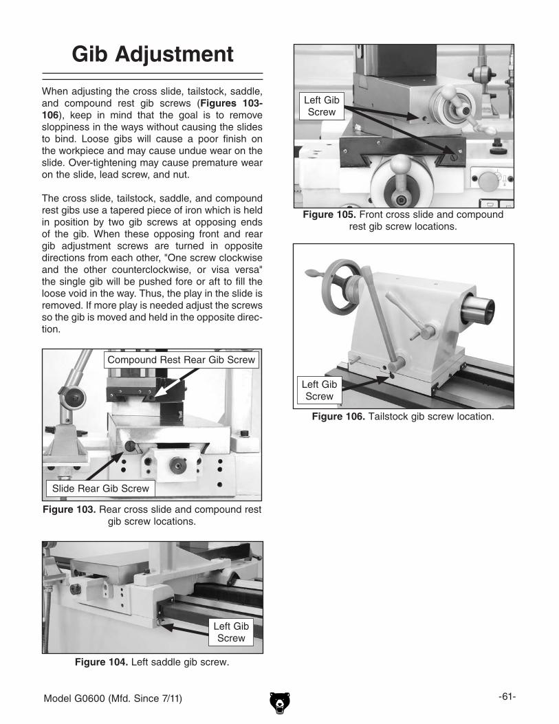
Model G0600 (Mfd. Since 7/11) -61-
When adjusting the cross slide, tailstock, saddle, and compound rest gib screws (Figures 103-106), keep in mind that the goal is to remove sloppiness in the ways without causing the slides to bind. Loose gibs will cause a poor finish on the workpiece and may cause undue wear on the slide. Over-tightening may cause premature wear on the slide, lead screw, and nut.
The cross slide, tailstock, saddle, and compound rest gibs use a tapered piece of iron which is held in position by two gib screws at opposing ends of the gib. When these opposing front and rear gib adjustment screws are turned in opposite directions from each other, "One screw clockwise and the other counterclockwise, or visa versa" the single gib will be pushed fore or aft to fill the loose void in the way. Thus, the play in the slide is removed. If more play is needed adjust the screws so the gib is moved and held in the opposite direc-tion.
Gib Adjustment
Figure 103. Rear cross slide and compound rest gib screw locations.
Slide Rear Gib Screw
Compound Rest Rear Gib Screw
Left Gib Screw
Figure 104. Left saddle gib screw.
Figure 105. Front cross slide and compound rest gib screw locations.
Left Gib Screw
Figure 106. Tailstock gib screw location.
Left Gib Screw

-62- Model G0600 (Mfd. Since 7/11)
Feed Clutch Adjustment
This lathe is designed with a feed clutch. This cone type clutch helps protect the apron feed system from overload. The feed clutch comes set from the factory. However, after the lathe becomes broken in, you may have to readjust this setting.
To adjust the clutch release point:
1. Using a 5mm hex wrench, turn the center cap screw clockwise to increase the clutch holding power, and turn counterclockwise to decrease the clutch holding power (Figure 108).
2. Start the lathe.
3. Engage the power feed and hold the lon-gitudinal feed handwheel with one hand. The clutch should release within a few sec-onds without you fighting handwheel rotation. When it does, the holding force is approxi-mately 12 kg.
4. Readjust the clutch screw as required to achieve the 12 kg setting.
Clutch Screw
Halfnut Adjustment
When adjusting the halfnut gibs remove the thread dial to expose the two gib screws (Figure 107). Your goal is to remove sloppiness in the ways without causing the half nut to bind. You will loosen the jam nuts and turn the two set screws clockwise until slight tension is felt in the set screw. The gibs will then be slightly pre-loaded. Tighten the jam nuts when finished.
Figure 107. Halfnut gib adjustment.
Half Nut Gib Adjustments
Points (Thread Dial Removed)
Leadscrew
Apron
Figure 108. Feed clutch.

Model G0600 (Mfd. Since 7/11) -63-
V-Belts
To adjust or replace the V-belts on the lathe:
1. DISCONNECT LATHE FROM POWER!
2. Open rear cover on the lathe base (Figure 109).
3. Use a 24mm wrench and adjust the belt tension hex nuts (see Figure 109) there is approximately 10mm belt deflection on each belt when pressed firmly in the center in between the pulleys.
Note: Replace all three belts as a matched set even if one shows cracking, glazing, or fraying.
4. Reinstall the rear cover.
Brake and Switch
To adjust the brake and brake switch:
1. DISCONNECT LATHE FROM POWER!
2. Remove the side motor cover.
3. Use a 16mm wrench and adjust the brake rod (Figure 110) so, when the foot pedal is pressed, the brake band firmly clamps the drum. When released the brake band should be loose on the drum.
Note: Replace the brake band when the fric-
tion material is worn down to approximately 2mm thick.
4. Use a 5mm hex wrench and adjust the brake switch cam so when in the released position, there is 3 to 5mm gap between the cam and the brake switch pushrod (Figure 110).
5. Reinstall safety cover and test foot brake operation.
Figure 109. V-belt adjustment.
Belt Tension Adjustment
Figure 110. Brake band and switch.
Brake Rod
3-5 mmGap
Brake Switch Cam and Cap screw
After consistent lathe usage, it will be necessary to compensate for brake lining wear.
After consistent lathe usage, it will be necessary to compensate for belt wear.
PulleyDeflection
Pulley

-64- Model G0600 (Mfd. Since 7/11)
Control Panel Electrical
Figure 111. Control panel switches.
SB2Jog Switch
SA1Power ON/OFF Switch
SA2Pump Switch
Power Lamp
SB1Emergency Stop Switch

Model G0600 (Mfd. Since 7/11) -65-
Figure 112. Pump wiring (M2).
Figure 116. Main power switch (S).
Figure 115. Spindle motor wiring (M1).
Figure 113. Spindle rotation switch (SQ1, SQ2).
Figure 114. Brake switch (SQ4). Figure 117. Gear cover limit switch (SQ3).
Switch and Motor Electrical

-66- Model G0600 (Mfd. Since 7/11)
Main Electrical Box
Figure 118. Electrical box.
Spindle MotorContactor (KM1)
Spindle MotorContactor (KM2)
Spindle MotorThermal Relay
(FR1)
Pump MotorContactor (KM3)
Pump MotorThermal Relay
(FR2)
Transformer (TC)
50A Master Power Switch/
Relay (S)
Master Power Contactor
(KM4)
Main Terminal Block
6A Fuse(FU2)
3A Fuse(FU3)
Spindle Motor Terminal Block
Ground Block

Model G0600 (Mfd. Since 7/11) -67-
Model G0600 Electrical Diagram
If a phase converter is being used, connect the “Wild Wire” or “ManufacturedLeg” to L3 or contactor andtransformer failure mayresult.

-68- Model G0600 (Mfd. Since 7/11)
1
3, 2
4
5
6
7
9,8
10
11 12 13 14 1516
17 18 19 20 21 22 23 24 25 26 27 28 29 30 31 32 33 34
35
36
3738
39
40
41
42
43
44
45
4647
48
49
50
5152
5354555657
58
59
60
61
62
63
64
6566676869707172737475
76
77
79, 78
80
81
8283
85, 84
86
8789, 88
90
91 93 94 95 96 97 98 99 100101
102103
104105
106107
108 109
110111
112113114115116117118119120121122
123124125
126
127 128 129
130131
132
133134 135 136 137
92
Headstock Gear System(0000 Series Parts)

Model G0600 (Mfd. Since 7/11) -69-
49
138
139
140
141
142
143
144
221
146147
148 149 150
219
222223
230
220
145
49
138
139
140
141
142
143
144
221
146147
148 149 150
219
222223
230
220
145
Headstock Face and Shift System(0000 Series Parts)

-70- Model G0600 (Mfd. Since 7/11)
151152
153154
155156157158
159
160
161
162
163164
165166,224
167
169170 171 172 173
174
175
176
177
178
179
180
181
182
183
184
185
186
187188189
190
191
192
193194
195196
225
226
227
228229
183
180
Headstock Shift System(0000 Series Parts)

Model G0600 (Mfd. Since 7/11) -71-
200201202203
204
205
206
207
208
209
210
211 212 213 214 215 216 217 218
199 198 197
231
Headstock Oil Pump System(0000 Series Parts)

-72- Model G0600 (Mfd. Since 7/11)
REF PART # DESCRIPTION REF PART # DESCRIPTION1 PSB02M CAP SCREW M6-1 X 20 51 PSB29M CAP SCREW M6-1 X 402 P06000002 BEARING COVER 52 P06000052 FRONT BEARING COVER3 P06000003 BEARING COVER SEAL 53 P06000053 FRONT BEARING COVER SEAL4 P06000004 SPLINE SHAFT 54 P06000054 BALL BEARING D2007124E5 P6205 BALL BEARING 6205 55 P06000055 GEAR 72T X M2.756 PSB01M CAP SCREW M6-1 X 16 56 P06000056 GEAR 50T X M2.757 P06000007 INPUT SHAFT 57 P06000057 SHAFT8 P06000008 SPANNER NUT M30 X 1.5 58 P6205 BALL BEARING 62059 P06000009 LOCK WASHER 30MM 59 P06000059 SHAFT10 PK41M KEY 8 X 8 X 40MM 60 P6205 BALL BEARING 620511 P06000011 PULLEY 61 PR15M EXT RETAINING RING 30MM12 P06000012 OIL SEAL 62 P6205 BALL BEARING 620513 PSB07M CAP SCREW M6-1 X 30 63 PR15M EXT RETAINING RING 30MM14 P06000014 BALL BEARING 1080908 64 PK129M KEY 8 X 8 X 36MM15 P06000015 BEARING CAP 65 P06000065 GEAR 48T X M2.2516 P06000016 BEARING SEAT SEAL 66 P06000066 OUTPUT SHAFT17 PR38M INT RETAINING RING 62MM 67 PK41M KEY 8 X 8 X 40MM18 P6306 BALL BEARING 6306 68 P06000068 GEAR 36T X M2.2519 PR15M EXT RETAINING RING 30MM 69 PR15M EXT RETAINING RING 30MM20 P06000020 SPACER 70 P06000070 SPACER21 P06000021 GEAR 39T X M2.75 71 P06000071 GEAR 30T X M2.2522 P06000022 KEY 8 X 8 X 70MM 72 P06000072 IDLER SHAFT23 P06000023 GEAR 20T X M2.75 73 P06000073 O-RING 30 X 2.4MM24 P06000024 SPACER 74 P06000074 SPACER25 P6205 BALL BEARING 6205 75 PSB01M CAP SCREW M6-1 X 1626 P06000026 GEAR 40T X M2.75 76 P06000076 BRASS BUSHING27 P06000027 GEAR 33T X M2.75 77 P6206 BALL BEARING 620628 P06000028 GEAR 47T X M2.75 78 P06000078 BEARING SEAT29 P6206 BALL BEARING 6206 79 P06000079 BEARING SEAT SEAL30 P06000030 GEAR 46T X M2.75 80 P06000080 BALL BEARING 108090831 P06000031 GEAR 24T X M2.75 81 P06000081 OIL SEAL32 P06000032 SPLINE SHAFT 82 PK32M KEY 6 X 6 X 28MM33 P6305 BALL BEARING 6305 83 PSB02M CAP SCREW M6-1 X 2034 P06000034 SPACER WASHER 84 P06000084 BEARING COVER35 P06000035 O-RING 56 X 2.65MM 85 P06000085 BEARING COVER SEAL36 P06000036 COVER 86 P6205 BALL BEARING 620537 PR38M INT RETAINING RING 62MM 87 PSB01M CAP SCREW M6-1 X 1638 P6305 BALL BEARING 6305 88 P06000088 BEARING COVER39 P06000039 LOCK WASHER 89 P06000089 BEARING COVER SEAL40 P06000040 O-RING 56 X 2.65MM 90 PSB01M CAP SCREW M6-1 X 1641 P06000041 COVER 91 P06000091 LOCK NUT42 P06000042 SPLINE SHAFT 92 P06000092 BRASS BUSHING43 PR38M INT RETAINING RING 62MM 93 PSS30M SET SCREW M10-1.5 X 1044 P06000044 EXT RETAINING RING 75MM 94 P06000094 BALL BEARING 12045 P06000045 GEAR 47T X M2.75 95 P06000095 GEAR 32T X M2.7546 P06000046 D1-8 CAM LOCK 96 PK107M KEY 8 X 8 X 20MM47 P06000047 SPECIAL D1-8 SCREW 97 PR26M INT RETAINING RING 52MM48 P06000048 COMPRESSION SPRING 98 P06000098 GEAR 51T X M2.7549 P06000049 SPINDLE 99 P06000099 KEY 10 X 10 X 80MM50 P06000050 D1-8 STUD

Model G0600 (Mfd. Since 7/11) -73-
REF PART # DESCRIPTION REF PART # DESCRIPTION100 PR32M EXT RETAINING RING 48MM 150 P06000150 SHAFT101 P06000101 GEAR 31T X M2.75 151 P06000151 FORK102 PK09M KEY 8 X 8 X 32MM 152 PEC03M E-CLIP 10MM103 PSS16M SET SCREW M8-1.25 X 10 153 P06000153 LEVER104 P06000104 GEAR 24T X M2.75 154 PRP26M ROLL PIN 5 X 26MM105 P06000105 BALL BEARING D2007122E 155 P06000155 SHAFT106 P06000106 SPACER 156 P06000156 GUIDE PIN107 P6205 BALL BEARING 6205 157 P06000157 SET SCREW M10-1.5 X 25108 PSS75M SET SCREW M10-1.5 X 16 158 P06000158 O-RING 22 X 2.4MM109 P06000109 KEY 10 X 10 X 90MM 159 P06000159 LOCK WASHER110 P06000110 LOCK NUT 160 P06000160 SPECIAL DOME SCREW111 P06000111 BRASS BUSHING 161 PSS20M SET SCREW M8-1.25 X 8112 P06000112 LOCK NUT 162 P06000162 LEVER113 P06000113 BRASS BUSHING 163 P06000163 SHAFT114 PR15M EXT RETAINING RING 30MM 164 PK10M KEY 5 X 5 X 12MM115 P06000115 GEAR 24T X M2.25 165 P06000165 HANDLE HUB116 P06000116 KEY 8 X 8 X 70MM 166 P06000166 SPACER PLATE117 P06000117 GEAR 36T X M2.25 167 P06000167 LEVER118 P06000118 GEAR 55T X M2.25 169 P06000169 O-RING 20 X 2.4MM119 P06000119 GEAR 55T X M2.25/55T X M2.25 170 PSS02M SET SCREW M6-1 X 6120 P06000120 SHAFT RING 171 PRP26M ROLL PIN 5 X 26MM121 P06000121 OIL RING 172 P06000172 GEAR 35T X M2122 P06000122 REAR BEARING COVER 173 P06000173 GEAR 25T X M2123 P06000123 BEARING COVER SEAL 174 P06000174 RUBBER MAT124 PSS03M SET SCREW M6-1 X 8 175 P06000175 HEADSTOCK COVER125 P06000125 COUNTERWEIGHT 176 P06000176 SHAFT126 P06000126 EXT RETAINING RING 34MM 177 P06000177 PLUG127 P06000127 GEAR 38T X M2.75 178 PRP05M ROLL PIN 5 X 30MM128 P06000128 GEAR 25T X M2.75 179 P06000179 FORK129 P06000129 KEY 180 P06000180 LEVER130 P06000130 KEY 8 X 8 X 90MM 181 P06000181 HEADSTOCK131 P6205 BALL BEARING 6205 182 P06000182 FORK132 P06000132 GEAR 48T X M2.25 183 PEC12M E-CLIP 12MM133 PR32M EXT RETAINING RING 48MM 184 P06000184 GEAR 42T X M2134 PK49M KEY 6 X 6 X 55MM 185 P06000185 GEAR 18T X M2135 P06000135 GEAR 36T X M2.25 186 P06000186 HUB136 P06000136 KEY 8 X 8 X 90MM 187 P06000187 SHAFT137 P06000137 GEAR 24T X M2.25 188 P06000188 HANDLE LEVER BLOCK138 P06000138 CAP SCREW M16-2 X 55 189 PK10M KEY 5 X 5 X 12MM139 P06000139 INDICATOR PLATE 190 PRP39M ROLL PIN 4 X 20MM140 P06000140 INDICATOR PLATE 191 P06000191 LEVER141 P06000141 RIVET 2 X 5MM 192 PK10M KEY 5 X 5 X 12MM142 P06000142 INDICATOR PLATE 193 P06000193 HANDLE HUB143 P06000143 LEVER 194 P06000194 SHAFT144 P06000144 FORK 195 P06000195 LEVER145 P06000145 OIL SIGHT GLASS 196 P06000196 FORK146 P06000146 INDICATOR PLATE 197 P06000197 O-RING 68 X 3.1MM147 P06000147 POINTER PLATE 198 P06000198 COVER148 P06000148 GEAR 31T X M2 199 P06000199 BRASS TUBE 4 X 0.75"149 P06000149 GEAR 35T X M2

-74- Model G0600 (Mfd. Since 7/11)
REF PART # DESCRIPTION REF PART # DESCRIPTION200 PSB38M CAP SCREW M5-.8 X 25 216 P06000216 SEAL SLEEVE201 P06000201 MANIFOLD 217 PLW12M SEAL WASHER202 P06000202 SEAL SLEEVE 218 P06000218 SCREEN203 P06000203 BRASS FITTING 219 P06000219 PLUG204 P06000204 BRASS TUBE 8 X 0.75" 220 P06000220 TUBE FITTING205 P06000205 GEAR 20T X M2.75 221 PLW10M LOCK WASHER 16MM206 PSB26M CAP SCREW M6-1 X 12 222 P06000222 CAP SCREW M16-2 X 45207 PSB01M CAP SCREW M6-1 X 16 223 P06000223 ANCHOR PIN 16 X 60208 P06000208 BRASS FITING 224 PSB01M CAP SCREW M6-1 X 16209 P06000209 SEALING SLEEVE 225 P06000225 HANDLE HUB210 P06000210 BRASS FITTING 226 PS22M PHLP HD SCR M5-.8 X 25211 P06000211 SEAL WASHER 227 P06000227 OIL PLUG212 P06000212 OIL PUMP 228 P06000228 STEEL BALL 1/4"213 P06000213 BRASS FITTING 229 P06000229 COMPRESSION SPRING214 P06000214 BRASS TUBE 10 X 0.75" 230 PSB14M CAP SCREW M8-1.25 X 20215 P06000215 BRASSS FITTING 231 P06000231 BRASS FITTING

Model G0600 (Mfd. Since 7/11) -75-
1001
10031006
1007100810091010
1011 1012
1013 1014
1015
1016
1017
1018
1020
1022
1023
1024
1025
1026
1027102810291030
1031
1032
1033
1034 10351036
1038
1039
1093
10411042
104310441045
10461047
10481049
1050 10511052
10531054
1055
1056
1057
1059
1060
1063
1064
10661067
1068
10691070
1071
1073
1032
1040
111710311031
1038
1025
1034
1039
10931058
1073
103110201001
10031006
1007100810091010
1011 1012
1013 1014
1015
1016
1017
1018
1020
1022
1023
1024
1025
1026
1027102810291030
1031
1032
1033
1034 10351036
1038
1039
1093
10411042
104310441045
10461047
10481049
1050 10511052
10531054
1055
1056
1057
1059
1060
1063
1064
10661067
1068
10691070
1071
1073
1032
1040
111710311031
1038
1025
1034
1039
10931058
1073
10311020
Quick Change Gearbox Gear System(1000 Series Series Parts)

-76- Model G0600 (Mfd. Since 7/11)
1098
1115
10211114
110311111061
1128
1127
1112
11101109
1019
11161103
1126
1113
1037
1002
10721077
10741108
1002
1019
1021
10371061
1072
10741077
1098
1103
11031108
1110
1111
1112
11131114
1115
1116
1126
1127
1128
Quick Change Gearbox Face(1000 Series Parts)

Model G0600 (Mfd. Since 7/11) -77-
Quick Change Gearbox Shift System(1000 Series Parts)
1078
1079
1081
1082
1083
1084
1085
1086
1090
1091
1092
1094
1095
1096
1097
1099
1018
1101
1121
1103
1023
11291122
1088
1124
1104

-78- Model G0600 (Mfd. Since 7/11)
Quick Change Gearbox Shift System(1000 Series Parts)
1004
1005 1062
1065
1075
1076
1080 1087
1089
1099
1100 11021105 1106 1107
1118
1119 1120
1099
10971004
1005 1062
1065
1075
1076
1080 1087
1089
1099
1100 11021105 1106 1107
1118
1119 1120
1099
1097

Model G0600 (Mfd. Since 7/11) -79-
REF PART # DESCRIPTION REF PART # DESCRIPTION1001 P06001001 GEAR BOX 1051 P06001051 GEAR 27T X 14D.P1002 P06001002 FRONT COVER 1052 P06001052 GEAR 24T X M2.251003 P06001003 BEVEL GEAR 1053 P06001053 GEAR 26T X M2.251004 P06001004 HEX BOLT 1054 P06001054 GEAR 36T X M21005 P06001005 FLAT WASHER 1055 P06001055 GEAR 27T X 12D.P1006 P06001006 SHIFTER CLAW 1056 P06001056 GEAR 28T X 12D.P1007 P06001007 SHIFTER CLAW 1057 P06001057 GEAR 50T X M1.25/20T X M21008 P06001008 SHIFTER CLAW 1058 P06001058 F-SHAFT1009 P06001009 SHIFTER CLAW 1059 PR07M EXT RETAINING RING 18MM1010 P06001010 SHIFTER CLAW 1060 P06001060 THRUST BEARING 81041011 PRP91M ROLL PIN 5 X 35MM 1061 P06001061 END CAP1012 P06001012 CAM SHIFTER 1062 P06001062 STEEL BALL 1/4"1013 P06001013 RETAINER 1063 P06001063 C-SHAFT1014 PSS16M SET SCREW M8-1.25 X 10 1064 P06001064 GEAR 35T X M1.25/35T X M21015 P06000158 O-RING 22 X 2.4MM 1065 P06001065 ARM1016 P06001016 H-SHAFT 1066 PK48M KEY 4 X 4 X 20MM1017 PRP91M ROLL PIN 5 X 35MM 1067 P06001067 BALL BEARING 1801051018 PSS25M SET SCREW M6-1 X 20 1068 P06001068 A-SHAFT1019 P06001019 RECEIVER HUB 1069 P06001069 GEAR 18T X M2/23T X 11D.P1020 PSB02M CAP SCREW M6-1 X 20 1070 P06001070 GEAR 36T X M21021 P06001021 END CAP (RIGHT) 1071 P06001071 GEAR 19T X 10D.P/19T X 14D.P1022 P06001022 OIL SEAL 1072 P06001072 B-SHAFT1023 P06001023 BALL BEARING 180204 1073 P06001073 CLUTCH1024 P06001024 GEAR 36T X M1.25 1074 P06001074 CAP1025 PR11M EXT RETAINING RING 25MM 1075 P06001075 FORK1026 P06001026 GEAR 22T X 12D.P 1076 P06001076 FORK1027 P06001027 GEAR 22T X M2.25 1077 P06001077 SPACER1028 P06001028 GEAR 33T X 14D.P 1078 PRP05M ROLL PIN 5 X 30MM1029 P06001029 GEAR 22T X 11D.P 1079 P06001079 BEVEL GEAR1030 P06001030 GEAR 22T X 10D.P 1080 P06001080 SPEED CHANGE HUB1031 P06001031 BALL BEARING 180104 1081 P06001081 LEVER HUB1032 P06001032 EXT RETAINING RING 20MM 1082 P06001082 SPACER1033 P06001033 GEAR 22T X 10D.P 1083 P06001083 SHAFT SLEEVE1034 PK07M KEY 6 X 6 X 20MM 1084 P06001084 O-RING 16 X 2.4MM1035 P06001035 G-SHAFT 1085 P06001085 SHIFT FORK1036 P06001036 BALL BEARING 180103 1086 P06001086 DIAL HUB1037 P06001037 COVER 1087 PK19M KEY 5 X 5 X 14MM1038 PSB26M CAP SCREW M6-1 X 12 1088 P06001088 ARM1039 P06001039 O-RING 35 X 3.5MM 1089 P06001089 CAP SCREW M8-1.25 X 81040 P06001040 E-SHAFT 1090 P06001090 HAND KNOB1041 P06001041 GEAR 20T X 10D.P/40T X 14D.P 1091 PSB40M CAP SCREW M8-1.25 X 351042 P06001042 BALL BEARING 180203 1092 PSB71M CAP SCREW M10-1.5 X 601043 P06001043 D-SHAFT 1093 PSB01M CAP SCREW M6-1 X 161044 P06001044 KEY 6 X 6 X 146MM 1094 PK131M KEY 5 X 5 X 28MM1045 P06001045 GEAR 19T X 10D.P 1095 PSB72M CAP SCREW M10-1.5 X 301046 P06001046 GEAR 18T X M2 1096 P06001096 TAPER PIN 10 X 45MM1047 P06001047 GEAR 20T X 10D.P 1097 P06001097 SPECIAL DOME SCREW1048 P06001048 GEAR 22T X 11D.P 1098 PSB49M CAP SCREW M6-1 X 601049 P06001049 GEAR 23T X 11D.P 1099 P06001099 DETENT PLATE1050 P06001050 GEAR 24T X 14D.P

-80- Model G0600 (Mfd. Since 7/11)
REF PART # DESCRIPTION REF PART # DESCRIPTION1100 P06001100 ARM 1116 P06000141 RIVET 2 X 5MM1101 P06001101 SHAFT 1117 P06001117 OIL-SEAL1102 P06001102 FORK 1118 P06001118 FEMALE KNOB M10-1.51103 PSB37M CAP SCREW M6-1 X 50 1119 P06001119 SHAFT1104 P06001104 LOCK WASHER 1120 PRP05M ROLL PIN 5 X 30MM1105 P06001105 COMPRESSION SPRING 1121 P06001121 LEVER1106 P06001084 O-RING 16 X 2.4MM 1122 PS09M PHLP HD SCR M5-.8 X 101107 P06000073 O-RING 30 X 3.1MM 1123 PS22M PHLP HD SCR M5-.8 X 251108 PSB07M CAP SCREW M6-1 X 30 1124 P06001124 SPACER1110 PSB07M CAP SCREW M6-1 X 30 1125 PRP24M ROLL PIN 5 X 16MM1111 P06001111 POINTER PLATE 1126 P06001126 OIL PLUG1112 P06001112 INDICATOR PLATE 1127 P06001127 OIL PLUG1113 P06001113 OIL SIGHT GLASS 1128 P06001128 TOP COVER1114 P06001114 INDICATOR PLATE 1129 P06001129 HANDLE HUB1115 P06001115 INDICATOR PLATE

Model G0600 (Mfd. Since 7/11) -81-
Carriage
2044
2045
2046
2048
2052
2056
2078
2079
2080
2081
2090
2091
(2000 Series Parts)
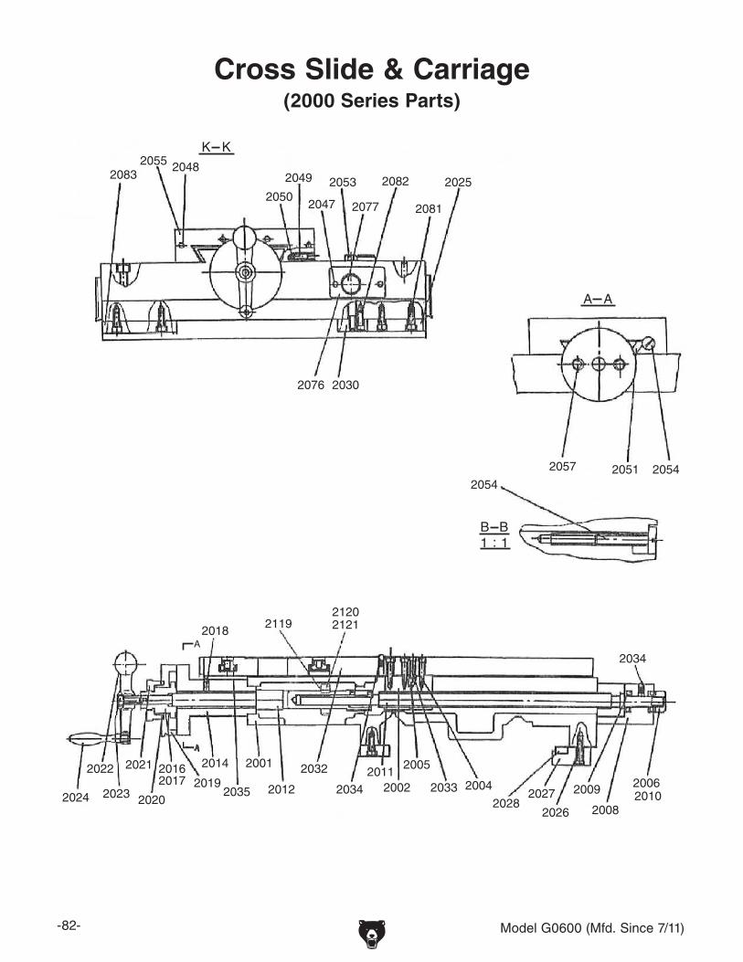
-82- Model G0600 (Mfd. Since 7/11)
Cross Slide & Carriage(2000 Series Parts)
20832055 2048
2049
2047
2053 2082 2025
2076 2030
2057 2051 20542054
2034
20062010
2008
2009
2026
20272028
200420332002203420122035
2014
201920162017
2020
2021
2023
2022
2024
212021212119
2018
2032
A
K K
208120772050
A A
1 1:B B
2001 20052011

Model G0600 (Mfd. Since 7/11) -83-
2003
20072013
20152029 2031
2034
2037
2038
2039
2040
2041
2042
2043
2049
2050
2058
20592060
20612062
2063
20642065
2066 2067
2068
2069
20702071
2072
2073
2074
2075
208420852086 2087
2088
2089
2092
2093
2094
Compound Slide & Tool Post(2000 Series Parts)
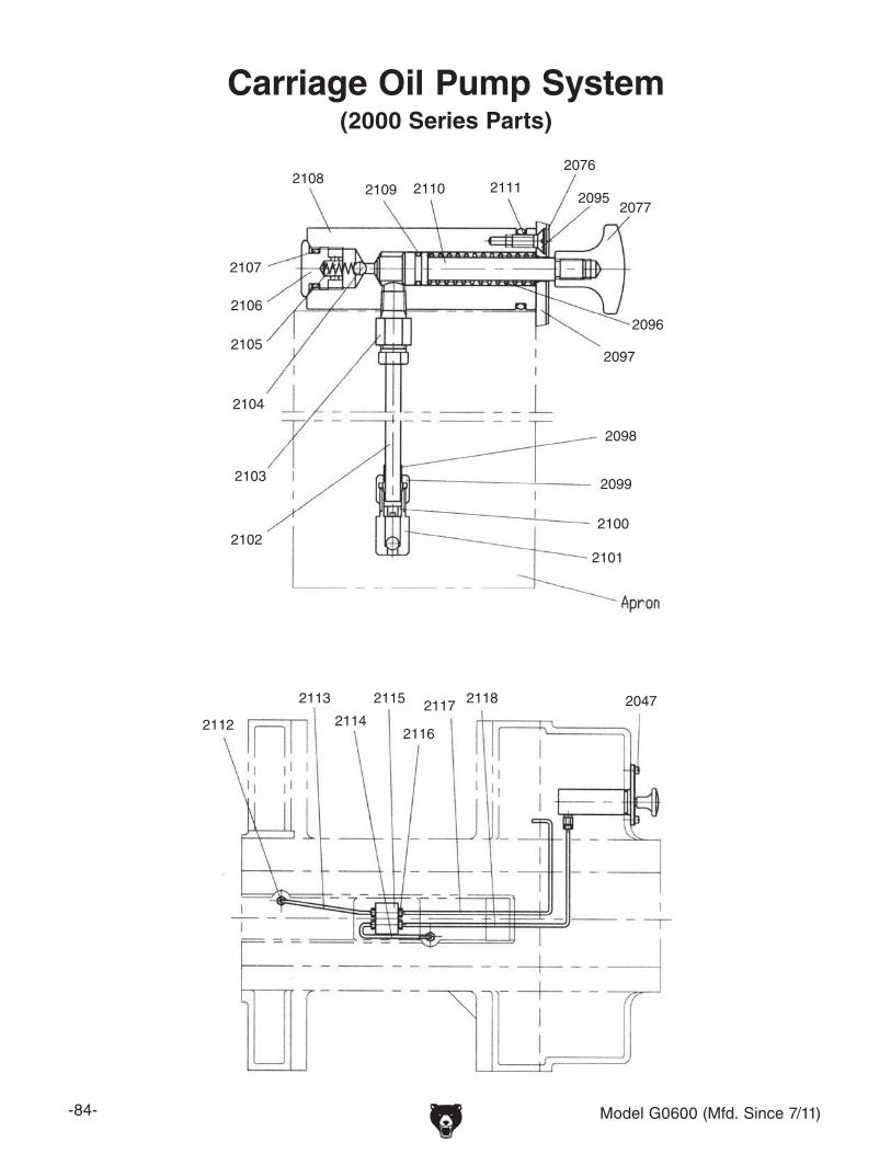
-84- Model G0600 (Mfd. Since 7/11)
2047
2076
20772095
2096
2097
2098
2099
2100
21012102
2103
2104
2105
2106
2107
21082109 2110 2111
2112
2113
2114
2115
2116
2117 2118
Carriage Oil Pump System(2000 Series Parts)

Model G0600 (Mfd. Since 7/11) -85-
REF PART # DESCRIPTION REF PART # DESCRIPTION
2000 P06002000 FLANGE NUT M20-2.5 2051 P06002051 GIB
2001 P06002001 SADDLE 2052 P06002052 RUBBER WIPER
2002 P06002002 NUT (INCH) 2053 P06002053 CARRIAGE CLAMP
2003 P06002003 GIB SCREW 2054 P06002054 GIB SCREW
2004 PSB48M CAP SCREW M6-1 X 35 2055 P06002055 RUBBER WIPER
2005 P06002005 GIB 2056 P06002056 WIPER
2006 PSB68M CAP SCREW M6-1 X 8 2057 P06002057 SET SCREW M8-1.25 X 70
2007 P06002007 HANDLE 2058 P06002058 SPANNER NUT
2008 P06002008 BRACKET 2059 P06002059 THRUST BEARING 8102
2009 P06002009 THRUST BEARING 8101 2060 PSS01M SET SCREW M6-1 X 10
2010 P06002010 HEX NUT 2061 P06002061 BARREL NUT
2011 P06002011 CROSS FEED SCREW (INCH) 2062 P06002062 WAVY WASHER
2012 P06002012 CROSS FEED PINION 2063 P06002063 DIAL-COMPOUND REST (INCH)
2013 PSB04M CAP SCREW M6-1 X 10 2064 P06002064 CLUTCH DIAL
2014 P06002014 BRACKET 2065 P06002065 DIAL HOUSING
2015 P06002015 HANDLE 2066 P06002066 HALF NUT (INCH)
2016 PSS03M SET SCREW M6-1 X 8 2067 P06002067 LEAD SCREW
2017 P06002017 CLUTCH-DIAL 2068 P06002068 TOOL POST SHAFT
2018 P06002018 BALL OILER 2069 P06002069 GIB
2019 P06002019 CROSS FEED DIAL 2070 P06002070 GUIDE PIN
2020 P06002020 WAVY WASHER 2071 P06002071 SLEEVE
2021 P06002021 BARREL NUT 2072 P06002072 COMPRESSION SPRING
2022 P06002022 CRACK HANDLE 2073 PSB02M CAP SCREW M6-1 X 20
2023 PSB11M CAP SCREW M8-1.25 X 16 2074 PSS31M SET SCREW M5-.8 X 8
2024 P06002024 HANDLE 2075 PSB85M CAP SCREW M6-1 X 6
2025 P06002025 GIB (LEFT-FRONT) 2076 P06002076 END PLATE
2026 PSB13M CAP SCREW M8-1.25 X 30 2077 P06002077 HANDLE
2027 P06002027 GIB CRADLE 2078 PSB71M CAP SCREW M10-1.5 X 60
2028 P06002028 GIB 2079 P06002079 TAPER PIN 8 X 60MM
2029 PSB90M CAP SCREW M10-1.5 X 55 2080 P06002080 OIL PLUG
2030 P06002030 CARRIAGE CLAMP 2081 PSB14M CAP SCREW M8-1.25 X 20
2031 P06002031 KNURLED WASHER 2082 PSB02M CAP SCREW M6-1 X 20
2032 P06002032 CROSS SLIDE COVER 2083 P06002083 GIB (FRONT)
2033 PSB13M CAP SCREW M8-1.25 X 30 2084 PS02M PHLP HD SCR M4-.7 X 12
2034 P06002034 BALL OILER 2085 P06002085 RUBBER WIPER
2035 P06002035 HEX NUT 2086 P06002086 RUBBER WIPER
2037 PSB47M CAP SCREW M10-1.5 X 40 2087 P06002087 TOOL HOLDER SPECIAL SERIES
2038 P06002038 COMPOUND REST 2088 PN09M HEX NUT M12-1.75
2039 P06002039 TOOL POST SPECIAL 500 SERIES 2089 PSB12M CAP SCREW M8-1.25 X 40
2040 P06002040 SQUARE HEAD BOLT M12-1.75 X 50 2090 P06002090 RUBBER WIPER
2041 P06002041 BARREL SLEEVE 2091 P06002091 RUBBER WIPER
2042 P06002042 HANDLE HUB 2092 P06002092 STUD M12-1.75 X 60
2043 P06002043 LEVER M12-1.75 2093 P06002093 PISTON FOOT
2044 P06002044 RUBBER WIPER 2094 P06002094 CAP SCREW M16-2 X 12
2045 P06002045 RUBBER WIPER 2095 PFH07M FLAT HD SCR M5-.8 X 10
2046 P06002046 RUBBER WIPER 2096 P06002096 COMPRESSION SPRING
2047 PS08M PHLP HD SCR M5-.8 X 12 2097 P06002097 BOTTOM PLATE
2048 PS02M PHLP HD SCR M4-.7 X 12 2098 P06002098 TUBE FITTING
2049 PSB52M CAP SCREW M8-1.25 X 10 2099 P06002099 TUBE NUT
2050 P06002050 STEEL BALL 1/4"

-86- Model G0600 (Mfd. Since 7/11)
REF PART # DESCRIPTION REF PART # DESCRIPTION
2100 P06002100 SLEEVE 2112 P06002112 TUBE FITTING
2101 P06002101 CHECK VALVE 2113 P06002113 BRASS TUBE 4 X 200MM
2102 P06002102 BRASS TUBE 6 X 170MM 2114 P06002114 BRASS TUBE 4 X 170MM
2103 P06002103 TUBE FITTING 2115 P06002115 MANIFOLD
2104 P06002104 STEEL BALL 5MM 2116 P06002116 SLEEVE AND FITTING
2105 P06002105 COMPRESSION SPRING 2117 P06002117 BRASS TUBE 4 X 390MM
2106 P06002106 END PLUG 2118 P06002118 BRASS TUBE 4 X 410MM
2107 P06001084 O-RING 16 X 2.4MM 2119 PR58M EXT RETAINING RING 24MM
2108 P06002108 PUMP BODY 2120 P06002120 GEAR 19T X M2
2109 P06002109 O-RING 9 X 1.8MM 2121 PK70M KEY 8 X 8 X 12MM
2110 P06002110 PISTON ROD 2122 P06002122 FEMALE KNOB M12-1.75
2111 P06002111 O-RING 32 X 3.1MM 2123 P06002123 FEMALE KNOB M12-1.75

Model G0600 (Mfd. Since 7/11) -87-
30013003
3006
3008
3018
3019 3020
302130223023
3024
302530263027
3028
30293030
3048
3049
305030523056
30603061
30643075 3082 3085
3096309730983099
310031013102
31033104
3106 3107 3108
3109
3110
3119
30593006
30573058
ThreadDial
3007
Apron Face, Thread Dial, Auto Stop System(3000 Series Parts)

-88- Model G0600 (Mfd. Since 7/11)
Apron Gearing, Halfnut, Feed System(3000 Series Parts)
3001
3002
3003
3004
3005
3006
3009
3010
3011
3012
3013
3017
3037
3057
3062
3063
30643066
3069
3074
3075
3076
3077
3078
3079
3080
3081
3082
3083
3084
3085
3086
3087
3088
3090
3091
3092
3093
3094
3095
3105
3112
3116
3006
3003
3032
3065
3070
3071
3072
3073
3089
3111
3113
3117
3118
3031
3033
3015
3047
3114
3115

Model G0600 (Mfd. Since 7/11) -89-
3014
3015
3016
30383039
3040
30423043
3044
3045
3049
3012
3017
3003
3012
3034
3036
3012
3035
3034
3041
3042
3053
3068
3046 30503051
3052
3054
3055
3051
Apron Feed Rod, Clutch and Lever System(3000 Series Parts)

-90- Model G0600 (Mfd. Since 7/11)
REF PART # DESCRIPTION REF PART # DESCRIPTION3001 P06003001 APRON CASE 3051 P06003051 SHAFT3002 P06003002 GIB 3052 P06003052 BUFFER3003 PSB26M CAP SCREW M6-1 X 12 3053 P06000169 O-RING 20 X 2.4MM3004 P06003004 LEAD NUT ASSY (INCH) 3054 P06003054 SLEEVE3005 P06003005 HAFT NUT (INCH) 3055 P06003055 LEVER HUB3006 PSB01M CAP SCREW M6-1 X 16 3056 PR01M EXT RETAINING RING 10MM3007 P06000141 RIVET 2 X 5MM 3057 P06003057 LEVER SHAFT3008 P06003008 OIL PLUG 3058 PSB58M CAP SCREW M8-1.25 X 123009 P06003009 KEY 3059 P06003059 SPECIAL SCREW3010 P06003010 SHAFT 3060 PS05M PHLP HD SCR M5-.8 X 83011 P06002111 O-RING 32 X 3.5MM 3061 P06003061 COMPRESSION SPRING3012 PSS16M SET SCREW M8-1.25 X 10 3062 P06003062 COVER3013 P06003013 SHAFT SLEEVE 3063 P06001067 BALL BEARING 1801053014 P06003014 STEEL BALL 1/4" 3064 P06003064 WORM GEAR3015 P06003015 COMPRESSION SPRING 3065 P06003065 GEAR 36T X M23016 PSB52M CAP SCREW M8-1.25 X 10 3066 PK70M KEY 8 X 8 X 12MM3017 P06003017 LEVER 3067 P06003067 SHAFT3018 P06003018 POINTER PLATE 3068 P06003068 GUIDE PIN3019 PRP35M ROLL PIN 5 X 10MM 3069 P06003069 SLEEVE3020 P06003020 OIL SIGHT 3070 P06003070 HANDLE LEVER3021 P06003021 GUIDE PIN 3071 PSS73M SET SCREW M10-1.5 X 303022 P06003022 BOTTOM COVER 3072 P6204 BALL BEARING 62043023 P06003023 OIL SEAL 3073 P06003073 COVER3024 P06003024 BRACKET 3074 PR09M EXT RETAINING RING 20MM3025 P06003025 DOWEL PIN 8 X 40MM 3075 P06003075 GEAR 46T X M2/18T X M23026 PSB85M CAP SCREW M6-1 X 6 3076 P06003076 SHAFT3027 P06003027 LEVER 3077 P06003077 PINION3028 P06003028 SPACER 3078 PK07M KEY 6 X 6 X 20MM3029 PSS19M SET SCREW M8-1.25 X 30 3079 PSB58M CAP SCREW M8-1.25 X 123030 PN03M HEX NUT M8-1.25 3080 P06003080 SPACER3031 P06003031 LEVER HUB 3081 P06003081 CAP SCREW M8-1.25 X 83032 P06003032 CHANGE SLEEVE 3082 P06003082 GEAR 61T X M23033 PS09M PHLP HD SCR M5-.8 X 10 3083 P06003083 BALL BEARING 1033034 P06003034 OIL SEAL 3084 P06003084 COVER3035 P06003035 BUSHING 3085 P06003085 SHAFT3036 P06003036 FEED ROD SLEEVE 3086 PK45M KEY 6 X 6 X 24MM3037 P06003037 PLUG 3087 P06003087 SEAT3038 PK81M KEY 6 X 6 X 12MM 3088 PSB06M CAP SCREW M6-1 X 253039 P06003039 GEAR 24T X M2 3089 P06003089 NEEDLE BEARING 46449033040 P06003040 WORM SEAT 3090 P06003090 BEARING 20103041 P06003041 SHAFT 3091 P06003091 DIAL-RACK3042 P06001060 THRUST BEARING 8104 3092 P06003092 HAND WHEEL3043 P06003043 WORM GEAR 3093 P06003093 HANDLE3044 P06003044 TAB WASHER 20MM 3094 P06003094 FLAT WASHER3045 P06003045 SPANNER NUT M20-1.5 3095 P06003095 SPECIAL SCREW3046 PSB02M CAP SCREW M6-1 X 20 3096 P06003096 DIAL FACE3047 P06003047 STEEL BALL 7/32" 3097 P06003097 DIAL INDICATOR SHAFT3048 P06003048 BLOCK 3098 P06003098 THREAD DIAL BODY3049 P06003049 FLAT WASHER 3099 P06003099 CAP SCREW M8-1.25 X 853050 P06003050 DOWEL PIN 8 X 25MM

Model G0600 (Mfd. Since 7/11) -91-
REF PART # DESCRIPTION REF PART # DESCRIPTION3100 PLW06M LOCK WASHER 10MM 3110 P06003110 INDICATOR PLATE3101 PN02M HEX NUT M10-1.5 3111 P06003111 SPACER3102 P06003102 DOWEL PIN 3 X 8MM 3112 P06003112 FLAT SPRING3103 P06003103 GEAR 16T X M2 3113 P06003113 COMPRESSION SPRING3104 P06003104 SPACER 3114 PN01M HEX NUT M6-13105 PSB38M CAP SCREW M5-.8 X 25 3115 PSS25M SET SCREW M6-1 X 203106 P06003106 INDICATOR PLATE 3116 P06003116 BALL OILER3107 P06003107 INDICATOR PLATE 3117 PS52M PHLP HD SCR M4-.7 X 203108 P06003108 FEMALE KNOB M10-1.5 3118 P06003118 SHOULDER WASHER3109 PS38M PHLP HD SCR M4-.7 X 10 3119 P06003119 INDICATOR PLATE

-92- Model G0600 (Mfd. Since 7/11)
Tailstock(4000 Series Parts)

Model G0600 (Mfd. Since 7/11) -93-
REF PART # DESCRIPTION REF PART # DESCRIPTION4001 P06004001 QUILL 4028 P06004028 SLEEVE4002V2 P06004002V2 TAILSTOCK BODY V2.07.11 4029 P06004029 ADJUSTMENT BLOCK4003 P06004003 OIL SEAL 4030 P06004030 SPECIAL SCREW4004 P06004004 BALL OILER 4031 P06004031 GIB4005 P06004005 FEED SCREW (INCH) 4037 P06004037 LEVER4006 PSB01M CAP SCREW M6-1 X 16 4038 P06004038 SHAFT4007 P06004007 FEED NUT (INCH) 4039 P06004039 SPECIAL SCREW4008 P06004008 THRUST BEARING 8105 4040 PSS65M SET SCREW M16-2 X 204009 PSB01M CAP SCREW M6-1 X 16 4041 P06004041 SHAFT4010 P06004010 END CAP 4042 P06004042 CLAMP SHOE4011 P06004011 DIAL-FEED (INCH) 4043 PLW07M LOCK WASHER 20MM4012 PK07M KEY 6 X 6 X 20MM 4044 P06004044 HEX BOLT M20-2.5 X 1504013 P06004013 HANDLE 4045 P06004045 HEX BOLT M20-2.5 X 1004014 PS22M PHLP HD SCR M5-.8 X 25 4046 PRP31M ROLL PIN 6 X 36MM4015 P06004015 FLAT WASHER 4047 P06004047 BALL OILER4016 P06004016 HANDLE WHEEL 4048 PSS24M SET SCREW M5-.8 X 254017 PN28M HEX NUT M20-2.5 4049 P06004049 SCALE PLATE4018 PLW07M LOCK WASHER 20MM 4050 P06000141 RIVET 2 X 5MM4019 P06004019 WIPER RETAINER 4051 P06004051 SCALE PLATE4020 P06004020 RUBBER WIPER 4052 P06004052 RUBBER WIPER4021 PS02M PHLP HD SCR M4-.7 X 12 4053 P06004053 WIPER PLATE4022 PSB04M CAP SCREW M6-1 X 10 4054 PSB62M CAP SCREW M10-1.5 X 124023 P06004023 PIN SHAFT 4055 PSS30M SET SCREW M10-1.5 X 104024 PB140M HEX BOLT M12-1.75 X 70 4056 P06004056 QUILL LOCK CLAMP ASSEMBLY4025 P06004025 TAILSTOCK BASE 4057 P06004057 LOCK LEVER ASSEMBLY4026 PLW05M LOCK WASHER 12MM 4058 P06004058 LOCK LEVER FLAT WASHER4027 P06004027 BOLT-CLAMP

-94- Model G0600 (Mfd. Since 7/11)
5001
5002
5003
5004 50
055006
5007
5008
5009
5010
5012
5013
5014
5015
5016
5018
5019
502050
215022
5023
5024
5025
5026
5027
5028
5029
5030
5031
503250
33
5034
5142
5143
5111
5115
511651
175118 51
19
5120
512151
225123
5124
5125
5126
5127
5128
5129
5130
5131
5132
5133
5134
5135
5136
5137
5138
5139
5140
5141
5169
5170
5171
5172
5173
Bed Assembly(5000 Series Parts)

Model G0600 (Mfd. Since 7/11) -95-
50835084 50855144 5145
5174
5176
Brake Pedal and Headstock Panels(5000 Series Parts)

-96- Model G0600 (Mfd. Since 7/11)
5035
5036
5037
50385039
5040
5041
5044
5045
5046
50475048 5049
5050
5051
5052 50535054
50555056
5057
50585059
5060
50615062
5063
5064
5065
5066
5067
5068
5069
5070
5071
5072
5073
5077
5078
5006
5037
5042
5043
5037
507950805081
5082
5035
5036
5037
50385039
5040
5041
5044
5045
5046
50475048 5049
5050
5051
5052 50535054
50555056
5057
50585059
5060
50615062
5063
5064
5065
5066
5067
5068
5069
5070
5071
5072
5073
5077
5078
5006
5037
5042
5043
5037
507950805081
5082
Brake System and Change Gears(5000 Series Parts)

Model G0600 (Mfd. Since 7/11) -97-
5017
5076
515151525153
51545155 51565157
51585159
5160
5161
5163
51645165
5166
5167
50845085
505550485052
5054
513750365123
512451645166
70215037
5066
5042
5162
5165
5051
5068
5037
5053
5175
5017
5076
515151525153
51545155 51565157
51585159
5160
5161
5163
51645165
5166
5167
50845085
505550485052
5054
513750365123
512451645166
5037
5066
5042
5162
5165
5051
5068
5037
5053
5175
Motor and Headstock Mounting(5000 Series Parts)

-98- Model G0600 (Mfd. Since 7/11)
5086
5087
5088
5089
50915149
5150
5148
509050875071
5086
5087
5088
5089
50915149
5150
5148
509050875071
End Covers and Splash Guard(5000 Series Parts)

Model G0600 (Mfd. Since 7/11) -99-
Change Gear System(5000 Series Parts)
5073
5074
5075
5078
5079
5080
5082
5086
5093
5094
5095
5097
5098
5099
5100
5101
5102
51035104
5105
51065110
5111
5112
5146
5147
5108
5109
5114
5093
5113
5081

-100- Model G0600 (Mfd. Since 7/11)
REF PART # DESCRIPTION REF PART # DESCRIPTION5001 P06005001 SWITCH SEAT 5049 P06005049 SHAFT5002 P06005002 LEAD SCREW (INCH) 5050 P06005050 TENSION SPRING5003 P06005003 RACK 5051 P06005051 SHAFT5004 PRP05M ROLL PIN 5 X 30MM 5052 P06005052 BRAKE LEVER5005 PSB06M CAP SCREW M6-1 X 25 5053 P06005053 CAM5006 P06005006 BED 5054 P06005054 SHAFT5007 P06005007 TAPER PIN 10 X 45MM 5055 P06005055 MOTOR SEAT BRACKET5008 PSB47M CAP SCREW M10-1.5 X 40 5056 P06005056 LIMIT SWITCH5009 P06005009 HOUSING 5057 P06005057 LEVELING BLOCK5010 P06005010 BARREL NUT 5058 P06005058 SPECIAL NUT M24-25011 P06004008 THRUST BEARING 8105 5059 P06005059 FOOT STUD5012 P06005012 PLUG 5060 PS52M PHLP HD SCR M4-.7 X 205013 P06005013 BUSHING 5061 PN04M HEX NUT M4-.75014 P06005014 PLUG 5062 P06005062 LIMIT SWITCH SEAT5015 P06005015 BUSHING 5063 PS09M PHLP HD SCR M5-.8 X 105016 P06005016 BRACKET 5064 PW04M FLAT WASHER 10MM5017 PN02M HEX NUT M10-1.5 5065 P06005065 BRAKE BAND ASSY5018 P06005018 COMPRESSION SPRING 5066 P06005066 PULLEY5019 P06005019 STEEL BALL 6MM 5067 P06005067 STAND5020 P06005020 STAR DIAL 5068 P06005068 MOTOR COVER5021 PSB68M CAP SCREW M6-1 X 8 5069 P06005069 LIMIT SWITCH5022 P06005022 CAM 5070 PS05M PHLP HD SCR M5-.8 X 85023 P06005023 FEED ROD 5071 P06005071 LIMIT SWITCH SEAT5024 P06005024 START ROD 5072 P06005072 DOOR LOCK STUD5025 P06005025 STAR DIAL 5073 P06005073 GEAR 56T X 2.255026 P06005026 BRACKET 5074 PN13M HEX NUT M16-25027 P06005027 LIMIT SWITCH 5075 P06005075 STUD5028 PS65M PHLP HD SCR M4-.7 X 40 5077 P06005077 TOP COVER5029 P06005029 LIGHT SEAT 5078 P06005078 SWING BRACKET5030 PSB31M CAP SCREW M8-1.25 X 25 5079 P06005079 SPINDLE STUD5031 P06005031 SPACER 5080 P06005080 BALL BEARING 162045032 P06005032 CLAMP SHOE 5081 P06005081 GEAR 49T X 2.255033 P06005033 CAP SCREW M8-1.25 X 6 5082 P06005082 GEAR 55T X 2.255034 P06005034 AUTO STOP ROD 5083 P06005083 BRACKET5035 P06005035 V-BELT B76 5084 P06005084 ARM5036 P06005036 CONDUIT 5085 P06005085 BRAKE PEDAL5037 PS03M PHLP HD SCR M6-1 X 8 5086 P06005086 THUMB KNOB5038 PLW10M LOCK WASHER 16MM 5087 P06005087 SAFETY DOOR5039 PB80M HEX BOLT M16-2 X 55 5088 P06005088 GUARD ASSEMBLY5040 P06005040 MOTOR COVER 5089 P06005089 COVER5041 P06005041 MOTOR 5090 P06005090 OIL GUARD5042 P06005042 SHOULDER WASHER 5091 P06005091 HINGE5043 P06005043 CAP SCREW 5093 P06005093 GEAR 48T X 2.255044 PN13M HEX NUT M16-2 5094 P06005094 SPACER5045 PW08M FLAT WASHER 16MM 5095 PSB14M CAP SCREW M8-1.25 X 205046 PLW06M LOCK WASHER 10MM 5097 PSB04M CAP SCREW M6-1 X 105047 PB14M HEX BOLT M10-1.5 X 35 5098 P06005098 SPACER5048 P06005048 MOTOR SEAT 5099 P06005099 SPACER

Model G0600 (Mfd. Since 7/11) -101-
REF PART # DESCRIPTION REF PART # DESCRIPTION5100 P06005100 KEY 6 X 6 X 10 5139 P06005139 COMPRESSION SPRING5101 P06005101 SHAFT 5140 P06005140 BUSHING5102 P06005102 SPACER 5141 P06005141 CAP SCREW M8-1.25 X 205103 P06005103 PLATE SCREW 5142 P06005142 CAP SCREW M16-2 X 555104 P06005104 PLATE SCREW 5143 P06005143 LOCK WASHER 16MM5105 P06005105 GEAR 57T X 2.25 5144 P06005144 WARNING PLATE5106 P06005106 EXT RETAINING RING 47MM 5145 P06005145 THREADING CHART PLATE5108 P06005108 GEAR 66T X 2.25 5146 P06005146 LOCK WASHER 16MM5109 P06005109 GEAR 57T X 2.25 5147 P06005147 SET SCREW M6-1 X 85110 P06005110 GEAR 42T X 2.25 5148 P06005148 CAP SCREW M6-1 X 125111 P06005111 SPACER 5149 P06005149 PHLP HD SCR M5-.8 X 105112 P06005112 GEAR 57T X 2.25 5150 P06005150 CAP SCREW M6-1 X 165113 P06005113 GEAR 57T X 2.25 5151 P06005151 CAP SCREW M8-1.25 X 205114 P06005114 EXT RETAINING RING 20MM 5152 P06005152 HEX NUT M10-1.55115 P06005115 STUD- SE M6-1 X 70 24 5153 P06005153 CAP SCREW M10-1.5 X 255116 P06005116 THREADING PLATE 5154 P06005154 CAP SCREW M6-1 X 165117 P06005117 PHLP HD SCR M5-.8 X 8 5155 P06005155 SHAFT5118 P06005118 BED GAP 5156 P06005156 LOCK WASHER 10MM5119 P06005119 CAP SCREW M12-1.75 X 50 5157 P06005157 CAP SCREW M10-1.5 X 405120 P06005120 BOLT PIN 10 X 75MM 5158 P06005158 PHLP HD SCR M6-1 X 85121 P06005121 HEX NUT M10-1.5 5159 P06005159 ROLL PIN 5 X 405122 P06005122 CAP SCREW M10-1.5 X 40 5160 P06005160 CAP SCREW M6-1 X 125123 P06005123 CAP SCREW M6-1 X 16 5161 P06005161 LOCK WASHER 10MM5124 P06005124 BRACKET 5162 P06005162 CAP SCREW M8-1.25 X 305125 P06005125 BRACKET 5163 P06005163 ROLL PIN 3 X 205126 P06005126 SET SCREW M8-1.25 X 30 5164 P06005164 HEX NUT M8-1.255127 P06005127 HEX NUT M8-1.25 5165 P06005165 LOCK WASHER 8MM5128 P06005128 FEMALE KNOB M8-1.25 5166 P06005166 CAP SCREW M8-1.25 X 305129 P06005129 BUSHING 5167 P06005167 SCREEN5130 P06005130 OIL PLUG 5168 P06005168 COOLANT PUMP BASE5131 P06005131 PHLP HD SCR M5-.8 X 8 5169 P06005169 CAM5132 P06005132 COVER 5170 P06005170 CAP SCREW M6-1 X 125133 P06005133 SET SCREW M6-1 X 8 5171 P06005171 BLOCK5134 P06005134 CAP SCREW M6-1 X 8 5172 P06005172 CAP SCREW M6-1 X 255135 P06005135 CAP SCREW M6-1 X 35 5173 P06005173 BLOCK5136 P06005136 LEVER 5174 P06005174 STAR TYPE RING5137 P06005137 GUIDE PIN 5175 P06005175 PUMP COVER5138 P06005138 LOCK WASHER 6MM 5176 P06005176 CHUCK 3-JAW

-102- Model G0600 (Mfd. Since 7/11)
6022
6023
6024
6025
6026
6027
6028
6029
6030
6031
6032
6012
6013601460156016
6017 6018
6019
60206021
6001A
6022A
6001600260036004
6005
6006
6007
6008
6009
60106011
Steady and Follow Rests(6000 Series Parts)

Model G0600 (Mfd. Since 7/11) -103-
REF PART # DESCRIPTION REF PART # DESCRIPTION6001 P06006001 CLAMPING BRACKET 6017 P06006017 ADJUSTMENT KNOB6002 P06006002 HEX BOLT M20-2.5 X 110 6018 PSS03M SET SCREW M6-1 X 86003 P06006003 SPECIAL NUT M20-1.5 6019 P06006019 LOCK KNOB6004 PLW07M LOCK WASHER 20MM 6020 P06006020 CLAMP SCREW6005 P06006005 STEADY REST BASE 6021 P06006021 DOWEL PIN 10 X 60MM6006 P06006006 LIMIT SCREW 6022 P06006022 ROTATE HANDLE6007 P06006007 DOWEL PIN 10 X 60MM 6023 PRP26M ROLL PIN 5 X 26MM6008 P06006008 BALL BEARING 180300 6024 P06006024 FOLLOW REST6009 P06006009 GUIDE PIN 6025 P06006025 LIMIT SCREW6010 P06006010 SUPPORT SHAFT 6026 P06006026 BRACKET6011 PSB68M CAP SCREW M6-1 X 8 6027 P06006027 SLEEVE6012 P06006012 SLEEVE 6028 P06006028 BUSHING6013 P06006013 SHAFT 6029 P06006029 SPECIAL SCREW6014 P06006014 UPPER CASTING 6030 P06006030 SHAFT6015 PRP30M ROLL PIN 5 X 50MM 6031 PB31M HEX BOLT M10-1.5 X 406016 P06006016 BUSHING 6032 PLW06M LOCK WASHER 10MM

-104- Model G0600 (Mfd. Since 7/11)
Accessories, Coolant, and Lighting System
7001
7002
7005
7006
7007
7008
7009
7010
7011
7012
7013
7014
7015
7016
7017
7018
7019
7019-1
7019-27019-3
7020
7021
7022
7023
7024
7025
5176
(7000 Series Parts)
REF PART # DESCRIPTION REF PART # DESCRIPTION7001 P06007001 TOOL BOX 7016 PSDP2 PHLP HD SCREWDRIVER #27002 P06007002 OIL BOTTLE 7017 P06007017 COMBO WRENCH SET 6/307005 P06007005 TOOL POST WRENCH 7018 P06007018 GAP PULLER HUB7006 P06007006 CHUCK 4-JAW WRENCH 7019 P06007019 LAMP ASSEMBLY7007 P06007007 CHUCK 3-JAW WRENCH 7019-1 P06007019-1 BASE AND ARM ASSEMBLY7008 P06007008 CHUCK 4-JAW LIFT EYE 7019-2 P06007019-2 LENS7009 P06007009 FACEPLATE 18" 7019-3 PBULB3 HALOGEN BULB 26.4V 50W BI-PIN7010 P06007010 CHUCK 4-JAW 7020 PCAP06M CAP SCREW M6-1 X 257011 P06007011 TAPERED SPINDLE SLEEVE MT#7-MT#5 7021 P06007021 MOTOR AND PUMP ASSY7012 P06007012 DEAD CENTER MT#5 7022 P06007022 SUPPLY FLEX TUBE7013 P06007013 FEED ROD/LEADSCREW SHEAR PIN 7023 P06007023 STANDOFF PIPE7014 P0667X0815 HEX WRENCH SET 1.5-10MM 7024 P06007024 FLOW VALVE7015 P06007015 STANDARD SCREWDRIVER #2 7025 P06007025 NOZZLE AND FLEX TUBE

Model G0600 (Mfd. Since 7/11) -105-
(8000 Series Parts)
REF PART # DESCRIPTION REF PART # DESCRIPTION8001 P06008001 CONTACTOR (3TB44) 8009 P06008009 CIRCUIT BREAKER (6A, 400VAC)8002 P06008002 CONTACTOR (3TB44) 8010 P06008010 MAIN TERMINAL BOARD8003 P06008003 THERMAL RELAY (SETTING: 32A) 8011 P06008011 MOTOR TERMINAL BOARD8004 P06008004 CONTACTOR (40E, 3TH80) 8012 P06008012 GROUND TERMINAL BOARD8005 P06008005 THERMAL RELAY (SETTING: 1A) 8013 P06008013 MOUNTING PANEL8006 P06008006 TRANSFORMER (JBK50160-VATH) 8014 P06008014 MASTER CIRCUIT BREAKER8007 P06008007 CONTACTOR (40E, 3TH80) (50A, 400VAC)8008 P06008008 CIRCUIT BREAKER (3A, 400VAC)
8001
8014
8013 8012 80118010
8009
8008
8007
80068004800580038002
Electrical

-106- Model G0600 (Mfd. Since 7/11)
Grizzly Industrial, Inc. warrants every product it sells for a period of 1 year to the original purchaser from the date of purchase. This warranty does not apply to defects due directly or indirectly to misuse, abuse, negligence, accidents, repairs or alterations or lack of maintenance. This is Grizzly’s sole written warranty and any and all warranties that may be implied by law, including any merchantability or fitness, for any par-ticular purpose, are hereby limited to the duration of this written warranty. We do not warrant or represent that the merchandise complies with the provisions of any law or acts unless the manufacturer so warrants. In no event shall Grizzly’s liability under this warranty exceed the purchase price paid for the product and any legal actions brought against Grizzly shall be tried in the State of Washington, County of Whatcom.
We shall in no event be liable for death, injuries to persons or property or for incidental, contingent, special, or consequential damages arising from the use of our products.
To take advantage of this warranty, contact us by mail or phone and give us all the details. We will then issue you a “Return Number,’’ which must be clearly posted on the outside as well as the inside of the carton. We will not accept any item back without this number. Proof of purchase must accompany the merchandise.
The manufacturers reserve the right to change specifications at any time because they constantly strive to achieve better quality equipment. We make every effort to ensure that our products meet high quality and durability standards and we hope you never need to use this warranty.
Please feel free to write or call us if you have any questions about the machine or the manual.
Thank you again for your business and continued support. We hope to serve you again soon.
WARRANTY AND RETURNS

CU
T A
LON
G D
OT
TE
D L
INE
Name _____________________________________________________________________________
Street _____________________________________________________________________________
City _______________________ State _________________________ Zip _____________________
Phone # ____________________ Email _________________________________________________
Model # ____________________ Order # _______________________ Serial # __________________
WARRANTY CARD
The following information is given on a voluntary basis. It will be used for marketing purposes to help us develop better products and services. Of course, all information is strictly confidential.
1. How did you learn about us? ____ Advertisement ____ Friend ____ Catalog ____ Card Deck ____ Website ____ Other:
2. Which of the following magazines do you subscribe to?
3. What is your annual household income? ____ $20,000-$29,000 ____ $30,000-$39,000 ____ $40,000-$49,000 ____ $50,000-$59,000 ____ $60,000-$69,000 ____ $70,000+
4. What is your age group? ____ 20-29 ____ 30-39 ____ 40-49 ____ 50-59 ____ 60-69 ____ 70+
5. How long have you been a woodworker/metalworker? ____ 0-2 Years ____ 2-8 Years ____ 8-20 Years ____20+ Years
6. How many of your machines or tools are Grizzly? ____ 0-2 ____ 3-5 ____ 6-9 ____10+
7. Do you think your machine represents a good value? _____Yes _____No
8. Would you recommend Grizzly Industrial to a friend? _____Yes _____No
9. Would you allow us to use your name as a reference for Grizzly customers in your area? Note: We never use names more than 3 times. _____Yes _____No
10. Comments: _____________________________________________________________________
_________________________________________________________________________________
_________________________________________________________________________________
_________________________________________________________________________________
____ Cabinetmaker & FDM____ Family Handyman____ Hand Loader____ Handy____ Home Shop Machinist____ Journal of Light Cont.____ Live Steam____ Model Airplane News____ Old House Journal____ Popular Mechanics
____ Popular Science____ Popular Woodworking____ Precision Shooter____ Projects in Metal____ RC Modeler____ Rifle____ Shop Notes____ Shotgun News____ Today’s Homeowner____ Wood
____ Wooden Boat____ Woodshop News____ Woodsmith____ Woodwork____ Woodworker West____ Woodworker’s Journal____ Other:

TAPE ALONG EDGES--PLEASE DO NOT STAPLE
FOLD ALONG DOTTED LINE
FOLD ALONG DOTTED LINE
GRIZZLY INDUSTRIAL, INC.P.O. BOX 2069BELLINGHAM, WA 98227-2069
PlaceStampHere
Name_______________________________
Street_______________________________
City______________State______Zip______
Send a Grizzly Catalog to a friend: