radproductsonline.com · 5620 Model Descriptor for LA-110 User's Manual i Contents Chapter 1....
202
5620 Model Descriptor for LA-110 User’s Manual
-
Upload
duonghuong -
Category
Documents
-
view
227 -
download
1
Transcript of radproductsonline.com · 5620 Model Descriptor for LA-110 User's Manual i Contents Chapter 1....

5620 Model Descriptor for LA-110
User’s Manual


5620 Model Descriptor for LA-110 Version 2.0
User’s Manual
Notice This manual contains information that is proprietary to RAD Data Communications Ltd. ("RAD"). No part of this publication may be reproduced in any form whatsoever without prior written approval by RAD Data Communications.
Right, title and interest, all information, copyrights, patents, know-how, trade secrets and other intellectual property or other proprietary rights relating to this manual and to the 5620 Model Descriptor for LA-110 and any software components contained therein are proprietary products of RAD protected under international copyright law and shall be and remain solely with RAD.
5620 Model Descriptor for LA-110 is a registered trademark of RAD. No right, license, or interest to such trademark is granted hereunder, and you agree that no such right, license, or interest shall be asserted by you with respect to such trademark.
You shall not copy, reverse compile or reverse assemble all or any portion of the Manual or the 5620 Model Descriptor for LA-110. You are prohibited from, and shall not, directly or indirectly, develop, market, distribute, license, or sell any product that supports substantially similar functionality as the 5620 Model Descriptor for LA-110, based on or derived in any way from the 5620 Model Descriptor for LA-110. Your undertaking in this paragraph shall survive the termination of this Agreement.
This Agreement is effective upon your opening of the 5620 Model Descriptor for LA-110 package and shall continue until terminated. RAD may terminate this Agreement upon the breach by you of any term hereof. Upon such termination by RAD, you agree to return to RAD the 5620 Model Descriptor for LA-110 and all copies and portions thereof.
For further information contact RAD at the address below or contact your local distributor.
International Headquarters RAD Data Communications Ltd. 24 Raoul Wallenberg St. Tel Aviv 69719 Israel Tel: 972-3-6458181 Fax: 972-3-6498250 E-mail: [email protected]
U.S. Headquarters RAD Data Communications Inc. 900 Corporate Drive Mahwah, NJ 07430 USA Tel: (201) 529-1100, Toll free: 1-800-444-7234 Fax: (201) 529-5777 E-mail: [email protected]
© 1998–2004 RAD Data Communications Ltd. Publication No. 399-200-05/05

Warranty This RAD product is warranted against defects in material and workmanship for a period of one year from date of shipment. During the warranty period, RAD will, at its option, either repair or replace products which prove to be defective. For warranty service or repair, this product must be returned to a service facility designated by RAD. Buyer shall prepay shipping charges to RAD and RAD shall pay shipping charges to return the product to Buyer. However, Buyer shall pay all shipping charges, duties and taxes for products returned to RAD from another country.
Limitation of Warranty The foregoing warranty shall not apply to defects resulting from improper or inadequate maintenance by Buyer, Buyer-supplied firmware or interfacing, unauthorized modification or misuse, operation outside of the environmental specifications for the product, or improper site preparation or maintenance.
Exclusive Remedies The remedies provided herein are the Buyer’s sole and exclusive remedies. RAD shall not be liable for any direct, indirect special, incidental, or consequential damages, whether based on contract, tort, or any legal theory.
Copyrights 5620 SNMP Descriptor Module – Copyright2001 by Alcatel Corporation.

5620 Model Descriptor for LA-110 User's Manual i
Contents
Chapter 1. Introduction 1.1 5620 SNMP Descriptor Module................................................................................... 1-1 1.2 LA-110 Product Overview ........................................................................................... 1-2 1.3 5620 Network Management Architecture .................................................................... 1-2
Chapter 2. Getting Started 2.1 Hardware Requirements .............................................................................................. 2-1 2.2 Installation and Setup .................................................................................................. 2-1
5620 SNMP Descriptor Module File Installation ....................................................................2-1 Creating an LA-110 Node on the 5620 Network Map ...........................................................2-4 Deleting an LA-110 Node from the 5620 Network Manager Map..........................................2-7 Displaying LA-110 Ports ........................................................................................................2-7
2.3 Using the Graphical User Interface .............................................................................. 2-8 Alarm and Test Indication .....................................................................................................2-9 Drawing Tool......................................................................................................................2-10 Navigator Tool ....................................................................................................................2-11 Configuration Tool..............................................................................................................2-12 Monitor Tool ......................................................................................................................2-12 Rediscover Tool ..................................................................................................................2-12 Status Bar ...........................................................................................................................2-12
Chapter 3. System Configuration and Monitoring 3.1 Selecting the System .................................................................................................... 3-1 3.2 Viewing and Modifying System Information ................................................................. 3-3 3.3 Viewing and Modifying System Parameters .................................................................. 3-5 3.4 Viewing and Modifying Host Interface Parameters ....................................................... 3-6 3.5 Viewing and Modifying Traffic Descriptor Settings........................................................ 3-8 3.6 Viewing and Modifying the Manager List ................................................................... 3-11 3.7 Selecting AAL1 .......................................................................................................... 3-15 3.8 Viewing ATM to FR IWF Settings................................................................................ 3-16 3.9 Viewing and Modifying SNMP Community ................................................................ 3-18 3.10 Viewing and Modifying Descriptor Settings ................................................................ 3-19 3.11 Viewing and Modifying LA-110 Preferences............................................................... 3-20
Viewing and Modifying System Preferences.........................................................................3-20 3.12 Managing System Faults ............................................................................................. 3-21
Viewing Active Alarms ........................................................................................................3-21 Viewing Alarm History in the System Log Buffer ..................................................................3-22 Clearing the History Log......................................................................................................3-24
3.13 Resetting System Configuration .................................................................................. 3-25 Restoring the Default Configuration.....................................................................................3-25 Resetting the System ...........................................................................................................3-25 Resetting All Statistics ..........................................................................................................3-26 Viewing Online Help ..........................................................................................................3-26

Table of Contents
ii 5620 Model Descriptor for LA-110 User's Manual
Chapter 4. Port Configuration and Monitoring 4.1 Selecting Ports ............................................................................................................. 4-1 4.2 Performing Port Operations ......................................................................................... 4-3 4.3 Viewing Port Parameters .............................................................................................. 4-3 4.4 Configuring Ports ......................................................................................................... 4-4 4.5 Data Port Configuration ............................................................................................... 4-5
Data Port Application............................................................................................................4-5 Data FR Application Mode....................................................................................................4-6 AAL1 Stream Application Mode ..........................................................................................4-13
4.6 LAN Port Configuration ............................................................................................. 4-19 Interface Parameters ...........................................................................................................4-19 Port Application..................................................................................................................4-21 Interface Information ..........................................................................................................4-22 Bridge Configuration...........................................................................................................4-23 Bridge Port Configuration....................................................................................................4-33
4.7 SHDSL Port Configuration ......................................................................................... 4-35 SHDSL Port - Physical Layer................................................................................................4-36 SHDSL Port - ATM Layer ....................................................................................................4-42
4.8 CES E1 Port Configuration ......................................................................................... 4-48 Parameters .........................................................................................................................4-49 Interface Information ..........................................................................................................4-51 Bundles Configuration ........................................................................................................4-52 Bundles Table.....................................................................................................................4-54 Loopback Testing................................................................................................................4-55
4.9 Performance Monitoring ............................................................................................ 4-56 4.10 Data Port Monitoring ................................................................................................. 4-57
Viewing FR Interface Statistics .............................................................................................4-57 Viewing AAL1 Stream Interface Statistics .............................................................................4-58
4.11 LAN Port Monitoring ................................................................................................. 4-59 Viewing LAN Interface Statistics ..........................................................................................4-60
4.12 SHDSL Port Monitoring ............................................................................................. 4-62 Viewing SHDSL Physical Layer Statistics ..............................................................................4-62 Viewing SHDSL ATM Layer Statistics ...................................................................................4-68 Viewing SHDSL AAL1 statistics............................................................................................4-74 Viewing SHDSL AAL5 statistics............................................................................................4-77
4.13 CES E1 Port Monitoring ............................................................................................. 4-81 Current Data Statistics.........................................................................................................4-81 Intervals Data Statistics........................................................................................................4-83
Chapter 5. Cross Connection 5.1 Adding Cross Connections ........................................................................................... 5-1
LAN VC Connection .............................................................................................................5-1 CES VC Connection ..............................................................................................................5-2 FR VC Connection ................................................................................................................5-5 AAL1 Stream VC Connection ................................................................................................5-6
5.2 Configuring Cross Connections .................................................................................... 5-8 LAN VC Connections ............................................................................................................5-8 CES VC Connections...........................................................................................................5-13 FR VC Connections.............................................................................................................5-20 AAL1 Stream VC Connections.............................................................................................5-24

Table of Contents
5620 Model Descriptor for LA-110 User's Manual iii
5.3 Performance Monitoring ............................................................................................ 5-28 Viewing VC Connection OAM Loopback Statistics...............................................................5-29
5.4 Deleting Cross Connections ....................................................................................... 5-30
Chapter 6. Path Management 6.1 Configuring and Monitoring Links and Paths ................................................................ 6-1
Configuring SHDSL Links ......................................................................................................6-1 6.2 Configuring and Monitoring ATM VCC Paths ............................................................... 6-6
LAN to LAN Paths.................................................................................................................6-6 6.3 Viewing and Modifying CES Path Parameters ............................................................. 6-12 6.4 CES to CES Paths ....................................................................................................... 6-15 6.5 Viewing Link Information........................................................................................... 6-20
Viewing List of Links and Paths............................................................................................6-20 6.6 Deleting Paths and Links............................................................................................ 6-21 6.7 Configuring Data FR and AAL1 Stream Paths ............................................................. 6-23
Configuring Data FR Paths ..................................................................................................6-23
Appendix A. LA-110 MD LED Indicators

Table of Contents
iv 5620 Model Descriptor for LA-110 User's Manual

5620 SNMP Descriptor Module 1-1
Chapter 1 Introduction This chapter provides a general overview of RAD Data Communications LA-110 dedicated ATM IAD Model Descriptors (ATM IAD MD), hosted by the 5620 SNMP Descriptor Module. The 5620 SNMP Descriptor Module is invoked from the 5620 Network Manager and is used to monitor and configure SNMP nodes.
1.1 5620 SNMP Descriptor Module
The 5620 SNMP Descriptor Module provides remote configuration and monitoring of SNMP nodes for LA-110, through a point-and-click graphical user interface. The 5620 SNMP Descriptor Module uses descriptors to represent transmission equipment units. The 5620 SNMP Descriptor Module application includes interfaces to manage Alcatel and third party nodes.
The LA-110 model descriptors are a collection of equipment descriptors for LA-110 (see Figure 1-1).
Equipment descriptors represent the functionality of a device, its slots and its ports. The model descriptors provide element management capabilities within the limits of the MIB objects that the device supports. In addition, the LA-110 model descriptors will perform all parameter validation and any applicable data range/limit checks.
Figure 1-1. Network Management with 5620 SNMP Descriptor Module and 5620 Network Manager
Chapter 1 Introduction 5620 Model Descriptor for LA-110 User's Manual
1-2 5620 Network Management Architecture
1.2 LA-110 Product Overview
LA-110 is an advanced ATM Integrated Access Device (IAD) that provides voice, data and LAN services over ATM networks for small and medium-sized businesses.
The services supported by LA-110 include:
• High-quality leased lines for analog voice or data
• High-speed data (serial and Frame Relay)
• Ethernet with MAC bridge for LAN-to-LAN or Internet access.
This wide range of services provides maximum flexibility for service integration, ease of use and scalability. Moreover, LA-110 uses cost-effective SHDSL lines for connection to the ATM network, offering long range over widely available twisted wire pairs.
1.3 5620 Network Management Architecture
The 5620 Network Management System consists of three management layers, from bottom to top in the hierarchy:
1. Element management layer
2. Network management layer
3. Service management layer.
The Alcatel 5620 NMS open architecture facilitates the integration of multi-vendor devices management. Employing Model Descriptors (MDs), it can manage SNMP and TL1 third-party elements. The MD interprets SNMP messages between the managed devices and the 5620 Descriptors Module (formerly 5520 SNMP Element Manager). Using a descriptor, the service provider can manage provisioning of new nodes or modify and support existing ones.
The Alcatel system allows the network administrator to maintain multiple MD. Management capabilities are easily extended for new node types by simply adding relevant MD to the ensemble. A dedicated descriptors ensemble for each node type is required (see Figure 1-2).

5620 Model Descriptor for LA-110 User's Manual Chapter 1 Introduction
5620 Network Management Architecture 1-3
5620 Network Manager
Library of Model Descriptors
AlcatelNode
5620 SNMP Descriptors Module(5620 Element Manager)
AlcatelNode
MD MD
ACE-50 ACE-101
MD MD
ACE-202 Third PartyNodes
MD
ACE-2002 LA-110
MD MD
Figure 1-2. System Architecture
For further information about the 5620 Network Manager, refer to the Alcatel 5620 NM manual.

Chapter 1 Introduction 5620 Model Descriptor for LA-110 User's Manual
1-4 5620 Network Management Architecture

Installation and Setup 2-1
Chapter 2 Getting Started This chapter explains the first steps required to get the RAD LA-110 Model Descriptor SNMP management system up and running. It describes how to install LA-110 Model Descriptor, its basic features, functionality, and concepts of the graphical user interface. It also provides instructions how to create LA-110 nodes on the Network map. (For the specific tasks possible with LA-110 Model Descriptor, please refer to the subsequent chapters.)
This chapter covers the following tasks:
• Preliminary hardware configuration of LA-110
• Installing LA-110 MD
• Launching LA-110 MD
• Using the LA-110 MD main window.
2.1 Hardware Requirements
The minimum hardware requirements for the 5620 SNMP DM and the 5620 Network Manager are according to Alcatel installation guides. Please refer to these prior to installation.
2.2 Installation and Setup
This section provides the installation instructions for the 5620 SNMP DM. Once the descriptor is installed, an LA-110 node should be created.
5620 SNMP Descriptor Module File Installation This section explains how to install the 5620 SNMP DM file in a 5620 Network Manager unit.
Before starting, note that Upgrade from R1 to R2 requires that ALL LA-110 Nodes must be recreated.
To install the LA-110-5620 SNMP DM Equipment Descriptor:
1. Log in as user root.
2. Insert the RAD Model Descriptor CD-ROM into the CD-ROM drive.
Note

Chapter 2 Getting Started 5620 Model Descriptor for LA-110 User’s Manual
2-2 Installation and Setup
3. Type: cd /cdrom/cdrom0
4. Type: pkgadd -d ./
5. Press Enter to continue with the package installation.
6. Log out and log in as your user.
7. In the 5620 Network Manager Map, select the 5520 SNMP DM icon (model descriptor installer), right-click and select Communication Session > Active.
The Model Descriptor Installer dialog box opens.
Figure 2-1. Model Descriptor Installer
8. In the Ensemble Files pane, verify that the path is: /opt/netmgt/nodemgr/ensemble.
9. In the Ensemble Contents pane, select an Ensemble (md file). The equipment description appears in the Description pane. The version number and release date of the Model Descriptor is shown in this window.
•
If you select an item in the Installed Model Descriptors pane, the Version Number and release date of the currently installed 5620 SNMP Descriptor Model appears in the description pane.
Note

5620 Model Descriptor for LA-110 User’s Manual Chapter 2 Getting Started
Installation and Setup 2-3
Figure 2-2. LA-110 Ensemble Description
10. Click <Install>. The equipment descriptor files are installed. The status bar at the bottom of the window indicates the progress. Verify that the installation is successful. Verify that all 5620 SNMP DM windows are closed and that the 5520 SNMP DM master is restarted (5520 SNMP DM node in 5620 Network Manager turns red and then eventually reverts to gray). A few minutes after the installation is completed, the 5620 SNMP DM restarts.
For instructions for logging in to the 5620 map, refer to the Alcatel User’s Manual.
(To login: In the relevant fields in the Login page, type in your user name and password.)
When the LA-110 Node Draw is already opened, no Login is required.
11. To begin working, double-click the Entire Network Icon to open the 5620 DM Network map.
Note

Chapter 2 Getting Started 5620 Model Descriptor for LA-110 User’s Manual
2-4 Installation and Setup
Figure 2-3. Entire Network Map
You are now able to perform configuration and monitoring functions in the entire network per your assigned privileges.
Begin by creating an LA-110 node icon on the 5620 Network map.
Creating an LA-110 Node on the 5620 Network Map To create an LA-110 node on the 5620 Network Map:
1. Verify that the unit is connected to the network IP address.
2. In the 5620 Network Map, right-click and select Create > Equipment > Node from the shortcut menu.
Figure 2-4. New Node Dialog Box

5620 Model Descriptor for LA-110 User’s Manual Chapter 2 Getting Started
Installation and Setup 2-5
3. As shown in Figure 2-4, in the Managed by field, click the drop-down arrow and select SNMP DM.
4. As shown in Figure 2-4, in the Please Specify Node type field, click the drop-down arrow and select the node type (i.e. LA110Node).
5. Click <Proceed>.
Figure 2-5. (Another) New Node Dialog Box

Chapter 2 Getting Started 5620 Model Descriptor for LA-110 User’s Manual
2-6 Installation and Setup
Table 2-1. New Node Parameters
Parameters Possible Values / Remarks
Short Name Short name of the new node
String in letters and/or digits.
Full name Full name of the new node.
String in letters and/or digits
Description Source
The description source.
Qs
Read-only
Config Protocol The configuration protocol.
Qs, NCI
Status Monitoring via
The status monitoring source.
None, IP, SNMP
PVC Transit Determines whether PVC transit is restricted for the node.
Unrestricted, Restricted
Internet Address
Interent (IP) address of the node.
6. In the Short Name and Long Name fields, type in the relevant names.
7. Leave the rest of the fields at their default values. (Optional) In the Icon field, you can select the LA-110 icons. If desired, you can select any other icons.
8. Click <Proceed>. A warning box opens, prompting you about the creation of the new node, click <Continue> to proceed.
Figure 2-6. Create New Node Dialog Box
9. In the SNMP Agent IP Address field, type in the IP address of the LA-110 node, and click <Save>.
The SNMP Read and Write Community String dialog boxes open.
10. Enter the relevant SNMP read/write community strings and click <OK>. After several seconds, an LA-110 icon appears on the 5620 SNMP DM Network Map.

5620 Model Descriptor for LA-110 User’s Manual Chapter 2 Getting Started
Installation and Setup 2-7
This icon is yellow at first, indicating that the 5620 SNMP DM and the 5620 Network Manager are retrieving information from the LA-110 agent. When this process ends, the icon turns gray.
When the LA-110 device configuration changes (for example, if the same IP Address is assigned to another LA-110 with another configuration), the corresponding node must be recreated.
Deleting an LA-110 Node from the 5620 Network Manager Map To delete an LA-110 node from the 5620 Network Map:
1. On the 5620 Network Map, select an LA-110 Descriptor node, right-click and select Delete.
2. Click OK. The LA-110 node is deleted from the Entire Network map.
•
The delete operation fails if the node is associated with a 5620 link or path.
Displaying LA-110 Ports You can zoom in on an LA-110 node icon on the 5620 Network map to display its ports.
To display LA-110 ports:
1. On the 5620 Network map, double-click on an LA-110 Node icon.
or
Right-click on an LA-110 Node icon and select Open Object.
Figure 2-7. LA-110 Ports in 5620 Network Manager (Shelf View)
Note
Note
Chapter 2 Getting Started 5620 Model Descriptor for LA-110 User’s Manual
2-8 Using the Graphical User Interface
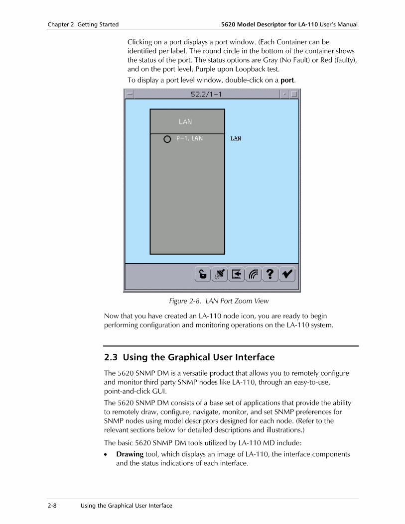
Clicking on a port displays a port window. (Each Container can be identified per label. The round circle in the bottom of the container shows the status of the port. The status options are Gray (No Fault) or Red (faulty), and on the port level, Purple upon Loopback test. To display a port level window, double-click on a port.
Figure 2-8. LAN Port Zoom View
Now that you have created an LA-110 node icon, you are ready to begin performing configuration and monitoring operations on the LA-110 system.
2.3 Using the Graphical User Interface
The 5620 SNMP DM is a versatile product that allows you to remotely configure and monitor third party SNMP nodes like LA-110, through an easy-to-use, point-and-click GUI.
The 5620 SNMP DM consists of a base set of applications that provide the ability to remotely draw, configure, navigate, monitor, and set SNMP preferences for SNMP nodes using model descriptors designed for each node. (Refer to the relevant sections below for detailed descriptions and illustrations.)
The basic 5620 SNMP DM tools utilized by LA-110 MD include:
• Drawing tool, which displays an image of LA-110, the interface components and the status indications of each interface.

5620 Model Descriptor for LA-110 User’s Manual Chapter 2 Getting Started
Using the Graphical User Interface 2-9
• Navigator tool, in which the model descriptors provide the capability of listing the managed objects of LA-110.
• Configuration tool, which provides appropriate tabular or scalar forms to configure node, slot and interface control attributes in LA-110.
• Monitor tool, which provides a mechanism to poll for changes in the attributes of the managed objects.
The LA-110 MD determines the: • GUI labels on the form
• Rules for entering values on the form
• Available options behind the menu items.
The GUI forms support following features: • Standard Text/Data Elements: Edit Box, Combo Box, and Table.
• Standard buttons: Save, Cancel, Close, Refresh, Navigator, Help, and Draw.
Figure 2-9 shows a typical GUI form, the LA-110 Node Navigator (Expanded).
Figure 2-9. LA-110 Navigator
Alarm and Test Indication Alarms and tests are indicated by the color of the frame around the port.

Chapter 2 Getting Started 5620 Model Descriptor for LA-110 User’s Manual
2-10 Using the Graphical User Interface
Card Status (only in 5620 Shelf View)
Card status is indicated by the following colors:
• Gray: Normal
• Red: All the other cases (alarm is present)
Card Status will be determined according to status of the port in this card:
• If the port on a card is Faulty: the card is colored red.
• Else – if the port is faulty: the card is colored gray.
Port Status
Port status is indicated by the following port colors:
• RED: Fault
• GREEN: OK
• PURPLE: Test/Unknown
(Note that port status is Unknown when both the port status color is Purple and there is no loopback test running on the port.
Drawing Tool The 5620 SNMP DM Drawing tool uses data provided by the LA-110 MD to display a graphical representation of the node’s components and subcomponents (i.e. LA-110 front and rear panels as shown in Figure 2-10.
Each Drawing Tool module has toolbar buttons that enable the operator to launch appropriate Configure and Monitor forms for the selected interface.
Context sensitive menus allow you to invoke the Model Descriptor Configuration, Monitor, or other Forms.
To launch the Draw tool:
1. In the 5620 Network map, right-click on an LA-110 Node icon, and select Manage Object.
Draw displays a visual image of the managed device, including its components and their relevant status indications (see Figure 2-10).

5620 Model Descriptor for LA-110 User’s Manual Chapter 2 Getting Started
Using the Graphical User Interface 2-11
Figure 2-10. Draw Tool, LA-110 Front & Rear Panels
2. In the Draw application, select an object, right-click and select the following shortcut menu options: Configure – provides appropriate forms to configure any object attributes
in the managed device.
Monitor – offers a mechanism to monitor and report the status and changes in the attributes of the managed objects, using traps and SNMP queries.
Navigator Tool The 5620 SNMP DM Navigator tool uses the data provided by the LA-110 MD to display the node’s containment hierarchy. An ellipsis (…) indicates a container, which you can double-click to display components (user and network interfaces).
Context sensitive menus allow you to invoke the Model Descriptor Configuration, Monitor, or other Forms.
The Navigate tool provides a Navigator window that presents the components of the LA-110 node in a hierarchical list. Each node can be selected and expanded to view the components of the node. Each object in the hierarchy is a selectable object.
For each of these objects, the Configure and Monitor tools are often available through the Object menu button (or right mouse button click) of the 5620 SNMP DM form.

Chapter 2 Getting Started 5620 Model Descriptor for LA-110 User’s Manual
2-12 Using the Graphical User Interface
To launch the Navigator:
• In the Draw application, click the Navigator button.
As shown in Figure 2-11, the Navigator tool facilitates an auto-discovery block that maps the node, slot and interface into the managed object hierarchy.
Figure 2-11. Navigator Tool (Collapsed upon Launching)
Configuration Tool The Configuration tool allows you to configure the SNMP node attributes.
The LA-110 MD determines the basic attributes on the LA-110 node at the system and port levels.
Monitor Tool Monitor forms are read-only; they allow 5620 SNMP DM users to monitor the node’s objects. The LA-110 MD defines which attributes and statistics you can monitor on the 5620 SNMP DM GUI. Currently, the Monitor tool allows displaying only active alarms.
Rediscover Tool The Rediscover tool is available for a number of components to allow you to explicitly check the population of subcomponents. There is no form associated with this action and the revised component list is shown on the Navigator form.
•
When using the Rediscovery tool, it is not possible to manipulate other components until the process ends.
Status Bar A Status Bar is located on every form (or dialog box) of the LA-110 MD application.
The Status bar displays various error messages, such as "Node not responding’, "General error" etc., and rediscovery indication.
Note
Selecting the System 3-1
Chapter 3 System Configuration and Monitoring This chapter discusses how to configure and monitor the LA-110 system using LA-110 Model Descriptor.
Managing LA-110 includes the following tasks: • Viewing and modifying system information
• Viewing and modifying system parameters
• Viewing and modifying host interface parameters
• Viewing and modifying traffic descriptor settings
• Viewing and modifying ATM to FR IWF settings
• Viewing and modifying the Manager list
• Selecting AAL1
• Viewing ATM to FR IWF Settings
• Viewing and modifying SNMP community parameters
• Viewing and modifying descriptor settings
• Viewing and modifying LA-110 preferences
• Viewing system faults
• Restoring LA-110 configuration to the default settings
• Resetting LA-110 system configuration
• Resetting all statistics.
In the following procedures (and procedures throughout this manual), “right-click” refers to invoking a right mouse click in order to display shortcut menus related to the selected object.
3.1 Selecting the System
Before you can perform system operations, you must first the select the system (i.e. node) in the 5620 SNMP Draw Mode or in the Navigator. (This procedure discusses how to select the system in the LA-110 Node Draw Mode.)
To select the system:
• In the Entire Network map, select an LA-110 Node icon, right-click and select Manage Object.
Note
Chapter 3 System Configuration and Monitoring 5620 Model Descriptor for LA-110 User’s Manual
3-2 Selecting the System
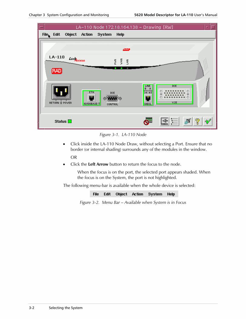
Figure 3-1. LA-110 Node
• Click inside the LA-110 Node Draw, without selecting a Port. Ensure that no border (or internal shading) surrounds any of the modules in the window.
OR
• Click the Left Arrow button to return the focus to the node.
When the focus is on the port, the selected port appears shaded. When the focus is on the System, the port is not highlighted.
The following menu-bar is available when the whole device is selected:
Figure 3-2. Menu Bar – Available when System is in Focus

5620 Model Descriptor for LA-110 User’s Manual Chapter 3 System Configuration and Monitoring
Viewing and Modifying System Information 3-3
3.2 Viewing and Modifying System Information
LA-110 MD allows you to view and modify LA-110 system information.
To view/modify the LA-110 system information:
1. In the LA-110 Node Draw, select the system (as described in Selecting the System), and from the menu bar, select Object > Configure > System Info.
Figure 3-3. System Information Dialog Box
2. Fill in the fields, as described in Table 3-1.

Chapter 3 System Configuration and Monitoring 5620 Model Descriptor for LA-110 User’s Manual
3-4 Viewing and Modifying System Information
3. Click <Save> to save the changes in the NMS. If there is active communication with the Agent, the NMS gets and saves within its database the parameters, as described in Table 3-1. If there is no communication with the Agent, the parameters listed in Table 3-1 are displayed according to the values existing in the NMS database. The NMS will issue warnings about other parameters' values that are not obtainable.
Table 3-1. System Information Parameters
Parameters Possible Values / Remarks
Description Description of the entity, including the full name and version identification of the system's hardware type and operating system.
Read-only
Object ID Object identifier. Identifies the network management subsystem contained in the entity. This value is allocated within the SMI enterprises subtree (1.3.6.1.4.1) and provides an easy and unambiguous means for determining 'what kind of box' is being managed.
Read-only
Name Name of the managed node.
String of up to 36 characters.
By convention, this is the node's product name.
Contact Name of contact person for this managed node, together with information on how to contact this person.
String of up to 32 characters.
Location Physical location of this node.
String of up to 32 characters.
System Up Time
Time since the system was last re-initialized. Format: d: days, hh:mm:ss Read-only
Date & Time The following are the system date and time parameters. When you choose the month, day, and year, and click <Save>, the NMS checks validity of the specified value. If an invalid value is entered, a warning message is issued in the status bar: "Invalid Date" without applying change to the system.
Month January - December
Day 1-31
Year 1970 - 2099
Time Format:
hh:mm:ss
Number of Interfaces
The number of physical and logical interfaces within this node.
Read-only
Number of Connections in Use
The number of physical connections in use.
Read-only
5620 Model Descriptor for LA-110 User’s Manual Chapter 3 System Configuration and Monitoring
Viewing and Modifying System Parameters 3-5
Table 3-1. System Information Parameters (Cont.)
Parameters Possible Values / Remarks
Max Number of Connections
The maximum number of connections.
Read-only
Free Bandwidth (Kbps)
The available bandwidth.
Read-only
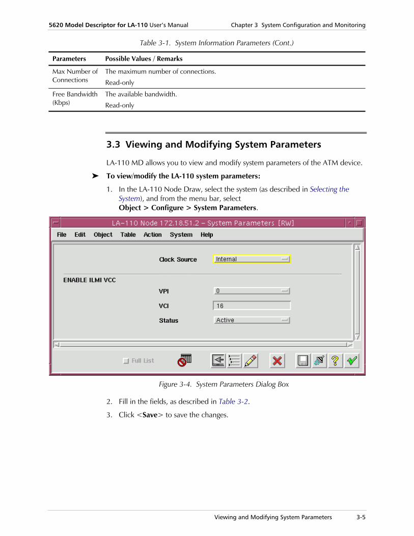
3.3 Viewing and Modifying System Parameters
LA-110 MD allows you to view and modify system parameters of the ATM device.
To view/modify the LA-110 system parameters:
1. In the LA-110 Node Draw, select the system (as described in Selecting the System), and from the menu bar, select Object > Configure > System Parameters.
Figure 3-4. System Parameters Dialog Box
2. Fill in the fields, as described in Table 3-2.
3. Click <Save> to save the changes.

Chapter 3 System Configuration and Monitoring 5620 Model Descriptor for LA-110 User’s Manual
3-6 Viewing and Modifying Host Interface Parameters
Table 3-2. System Parameters
Parameter Valid Ranges/Remarks
Clock Source Indicates which clock is used
Internal, Derived from Main, NTR, Adaptive, Derived from (E1) User
Read-only.
Enable ILMI VCC (If ILMI VCC is disabled, the following fields will be disabled.)
VPI The ILMI VPI
0..31
VCI The ILMI VCI
0..255
Status The ILMI status
Active, Not Active
Note the following:
• ILMI VPI and VCI cannot both be set to zero
• Changing the values of ILMI parameters may disconnect the NMS from the Agent
• ILMI VCC should be different from the management channel.
3.4 Viewing and Modifying Host Interface Parameters
LA-110 MD allows you to determine the IP address of the host, the management channel, and the traffic parameters for this channel.
To view/modify host interface parameters:
1. In the LA-110 Node Draw, select the system (as described in Selecting the System), and from the menu bar, select Object > Configure > Host Interface Parameters.

5620 Model Descriptor for LA-110 User’s Manual Chapter 3 System Configuration and Monitoring
Viewing and Modifying Host Interface Parameters 3-7
Figure 3-5. Host Interface Parameters Dialog Box
2. Fill in the fields, as described in Table 3-3.
3. Click <Save> to save the changes.
Table 3-3. Host Interface Parameters
Parameter Valid Ranges/Remarks
IP The IP address, in the range: 0.0.0.0 to 255.255.255.255
VPI The VPI
0..31
VCI The VCI
0..255
Status The VCC status
Active, Not Active
Continuity Check
The VCC admin status
Off-two-way - down, On-two way – up, On-source, On-sink
Traffic Descriptor
The traffic descriptor
DHCP Client The client action
Disable, Enable
Read-only

Chapter 3 System Configuration and Monitoring 5620 Model Descriptor for LA-110 User’s Manual
3-8 Viewing and Modifying Traffic Descriptor Settings
• Changing the properties of the management channel disconnects the NMS from the Agent.
• SNMP VPI and VCI cannot both be set to zero. • When working with a full bandwidth G.732s or G.732n E1-CES connection, you
may experience problems managing the device when Shaping is set to HW mode. In this case, the workaround is to set the device to work in SW Shaping mode.
3.5 Viewing and Modifying Traffic Descriptor Settings
The Traffic Descriptor window allows you to configure different settings for traffic parameters, and use these settings in multiple connections.
To configure the traffic descriptor:
1. In the LA-110 Node Draw, select the system (as described in Selecting the System), and from the menu bar, select Object > Configure > Traffic Descriptor.
Figure 3-6. Traffic Descriptor
2. Fill in the fields, as described in Table 3-4.
Table 3-4. Traffic Descriptor Table Parameters
Parameter Valid Ranges/Remarks
Traffic Descriptor Table
Index 1-200
Read-only
When adding a row, this parameter is read-write.
Notes
5620 Model Descriptor for LA-110 User’s Manual Chapter 3 System Configuration and Monitoring
Viewing and Modifying Traffic Descriptor Settings 3-9
Table 3-4. Traffic Descriptor Table Parameters (Cont.)
Parameter Valid Ranges/Remarks
Type The ATM traffic descriptor type. The number of parameters and their meaning depends on the TD type.
UBR, UBR+, CBR, VBR
Read-only
PCR[0+1] (cell/sec)
Peak Cell Rate. The maximum rate of cells accepted from the user
79…5452
SCR[0+1] (cell/sec)
Sustainable Cell Rate. The long-term average cell rate provided by the user.
Relevant only to VBR mode
79…5452
MBS[0+1] (cells) Maximum Burst Size. The maximum number of cells allowed in a single burst. Longer bursts may be discarded.
Relevant only to VBR mode
1…10 (default)…999
MDCR (cell/sec) Minimum Desired Cell Rate.
Relevant only to UBR+ mode
1…200 (default)…5452
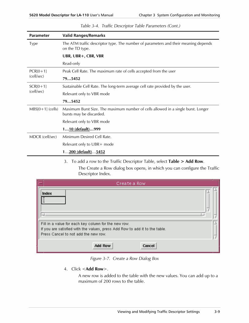
3. To add a row to the Traffic Descriptor Table, select Table > Add Row. The Create a Row dialog box opens, in which you can configure the Traffic Descriptor Index.
Figure 3-7. Create a Row Dialog Box
4. Click <Add Row>. A new row is added to the table with the new values. You can add up to a maximum of 200 rows to the table.

Chapter 3 System Configuration and Monitoring 5620 Model Descriptor for LA-110 User’s Manual
3-10 Viewing and Modifying Traffic Descriptor Settings
5. To delete a row from the table, select a row and click <Delete Row>. A confirmation box opens, prompting you to confirm the deletion. Click <Yes> to delete the selected row or click <No> to cancel. If the row status is active (used by a connection), you cannot delete the row, and a corresponding failure message appears on the status bar: "Remove Fail – Traffic Descriptor is Active".
6. Click <Save> to save the changes.
• The traffic descriptor cannot be changed after it is created. • The minimum PCR value is 79.
Table 3-5. Add/Change Traffic Descriptor Parameters
Parameter Valid Ranges/Remarks
Type The ATM traffic descriptor type. The number of parameters and their meaning depends on the TD type.
Value of the traffic descriptor that applies to Index.
UBR: No traffic descriptor
UBR+: No Clp, No tagging MCR
CBR: No Clp, No SCR
VBR: No ClpScr
Read-only
Traffic Descriptor Parameters
Dependent on the type select, and on the WAN physical line, as described in the following table.
Table 3-6. Traffic Descriptor Types, Dependent on Type Selected and WAN Physical Line
Type UBR UBR+ CBR VBR
ATM Traffic Descriptor type
No Traffic Descriptor
ATM CLp, No tagging Mcr
No CLp No Scr No CLp Scr
PCR[0+1] (cell/sec) 79…Max. Line rate, according to device Main Link (WAN) type (default value)
79…Max. Line rate, according to device Main Link (WAN) type (default value)
79 (default value)…Max. Line rate, according to device Main Link (WAN) type
79…Max. Line rate, according to device Main Link (WAN) type (default value)
Notes
5620 Model Descriptor for LA-110 User’s Manual Chapter 3 System Configuration and Monitoring
Viewing and Modifying the Manager List 3-11
Table 3-6. Traffic Descriptor Types, Dependent on Type Selected and WAN Physical Line (Cont.)
Type UBR UBR+ CBR VBR
SCR[0+1] (cell/sec) -- -- -- 79 (default value)…5453
MBS[0+1] (cells) -- -- -- 1…999 (where 10 is default value)
MDCR (cell/sec) -- 1…SHDSL 2W: 5453…(or SHDSL 4W: 10,868)
-- --
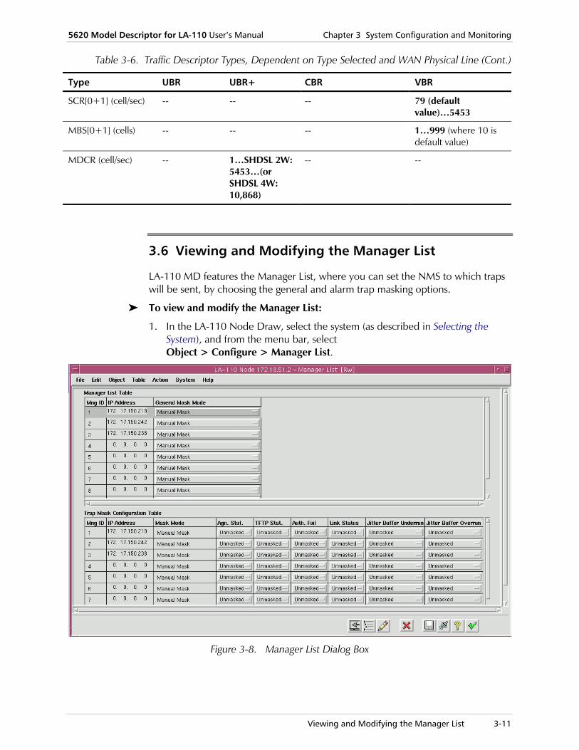
3.6 Viewing and Modifying the Manager List
LA-110 MD features the Manager List, where you can set the NMS to which traps will be sent, by choosing the general and alarm trap masking options.
To view and modify the Manager List:
1. In the LA-110 Node Draw, select the system (as described in Selecting the System), and from the menu bar, select Object > Configure > Manager List.
Figure 3-8. Manager List Dialog Box

Chapter 3 System Configuration and Monitoring 5620 Model Descriptor for LA-110 User’s Manual
3-12 Viewing and Modifying the Manager List
2. In the Manager List Table (located at the top), select the general mask modes (per row entry), by selecting the relevant options from the drop-down lists. The options include: Manual Mask, Mask All Traps, Mask Only Alarm Traps, Unmask Alarm Traps.
3. In the Trap Mask Configuration Table, you can manually select the masking settings per specified traps. In the relevant Traps fields, from the drop-down lists, choose <Masked> or <Unmasked>. (The default trap value is "Unmasked").
4. View the fields, as described in Table 3-7.
5. Click <Save> to save the changes.
The only changeable parameters in the Manager List are the Masking Traps.
Table 3-7. Manager List Parameters
Parameter Valid Ranges/Remarks
Manager List Table
Manager ID The manager ID.
1…10
Read-only
IP Address When adding a row, this parameter is read-write and has a range of 0.0.0.0 to 255.255.255.255
Read-only
General Mask Mode
The general mask mode
• Manual Mask: The traps in the Trap Masking Mode Table can be configured manually
• Mask All Traps: All the traps in the Trap Masking Mode Table will be masked
• Mask Only Alarm Traps: Only the Alarm Traps in the Trap Masking Mode Table will be masked
• Unmask Alarm Traps: The Alarm Traps in the Trap Masking Mode Table will be unmasked
Trap Masking Configuration Table
Agn Stat. Affects the agnStatusChangeTrap
Unmasked, Masked
TFTP Stat. Affects the tftpStatusChangeTrap
Unmasked, Masked
Auth. Fail Affects the authenticationFailure trap
Unmasked, Masked
Note

5620 Model Descriptor for LA-110 User’s Manual Chapter 3 System Configuration and Monitoring
Viewing and Modifying the Manager List 3-13
Table 3-7. Manager List Parameters (Cont.)
Parameter Valid Ranges/Remarks
Link Status Indictates whether the linkDown or linkUp.traps should be generated for this interface.
Unmasked, Masked
Jitter Buffer Underrun
Affects the atmSuJitterBufferUnderrun trap
Unmasked, Masked
Jitter Buffer Overrun
Affects the atmSuJitterBufferOverrun trapUnmasked, Masked
No Buffer to Network
Affects the atmSuAgnNoBuffertoNetwork trap
Unmasked, Masked
Sync on Low Rate
Affects the agnActualLowRate trap
Unmasked, Masked
DB Checksum Error
Affects the agnConfigDBChecksumError trap
Unmasked, Masked
Param. Change During Upgrade
Affects the agnParametersValueChanged trap
Unmasked, Masked
Alr. Buff. Overflow
Affects the agnAlarmBufferOverflow trap
Unmasked, Masked
Alr. Buff. Clear Affects the agnAlarmBufferClear trap
Unmasked, Masked
BW Exc. Alloc Affects the atmAceUnavailableBw trap
Unmasked, Masked
LCD Affects the atmAceAlarmLCD trap
Unmasked, Masked
VC Cont. Loss Affects the atmAceAlarmVcContinuityLoss trap
Unmasked, Masked
VC Rx AIS Affects the atmAceAlarmVcAISReception trap
Unmasked, Masked
VC Rx RDI Affects the atmAceAlarmVcRDIReception trap
Unmasked, Masked
VC OAM LB Fail.
Affects the atmAceAlarmVcLoopback trap
Unmasked, Masked
SHDSL Driver Mismatch
Affects the gnDriverSwMismatch trap
Unmasked, Masked
SHDSL EOC LB Affects the radHdsl2ShdslLoopBack trap
Unmasked, Masked

Chapter 3 System Configuration and Monitoring 5620 Model Descriptor for LA-110 User’s Manual
3-14 Viewing and Modifying the Manager List
Table 3-7. Manager List Parameters (Cont.)
Parameter Valid Ranges/Remarks
Data LLB Affects the atmSuDataLocalLoopback trap
Unmasked, Masked
Data RLB Affects the atmSuDataRemoteLoopback trap
Unmasked, Masked
Manager List Traps
E1 traps exists only if CES- E1 port exists on the device
AIS Affects the ds1Ais trap
Unmasked, Masked
BPV Error Affects the ds1BpvError trap
Unmasked, Masked
CRC4 Error Affects the ds1Crc4Error trap
Unmasked, Masked
Frame Slip Affects the ds1LinkFrameSlip trap
Unmasked, Masked
E1 Loc. MF Alr. Affects the ds1LocalMultiframeAlarm trap
Unmasked, Masked
E1 Rem. MF Alr. Affects the ds1RemoteMultiframeAlarm trap
Unmasked, Masked
E1 Loc. Sync Loss
Affects the ds1LocalSyncLoss trap
Unmasked, Masked
E1 Rem. Sync Loss
Affects the ds1RemoteSyncLoss trap
Unmasked, Masked
E1 AIS Sync Loss Affects the ds1AisSyncLoss trap
Unmasked, Masked
E1 User RLB Affects the ds1RemoteLoop trap
Unmasked, Masked
E1 User LLB Affects the ds1LocalLoop trap
Unmasked, Masked
Signal Loss Affects the ds1SignalLoss trap
Unmasked, Masked
E1 Ex. BPV Erro Affects the ds1ExcessiveBpv trap
Unmasked, Masked
CRC4 Ex. Error Affects the ds1ExcessiveCrc4Error trap
Unmasked, Masked

5620 Model Descriptor for LA-110 User’s Manual Chapter 3 System Configuration and Monitoring
Selecting AAL1 3-15
Table 3-7. Manager List Parameters (Cont.)
Parameter Valid Ranges/Remarks
Error Ex. Ratio Affects the ds1ExcessiveErrorRatio trap
Unmasked, Masked
Frame Ex. Sli Affects the ds1ExcessiveFrameSlip trap
Unmasked, Masked
E1 Ex. Loc. MF Alr.
Affects the ds1ExcessiveLocalMfAlarm trap
Unmasked, Masked
E1 Ex. Rem. MF Alr.
Affects the ds1ExcessiveRemoteMfAlarm trap
Unmasked, Masked
E1 Ex. Loc. Sync Loss
Affects the ds1ExcessiveLocalSyncLoss trap
Unmasked, Masked
E1 Ex. Rem. Sync Loss
Affects the ds1ExcessiveRemoteSyncLoss trap
Unmasked, Masked
3.7 Selecting AAL1
The AAL1 mode selection option is only available if the system is set to AAL2 mode.
To view and modify the Manager List:
1. In the LA-110 Node Draw, select the system (as described in Selecting the System), and from the menu bar, select Object > Configure > AAL1 Selection.
Figure 3-9. AAL1 Dialog Box
2. From the Selected Layer drop-down list, choose <AAL1>.
3. Click <Save> to save the changes.
Note

Chapter 3 System Configuration and Monitoring 5620 Model Descriptor for LA-110 User’s Manual
3-16 Viewing ATM to FR IWF Settings
3.8 Viewing ATM to FR IWF Settings
You can select the Frame Relay interworking mode: network interworking per FRF.5 or service interworking per FRF.8.
• The network interworking mode, defined in FRF.5, is used to interconnect Frame Relay equipment through an ATM network. You can configure the way the Frame Relay traffic control parameters are converted to the cell loss priority (CLP) indicator used on the ATM connection, and back.
• Service interworking mode, defined in FRF.8, is used to interconnect an equipment unit with Frame Relay interface to an equipment unit with ATM interface.
To view the ATM to FR IWF Table:
1. In the LA-110 Node Draw, select the system (as described in Selecting the System), and from the menu bar, select Object > Configure > ATM to FR IWF Table.
Figure 3-10. ATM to FR IWF Table
2. View the fields, as described in Table 3-8.
5620 Model Descriptor for LA-110 User’s Manual Chapter 3 System Configuration and Monitoring
Viewing ATM to FR IWF Settings 3-17
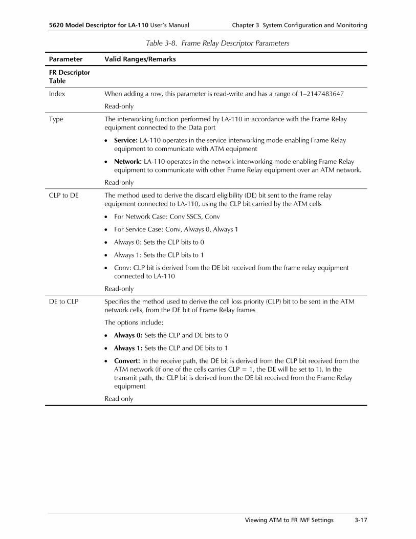
Table 3-8. Frame Relay Descriptor Parameters
Parameter Valid Ranges/Remarks
FR Descriptor Table
Index When adding a row, this parameter is read-write and has a range of 1–2147483647
Read-only
Type The interworking function performed by LA-110 in accordance with the Frame Relay equipment connected to the Data port
• Service: LA-110 operates in the service interworking mode enabling Frame Relay equipment to communicate with ATM equipment
• Network: LA-110 operates in the network interworking mode enabling Frame Relay equipment to communicate with other Frame Relay equipment over an ATM network.
Read-only
CLP to DE The method used to derive the discard eligibility (DE) bit sent to the frame relay equipment connected to LA-110, using the CLP bit carried by the ATM cells
• For Network Case: Conv SSCS, Conv
• For Service Case: Conv, Always 0, Always 1
• Always 0: Sets the CLP bits to 0
• Always 1: Sets the CLP bits to 1
• Conv: CLP bit is derived from the DE bit received from the frame relay equipment connected to LA-110
Read-only
DE to CLP Specifies the method used to derive the cell loss priority (CLP) bit to be sent in the ATM network cells, from the DE bit of Frame Relay frames
The options include:
• Always 0: Sets the CLP and DE bits to 0
• Always 1: Sets the CLP and DE bits to 1
• Convert: In the receive path, the DE bit is derived from the CLP bit received from the ATM network (if one of the cells carries CLP = 1, the DE will be set to 1). In the transmit path, the CLP bit is derived from the DE bit received from the Frame Relay equipment
Read only

Chapter 3 System Configuration and Monitoring 5620 Model Descriptor for LA-110 User’s Manual
3-18 Viewing and Modifying SNMP Community
Table 3-8. Frame Relay Descriptor Parameters (Cont.)
Parameter Valid Ranges/Remarks
FECN to EFCI Specifies the method used to convert the forward explicit congestion notification (FECN) information to the congestion indication (CI) bit, or the explicit forward congestion indication (EFCI) bit, to be inserted in the ATM cells
• Always 0: Ignores the FECN bit received from the Frame Relay equipment connected to the data port, and always set the EFCI bit to 0
• Conv: In the receive path, the EFCI/CI bit is derived from the received FECN bit
Read only
Upper Layer Mapping
Protocol handling method
• Transparent: Transparently transfers encapsulation header
• Translation: Converts the encapsulation header from RFC 1490 ( FR ) to RFC 1483 (ATM)
Read-only
3.9 Viewing and Modifying SNMP Community
SNMP delimits management domains by defining communities. Each community is identified by a name, which is an alphanumeric string of up to 255 characters defined by the user.
The 5620 Model Descriptor for LA-110 SNMP agent defines strings of up to 10 characters (case sensitive, numeric and alphabetical). Any SNMP entity (both managed entities and management stations) is assigned a community name by its user. In parallel, the user defines a list of the communities for each SNMP entity that are authorized to communicate with the entity, and the access rights associated with each community (this is the SNMP community name table of the entity). In general, SNMP agents support two types of access rights: • Read: The SNMP agent accepts and processes only SNMP getRequest and
getNextRequest PDUs with matching community names.
• Write: The SNMP agent accepts and processes all the SNMP commands received from a management station with matching community names.
To view and modify SNMP community:
1. In the LA-110 Node Draw, select the system (as described in Selecting the System), and from the menu bar, select Object > Configure > SNMP Community.

5620 Model Descriptor for LA-110 User’s Manual Chapter 3 System Configuration and Monitoring
Viewing and Modifying Descriptor Settings 3-19
Figure 3-11. SNMP Community Dialog Box
2. Fill in the fields, as described in Table 3-9.
3. Click <Save> to save the changes.
Table 3-9. SNMP Community Parameters
Parameters Possible Values / Remarks
read Community
The community string sent with a get/getNext request pdu from the NMS
Default value: public
write Community
The community string sent with a set request pdu from the NMS
Default value: private
3.10 Viewing and Modifying Descriptor Settings
LA-110 MD allows you to view the current MD version and modify descriptor settings for debugging purposes.
To view and modify descriptor settings:
1. In the LA-110 Node Draw, select the system (as described in Selecting the System), and from the menu bar, select Object > Configure > Descriptor Settings.

Chapter 3 System Configuration and Monitoring 5620 Model Descriptor for LA-110 User’s Manual
3-20 Viewing and Modifying LA-110 Preferences
Figure 3-12. Descriptor Settings Dialog Box
2. Fill in the fields, as described in Table 3-10.
3. Click <Save> to save the changes.
Table 3-10. Descriptor Settings Parameters
Parameters Possible Values / Remarks
MD Version The MD version
String
Read-only
Output Log The output log, allows you to determine whether actions will be recorded on a log file. The log file is created in /opt/netmgt/nodemgr/bin/log and is named NodeIPLA110.log.
No, Yes (File), Default (Transcript)
3.11 Viewing and Modifying LA-110 Preferences
This section explains how to display and modify the LA-110 unit preferences.
Viewing and Modifying System Preferences At the system level you can specify a path to the Web browser to be used for the online help file display.
To view and modify the system preferences:
1. In the LA-110 Node Draw, select the system (as described in Selecting the System), and from the menu bar, select Object > Configure > Preferences.

5620 Model Descriptor for LA-110 User’s Manual Chapter 3 System Configuration and Monitoring
Managing System Faults 3-21
Figure 3-13. System Preferences
2. Enter the Web browser path. The default Web browser path is: /usr/dt/bin/netscape.
If Mozilla is used, then change to the path where Mozilla is usually installed:
/usr/local/bin/mozilla
3. Enter the help file path. The default help file path is: /opt/netmgt/documentation/RAD/LA110/LA110_R2_Descriptor_Help.htm
The title bar at the top of the Configure Preferences window will show the System Name, the IP address of the node, and the name of the form as follows: LA-110 - IP Address - Configure Preferences
4. Click <Save> to save the changes.
3.12 Managing System Faults
This section discusses how to monitor system alarms, using LA-110 MD.
Viewing Active Alarms LA-110 MD allows you to monitor active alarms in the LA-110 node.
To view active alarms in the LA-110 node:
• In the LA-110 Node Draw, select the system (as described in Selecting the System), and from the menu bar, select Monitor > All Active Alarms
A Monitor form appears, displaying currently active alarms as shown in Figure 3-14.

Chapter 3 System Configuration and Monitoring 5620 Model Descriptor for LA-110 User’s Manual
3-22 Managing System Faults
Figure 3-14. All Active Alarm List
Viewing Alarm History in the System Log Buffer LA-110 MD provides a Log Buffer in which you can debug and trace problems.
This section discusses how to use LA-110 MD to view a list of the system alarms stored in the Agent Log Buffer.
To view alarm history log in the Log Buffer:
1. In the LA-110 Node Draw, select the system, (as described in Selecting the System), and from the menu bar, select Object > Configure > History Log List.

5620 Model Descriptor for LA-110 User’s Manual Chapter 3 System Configuration and Monitoring
Managing System Faults 3-23
Figure 3-15. System Log Buffer Dialog Box
2. View the fields, as described in Table 3-11.
3. Click <Refresh> to refresh the data table.
4. Click <Close> to close the System Log Buffer form.

Chapter 3 System Configuration and Monitoring 5620 Model Descriptor for LA-110 User’s Manual
3-24 Managing System Faults
Table 3-11. System Log Buffer Parameters
Parameters Possible Values / Remarks
System Log Table
Number The row's sequence number.
Read-only
Interface The inteface.
VPI Appears when relevant
Read-only
VCI Appears when relevant
Read-only
Description Description of the event or alarm
Status The system history alarm status
On, Off, Event
Date & Time The date and time the history alarm occurred.
String: YYY-MM-DD, hh:mm:ss
Clearing the History Log This section discusses how to use LA-110 MD to clear the history log in the log buffer of the LA-110 node.
To clear the history log:
1. In the LA-110 Node Draw, select the system (as described in Selecting the System), and from the menu bar, select Action > Perform Action > Clear History Log.
Figure 3-16. Clear History Log Confirmation Dialog Box
2. Click <Yes> to clear all the entries in the Log Buffer. The Agent resets the variable to Off after clearing the Log Buffer.
5620 Model Descriptor for LA-110 User’s Manual Chapter 3 System Configuration and Monitoring
Resetting System Configuration 3-25
3.13 Resetting System Configuration
The LA-110 MD allows you to reset the LA-110 device.
Resetting the LA-110 device includes the following tasks:
• Restoring the default configuration
• Resetting the system.
Restoring the Default Configuration To restore the default configuration:
1. In the LA-110 Node Draw, select the system, (as described in Selecting the System), and from the menu bar, select Action > Perform Action > Reset Configuration.
A confirmation box opens, displaying the following message: "Resetting Configuration. Operation will cause agent disconnection. Do you wish to continue?"
2. Click <Yes> to confirm the reset.
Resetting the System LA-110 MD allows you to reset the device.
The reset operation implements any changes that were made and updates the agent’s configuration.
To reset the system hardware:
1. In the LA-110 Node Draw, select the system, (as described in Selecting the System), and from the menu bar, select Action > Perform Action > Reset HW.
A confirmation box opens, displaying the following message: "Resetting the device. Operation may change system configuration. Do you wish to continue?"
2. Click <Yes> to reset the system. Unit reset is performed.
Note

Chapter 3 System Configuration and Monitoring 5620 Model Descriptor for LA-110 User’s Manual
3-26 Resetting System Configuration
Resetting All Statistics LA-110 MD allows you to reset all of the system statistics. It comes in handy especially in the case of running statistics counters forms.
To reset system statistics:
1. In the LA-110 Node Draw, select the system, (as described in Selecting the System), and from the menu bar, select Action > Perform Action > Reset All Statistics.
A confirmation box opens, displaying the following message: “Resetting all statistics. All counters are set to zero. Do you wish to continue?"
2. Click <Yes> to reset the statistics.
Viewing Online Help For further referencing, an online help feature is available for researching questions quickly, and learning more about operating LA-110. The default help file path is: /opt/netmgt/documentation/RAD/LA110/LA110_R2_Descriptor_Help.htm.
To view online help topics:
1. In the LA-110 Node Draw, select the system, (as described in Selecting the System), and from the menu bar, select Action > Perform Action > Online Help.
A confirmation box opens, displaying the following message: “Opening Help files. Do you wish to continue?"
2. Click <Yes> to open the help file. The default Web browser with the default help file path opens.
Selecting Ports 4-1
Chapter 4 Port Configuration and Monitoring This chapter discusses how to configure and monitor LA-110 ports using LA-110 Model Descriptor.
Managing ports includes the following tasks: • Selecting ports
• Performing port operations
• Viewing port parameters
• Configuring ports
• Monitoring port performance.
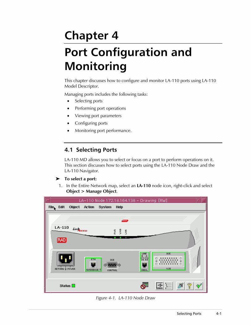
4.1 Selecting Ports
LA-110 MD allows you to select or focus on a port to perform operations on it. This section discusses how to select ports using the LA-110 Node Draw and the LA-110 Navigator.
To select a port: 1. In the Entire Network map, select an LA-110 node icon, right-click and select
Object > Manage Object.
Figure 4-1. LA-110 Node Draw
Chapter 4 Port Configuration and Monitoring 5620 Model Descriptor for LA-110 User’s Manual
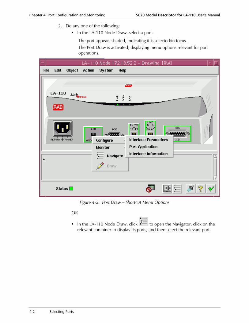
4-2 Selecting Ports
2. Do any one of the following: In the LA-110 Node Draw, select a port.
The port appears shaded, indicating it is selected/in focus. The Port Draw is activated, displaying menu options relevant for port operations.
Figure 4-2. Port Draw – Shortcut Menu Options
OR
In the LA-110 Node Draw, click to open the Navigator, click on the relevant container to display its ports, and then select the relevant port.

5620 Model Descriptor for LA-110 User’s Manual Chapter 4 Port Configuration and Monitoring
Viewing Port Parameters 4-3
Figure 4-3. Navigator showing Ports
4.2 Performing Port Operations
To perform operations on ports:
• In the Port Draw or Navigator, right-click on the selected port, and choose any of the shortcut menu options.
4.3 Viewing Port Parameters
When focusing on a LA-110 port, you can view its parameters. (Instructions for configuring the specific LA-110 ports appear in the following sections in this chapter.)
To view port parameters:
1. In the LA-110 Node Draw, focus on the desired unit port.
2. Right-click on the port and select the relevant shortcut menu options: For the Data port,
select Configure > FR Interface > Interface Parameters
For the SHDSL port, select Configure > Physical Layer or ATM Layer > Parameters
For the E1 CES port, select Configure > Parameters
For the LAN port, select Configure > Interface Parameters

Chapter 4 Port Configuration and Monitoring 5620 Model Descriptor for LA-110 User’s Manual
4-4 Configuring Ports
Figure 4-4. LAN Port Parameters
To revert back to the system level – Node Draw, click .
4.4 Configuring Ports
The following sections discuss how to configure LA-110 (ATM, Ethernet, CES, and Data) ports using the Node Draw. (Alternatively, you can access ports in the Navigator by double-clicking on Shelf > Slot containers.)
Topics include:
• Data (FR/AAL1 Stream) port configuration
• LAN port configuration – and Bridge port configuration
• SHDSL port configuration
• CES E1 port configuration.
Note

5620 Model Descriptor for LA-110 User’s Manual Chapter 4 Port Configuration and Monitoring
Data Port Configuration 4-5
4.5 Data Port Configuration
The data port is a synchronous serial port with a DCE interface. The interface type is user-configurable: RS-530, V.35, V.36 or X.21. (The physical adaptation is made by adapter cables.) The data port can be configured to operate at rates of n × 64 kbps in the range of 64 to 2048 kbps.
The service type is user-configurable:
• Transparent transmission of serial data stream
• Frame Relay service for connection to Frame Relay equipment. Up to 8 DLCIs are supported. The user can select between service interworking per FRF.8 and network interworking per FRF.5.
Basic tasks include viewing and configuring:
• Data port application
• Data FR application mode
• AAL1 Stream application mode.
Data Port Application The Data port application determines the operation mode of the port (either Frame Relay or AAL1 Stream).
To configure the Data FR port application:
1. In the LA-110 Node Draw, select the Data FR port, right-click and select Configure > Data Port Application.
Figure 4-5. Data Port Application (Frame Relay Mode)
2. Fill in the fields, as described in Table 4-1.
3. Click <Save> to save the changes. If the data application was changed, a confirmation message dialog appears: “Data Port application change requires device Reset. Operation will DELETE AAL1/FR Connections and RESET the Device. Do You Wish to Continue?” Click <Yes> to confirm.

Chapter 4 Port Configuration and Monitoring 5620 Model Descriptor for LA-110 User’s Manual
4-6 Data Port Configuration
Table 4-1. Data Port Application Parameters
Parameter Remarks
Port The selected port
Read-only
Port Application The protocol application which runs above the physical port.
Frame Relay, AAL1 Stream
Data FR Application Mode When the LA-110 Data port is configured to support Frame Relay services, the traffic is carried over AAL5, per the selected ATM service category. You can define the desired ATM connection parameters in accordance with the application requirements.).
The number of supported DLCIs (Data Link Connection Identifiers) is 16, and the allowed range is 16 through 991.
Basic tasks include viewing and configuring: Interface information
Interface parameters
VC signaling information
Loopback testing.
Interface Information
To view FR interface information:
• In the LA-110 Node Draw, select the Data FR port, right-click and select Configure > FR Interface > Interface Info.

5620 Model Descriptor for LA-110 User’s Manual Chapter 4 Port Configuration and Monitoring
Data Port Configuration 4-7
Figure 4-6. FR Interface Information
Table 4-2. FR Interface Information Parameters
Parameter Remarks
Port The selected port
Read-only
Type The protocol application which runs above the physical port.
Frame Relay
Read-only
Interface The interface.
X.21, V.35, V.36
Read-only
Data Mode This attribute indicates the port mode of sampling physical data.
NRZ1, NRZ
Read-only

Chapter 4 Port Configuration and Monitoring 5620 Model Descriptor for LA-110 User’s Manual
4-8 Data Port Configuration
Table 4-2. FR Interface Information Parameters (Cont.)
Parameter Remarks
Clock Mode Indicates the clock used for synchronization for the data port.
DCE
Read-only
Oper. Status The actual link status.
Up, Down
Read-only
MTU (byte) The size of the largest packet which can be sent/received on the interface, specified in octets. For interfaces that are used for transmitting network datagrams, this is the size of the largest network datagram that can be sent on the interface
Integer
Read-only
Last Change This field indicates the time of the last change on the port.
Read-only
Interface Parameters
To configure FR interface parameters:
1. In the LA-110 Node Draw, select the Data FR port, right-click and select Configure > FR Interface > Interface Parameters.

5620 Model Descriptor for LA-110 User’s Manual Chapter 4 Port Configuration and Monitoring
Data Port Configuration 4-9
Figure 4-7. FR Interface Parameters
2. Fill in the fields, as described in Table 4-3.
3. Click <Save> to save the changes. If the data rate was changed, a confirmation message dialog appears: “Data Rate change requires device reset. Operation will RESET the Device. Do You Wish to Continue?” Click <Yes> to confirm. If the CRC value was changed, a confirmation message dialog appears: “CRC change requires device reset. Operation will RESET the Device. Do You Wish to Continue?” Click <Yes> to confirm.
Table 4-3. FR Interface Parameters
Parameter Remarks
Port The selected port
Read-only
Type The protocol application which runs above the physical port.
Frame Relay
Read-only

Chapter 4 Port Configuration and Monitoring 5620 Model Descriptor for LA-110 User’s Manual
4-10 Data Port Configuration
Table 4-3. FR Interface Parameters (Cont.)
Parameter Remarks
Physical
Data Rate (Kbps) The operation rate of the port in kbps.
64, 128, 256...1792 Kbps (in intervals of 64 kbps)
CRC Specifies the CRC polynomial to be used for error detection by the data port.
CRC 16, CRC 32
Clock Polarity Specifies the relative clock polarity, for compatibility with user-equipment interface characteristics
• Normal: Clock falling edge occurs in the middle of the bit interval
• Inverted: Clock rising edge occurs in the middle of the bit interval
Signaling Protocol
Specifies the Frame Relay link control protocol to be used on the data port.
Note: The protocol must match the protocol used by the equipment connected to the data port
If the CLLM status is active:
• No protocol is to be used
• CCITTQ933A: ITU-T Rec. Q.933, Annex A
• ANSIT1617D: ANSI T1.617, Annex D
• LMI specification
Signaling Procedure
The Local In-Channel Signaling Procedure that is used.
• Not Applicable: if the protocol is None
• User to Net (Network side)
• User to Net (User side)
• Bidirectional
CLLM Status Indicates if the configuration supports CLLM (Consolidated Link Layer Management).
• Active
• Not Active: if the protocol is IMI
VC Signaling Information
This dialog is relevant only to DATA-FR port application when the Signaling Protocol is other than none.
To view VC signaling information:
• In the LA-110 Node Draw, select the Data FR port, right-click and select Configure > FR Interface > VC Signaling Information.
Note

5620 Model Descriptor for LA-110 User’s Manual Chapter 4 Port Configuration and Monitoring
Data Port Configuration 4-11
Figure 4-8. FR Interface VC Signaling Information
Table 4-4. FR Interface VC Signaling Information Parameters
Parameter Remarks
Port The selected port
Read-only
Type The protocol application which runs above the physical port.
Frame Relay
Read-only
Note: The following fields, reflecting Network and User-Sides, appear according to the setting of the VC Signaling Procedure parameter. The NMS is capable of supporting either side alone or both sides (Network and User) concurrently. Only the supported side(s) will be displayed.
Network-Side
N392 Error Threshold
1..10
Read-only
N393 Monitored Events
1..10
Read-only
T392 Link Integrity Polling Timer
5..30
Read-only
Chapter 4 Port Configuration and Monitoring 5620 Model Descriptor for LA-110 User’s Manual
4-12 Data Port Configuration
Table 4-4. FR Interface VC Signaling Information Parameters (Cont.)
Parameter Remarks
User-Side
N391 Polling Cycle
1..255
Read-only
N392 Polling Cycle
1..10
Read-only
N393 Polling Cycle
1..10
Read-only
T391 Link Integrity Polling Timer
5..30
Read-only
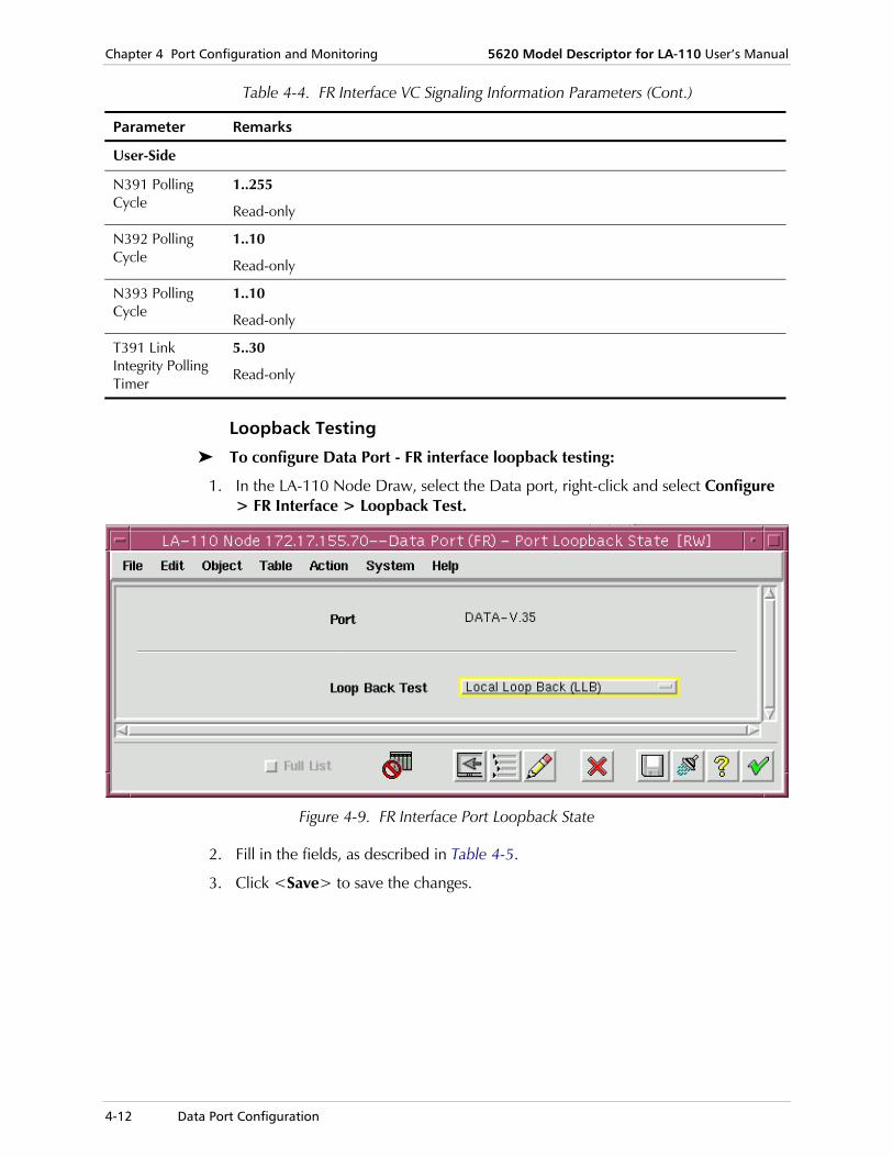
Loopback Testing
To configure Data Port - FR interface loopback testing:
1. In the LA-110 Node Draw, select the Data port, right-click and select Configure > FR Interface > Loopback Test.
Figure 4-9. FR Interface Port Loopback State
2. Fill in the fields, as described in Table 4-5.
3. Click <Save> to save the changes.

5620 Model Descriptor for LA-110 User’s Manual Chapter 4 Port Configuration and Monitoring
Data Port Configuration 4-13
Table 4-5. Data Port - FR Interface Loopback State Parameters
Parameter Remarks
Port The selected port
Read-only
Loopback Test Activates a loopback test on the specified port
• Local Loopback (LLB): Can be used to check the source of a certain problem. Activates the local loopback on the local data port. Checks that the user's equipment receives its own signal while the loopback is connected. If it does, the problem is external.
• Remote Loopback (RLB): Can be used to check the source of a certain problem. For example, if there is certain alarm on a port, and if after activating the RLB the alarm disappears, then the problem is external.
• None: No Test.
AAL1 Stream Application Mode In this application, the data stream at the selected data rate (n kbps) is 64׳transferred transparently. Therefore, the AAL1 stream mode supports any Layer 2 protocol and only one connection can be defined on the port.
Before you can begin configuring the Data Port - AAL1 Stream, you must first configure the Data port application.
To configure the Data port application as AAL1 Stream mode:
1. In the LA-110 Node Draw, select the Data port, right-click and select Configure > Data Port Application.
Figure 4-10. Data Port Application (AAL1 Stream Mode)
2. In the Port Application field, select <AAL1 Stream> to set the mode.

Chapter 4 Port Configuration and Monitoring 5620 Model Descriptor for LA-110 User’s Manual
4-14 Data Port Configuration
3. Click <Save> to save the changes. If the data application was changed, a confirmation message dialog appears: “Data Port application change requires device Reset. Operation will DELETE AAL1/FR Connections and RESET the Device. Do You Wish to Continue?” Click <Yes> to confirm.
Basic tasks for AAL1 Stream application mode include viewing and configuring: Interface information
Interface parameters
Loopback testing.
Interface Information
To view AAL1 Stream interface information:
• In the LA-110 Node Draw, select the Data port, right-click and select Configure > AAL1 Stream Interface > Interface Info.
Figure 4-11. AAL1 Interface Information

5620 Model Descriptor for LA-110 User’s Manual Chapter 4 Port Configuration and Monitoring
Data Port Configuration 4-15
Table 4-6. AAL1 Stream Interface Information Parameters
Parameter Remarks
Port The selected port
Read-only
Type The protocol application which runs above the physical port.
AAL1 Stream
Read-only
Interface The interface type.
X.21, V.35, V.36
Read-only
Data Mode The data mode.
NRZ1, NRZ
Read-only
Oper. Status The actual link status.
Up, Down
Read-only
C-Circuit N/A Not Active, Active
Read-only
I-Circuit N/A, Not Active, Active
Read-only
Last Change This field indicates the time of the last change on the port.
Read-only
Interface Parameters
To configure AAL1 Stream interface parameters:
1. In the LA-110 Node Draw, select the Data port, right-click and select Configure > AAL1 Stream Interface > Interface Parameters.
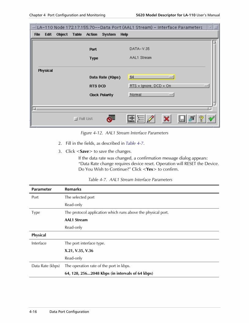
Chapter 4 Port Configuration and Monitoring 5620 Model Descriptor for LA-110 User’s Manual
4-16 Data Port Configuration
Figure 4-12. AAL1 Stream Interface Parameters
2. Fill in the fields, as described in Table 4-7.
3. Click <Save> to save the changes. If the data rate was changed, a confirmation message dialog appears: “Data Rate change requires device reset. Operation will RESET the Device. Do You Wish to Continue?” Click <Yes> to confirm.
Table 4-7. AAL1 Stream Interface Parameters
Parameter Remarks
Port The selected port
Read-only
Type The protocol application which runs above the physical port.
AAL1 Stream
Read-only
Physical
Interface The port interface type.
X.21, V.35, V.36
Read-only
Data Rate (kbps) The operation rate of the port in kbps.
64, 128, 256...2048 Kbps (in intervals of 64 kbps)

5620 Model Descriptor for LA-110 User’s Manual Chapter 4 Port Configuration and Monitoring
Data Port Configuration 4-17
Table 4-7. AAL1 Stream Interface Parameters (Cont.)
Parameter Remarks
RTS DCD Indicates if the bits CtsCd (Clear-to-Send Carry-Detect) are being checked. In AMCD, CTS is also checked.
You can select two options related to the flow control signals included in the data port interface:
• Ignore the DCD and RTS signals: in this case, the data path to the far end is always open.
• Obey the DCD and RTS signals: in this case, the data path to the far end opens only when the RTS signal received from the local terminal is asserted (the local terminal indicates that it has data to send), or the far end sends data (DCD output in the local data port is then asserted).
When the physical interface is not x.21, the values are:
Off: RTS=Ignore, DCD=Off, Ignore RTS DCD Off
Off: RTS=Obey, DCD=Off, Obey RTS DCD Off
On: RTS=Obey, DCD=On, Obey RTS DCD On
On: RTS=Ignore, DCD=On, Ignore RTS DCD On
When the interface is x.21, the list of values are:
Off: C=Ignore, I=Off, Ignore RTS DCD Off
Off: C=Obey, I=Off, Obey RTS DCD Off
On: C=Obey, I=On, Obey RTS DCD On
On: C=Ignore, I=On, Ignore RTS DCD On
Clock Polarity Specifies the relative clock polarity, for compatibility with user-equipment interface characteristics
• Normal: Clock falling edge occurs in the middle of the bit interval
Inverted: Clock rising edge occurs in the middle of the bit interval
Loopback Testing
To configure Data Port - AAL1 Stream interface loopback testing:
1. In the LA-110 Node Draw, select the Data port, right-click and select Configure > AAL1 Stream Interface > Loopback Test.

Chapter 4 Port Configuration and Monitoring 5620 Model Descriptor for LA-110 User’s Manual
4-18 Data Port Configuration
Figure 4-13. AAL1 Stream Interface Port Loopback State
2. Fill in the fields, as described in Table 4-8.
3. Click <Save> to save the changes.
Table 4-8. Data Port - AAL1 Stream Interface Loopback State Parameters
Parameter Remarks
Port The selected port
Read-only
Loopback Test Activates a loopback test on the specified port
• Local Loopback (LLB): Can be used to check the source of a certain problem. Activates the local loopback on the local data port. Checks that the user's equipment receives its own signal while the loopback is connected. If it does, the problem is external.
• Remote Loopback (RLB): Can be used to check the source of a certain problem. For example, if there is certain alarm on a port, and if after activating the RLB the alarm disappears, then the problem is external.
• None: No Test.

5620 Model Descriptor for LA-110 User’s Manual Chapter 4 Port Configuration and Monitoring
LAN Port Configuration 4-19
4.6 LAN Port Configuration
LA-110 includes a 10/100BaseT Ethernet LAN port intended for direct connection to an Ethernet hub port, using a UTP cable wired point-to-point. The interface supports auto-negotiation. The user can configure the advertised data rate (10 or 100 Mbps) and operating mode (half-duplex or full-duplex). Alternatively, auto-negotiation can be disabled and the rate and operating mode can be specified directly.
Basic tasks include viewing and configuring:
• Interface parameters
• Port application
• Interface information.
Interface Parameters To configure LAN port interface parameters:
1. In the LA-110 Node Draw, select the LAN port, right-click and select Configure > Interface Parameters.
Figure 4-14. LAN Port Interface Parameters
2. Fill in the fields, as described in Table 4-9.
3. Click <Save> to save the changes. If the Default Type or Auto Negotiation were changed, a confirmation message dialog appears: “Ethernet port will restart. Do You Wish to Continue?” Click <Yes> to confirm.

Chapter 4 Port Configuration and Monitoring 5620 Model Descriptor for LA-110 User’s Manual
4-20 LAN Port Configuration
Table 4-9. LAN Port Interface Parameters
Parameter Remarks
Port The selected port
LAN
Read-only
Type The port type.
Ethernet Csmacd
Read-only
Auto Negotiation
The auto negotiation administrative status.
Auto-negotiation is used to automatically select the mode providing the highest possible traffic handling capability by carrying out an automatic handshaking procedure that coordinates the LAN port operation with that of the other equipment connected to the LAN port.
Enabled, Disabled
Max Capability Advertised
Select a specific operating mode and data rate. The selected values determine the LAN port operating mode in the following circumstances:
• When auto-negotiation is disabled
• When auto-negotiation is enabled, but the auto-negotiation process cannot be carried out, for example, because no operational equipment is connected to the LAN port
10BASE-T: half duplex mode 10BASE-T: full duplex mode 100BASE-TX: half duplex mode 100BASE-TX: full duplex mode.
Read-only
Default Type 10BASE-T: half duplex mode 10BASE-T: full duplex mode 100BASE-TX: half duplex mode 100BASE-TX: full duplex mode.
Available only when the Auto Negotiation mode is disabled.
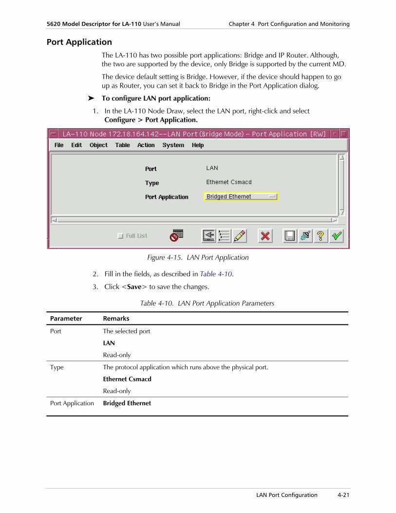
5620 Model Descriptor for LA-110 User’s Manual Chapter 4 Port Configuration and Monitoring
LAN Port Configuration 4-21
Port Application The LA-110 has two possible port applications: Bridge and IP Router. Although, the two are supported by the device, only Bridge is supported by the current MD.
The device default setting is Bridge. However, if the device should happen to go up as Router, you can set it back to Bridge in the Port Application dialog.
To configure LAN port application:
1. In the LA-110 Node Draw, select the LAN port, right-click and select Configure > Port Application.
Figure 4-15. LAN Port Application
2. Fill in the fields, as described in Table 4-10.
3. Click <Save> to save the changes.
Table 4-10. LAN Port Application Parameters
Parameter Remarks
Port The selected port
LAN
Read-only
Type The protocol application which runs above the physical port.
Ethernet Csmacd
Read-only
Port Application Bridged Ethernet

Chapter 4 Port Configuration and Monitoring 5620 Model Descriptor for LA-110 User’s Manual
4-22 LAN Port Configuration
Interface Information To view LAN port interface information:
• In the LA-110 Node Draw, select the LAN port, right-click and select Configure > Interface Info.
Figure 4-16. LAN Port Interface Information
Table 4-11. LAN Port Interface Information Parameters
Parameter Remarks
Port The selected port
LAN
Read-only
Type Ethernet Csmacd
Read-only
Oper. Status The actual link status.
Up, Down
Read-only

5620 Model Descriptor for LA-110 User’s Manual Chapter 4 Port Configuration and Monitoring
LAN Port Configuration 4-23
Table 4-11. LAN Port Interface Information Parameters (Cont.)
Parameter Remarks
MTU (byte) The size of the largest packet which can be sent/received on the interface, specified in octets. For interfaces that are used for transmitting network datagrams, this is the size of the largest network datagram that can be sent on the interface
Integer
Read-only
MAC Address The interface's MAC address at its protocol sub-layer.
MAC address format
Read-only
Last Change This field indicates the time of the last change on the port.
Read-only
Mode The port mode of operation.
Full Duplex, Half Duplex
Read-only
Rate (Mbps) The operation rate of the port.
10, 100 Mbps
Read-only
Status The port status.
Connected, Not Connected
Read-only
Bridge Configuration In the Navigator, you can view and modify LAN port Bridge parameters.
Basic tasks include viewing and configuring:
• Bridge parameters
• LAN table parameters
• VLAN table parameters
• VLAN for membership
• VLAN members
• Bridging table.
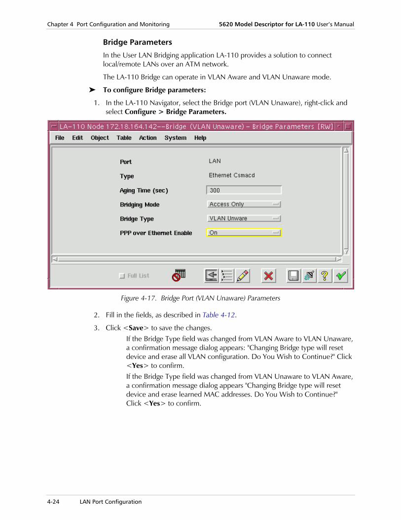
Chapter 4 Port Configuration and Monitoring 5620 Model Descriptor for LA-110 User’s Manual
4-24 LAN Port Configuration
Bridge Parameters
In the User LAN Bridging application LA-110 provides a solution to connect local/remote LANs over an ATM network.
The LA-110 Bridge can operate in VLAN Aware and VLAN Unaware mode.
To configure Bridge parameters:
1. In the LA-110 Navigator, select the Bridge port (VLAN Unaware), right-click and select Configure > Bridge Parameters.
Figure 4-17. Bridge Port (VLAN Unaware) Parameters
2. Fill in the fields, as described in Table 4-12.
3. Click <Save> to save the changes. If the Bridge Type field was changed from VLAN Aware to VLAN Unaware, a confirmation message dialog appears: "Changing Bridge type will reset device and erase all VLAN configuration. Do You Wish to Continue?" Click <Yes> to confirm. If the Bridge Type field was changed from VLAN Unaware to VLAN Aware, a confirmation message dialog appears "Changing Bridge type will reset device and erase learned MAC addresses. Do You Wish to Continue?" Click <Yes> to confirm.

5620 Model Descriptor for LA-110 User’s Manual Chapter 4 Port Configuration and Monitoring
LAN Port Configuration 4-25
Table 4-12. Bridge Port Parameters
Parameter Remarks
Port The selected port
LAN
Read-only
Type The protocol application which runs above the physical port.
Ethernet Csmacd
Read-only
Aging Time (sec) The timeout period in seconds for aging out stored information.
300...604,800
Bridging Mode Bridging mode can be between the Ethernet port and the ATM port (where there is no bridging between VCs), or between both ports, and also between VCs.
• Access Only: The traffic reaching the LAN port is forwarded through the WAN ports.
• Access and Switching: The Bridge forwards LAN traffic addressed to WAN destinations that can be reached only through the WAN ports, and in addition enables forwarding of traffic among the WAN ports.
Bridge Type The VLAN Mode. Upon Mode changing, all LAN VCCs will be deleted by the agent from all tables that include LAN VCCs
VLAN Unaware, VLAN Aware
PPP over Ethernet Enable
Enables or disables transparent PPP over Ethernet bridge. When PPP over Ethernet is enabled, non PPP traffic is blocked by the bridge.
On, Off
LAN Table
The LAN port can be configured to operate as a MAC Bridge. The MAC Bridge provides Layer 2 connectivity with transparent VLAN support for user-equipment. Each Bridge contains up to 16 ATM Bridge ports.
This menu option is available only for VLAN Aware bridge ports.
The LAN Table displays the learned MAC addresses and the added static entries.
Viewing LAN Table Parameters
To view LAN Table parameters:
• In the LA-110 Navigator, select the Bridge port (VLAN Aware), right-click and select Configure > LAN Table (or select Configure > LAN Table > All)
Note

Chapter 4 Port Configuration and Monitoring 5620 Model Descriptor for LA-110 User’s Manual
4-26 LAN Port Configuration
Figure 4-18. Bridge Port (VLAN Aware) LAN Table
Table 4-13. Bridge Port (VLAN Aware) LAN Table Parameters
Parameter Remarks
VLAN ID The Bridge port VLAN-ID.
1…4094
Read-only
Bridge Port Bridge Port selection is possible only for a new entry.
• ATM: ports 1…16
• Ethernet: port 9
Read-only
MAC Address The MAC Address format.
Read-only
Type Provides information about all entries, learned dynamically or statically configured by management, in each filtering database.
• Learned: Created by self-learning of the bridge
• Static: user-created
Read-only
Adding Static LAN Entries
You can add static MAC addresses to the bridging table of the LA-110 LAN port. You may define up to 32 static MAC addresses. If this number is exceeded, you must delete an existing MAC address before a new one can be added.
To add static LAN entries:
1. In the LA-110 Navigator, select the Bridge port (VLAN Aware), right-click and select Configure > LAN Table > Static.

5620 Model Descriptor for LA-110 User’s Manual Chapter 4 Port Configuration and Monitoring
LAN Port Configuration 4-27
Figure 4-19. Bridge Port (VLAN Aware) LAN Table – Static Parameters
2. Fill in the fields, as described in Table 4-13. If the number of static LAN entries added, exceeds the limit, the following message appears on the Status bar: "The number of Static LAN entries cannot exceed 32."Set won't be performed."
3. In the LAN Static Table dialog, select Table > Add Row.
4. In the Static Table, in the VLAN ID field, edit the VLAN ID.
5. In the Static Table, select the Bridge Port which will be a member in the VLAN.
6. In the MAC Address field, enter the MAC address.
7. Click <Save> to save the changes.
Removing All LAN Table Entries
To remove all LAN Table entries:
1. In the LA-110 Navigator, select the Bridge port (VLAN Aware), right-click and select Configure > LAN Table > Remove All Entries.
Figure 4-20. Bridge Port (VLAN Aware) LAN Table > Remove All Entries
2. In the Action field, select <Remove All Entries>. A confirmation message dialog appears: "Erasing LAN Table. Information will be lost."

Chapter 4 Port Configuration and Monitoring 5620 Model Descriptor for LA-110 User’s Manual
4-28 LAN Port Configuration
3. Click <Yes> to confirm. The entire LAN Table is erased.
VLAN Table
VLAN can be used to provide separation between traffic from different sources sharing the same physical transmission facilities, and to provide information on the relative priority the assigned to each frame. The characteristics and use of virtual LANs (VLANs) and of the MAC bridges capable of handling tagged frames are defined in IEEE Standard 802.1Q.
This menu option is available only for VLAN Aware bridge ports.
To configure VLAN Table parameters:
1. In the LA-110 Navigator, select the Bridge port (VLAN Aware), right-click and select Configure > VLAN Table.
Figure 4-21. Bridge Port (VLAN Aware) VLAN Table
2. Fill in the fields, as described in Table 4-14.
3. Click <Save> to save the changes. When Bridge mode is VLAN Aware, the procedure of VLAN creation is as follows:
1. In the VLAN Table dialog, select Table > Add Row.
2. In the VLAN Table, in the VLAN ID field, edit the VLAN ID.
3. In the VLAN Table, select the Bridge Port which will be a member in the VLAN
4. In the VLAN Name field, edit the VLAN Name. If the VLAN Name is not edited, the VLAN will be given a default name.
Note
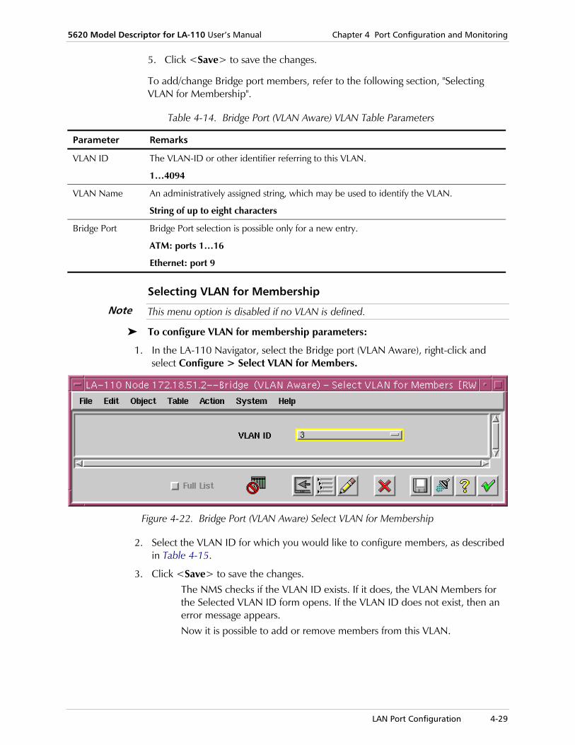
5620 Model Descriptor for LA-110 User’s Manual Chapter 4 Port Configuration and Monitoring
LAN Port Configuration 4-29
5. Click <Save> to save the changes.
To add/change Bridge port members, refer to the following section, "Selecting VLAN for Membership".
Table 4-14. Bridge Port (VLAN Aware) VLAN Table Parameters
Parameter Remarks
VLAN ID The VLAN-ID or other identifier referring to this VLAN.
1…4094
VLAN Name An administratively assigned string, which may be used to identify the VLAN.
String of up to eight characters
Bridge Port Bridge Port selection is possible only for a new entry.
ATM: ports 1…16
Ethernet: port 9
Selecting VLAN for Membership
This menu option is disabled if no VLAN is defined.
To configure VLAN for membership parameters:
1. In the LA-110 Navigator, select the Bridge port (VLAN Aware), right-click and select Configure > Select VLAN for Members.
Figure 4-22. Bridge Port (VLAN Aware) Select VLAN for Membership
2. Select the VLAN ID for which you would like to configure members, as described in Table 4-15.
3. Click <Save> to save the changes. The NMS checks if the VLAN ID exists. If it does, the VLAN Members for the Selected VLAN ID form opens. If the VLAN ID does not exist, then an error message appears. Now it is possible to add or remove members from this VLAN.
Note

Chapter 4 Port Configuration and Monitoring 5620 Model Descriptor for LA-110 User’s Manual
4-30 LAN Port Configuration
Table 4-15. Bridge Port (VLAN Aware) Select VLAN for Membership Parameters
Parameter Remarks
VLAN ID The VLAN-ID or other identifier referring to this VLAN.
1…4094 (of the existing VLANs)
The default is the last selected VLAN.
In order to open the VLAN Members window, the VLAN ID field has to be changed, otherwise the form will not be aware of any change and nothing will happen. Therefore, whenever the dialog is opened with the value of the desired VLAN ID, you can simply open the VLAN Members window directly.
VLAN Members
This menu option is disabled if no VLAN is defined.
In the VLAN Members window, you can add or remove members from a selected VLAN.
The VLAN ID that will be opened, will be the one that is configured in the Select VLAN for Members window
To configure VLAN members:
1. In the LA-110 Navigator, select the Bridge port (VLAN Aware), right-click and select Configure > VLAN Members.
Figure 4-23. Bridge Port (VLAN Aware) VLAN Members
Note
Note

5620 Model Descriptor for LA-110 User’s Manual Chapter 4 Port Configuration and Monitoring
LAN Port Configuration 4-31
2. Fill in the fields, as described in Table 4-16. The maximum number of VLANs members in all VLANs is 100. In LA-110, whenever you add a VLAN, you also assign a member in the same operation, where the maximum number of allowed VLANs is 100. However, if more then one member is assigned to a VLAN, the number of maximum VLANs decreases accordingly.
3. Click <Save> to save the changes.
Table 4-16. Bridge Port (VLAN Aware) VLAN Members Parameters
Parameter Remarks
VLAN ID The VLAN-ID or other identifier referring to this VLAN.
1…4094
Read-only
VLAN Name The VLAN user-defined or default name.
Read-only
Bridge Port The Bridge Ports that currently exist.
ATM: ports 1…16
Ethernet: port 9
Read-only
Tx Frame Type The transmitted frame type of the VLAN member.
Untagged, Tagged (default)
Read-only
Bridging Table
This menu option is enable only for VLAN Unaware bridges.
To view Bridging Table parameters:
1. In the LA-110 Navigator, select the Bridge port (VLAN Aware), right-click and select Configure > Bridging Table > View.
Figure 4-24. Bridge Port (VLAN Unaware) View Bridging Table
Note

Chapter 4 Port Configuration and Monitoring 5620 Model Descriptor for LA-110 User’s Manual
4-32 LAN Port Configuration
2. View the fields, as described in Table 4-17.
Table 4-17. Bridge Port (VLAN Unaware) View Bridging Table Parameters
Parameter Remarks
MAC Address A unicast MAC address for which the device has forwarding and/or filtering information.
Format: 00-00-00-00
Read-only
Type The type learned dynamically or statically, configured by management, in each Filtering Database.
Learned, Static
Read-only
Bridge Port The Bridge Ports that currently exist.
1…16 ATM, 9 Ethernet
Read-only
VPI The VPI value.
0..31
Read-only
VCI The VCI value.
0..255
Read-only
To edit Bridging Table parameters:
1. In the LA-110 Navigator, select the Bridge port (VLAN Aware), right-click and select Configure > Bridging Table > Edit.
The Bridging Table opens, displaying editable fields.
Figure 4-25. Bridge Port (VLAN Unaware) Edit Bridging Table
2. Fill in the fields, as described in Table 4-17.
3. Click <Save> to save the changes.

5620 Model Descriptor for LA-110 User’s Manual Chapter 4 Port Configuration and Monitoring
LAN Port Configuration 4-33
Bridge Port Configuration LA-110 supports up to 16 ATM Bridge Ports and one Ethernet Bridge Port.
The Ethernet Bridge Port is automatically created upon the setting of the LAN port to work in Bridge mode (as opposed to Router mode).
In the Navigator, you can add new Bridge ports.
Basic tasks include:
• Adding Bridge ports
• Deleting Bridge ports
• Configuring Bridge port parameters
LA-110 MD supports the following modes for bridge ports: VLAN aware and VLAN unaware.
Adding Bridge Ports
In the LA-110 Navigator, you can add new ATM Bridge ports for the LAN port, in Bridge – VLAN Aware mode.
A maximum of 17 Bridge ports can be added. One Ethernet Bridge port always exists and cannot be removed or added. 16 ATM Bridge Ports can be created or removed at any time.
To add a new bridge port:
1. In the LA-110 Navigator, select the LAN (Bridge) port (VLAN Aware), right-click and select Add Component > Bridge Port > Add Bridge Port.
The Add Bridge Port form opens.
Figure 4-26. Add Bridge Ports (VLAN Aware)
Note

Chapter 4 Port Configuration and Monitoring 5620 Model Descriptor for LA-110 User’s Manual
4-34 LAN Port Configuration
2. Fill in the fields, as described in Table 4-18.
3. Click <Save> to save the changes.
Table 4-18. Add Bridge Ports (VLAN Aware) Parameters
Parameter Remarks
Number The interface number.
1…16
The NMS will NOT display Bridge Ports that currently exist for this Bridge.
Physical Port The physical port.
ATM
The NMS will NOT display a value when all the possible Bridge Ports of this Type (Physical Port) currently exist.
The default value is the first selectable value (according to the mentioned order).
PVID The VLAN ID assigned to untagged frames or Priority-Tagged frames received on this port
1 (default)...4094
Ingress Filtering Determines whether incoming frames are discarded or accepted by the port.
Enable: enables ingress filtering and the device discards incoming frames for VLANs which do not include this Port in its Member set
Disable: disables ingress filtering, the port accepts all incoming frames.
Acceptable Frame Type
Determines whether untagged or Priority-tagged frame are received or discarded by the port.
All: untagged frames or Priority-tagged frames received on this port are accepted and assigned to the PVID for this port.
Only VLAN Tagged: the device discards untagged frames or Priority-tagged frames received on this port.
Deleting Bridge Ports
To delete a bridge port:
• In the LA-110 Navigator, select a Bridge port object (VLAN Aware), and on the Object menu, click <Delete>.
The selected Bridge object is deleted.
Configuring Bridge Port Parameters
To configure bridge port parameters:
1. In the LA-110 Navigator, select a Bridge port object (VLAN Unaware), right-click and select Configure > Parameters.

5620 Model Descriptor for LA-110 User’s Manual Chapter 4 Port Configuration and Monitoring
SHDSL Port Configuration 4-35
Figure 4-27. Ethernet Bridge Port Parameters
2. In the Physical Port field, select the physical port (ETH or ATM).
3. Click <Save> to save the changes.
4.7 SHDSL Port Configuration
LA-110 has one WAN (uplink) port, used to connect to the ATM network (this port is often referred to as an uplink port). Although the LA-110 uplink can come in several forms, in the current MD version, the WAN port will be always a 2-wire SHDSL interface in accordance with ITU-T Rec. G.991.2. The ATM network interface provides an ATM user-network interface (UNI) per ATM User-Network Interface (UNI) Specification (Version 3.1).
The interface supports the following ATM adaptation layers:
• AAL1: used for transparent transport of serial data streams, and for circuit emulation services (CES)
• AAL2: used to provide ATM Forum Loop Emulation Services (LES), which support PSTN and ISDN BRI and PRI access not supported
• AAL5: used for packet traffic (Frame Relay, Ethernet, IP).
The network port supports a wide range of ATM service categories (Classes of Service–CoS in ITU-T terminology): CBR, VBR, UBR and UBR+. LA-110 supports per-connection user-configurable traffic shaping and traffic contract enforcing, for improved QoS and efficient utilization of the ATM uplink bandwidth.
The layers of the SHDSL port include physical and ATM.
Basic tasks include:
• Configuring the SHDSL port physical layer
• Configuring the SHDSL port ATM layer.

Chapter 4 Port Configuration and Monitoring 5620 Model Descriptor for LA-110 User’s Manual
4-36 SHDSL Port Configuration
SHDSL Port - Physical Layer Basic tasks include viewing and configuring:
• Interface information
• Parameters
• Status.
Interface Information
To view SHDSL port physical layer interface information:
• In the LA-110 Node Draw, select the SHDSL port, right-click and select Configure > Physical Layer > Interface Info.
Figure 4-28. SHDSL Port – Physical Layer Interface Information
Table 4-19. SHDSL Port – Physical Layer Interface Information Parameters
Parameter Remarks
Port The selected port
SHDSL
Read-only
Type The protocol application which runs above the physical port.
SHDSL
Read-only
Oper. Status The actual link status.
Up, Down
Read-only
Last Change This field indicates the time of the last change on the port.
Read-only

5620 Model Descriptor for LA-110 User’s Manual Chapter 4 Port Configuration and Monitoring
SHDSL Port Configuration 4-37
Physical Parameters
To configure SHDSL port physical layer parameters:
1. In the LA-110 Node Draw, select the SHDSL port, right-click and select Configure > Physical Layer > Parameters.
Figure 4-29. SHDSL Port – Physical Layer Parameters
2. Fill in the fields, as described in Table 4-20.
3. Click <Save> to save the changes.
Changing the uplink physical layer parameters may cause a temporary disconnection of management for a few seconds, until the SHDSL port is synchronized with the new parameters.
Note

Chapter 4 Port Configuration and Monitoring 5620 Model Descriptor for LA-110 User’s Manual
4-38 SHDSL Port Configuration
Table 4-20. SHDSL Port – Physical Layer Parameters
Parameter Remarks
Port The selected port
SHDSL
Read-only
Type The protocol application which runs above the physical port.
SHDSL
Read-only
Wire Interface Displays the two-wire or optional four-wire operation for SHDSL Lines.
Two Wires, Four Wires
Read-only
Line Probe Enabled
Enables/disables support for Line Probe of the units in a SHDSL line. When Line Probe is enabled, the system performs Line Probing to find the best possible rate. If Line probe is disabled, the rate adaptation phase is skipped to shorten set up time.
Enabled, Disabled
Disabled when Wire Interface = Four wires
Power Backoff Configures the receiver at the associated segment endpoint to enable/disable power backoff mode.
Enabled, Disabled
When Wire Interface = Two Wires, and Line probe is enabled, at least one SNR margin must be enabled. (In this case, by default, Startup SNR Margin is enabled = 2.)
Enable Startup SNR Margins (dB)
Determines the relevance of the Startup SNR Margins (dB) field.
Enabled, Disabled
Startup SNR Margins (dB)
Specifies the downstream current condition target SNR margin for a SHDSL line. The SNR margin is the difference between the desired SNR and the actual SNR. Target SNR margin is the desired SNR margin for a unit.
0..10
Disabled when “Line Probe Enabled” is disabled
Enable Worst Case SNR Margins (dB)
Indicates whether a target SNR margin is enabled or disabled.
Enabled, Disabled
Worst Case SNR Margins (dB)
Specifies the downstream worst case target SNR margin for a SHDSL line. The SNR margin is the difference between the desired SNR and the actual SNR. Target SNR margin is the desired SNR margin for a unit
0..10
Disabled when “Line Probe Enabled” is disabled

5620 Model Descriptor for LA-110 User’s Manual Chapter 4 Port Configuration and Monitoring
SHDSL Port Configuration 4-39
Table 4-20. SHDSL Port – Physical Layer Parameters (Cont.)
Parameter Remarks
Tx EOC Enables/disables support for remote management of the units in a SHDSL line from the STU-R via the EOC.
Enabled, Disabled
Read-only
Power Feeding Enables/disables support for optional power feeding in a SHDSL line.
No Power (N/A)
Read-only
Transmission Mode
Specifies the regional setting for the SHDSL line.
Annex A, Annex B
Power Spectral Density (PSD) Mask
Configures use of symmetric/asymmetric PSD (Power Spectral Density) Mask for the associated SHDSL Line. Support for symmetric PSD is mandatory for all supported data rates. Support for asymmetric PSD is optional.
Symmetric, Asymmetric
Asymmetric PSD Rate
The asymmetric PSD rate.
Not Applicable, Asymmetric
The Asymmetric PSD Line Rates:
The PSD Mask (Globespan) Asymmetric R1 for Annex A: 776, 784; for Annex B: 2,312
The PSD Mask (Globespan) Asymmetric R2 for Annex A: 1544, 1,552; for Annex B: 2,056
Enabled only when PSD = Asymmetric
Min. Line Rate (Kbps)
Configures the minimum transmission rate for the associated SHDSL Line in bits-per-second (bps). If the minimum line rate equals the maximum line rate, the line rate is considered 'fixed'. If the minimum line rate is less than the maximum line rate, the line rate is considered 'rate-adaptive'.
Minimum Line Rates for Symmetric PSD:
For Two Wire: 200
For Four Wires: 400
Max. Line Rate (Kbps)
Configures the maximum transmission rate for the associated SHDSL Line in bits-per-second (bps). If the minimum line rate equals the maximum line rate (hdsl2ShdslSpanMaxLineRate), the line rate is considered 'fixed'. If the minimum line rate is less than the maximum line rate, the line rate is considered 'rate-adaptive'.
Maximum Line Rates for Symmetric PSD:
For Two Wire: 2,312
For Four Wires: 4,624
Max. Line Rate is greater than Min. Rate when Line Probe is enabled. Equal to Min. rate when Line Probe is disabled
Changing line rate values may cause disconnection of MNG connection.
Note

Chapter 4 Port Configuration and Monitoring 5620 Model Descriptor for LA-110 User’s Manual
4-40 SHDSL Port Configuration
Status
The Physical Layer Status dialog displays the current status of the SHDSL port.
To view SHDSL port physical layer status:
• In the LA-110 Node Draw, select the SHDSL port, right-click and select Configure > Physical Layer > Status.
Figure 4-30. SHDSL Port – Physical Layer Status

5620 Model Descriptor for LA-110 User’s Manual Chapter 4 Port Configuration and Monitoring
SHDSL Port Configuration 4-41
Table 4-21. SHDSL Port – Physical Layer Status Parameters
Parameter Remarks
Port The selected port
SHDSL
Read-only
Type The protocol application which runs above the physical port.
SHDSL
Read-only
Bit Rate An estimate of the interface's current bandwidth in bits per second.
Read-only
DSP Version The version of the SHDSL standard implemented as reported in an Inventory Response message.
Read-only
Vendor SW Version
Vendor software version as reported in an Inventory Response message.
Read-only
Loop Attenuation (dB)
The current loop attenuation for this endpoint as reported in a Network or Customer Side Performance Status message.
Read-only
SNR Margin (dB) The current SNR margin for this endpoint as reported in a Status Response/SNR message.
Read-only
No Defect The current state of the endpoint.
On, Off
Read-only
Power Back Off The current state of the endpoint.
On, Off
Read-only
SNR Margin Alarms
Displays the signal/noise margin in dB, measured at the instant the command has been received by LA-110.
On, Off
Read-only
Loop Attenuation Alarm
Displays the loop attenuation threshold in dB, measured at the instant the command has been received by LA-110.
On, Off
Read-only

Chapter 4 Port Configuration and Monitoring 5620 Model Descriptor for LA-110 User’s Manual
4-42 SHDSL Port Configuration
Table 4-21. SHDSL Port – Physical Layer Status Parameters (Cont.)
Parameter Remarks
LOSW Failure Alarm
Displays the number of seconds with loss of sync word events accumulated for each link.
On, Off
Read-only
Loopback Active The current state of the endpoint.
On, Off
Read-only
SHDSL Port - ATM Layer Basic tasks include viewing and configuring:
• Interface information
• Parameters
• VCL Table.
Interface Information
To view SHDSL port ATM layer interface information:
1. In the LA-110 Node Draw, select the SHDSL port, right-click and select Configure > ATM Layer > Interface Info.
Figure 4-31. SHDSL Port – ATM Layer Interface Information

5620 Model Descriptor for LA-110 User’s Manual Chapter 4 Port Configuration and Monitoring
SHDSL Port Configuration 4-43
Table 4-22. SHDSL Port – ATM Layer Interface Information Parameters
Parameter Remarks
Port The selected port
SHDSL
Read-only
Type The protocol application which runs above the physical port.
ATM
Read-only
Oper. Status The actual link status.
Up, Down
Read-only
MTU (byte) The size of the largest packet which can be sent/received on the interface, specified in octets. For interfaces that are used for transmitting network datagrams, this is the size of the largest network datagram that can be sent on the interface
Integer
Read-only
Max CPS SDU Size
The maximum AAL5 CPCS SDU (service data unit) size in octets that is supported on the transmit direction of this VCC.
Read-only
Relevant only when the local VCL end-point is also the VCC end-point, and AAL5 is in use.
Available only for AAL Type = AAL5
Last Change This field indicates the time of the last change on the port.
Read-only

Chapter 4 Port Configuration and Monitoring 5620 Model Descriptor for LA-110 User’s Manual
4-44 SHDSL Port Configuration
Parameters
To configure SHDSL port ATM layer parameters:
1. In the LA-110 Node Draw, select the SHDSL port, right-click and select Configure > ATM Layer > Parameters.
Figure 4-32. SHDSL Port –ATM Layer Parameters
2. Fill in the fields, as described in Table 4-23.
3. Click <Save> to save the changes.

5620 Model Descriptor for LA-110 User’s Manual Chapter 4 Port Configuration and Monitoring
SHDSL Port Configuration 4-45
Table 4-23. SHDSL Port – ATM Layer Parameters
Parameter Remarks
Port The selected port
SHDSL
Read-only
Type The protocol application which runs above the physical port.
ATM
Read-only
Max Supported VCCs
The maximum number of VCCs supported at this ATM interface.
18
Read-only
No. of Configured VCCs
The number of VCCs currently in use at this ATM interface.
Read-only
Max Active VPI Bits
The maximum number of active VPI bits configured for use at the ATM interface. At the ATM UNI, the maximum number of active VPI bits configured for use ranges from 0 to 8 only.
5
Read-only
Max Active VCI Bits
The maximum number of active VCI bits configured for use at this ATM interface.
8
Read-only
Free Bandwidth (cell/sec)
The free rate in cells/sec.
Output rate – Allocated BW
Read-only
Idle Cell CLP Determines the CLP bit value for transmission in empty time slots.
CLP0, CLP1
Scrambling Adds scrambling to the communications with the network.
Enable, Disable
Shaping Mode The shaping mode
SW
HW, NCITS=1
HW, NCITS=2
Jitter Buffer (msec)
The field is set in ms and sets the Jitter Buffer size. The Jitter Buffer adapts the size of the LA140 traffic to the CDV (cell delay variation) of the ATM network.
1…30

Chapter 4 Port Configuration and Monitoring 5620 Model Descriptor for LA-110 User’s Manual
4-46 SHDSL Port Configuration
Table 4-23. SHDSL Port – ATM Layer Parameters (Cont.)
Parameter Remarks
OAM
Mode OAM support mode, which determines the interface's location in a segment.
Segment, End-to-end
Failure Indication
The OAM failure indication.
Disabled, AIS and RDI
VCL Table
To configure SHDSL port ATM layer VCL table parameters:
1. In the LA-110 Node Draw, select the SHDSL port, right-click and select Configure > ATM Layer > VCL Table.
Figure 4-33. SHDSL Port – ATM Layer VCL Table
2. Fill in the fields, as described in Table 4-24.
3. Click <Save> to save the changes.

5620 Model Descriptor for LA-110 User’s Manual Chapter 4 Port Configuration and Monitoring
SHDSL Port Configuration 4-47
Table 4-24. SHDSL Port – ATM Layer VCL Table Parameters
Parameter Remarks
Port The selected port
SHDSL
Read-only
Type The protocol application which runs above the physical port.
ATM
Read-only
VCL Table
VPI 0..31
VCI 0..255
Last Change This field indicates the time of the last change on the port.
Read-only
Oper. Status The actual link status.
Up, Down
Read-only
Traffic Descriptor
The Traffic Descriptor.
1…200
Read-only
Continuity Check
The VCC admin status.
Off-two-way (down), On-two way (up), On-source, On-sink
Read-only
AAL Type The type of AAL used on this VCC.
AAL1, AAL5
Read-only
Relevant only when the local VCL end-point is also the VCC end-point, and AAL is in use.

Chapter 4 Port Configuration and Monitoring 5620 Model Descriptor for LA-110 User’s Manual
4-48 CES E1 Port Configuration
Table 4-24. SHDSL Port – ATM Layer VCL Table Parameters (Cont.)
Parameter Remarks
Encapsulation Relevant only when the local VCL end-point is also the VCC end-point, and AAL5 is in use.
The type of data encapsulation used over the AAL5 SSCS layer.
Read-only
Available only for AAL Type = AAL5
Loopback Test Status
Indicates whether a loopback test is running.
On: the loop is currently running.
Off: the loop is not running.
Read-only
4.8 CES E1 Port Configuration
You can perform CES E1 port operations, in the Node draw, (or in the Port draw) and right-click and select the relevant shortcut menu option.
Basic tasks include viewing and configuring:
• Parameters
• Interface information
• Bundles configuration
• Bundles table
• Loopback testing.

5620 Model Descriptor for LA-110 User’s Manual Chapter 4 Port Configuration and Monitoring
CES E1 Port Configuration 4-49
Parameters To configure CES E1 port parameters:
1. In the LA-110 Node Draw, select the CES E1 port, right-click and select Configure > Parameters.
Figure 4-34. CES E1 Port –Parameters
2. Fill in the fields, as described in Table 4-25.
3. Click <Save> to save the changes. If the Line Type is changed to “Unframed”, a confirmation message appears: “Changing line type to Unframed requires device reset. Operation will RESET the device. Do you wish to continue?” Click <Yes> to confirm. If the Line Type is changed from “Unframed”, a confirmation message appears: “Changing line type to Framed requires device reset. Operation will RESET the device. Do you wish to continue?” Click <Yes> to confirm.
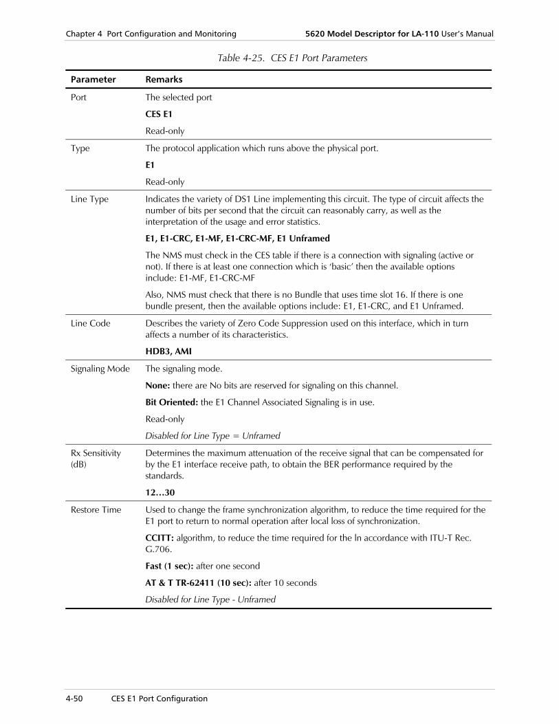
Chapter 4 Port Configuration and Monitoring 5620 Model Descriptor for LA-110 User’s Manual
4-50 CES E1 Port Configuration
Table 4-25. CES E1 Port Parameters
Parameter Remarks
Port The selected port
CES E1
Read-only
Type The protocol application which runs above the physical port.
E1
Read-only
Line Type Indicates the variety of DS1 Line implementing this circuit. The type of circuit affects the number of bits per second that the circuit can reasonably carry, as well as the interpretation of the usage and error statistics.
E1, E1-CRC, E1-MF, E1-CRC-MF, E1 Unframed
The NMS must check in the CES table if there is a connection with signaling (active or not). If there is at least one connection which is ‘basic’ then the available options include: E1-MF, E1-CRC-MF
Also, NMS must check that there is no Bundle that uses time slot 16. If there is one bundle present, then the available options include: E1, E1-CRC, and E1 Unframed.
Line Code Describes the variety of Zero Code Suppression used on this interface, which in turn affects a number of its characteristics.
HDB3, AMI
Signaling Mode The signaling mode.
None: there are No bits are reserved for signaling on this channel.
Bit Oriented: the E1 Channel Associated Signaling is in use.
Read-only
Disabled for Line Type = Unframed
Rx Sensitivity (dB)
Determines the maximum attenuation of the receive signal that can be compensated for by the E1 interface receive path, to obtain the BER performance required by the standards.
12…30
Restore Time Used to change the frame synchronization algorithm, to reduce the time required for the E1 port to return to normal operation after local loss of synchronization.
CCITT: algorithm, to reduce the time required for the ln accordance with ITU-T Rec. G.706.
Fast (1 sec): after one second
AT & T TR-62411 (10 sec): after 10 seconds
Disabled for Line Type - Unframed

5620 Model Descriptor for LA-110 User’s Manual Chapter 4 Port Configuration and Monitoring
CES E1 Port Configuration 4-51
Table 4-25. CES E1 Port Parameters (Cont.)
Parameter Remarks
Idle Code (hex) Selects the code transmitted to fill idle (unused) timeslots in the frames transmitted through this user port.
0x00..0xFF
Disabled for Line Type - Unframed
Signaling Sample Time (msec)
Determines how often the signaling of the DBCES connections are sampled and their activity.
100, 200, 500, 1000, 1500, 2000 msec
Disabled for Line Type - Unframed
Interface Information To view CES E1 port interface information:
• In the LA-110 Node Draw, select the CES E1 port, right-click and select Configure > Interface Info.
Figure 4-35. CES E1 Port – Interface Information

Chapter 4 Port Configuration and Monitoring 5620 Model Descriptor for LA-110 User’s Manual
4-52 CES E1 Port Configuration
Table 4-26. CES E1 Port – Interface Information Parameters
Parameter Remarks
Port The selected port
CES E1
Read-only
Type The protocol application which runs above the physical port.
E1
Read-only
Oper. Status The actual link status.
Up, Down
Read-only
Last Change This field indicates the time of the last change on the port.
Read-only
Bundles Configuration
Bundles Configuration is disabled when the Line Type is "Unframed".
Bundles configuration involves assigning an available time slot to a bundle.
To configure CES E1 port bundles configuration:
1. In the LA-110 Node Draw, select the CES E1 port, right-click and select Configure > Bundles Configuration.
Note

5620 Model Descriptor for LA-110 User’s Manual Chapter 4 Port Configuration and Monitoring
CES E1 Port Configuration 4-53
Figure 4-36. CES E1 Port – Bundles Configuration
2. Fill in the fields, as described in Table 4-27.
3. Click <Save> to save the changes.
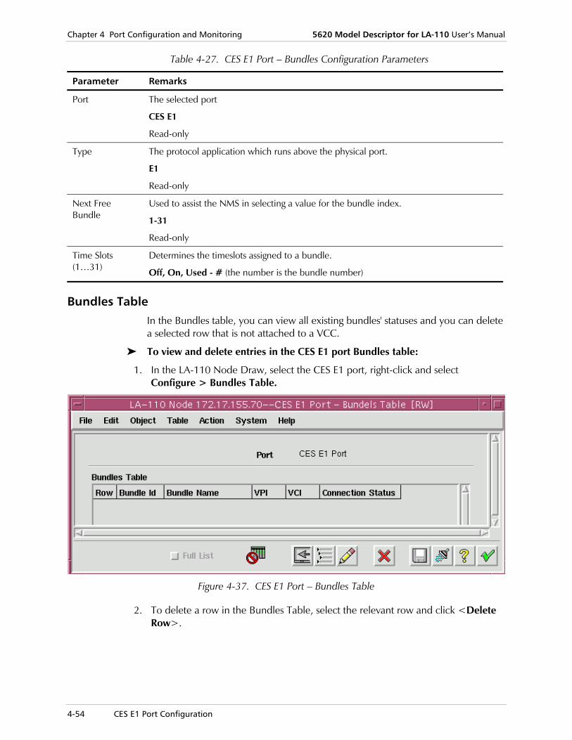
Chapter 4 Port Configuration and Monitoring 5620 Model Descriptor for LA-110 User’s Manual
4-54 CES E1 Port Configuration
Table 4-27. CES E1 Port – Bundles Configuration Parameters
Parameter Remarks
Port The selected port
CES E1
Read-only
Type The protocol application which runs above the physical port.
E1
Read-only
Next Free Bundle
Used to assist the NMS in selecting a value for the bundle index.
1-31
Read-only
Time Slots (1…31)
Determines the timeslots assigned to a bundle.
Off, On, Used - # (the number is the bundle number)
Bundles Table In the Bundles table, you can view all existing bundles' statuses and you can delete a selected row that is not attached to a VCC.
To view and delete entries in the CES E1 port Bundles table:
1. In the LA-110 Node Draw, select the CES E1 port, right-click and select Configure > Bundles Table.
Figure 4-37. CES E1 Port – Bundles Table
2. To delete a row in the Bundles Table, select the relevant row and click <Delete Row>.

5620 Model Descriptor for LA-110 User’s Manual Chapter 4 Port Configuration and Monitoring
CES E1 Port Configuration 4-55
Table 4-28. CES E1 Port – Bundles Table Parameters
Parameter Remarks
Port The selected port
CES E1
Read-only
Bundles Table
Bundle ID The bundle ID.
1…31
Bundle Name The bundle name, based on the index value the agent selected for the (new) Bundle interface.
Bundle 1…Bundle 31
VPI The VPI value which is associated with this bundle
VCI The VCI value which is associated with this bundle
Connection Status
The associated connection status.
Up, Down, Unknown
Loopback Testing To configure CES E1 port loopback testing:
• In the LA-110 Node Draw, select the CES E1 port, right-click and select Configure > Loopback Test.
Figure 4-38. CES E1 Port – Loopback Test
3. Fill in the fields, as described in Table 4-29.
4. Click <Save> to save the changes.
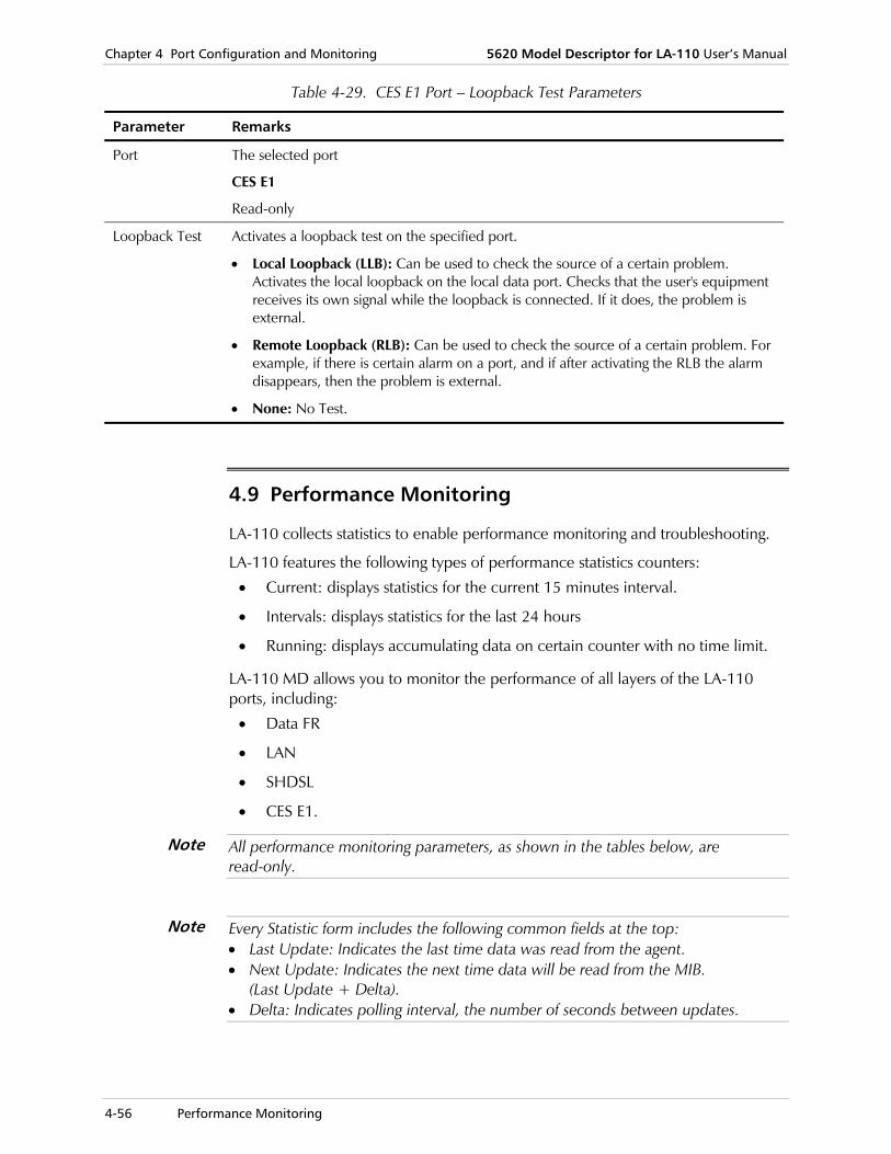
Chapter 4 Port Configuration and Monitoring 5620 Model Descriptor for LA-110 User’s Manual
4-56 Performance Monitoring
Table 4-29. CES E1 Port – Loopback Test Parameters
Parameter Remarks
Port The selected port
CES E1
Read-only
Loopback Test Activates a loopback test on the specified port.
• Local Loopback (LLB): Can be used to check the source of a certain problem. Activates the local loopback on the local data port. Checks that the user's equipment receives its own signal while the loopback is connected. If it does, the problem is external.
• Remote Loopback (RLB): Can be used to check the source of a certain problem. For example, if there is certain alarm on a port, and if after activating the RLB the alarm disappears, then the problem is external.
• None: No Test.
4.9 Performance Monitoring
LA-110 collects statistics to enable performance monitoring and troubleshooting.
LA-110 features the following types of performance statistics counters:
• Current: displays statistics for the current 15 minutes interval.
• Intervals: displays statistics for the last 24 hours
• Running: displays accumulating data on certain counter with no time limit.
LA-110 MD allows you to monitor the performance of all layers of the LA-110 ports, including:
• Data FR
• LAN
• SHDSL
• CES E1.
All performance monitoring parameters, as shown in the tables below, are read-only.
Every Statistic form includes the following common fields at the top: • Last Update: Indicates the last time data was read from the agent. • Next Update: Indicates the next time data will be read from the MIB.
(Last Update + Delta). • Delta: Indicates polling interval, the number of seconds between updates.
Note
Note
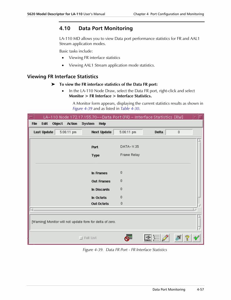
5620 Model Descriptor for LA-110 User’s Manual Chapter 4 Port Configuration and Monitoring
Data Port Monitoring 4-57
4.10 Data Port Monitoring
LA-110 MD allows you to view Data port performance statistics for FR and AAL1 Stream application modes.
Basic tasks include:
• Viewing FR interface statistics
• Viewing AAL1 Stream application mode statistics.
Viewing FR Interface Statistics To view the FR interface statistics of the Data FR port:
• In the LA-110 Node Draw, select the Data FR port, right-click and select Monitor > FR Interface > Interface Statistics.
A Monitor form appears, displaying the current statistics results as shown in Figure 4-39 and as listed in Table 4-30.
Figure 4-39. Data FR Port - FR Interface Statistics

Chapter 4 Port Configuration and Monitoring 5620 Model Descriptor for LA-110 User’s Manual
4-58 Data Port Monitoring
Table 4-30. Data FR Port Monitoring – FR Interface Statistics Parameters
Parameter Remarks
Port The selected port
Read-only
Type The interface type
Frame Relay
Read-only
In Frames The number of packets, delivered by this sub-layer to a higher (sub-)layer, addressed to a unicast address (i.e. not addressed to a multicast or broadcast address at this sub-layer.
Read-only
Out Frames The total number of packets that higher-level protocols requested be transmitted, and which were not addressed to a multicast or broadcast address at this sub-layer, including those that were discarded or not sent.
Read-only
In Discards The total number of frames discarded during processing by the receive path.
Read-only.
In Octets The total number of octets received on the interface, including framing characters.
Read-only
Out Octets The total number of octets transmitted out of the interface, including framing characters.
Read-only
Viewing AAL1 Stream Interface Statistics To view the AAL1 Stream interface statistics of the Data FR port:
• In the LA-110 Node Draw, select the Data FR port, right-click and select Monitor > AAL1 Stream Interface > Interface Statistics.
A Monitor form appears, displaying the current statistics results as shown in Figure 4-40 and as listed in Table 4-31.
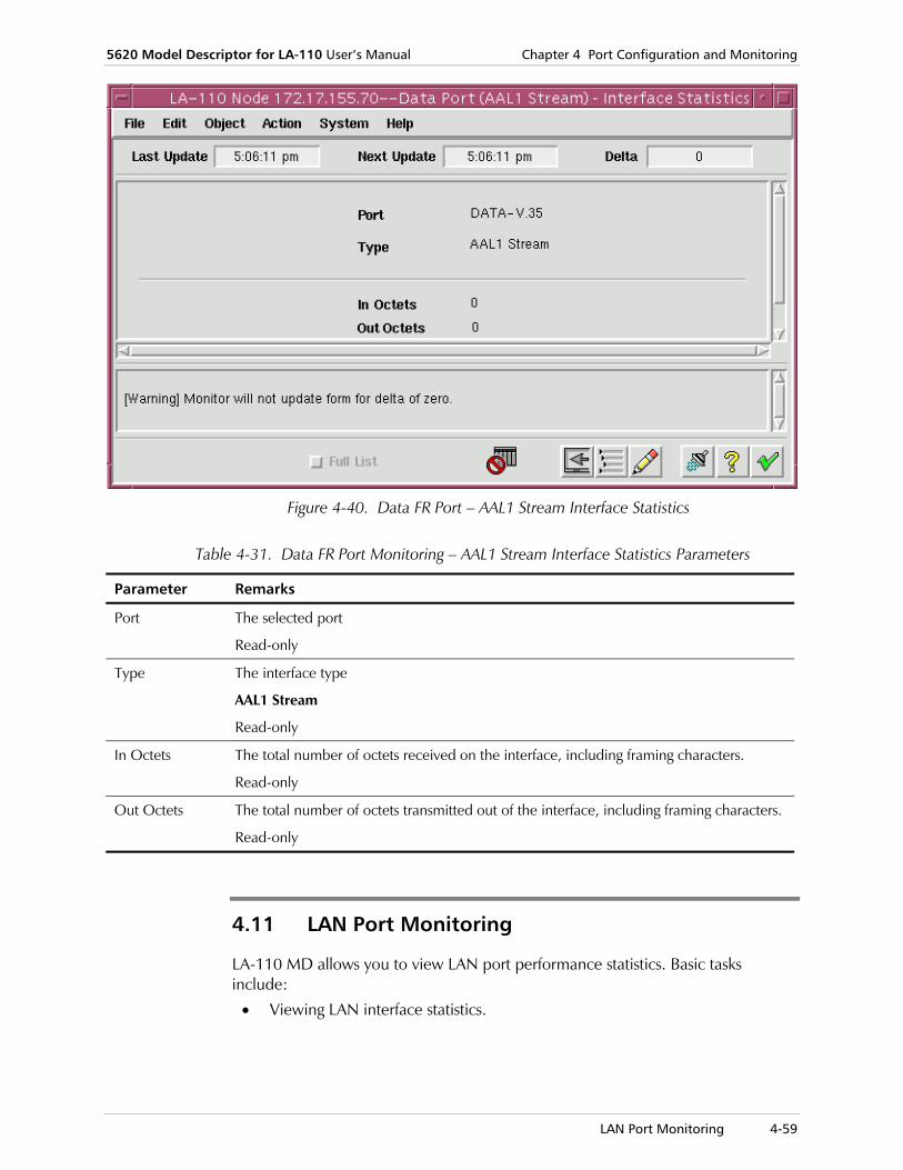
5620 Model Descriptor for LA-110 User’s Manual Chapter 4 Port Configuration and Monitoring
LAN Port Monitoring 4-59
Figure 4-40. Data FR Port – AAL1 Stream Interface Statistics
Table 4-31. Data FR Port Monitoring – AAL1 Stream Interface Statistics Parameters
Parameter Remarks
Port The selected port
Read-only
Type The interface type
AAL1 Stream
Read-only
In Octets The total number of octets received on the interface, including framing characters.
Read-only
Out Octets The total number of octets transmitted out of the interface, including framing characters.
Read-only
4.11 LAN Port Monitoring
LA-110 MD allows you to view LAN port performance statistics. Basic tasks include:
• Viewing LAN interface statistics.

Chapter 4 Port Configuration and Monitoring 5620 Model Descriptor for LA-110 User’s Manual
4-60 LAN Port Monitoring
Viewing LAN Interface Statistics To view interface statistics of the LAN port:
• In the LA-110 Node Draw, select the LAN port, right-click and select Monitor > LAN > Interface Statistics.
A Monitor form appears, displaying the current statistics results as shown in Figure 4-41 and as listed in Table 4-32.
Figure 4-41. LAN Port – Interface Statistics

5620 Model Descriptor for LA-110 User’s Manual Chapter 4 Port Configuration and Monitoring
LAN Port Monitoring 4-61
Table 4-32. LAN Port Interface Statistics Parameters
Parameter Remarks
Port The selected port
LAN
Read-only
Type The interface type
Ethernet Csmacd
Read-only
In Octets The total number of octets received on the interface, including framing characters.
Read-only
Applies to the LAN port only (and not the FE port)
In Frames The number of packets, delivered by this sub-layer to a higher (sub-)layer, addressed to a unicast address (i.e. not addressed to a multicast or broadcast address at this sub-layer.
Read-only
Out Frames The total number of packets that higher-level protocols requested be transmitted, and which were not addressed to a multicast or broadcast address at this sub-layer, including those that were discarded or not sent.
Read-only
In Discards The total number of frames discarded during processing by the receive path.
Read-only
Out Discards The total number of frames discarded during processing by the transmit path.
Read-only
Received From Ethernet
Alignment Error Frames
Number of frames received with alignment errors
FCS Error Frames
Number of frames received with CRC errors (FCS – Frame Check Sequence)
Frames Too Long
The number of frames discarded by this port due to excessive size
Transmitted To Ethernet
Single Collision Frames
A counter of successfully transmitted frames for which transmission is inhibited by exactly one collision. Valid only in half duplex mode
Multiple Collision Frames
A counter of successfully transmitted frames for which transmission is inhibited by more than one collision. Valid only in half duplex mode

Chapter 4 Port Configuration and Monitoring 5620 Model Descriptor for LA-110 User’s Manual
4-62 SHDSL Port Monitoring
Table 4-32. LAN Port Interface Statistics Parameters (Cont.)
Parameter Remarks
Deferred Transmissions Frames
A counter of frames for which the first transmission attempt is delayed because the medium is busy. Valid only in half duplex mode
Late Collision Frames
The number of times that a collision is detected on a particular interface later then 512 bit-times into the transmission of a packet. Valid only in half duplex mode
Carrier Sense Error Frames
The number of times that the carrier sense condition was lost or never asserted when attempting to transmit a frame
Excessive Collisions
The numbers of times that a collision is detected on a particular interface above the set rate.
4.12 SHDSL Port Monitoring
LA-110 MD allows you to view SHDSL port performance statistics.
Basic tasks include:
• Viewing SHDSL physical layer statistics
• Viewing SHDSL ATM layer statistics
• Viewing SHDSL AAL1 statistics
• Viewing SHDSL AAL5 statistics.
Viewing SHDSL Physical Layer Statistics Basic tasks include:
• Viewing SHDSL current data statistics (interval and one day)
• Viewing SHDSL intervals data statistics
• Viewing SHDSL accumulated data statistics.
Current Data Statistics
Basic tasks include:
• Viewing SHDSL current interval data statistics
• Viewing SHDSL current day data statistics.
To view current data interval statistics of the SHDSL port:
• In the LA-110 Node Draw, select the SHDSL port, right-click and select Monitor > Physical Layer > Current Data > Interval.
A Monitor form appears, displaying the current interval data statistics results as shown in Figure 4-42 and as listed in Table 4-33.

5620 Model Descriptor for LA-110 User’s Manual Chapter 4 Port Configuration and Monitoring
SHDSL Port Monitoring 4-63
Figure 4-42. SHDSL Port – Physical Layer – Current Interval Data Statistics
Table 4-33. SHDSL Port – Physical Layer – Current Interval Data Statistics Parameters
Parameter Remarks
Port The selected port
SHDSL
Read-only
Type The interface type
SHDSL
Read-only
Time Elapsed The data of this group is for the current interval of 15 minutes. The Time Elapsed field shows how much time passed since the beginning of the current interval.
Read-only
Errored Seconds The number of Errored Seconds.
Read-only
Severely Errored Seconds (SESs)
The number of Severely Errored Seconds.
Read-only
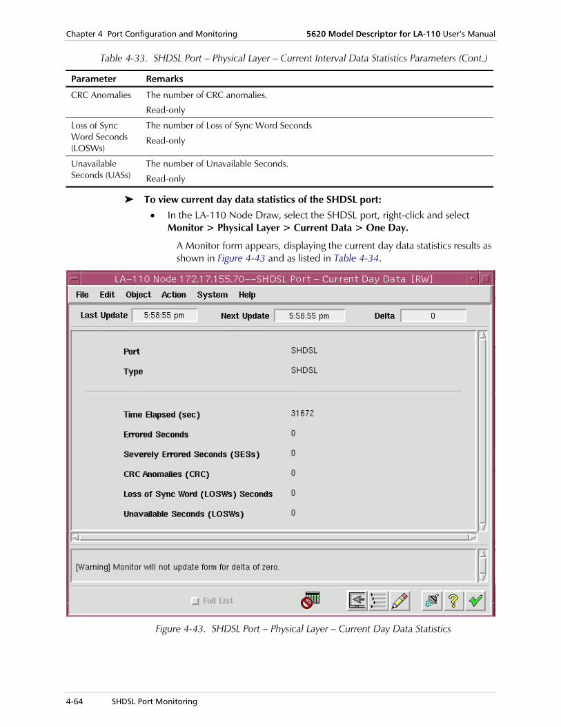
Chapter 4 Port Configuration and Monitoring 5620 Model Descriptor for LA-110 User’s Manual
4-64 SHDSL Port Monitoring
Table 4-33. SHDSL Port – Physical Layer – Current Interval Data Statistics Parameters (Cont.)
Parameter Remarks
CRC Anomalies The number of CRC anomalies.
Read-only
Loss of Sync Word Seconds (LOSWs)
The number of Loss of Sync Word Seconds
Read-only
Unavailable Seconds (UASs)
The number of Unavailable Seconds.
Read-only
To view current day data statistics of the SHDSL port:
• In the LA-110 Node Draw, select the SHDSL port, right-click and select Monitor > Physical Layer > Current Data > One Day.
A Monitor form appears, displaying the current day data statistics results as shown in Figure 4-43 and as listed in Table 4-34.
Figure 4-43. SHDSL Port – Physical Layer – Current Day Data Statistics

5620 Model Descriptor for LA-110 User’s Manual Chapter 4 Port Configuration and Monitoring
SHDSL Port Monitoring 4-65
Table 4-34. SHDSL Port – Physical Layer – Current Day Data Statistics Parameters
Parameter Remarks
Port The selected port
SHDSL
Read-only
Type The interface type
SHDSL
Read-only
Time Elapsed The data of this group is for the current 24 hours period (one day). The Time Elapsed field shows how much time passed since the beginning of the current interval (day).
Read-only
Errored Seconds The number of Errored Seconds.
Read-only
Severely Errored Seconds (SESs)
The number of Severely Errored Seconds.
Read-only
CRC Anomalies The number of CRC anomalies.
Read-only
Loss of Sync Word Seconds (LOSWs)
The number of Loss of Sync Word Seconds
Read-only
Unavailable Seconds (UASs)
The number of Unavailable Seconds.
Read-only
Intervals Data Statistics
To view intervals data statistics of the SHDSL port:
• In the LA-110 Node Draw, select the SHDSL port, right-click and select Monitor > Physical Layer > Intervals Data.
A Monitor form appears, displaying the intervals data statistics results as shown in Figure 4-44 and as listed in Table 4-35.

Chapter 4 Port Configuration and Monitoring 5620 Model Descriptor for LA-110 User’s Manual
4-66 SHDSL Port Monitoring
Figure 4-44. SHDSL Port – Physical Layer – Intervals Data Statistics
Table 4-35. SHDSL Port – Physical Layer – Intervals Data Statistics Parameters
Parameter Remarks
Port The selected port
SHDSL
Read-only
Type The interface type
SHDSL
Read-only
Interval Table
Int. No. The number of intervals.
Read-only
From (hh:mm) The start time of the interval in hours and minutes.
Read-only

5620 Model Descriptor for LA-110 User’s Manual Chapter 4 Port Configuration and Monitoring
SHDSL Port Monitoring 4-67
Table 4-35. SHDSL Port – Physical Layer – Intervals Data Statistics Parameters (Cont.)
Parameter Remarks
To (hh:mm) The end time of the interval in hours and minutes.
Read-only
Errored Seconds The number of Errored Seconds.
Read-only
Severely Errored Seconds (SESs)
The number of Severely Errored Seconds.
Read-only
CRC Anomalies The number of CRC anomalies.
Read-only
Loss of Sync Word Seconds (LOSWs)
The number of Loss of Sync Word Seconds
Read-only
Unavailable Seconds (UASs)
The number of Unavailable Seconds.
Read-only
Accumulated Data Statistics
The Accumulated Data Statistics dialog shows running counters, as described previously.
To view accumulated data statistics of the SHDSL port:
• In the LA-110 Node Draw, select the SHDSL port, right-click and select Monitor > Physical Layer > Accumulated Data.
A Monitor form appears, displaying the accumulated data statistics results as shown in Figure 4-45 and as listed in Table 4-33.

Chapter 4 Port Configuration and Monitoring 5620 Model Descriptor for LA-110 User’s Manual
4-68 SHDSL Port Monitoring
Figure 4-45. SHDSL Port – Physical Layer – Accumulated Data Statistics
Viewing SHDSL ATM Layer Statistics Basic tasks include:
• Viewing TC sublayer faults
• Viewing interface statistics
• Viewing VCL statistics.
TC Sublayers Faults
To view TC sublayer faults statistics of the SHDSL port:
• In the LA-110 Node Draw, select the SHDSL port, right-click and select Monitor > ATM Layer > TC Sublayer Faults.
A Monitor form appears, displaying the TC sublayer faults statistics results as shown in Figure 4-46 and as listed in Table 4-36.

5620 Model Descriptor for LA-110 User’s Manual Chapter 4 Port Configuration and Monitoring
SHDSL Port Monitoring 4-69
Figure 4-46. SHDSL Port – ATM Layer – TC Sublayer Faults Statistics
Table 4-36. SHDSL Port – ATM Layer – TC Sublayer Faults Statistics Parameters
Parameter Remarks
Port The selected port
SHDSL
Read-only
Type The interface type
ATM
Read-only
OCD Events The number of times the Out of Cell Delineation (OCD) events occur. If seven consecutive ATM cells have Header Error Control (HEC) violations, an OCD event occurs. A high number of OCD events may indicate a problem with the TC Sublayer.
Read-only
TC Alarm State This variable indicates if there is an alarm present for the TC Sublayer. The value lcdFailure indicates that a Loss of Cell Delineation (LCD) failure state has been declared for the TC Sublayer. Transition from failure to the no alarm state occurs when six consecutive ATM cells are received with valid HEC, followed by about 10 seconds of acceptable working signal.
No Alarm LCD Failure
Read-only

Chapter 4 Port Configuration and Monitoring 5620 Model Descriptor for LA-110 User’s Manual
4-70 SHDSL Port Monitoring
Interface Statistics
To view interface statistics of the SHDSL port:
• In the LA-110 Node Draw, select the SHDSL port, right-click and select Monitor > ATM Layer > Interface Statistics.
A Monitor form appears, displaying the interface statistics results as shown in Figure 4-47 and as listed in Table 4-37.
Figure 4-47. SHDSL Port – ATM Layer – Interface Statistics

5620 Model Descriptor for LA-110 User’s Manual Chapter 4 Port Configuration and Monitoring
SHDSL Port Monitoring 4-71
Table 4-37. SHDSL Port – ATM Layer – Interface Statistics Parameters
Parameter Remarks
Port The selected port
SHDSL
Read-only
Type The interface type
ATM
Read-only
Traffic
In Cells The total number of octets received on the interface, including framing characters.
Read-only
Out Cells The total number of octets transmitted out of the interface, including framing characters.
Read-only
In CLP0s The number of cells received with correct HECs and CLP=0 and not misrouted.
Read-only
Out CLP0s The number of cells transmitted with CLP=0.
Read-only
In CLP1s The number of cells received with correct HECs and CLP=1 and not misrouted.
Read-only
Out CLP1s The number of cells transmitted with CLP=1.
Read-only
In EFCIs The number of cells received with EFCI bit set by the Agent.
Read-only
In OAM The number of OAM cells received with correct HECs.
Read-only
Out OAM The number of transmitted OAM cells.
Read-only
Errors
In Discards The total number of frames discarded during processing by the receive path.
Read-only
In Errors The number of inbound packets which were chosen to be discarded even though no errors had been detected to prevent their being deliverable to a higher-layer protocol. One possible reason for discarding such a packet could be to free up buffer space.
Read-only
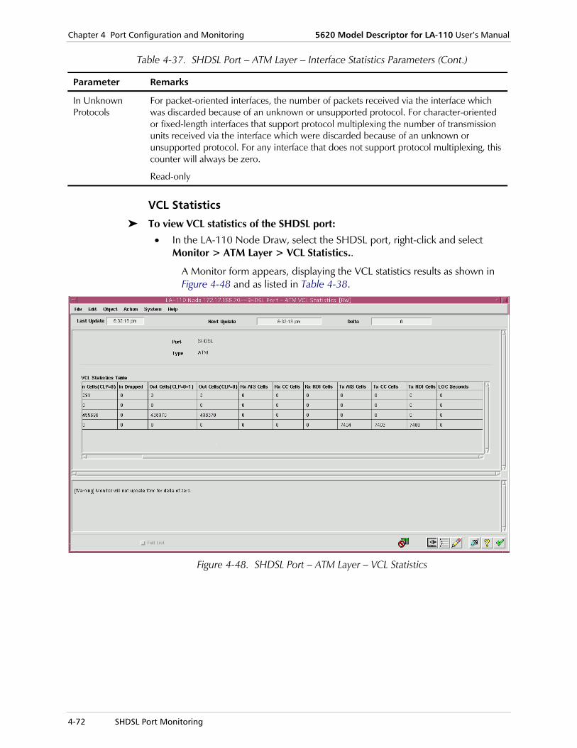
Chapter 4 Port Configuration and Monitoring 5620 Model Descriptor for LA-110 User’s Manual
4-72 SHDSL Port Monitoring
Table 4-37. SHDSL Port – ATM Layer – Interface Statistics Parameters (Cont.)
Parameter Remarks
In Unknown Protocols
For packet-oriented interfaces, the number of packets received via the interface which was discarded because of an unknown or unsupported protocol. For character-oriented or fixed-length interfaces that support protocol multiplexing the number of transmission units received via the interface which were discarded because of an unknown or unsupported protocol. For any interface that does not support protocol multiplexing, this counter will always be zero.
Read-only
VCL Statistics
To view VCL statistics of the SHDSL port:
• In the LA-110 Node Draw, select the SHDSL port, right-click and select Monitor > ATM Layer > VCL Statistics..
A Monitor form appears, displaying the VCL statistics results as shown in Figure 4-48 and as listed in Table 4-38.
Figure 4-48. SHDSL Port – ATM Layer – VCL Statistics

5620 Model Descriptor for LA-110 User’s Manual Chapter 4 Port Configuration and Monitoring
SHDSL Port Monitoring 4-73
Table 4-38. SHDSL Port – ATM Layer – VCL Statistics Parameters
Parameter Remarks
Port The selected port
SHDSL
Read-only
Type The interface type
ATM
Read-only
VPI The VPI value of the VCL.
Read-only
VCI The VCI value of the VCL
Read-only
In Cells (CLP=0+1)
The total number of cells received with correct HECs.
Read-only
In Cells (CLP=0) The number of cells received with correct HECs and CLP=0.
Read-only
In Dropped The number of cells, in ingress direction, discarded due to policing violation
Read-only
Out Cells (CLP=0+1)
The total number of cells transmitted.
Read-only
Out Cells (CLP=0)
The number of cells transmitted with CLP=0.
Read-only
Rx AIS Cells Total number of AIS cells received on the VC.
Read-only
Rx CC Cells Total number of Continuity Check cells that were received on the VC.
Read-only
Rx RDI Cells Total number of RDI cells received on a VC.
Read-only
Tx AIS Cells Total number of AIS cells that were transmitted on a VC.
Read-only
Tx CC Cells Total number of continuity check cells transmitted on a VC (when there is no data cells and the connection is in 'source' continuity check mode).
Read-only

Chapter 4 Port Configuration and Monitoring 5620 Model Descriptor for LA-110 User’s Manual
4-74 SHDSL Port Monitoring
Table 4-38. SHDSL Port – ATM Layer – VCL Statistics Parameters (Cont.)
Parameter Remarks
Tx RDI Cells Total number of RDI cells transmitted on a VC.
Read-only
LOC Seconds Total number of seconds during which there was loss of continuity on the VC - no data and no continuity check cells were received on the VC whilst it was in 'sink' continuity check mode.
Read-only
Viewing SHDSL AAL1 statistics Basic tasks include:
• Viewing interface statistics
• Viewing VCC statistics.
Interface Statistics
To view AAL1 interface statistics of the SHDSL port:
• In the LA-110 Node Draw, select the SHDSL port, right-click and select Monitor > AAL1 > Interface Statistics.
A Monitor form appears, displaying the AAL1 interface statistics results as shown in Figure 4-49 and as listed in Table 4-39.

5620 Model Descriptor for LA-110 User’s Manual Chapter 4 Port Configuration and Monitoring
SHDSL Port Monitoring 4-75
Figure 4-49. SHDSL Port – AAL1 – Interface Statistics
Table 4-39. SHDSL Port – AAL1 – Interface Statistics Parameters
Parameter Remarks
Port The selected port
SHDSL
Read-only
Type The interface type
AAL1
Read-only
In Cells The total number of octets received on the interface, including framing characters.
Read-only
Out Cells The total number of octets transmitted out of the interface, including framing characters.
Read-only
SNP Errors (CES/DBCES)
The total number of SNP errors (including CES/DBCES).
Read-only
Sequence Errors (CES/DBCES)
The total number of sequence errors (including CES/DBCES).
Read-only

Chapter 4 Port Configuration and Monitoring 5620 Model Descriptor for LA-110 User’s Manual
4-76 SHDSL Port Monitoring
Table 4-39. SHDSL Port – AAL1 – Interface Statistics Parameters (Cont.)
Parameter Remarks
If there are no transparent AAL1 cross-connections, the following fields are disabled.
SNP Errors (Not CES/DBCES)
The total number of SNP errors (not including CES/DBCES).
Read-only
Sequence Errors (Not CES/DBCES)
The total number of sequence errors (not including CES/DBCES).
Read-only
VCC Statistics
To view AAL1 VCC statistics of the SHDSL port:
• In the LA-110 Node Draw, select the SHDSL port, right-click and select Monitor > AAL1 > VCC Statistics.
A Monitor form appears, displaying the AAL1 VCC statistics results, including two tables, one for CES/DBCES and one for transparent connections , as shown in Figure 4-50 and as listed in Table 4-40.
Figure 4-50. SHDSL Port – AAL1 – VCC Statistics

5620 Model Descriptor for LA-110 User’s Manual Chapter 4 Port Configuration and Monitoring
SHDSL Port Monitoring 4-77
Table 4-40. SHDSL Port – AAL1 – VCC Statistics Parameters
Parameter Remarks
Port The selected port
SHDSL
Read-only
Type The interface type
AAL1
Read-only
AAL1 VCC Table – CES XC / Transparent XC
VPI The VPI value of the AAL1 VCC.
Read-only
VCI The VCI value of the AAL1 VCC.
Read-only
Rx Seq Errors Total number of sequence numbering errors detected in the cells received for the corresponding connection.
Read-only
Rx SNP Errors Total number of SNP errors detected in the cells received for the corresponding connection.
Read-only
Rx Resync Total number of resynchronization errors that occurred for the corresponding connection.
Read-only
Not applicable for AAL1 transparent XCs
Pointer Parity Errors
Total number of pointer errors detected in the cells received for the corresponding connection.
Read-only
Not applicable for AAL1 transparent XCs
Viewing SHDSL AAL5 statistics Basic tasks include:
• Viewing interface statistics
• Viewing VCC statistics.
Interface Statistics
To view AAL5 interface statistics of the SHDSL port:
• In the LA-110 Node Draw, select the SHDSL port, right-click and select Monitor > AAL5 > Interface Statistics.
A Monitor form appears, displaying the AAL5 interface statistics results as shown in Figure 4-51 and as listed in Table 4-41.

Chapter 4 Port Configuration and Monitoring 5620 Model Descriptor for LA-110 User’s Manual
4-78 SHDSL Port Monitoring
Figure 4-51. SHDSL Port – AAL5 – Interface Statistics

5620 Model Descriptor for LA-110 User’s Manual Chapter 4 Port Configuration and Monitoring
SHDSL Port Monitoring 4-79
Table 4-41. SHDSL Port – AAL5 – Interface Statistics Parameters
Parameter Remarks
Port The selected port
SHDSL
Read-only
Type The interface type
AAL5
Read-only
In Frames The number of packets, delivered by this sub-layer to a higher (sub-)layer, which were not addressed to a multicast or broadcast address at this sub-layer.
Read-only
Out Frames The total number of packets that higher-level protocols requested be transmitted, and which were not addressed to a multicast or broadcast address at this sub-layer, including those that were discarded or not sent.
Read-only
In Discards The total number of frames discarded during processing by the receive path.
Read-only
Out Discards The total number of frames discarded during processing by the transmit path.
Read-only
In Errors For packet-oriented interfaces, the number of inbound packets that contained errors preventing them from being deliverable to a higher-layer protocol. For character- oriented or fixed-length interfaces, the number of inbound transmission units that contained errors preventing them from being deliverable to a higher-layer protocol.
Read-only
Out Errors For packet-oriented interfaces, the number of outbound packets that could not be transmitted because of errors. For character-oriented or fixed-length interfaces, the number of outbound transmission units that could not be transmitted because of errors.
Read-only
In Octets The total number of octets received on the interface, including framing characters.
Read-only
Out Octets The total number of octets transmitted out of the interface, including framing characters.
Read-only

Chapter 4 Port Configuration and Monitoring 5620 Model Descriptor for LA-110 User’s Manual
4-80 SHDSL Port Monitoring
VCC Statistics
To view AAL5 VCC statistics of the SHDSL port:
• In the LA-110 Node Draw, select the SHDSL port, right-click and select Monitor > AAL5 > VCC Statistics.
A Monitor form appears, displaying the AAL5 VCC statistics results as shown in Figure 4-52 and as listed in Table 4-42.
Figure 4-52. SHDSL Port – AAL5 – VCC Statistics

5620 Model Descriptor for LA-110 User’s Manual Chapter 4 Port Configuration and Monitoring
CES E1 Port Monitoring 4-81
Table 4-42. SHDSL Port – AAL5 – VCC Statistics Parameters
Parameter Remarks
Port The selected port
SHDSL
Read-only
Type The interface type
AAL5
Read-only
AAL5 VCC Table
VPI The VPI value of the AAL5 VCC.
Read-only
VCI The VCI value of the AAL5 VCC.
Read-only
CRC Error The number of AAL5 CPCS PDUs received with CRC-32 errors on this AAL5 VCC at the interface associated with an AAL5 entity.
Read-only
SAR Timeouts The number of partially re-assembled AAL5 CPCS PDUs which were discarded on this AAL5 VCC at the interface associated with an AAL5 entity because they were not fully re-assembled within the required time period. If the re-assembly timer is not supported, then this object contains a zero value.
Read-only
Oversized SDUs The number of AAL5 CPCS PDUs discarded on this AAL5 VCC at the interface associated with an AAL5 entity because the AAL5 SDUs were too large.
Read-only
4.13 CES E1 Port Monitoring
LA-110 MD allows you to view CES E1 port performance statistics.
Basic tasks include:
• Viewing current data
• Viewing interval data.
Current Data Statistics To view current day data statistics of the CES E1 port:
• In the LA-110 Node Draw, select the CES E1 port, right-click and select Monitor > Current Data.
A Monitor form appears, displaying the CES E1 port current data statistics results as shown in Figure 4-53 and as listed in Table 4-43.

Chapter 4 Port Configuration and Monitoring 5620 Model Descriptor for LA-110 User’s Manual
4-82 CES E1 Port Monitoring
Figure 4-53. CES E1 Port – Current Data Statistics
Table 4-43. CES E1 Port – Current Data Statistics Parameters
Parameter Remarks
Port The selected port
CES E1
Read-only
Type The interface type
E1
Read-only

5620 Model Descriptor for LA-110 User’s Manual Chapter 4 Port Configuration and Monitoring
CES E1 Port Monitoring 4-83
Table 4-43. CES E1 Port – Current Data Statistics Parameters (Cont.)
Parameter Remarks
Time Elapsed The time passed since the beginning of the current 15 minute interval.
Read-only
Errored Seconds The number of Errored Seconds.
Read-only
Severely Errored Seconds (SESs)
The number of Severely Errored Seconds.
Read-only
Unavailable Seconds (UASs)
The number of Unavailable Seconds.
Read-only
Controlled Slip Seconds
The number of Controlled Slip Seconds.
Read-only
Bursty Errored Seconds
The number of Bursty Errored Seconds.
Read-only
Loss of Frame Count
The number of Loss of Frame events measured that were encountered in the current 15-minute interval.
Read-only
Intervals Data Statistics To view intervals data statistics of the CES E1 port:
• In the LA-110 Node Draw, select the CES E1 port, right-click and select Monitor > Intervals Data.
A Monitor form appears, displaying the CES E1 port intervals data statistics results as shown in Figure 4-44 and as listed in Table 4-35.

Chapter 4 Port Configuration and Monitoring 5620 Model Descriptor for LA-110 User’s Manual
4-84 CES E1 Port Monitoring
Figure 4-54. CES E1 Port – Intervals Data Statistics
Table 4-44. CES E1 Port – Intervals Data Statistics Parameters
Parameter Remarks
Port The selected port
CES E1
Read-only
Type The interface type
CES E1
Read-only
No. of Intervals The number of intervals.
Read-only
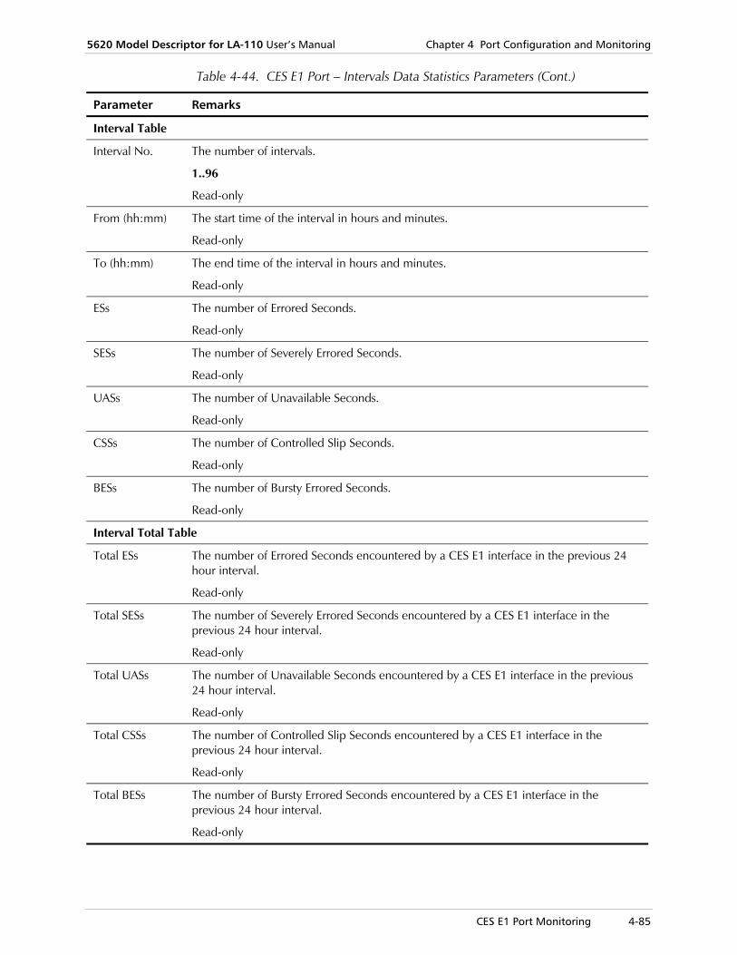
5620 Model Descriptor for LA-110 User’s Manual Chapter 4 Port Configuration and Monitoring
CES E1 Port Monitoring 4-85
Table 4-44. CES E1 Port – Intervals Data Statistics Parameters (Cont.)
Parameter Remarks
Interval Table
Interval No. The number of intervals.
1..96
Read-only
From (hh:mm) The start time of the interval in hours and minutes.
Read-only
To (hh:mm) The end time of the interval in hours and minutes.
Read-only
ESs The number of Errored Seconds.
Read-only
SESs The number of Severely Errored Seconds.
Read-only
UASs The number of Unavailable Seconds.
Read-only
CSSs The number of Controlled Slip Seconds.
Read-only
BESs The number of Bursty Errored Seconds.
Read-only
Interval Total Table
Total ESs The number of Errored Seconds encountered by a CES E1 interface in the previous 24 hour interval.
Read-only
Total SESs The number of Severely Errored Seconds encountered by a CES E1 interface in the previous 24 hour interval.
Read-only
Total UASs The number of Unavailable Seconds encountered by a CES E1 interface in the previous 24 hour interval.
Read-only
Total CSSs The number of Controlled Slip Seconds encountered by a CES E1 interface in the previous 24 hour interval.
Read-only
Total BESs The number of Bursty Errored Seconds encountered by a CES E1 interface in the previous 24 hour interval.
Read-only

Chapter 4 Port Configuration and Monitoring 5620 Model Descriptor for LA-110 User’s Manual
4-86 CES E1 Port Monitoring
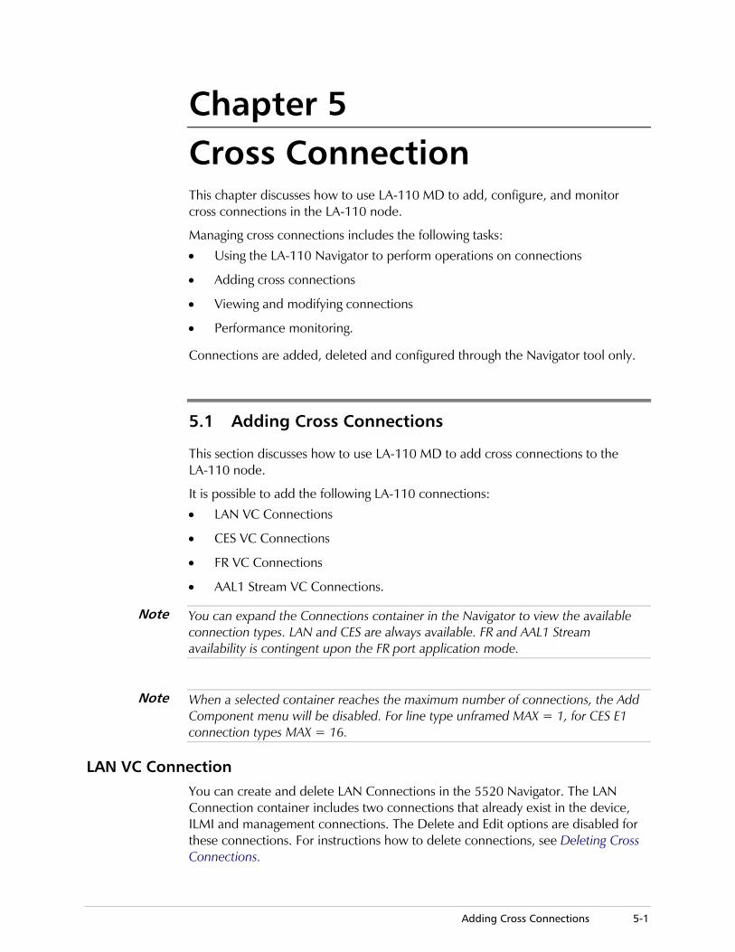
Adding Cross Connections 5-1
Chapter 5 Cross Connection This chapter discusses how to use LA-110 MD to add, configure, and monitor cross connections in the LA-110 node.
Managing cross connections includes the following tasks:
• Using the LA-110 Navigator to perform operations on connections
• Adding cross connections
• Viewing and modifying connections
• Performance monitoring.
Connections are added, deleted and configured through the Navigator tool only.
5.1 Adding Cross Connections
This section discusses how to use LA-110 MD to add cross connections to the LA-110 node.
It is possible to add the following LA-110 connections:
• LAN VC Connections
• CES VC Connections
• FR VC Connections
• AAL1 Stream VC Connections.
You can expand the Connections container in the Navigator to view the available connection types. LAN and CES are always available. FR and AAL1 Stream availability is contingent upon the FR port application mode.
When a selected container reaches the maximum number of connections, the Add Component menu will be disabled. For line type unframed MAX = 1, for CES E1 connection types MAX = 16.
LAN VC Connection You can create and delete LAN Connections in the 5520 Navigator. The LAN Connection container includes two connections that already exist in the device, ILMI and management connections. The Delete and Edit options are disabled for these connections. For instructions how to delete connections, see Deleting Cross Connections.
Note
Note

Chapter 5 Cross Connection 5620 Model Descriptor for LA-110 User’s Manual
5-2 Adding Cross Connections
To add a LAN VCL cross connection:
1. In the Navigator, double-click the Connections container to display the LAN VC Connection.
2. Select the LAN VC Connections container, right-click and select Add Component > Cross Connection > Add LAN VCL.
Figure 5-1. Add LAN VCL Connection
3. Fill in the fields, as described in Table 5-1.
4. Click <Save> to save the changes.
Table 5-1. Add LAN VCL Connection Parameters
Parameter Valid Ranges
VPI The VPI value of the VCL.
0…31
VCI The VCI value of the VCL.
0..255
Traffic Descriptor
Identifies the row in the Traffic Descriptor (TD) Table which applies to the transmit direction of the VCL.
1…200 (values available as defined in TD table)
Continuity Check
The VCC admin status.
Off Two Way (down), On Two Way (up), On-source, On-sink
Read-only
CES VC Connection To add a CES VC cross connection:
1. Verify bundles are associated with timeslots (see the section, "Bundles Configuration" (for CES E1 ports) in the "Port Configuration and Monitoring" chapter.)

5620 Model Descriptor for LA-110 User’s Manual Chapter 5 Cross Connection
Adding Cross Connections 5-3
2. In the Navigator, double-click on Connections container to display the CES VC Connection option.
3. Select CES VC Connection, right-click and select Add Component > Cross Connection > CES Connection.
Figure 5-2. Add CES Connection
4. Fill in the fields, as described in Table 5-2.
5. Click <Save> to save the changes.

Chapter 5 Cross Connection 5620 Model Descriptor for LA-110 User’s Manual
5-4 Adding Cross Connections
Table 5-2. Add CES Connection Parameters
Parameter Valid Ranges
ATM Endpoint:
VPI The VPI value of the ATM endpoint.
0…31
VCI The VCI value of the ATM endpoint
0…255
Continuity Check
The VCC admin status.
Off Two Way (down), On Two Way (up), On-source, On-sink
Read-only
Signaling Yes, No
If AAL1 type is transparent, set to No and disabled signaling.
CES E1:
Line Type E1, E1-CRC, E1-MF, E1-CRC-MFE1 Unframed
Bundle Bundle 1 to Bundle 31 for E1
AAL1 Type CES, DBCES, Transparent
Parity Off, On
Disabled if AAL1 Type is Transparent
Used Bytes Per Cell
Rx Specifies the number of payload bytes to be expected in the cells received by the new connection.
Remaining bytes are assumed to be padding bytes and are therefore discarded.
Tx Specifies the number of payload bytes to be inserted in the cells before transmitting it. After the specified number of payload is collected, the remaining bytes in the cell are filled with padding, and the cell is immediately transmitted toward the network.
This parameter enables the user to reduce the delay caused by the cell filling in applications that cannot tolerate long delays.
The following fields are disabled if AAL1 Type is not DBCES.
DBCES Parameters
Signaling Type E&M/PLAR, FXO-Loop Start, FXS-Loop Start, FXO-Ground Start, FXS-Ground Start, R2, Other
The following fields are enabled only if Signaling Type is Other.
All bits must be 0 for CES connection
Tx A Bit 0, 1, or X
Tx B Bit 0, 1, or X
Rx A Bit 0, 1, or X
Rx B Bit 0, 1, or X

5620 Model Descriptor for LA-110 User’s Manual Chapter 5 Cross Connection
Adding Cross Connections 5-5
FR VC Connection To add a Data FR VC cross connection:
1. In the Navigator, double-click the Connections container to display the FR VC Connection option.
2. Select FR VC Connection, right-click and select Add Component > Cross Connection > FR Connection.
Figure 5-3. Add FR VC Connection
3. Fill in the fields, as described in Table 5-3.
4. Click <Save> to save the changes.
Table 5-3. Add FR VC Connections Parameters
Parameter Valid Ranges
VPI The VPI value of the ATM end point.
0..31
VCI The VCI value of the ATM end point.
0..255
Traffic Descriptor
Identifies the row in the Traffic Descriptor (TD).
1…200 (values available as defined in TD table)

Chapter 5 Cross Connection 5620 Model Descriptor for LA-110 User’s Manual
5-6 Adding Cross Connections
Table 5-3. Add FR VC Connections Parameters (Cont.)
Parameter Valid Ranges
Continuity Check
The VCC admin status.
Off Two Way (down), On Two Way (up), On-source, On-sink
Read-only
FR:
DLCI 16–991
Leaf XC Yes, No
IWF The IWF mode.
1…42
For each ID, the corresponding type will appear.
SSCS DLCI Allows configuration of the FR SSCS DLCI that is transferred to the remote FR unit 16–991, 1022
This parameter is only available when IWF (Function Mode) is set to Network.
AAL1 Stream VC Connection To add an AAL1 Stream VC cross connection:
1. In the Navigator, double-click the Connections container to display the AAL1 Stream VC Connection option.
2. Select AAL1 Stream VC Connection, right-click and select Add Component > Cross Connection > AAL1 Stream Connection.
Figure 5-4. AAL1 Stream VC Connection

5620 Model Descriptor for LA-110 User’s Manual Chapter 5 Cross Connection
Adding Cross Connections 5-7
3. Fill in the fields, as described in Table 5-4.
4. Click <Save> to save the changes.
Table 5-4. AAL1 Stream VC Connections Parameters
Parameter Valid Ranges/Remarks
ATM
VPI The VPI value of the ATM end point.
0…31
VCI The VCI value of the ATM end point.
0…255
AAL1 Stream
Rx Bytes per Cell
10…47 (default)
Tx Bytes per Cell
10…47 (default)
Connection Type
Unstructured, Structured
The values depend on the port data Rate (64..2048 Kbps) and on the RTS DCD (on, off, or not applicable)
Only “Structured (Signals Transported)” is visible, when the RTS DCD is 1 (ignore signal) or 2 (obey signal). For other values of RTS DCD, display values depends on Rate = 64 K (r64KBps) possible values are:
• Structured with Pointer,
• Structured without Pointer
• Structured (Signals Transported)
For Rate <> 64 Kbps, possible values are:
• Unstructured,
• Structured,
• Structured (Signals Transport
Pointer Parity Not Applicable, Off, On
List of possible values depend on Connection Type, as follows:
• Unstructured: NA,
• Structured: ON, OFF
• Structure with Pointer: ON, OFF
• Structured without Pointer: NA
• Structured (Signals Transported): NA
Continuity Check
The VCC admin status.
Off Two Way (down), On Two Way (up), On-source, On-sink
Read-only

Chapter 5 Cross Connection 5620 Model Descriptor for LA-110 User’s Manual
5-8 Configuring Cross Connections
5.2 Configuring Cross Connections
The Navigator allows you to configure cross connections in the LA-110 node.
LAN VC Connections Basic tasks include viewing and configuring:
• Connection Info
• VCL connections
• Loopback testing.
Connection Information
To view LAN VC connection information parameters:
• In the Navigator, select the LAN VC Connections container, right-click and select Configure > Connections Info.
Figure 5-5. LAN VC Connections Info
Table 5-5. LAN VC Connections Info Parameters
Parameter Valid Ranges/Remarks
VPI The VPI value of the VC.
0…31
Read-only
VCI The VCI value of the VC.
0…255
Read-only
Operation Status Up, Down

5620 Model Descriptor for LA-110 User’s Manual Chapter 5 Cross Connection
Configuring Cross Connections 5-9
Table 5-5. LAN VC Connections Info Parameters (Cont.)
Parameter Valid Ranges/Remarks
Traffic Descriptor 1…200
Read-only
Continuity Check The VCC admin status.
Off Two Way (down), On Two Way (up), On-source, On-sink
Read-only
Last Change This field indicates the time of the last change on the port.
Read-only
The following fields are available only for Bridge VLAN Aware.
Connected To Bridge Port #, Not Connected
Priorities 0…7
VCL Connection
To edit a LAN VCL cross connection:
1. In the Navigator, select the LAN Connection, right-click and select Configure > Edit LAN VCL Connection.
The Edit LAN VCL Connection form opens in which you can connect the bridge port to the VCL and assign VLAN Priority to the connection. (This is only applicable to VLAN Aware mode.) An ATM Bridge Port can be connected to up to three VCLs according to the following conditions: Each connection includes a VLAN Priority, which can be one or more
values from a specified VLAN Priority Range (0…7).
Two connections of the same ATM Bridge Port CANNOT share the same VLAN Priority.

Chapter 5 Cross Connection 5620 Model Descriptor for LA-110 User’s Manual
5-10 Configuring Cross Connections
Figure 5-6. Edit VCL Connection
2. Fill in the fields, as described in Table 5-6.
3. Select the ATM Bridge Port and VLAN Priority.

5620 Model Descriptor for LA-110 User’s Manual Chapter 5 Cross Connection
Configuring Cross Connections 5-11
Table 5-6. Edit VCL Connection Parameters
Parameter Valid Ranges/Remarks
VPI The VPI value of the VCL.
0…31
Read-only
VCI The VCI value of the VCL.
0…255
Read-only
Traffic Descriptor 1…200
Continuity Check The VCC admin status.
Off Two Way (down), On Two Way (up), On-source, On-sink
Operational Status
Up, Down
The following fields are available only for Bridge - VLAN Aware.
Connected To
ATM Bridge Port 1…existing ATM Bridge port number, Not Connected
VLAN Priority
VLAN Priority Enable
Select: enables you to select any priority
All: all priorities are selected. (Selectable if selected Bridge Port is not connected to any VCL or if selected Bridge Port is connected only to the VCL that is being edited now)
None: this value is not selectable and will be displayed when “Not Connected” selected in “ATM Bridge Port” field
Priorities 0…7 Free, On, N/A, Used.
If this priority is assigned to the selected VCL The value is “On”.
If this priority is assigned to another VCL other then the selected VCL Then the value is “Used – VPI/VCI “ where VPI/VCI are of the assigned VCL.
If this priority is not assigned to any of the existing VCLs The value is “Free”.
Only “Free” and “On” are selectable values
The value “N/A” is not selectable and represents a new connection where the VLAN Priority field value is “All”.
Loopback Testing
To configure LAN VC connection loopback testing:
1. In the Navigator, select the LAN VC Connections container, right-click and select Configure > Loopback Test.

Chapter 5 Cross Connection 5620 Model Descriptor for LA-110 User’s Manual
5-12 Configuring Cross Connections
Figure 5-7. LAN VC Connection – Loopback Test
2. Fill in the fields, as described in Table 5-7.
3. Click <Save> to save the changes. The result of Signal Mode test appears six seconds after the "Save" button is clicked.

5620 Model Descriptor for LA-110 User’s Manual Chapter 5 Cross Connection
Configuring Cross Connections 5-13
Table 5-7. LAN VC Connection – Loopback Test Parameters
Parameter Remarks
VPI The VPI value of the VC.
0…31
Read-only
VCI The VCI value of the VC.
0…255
Read-only
Loopback Test
Mode Single, Periodic
Single Mode
Result OK, Failed
Periodic Mode
Loopback Failure Indication
Disabled (default), Enabled
Loopback Failure Threshold
1 (default)…16
Enabled only if Loopback Fail Indication is enabled
Loopback Test Status
Activates a loopback test on the specified port.
None, Remote Loopback (RLB), Local Loopback (LLB)
Action Activates a loopback test on the specified port.
Activate Test, Stop Test
CES VC Connections Basic tasks include viewing and configuring:
• Connection Info
• Activating/deactivating connections
• Loopback testing.
Connection Information
To view CES VC connection information parameters:
• In the Navigator, select the CES VC Connections container, right-click and select Configure > Connections Info.

Chapter 5 Cross Connection 5620 Model Descriptor for LA-110 User’s Manual
5-14 Configuring Cross Connections
Figure 5-8. CES VC Connections Info
For CES there are three possible tables that depend on port Line Type and AAL1 Type.
Table 5-8. Framed CES VC Connections Info Parameters
Parameter Valid Ranges/Remarks
VPI The VPI value of the VC.
0…31
Read-only
VCI The VCI value of the VC.
0…255
Read-only
AAL1 Type CES, DBCES
Read-only
Operation Status Up, Down
Read-only
Bundle Used to assist the NMS in selecting a value for the bundle index.
1-31
Read-only
Continuity Check The VCC admin status.
Off Two Way (down), On Two Way (up), On-source, On-sink
Read-only
Rx 10…47
Read-only

5620 Model Descriptor for LA-110 User’s Manual Chapter 5 Cross Connection
Configuring Cross Connections 5-15
Table 5-8. Framed CES VC Connections Info Parameters (Cont.)
Parameter Valid Ranges/Remarks
Tx 0, 1, X
Read-only
Parity Off, On
Read-only
Signaling The signaling mode
Read-only
Signaling Type The Signaling type
Read-only
Tx A 0, 1, X
Read-only
Tx B 0, 1, X
Read-only
Rx A 0, 1, X
Read-only
Rx B 0, 1, X
Read-only
Last Change This field indicates the time of the last change on the port.
Read-only
Table 5-9. Transparent CES VC Connections Info Parameters
Parameter Valid Ranges/Remarks
VPI The VPI value of the VC.
0…31
Read-only
VCI The VCI value of the VC.
0…255
Read-only
AAL1 Type Transparent
Read-only
Operation Status Up, Down
Read-only

Chapter 5 Cross Connection 5620 Model Descriptor for LA-110 User’s Manual
5-16 Configuring Cross Connections
Table 5-9. Transparent CES VC Connections Info Parameters (Cont.)
Parameter Valid Ranges/Remarks
Bundle Used to assist the NMS in selecting a value for the bundle index.
1-31
Read-only
Continuity Check The VCC admin status.
Off Two Way (down), On Two Way (up), On-source, On-sink
Read-only
Rx 10…47
Read-only
Tx 10…47
Read-only
Parity Off, On
Read-only
Signaling The signaling mode
Read-only
Last Change This field indicates the time of the last change on the port.
Read-only
Table 5-10. Unframed CES VC Connections Info Parameters
Parameter Valid Ranges/Remarks
VPI The VPI value of the VC.
0…31
Read-only
VCI The VCI value of the VC.
0…255
Read-only
AAL1 Type CES, DBCES, Transparent
Read-only
Operation Status Up, Down
Read-only
Note: AAL1 Type can only be transparent in the case of an Unframed CES VC connection.

5620 Model Descriptor for LA-110 User’s Manual Chapter 5 Cross Connection
Configuring Cross Connections 5-17
Table 5-10. Unframed CES VC Connections Info Parameters (Cont.)
Parameter Valid Ranges/Remarks
Bundle Used to assist the NMS in selecting a value for the bundle index.
1-31
Read-only
Continuity Check The VCC admin status.
Off Two Way (down), On Two Way (up), On-source, On-sink
Read-only
Rx 10…47
Read-only
Tx 10…47
Read-only
Last Change This field indicates the time of the last change on the port.
Read-only
Activating/Deactivating Connection
To activate/deactivate CES VC connections:
1. In the Navigator, select the necessary CES VC connection, right-click and select Configure > Activate/Deactivate Connection.
Figure 5-9. CES VC Activate/Deactivate Connections

Chapter 5 Cross Connection 5620 Model Descriptor for LA-110 User’s Manual
5-18 Configuring Cross Connections
2. Fill in the fields, as described in Table 5-11.
3. Click <Save> to save the changes.
Table 5-11. Activate/Deactivate CES VC Connections Parameters
Parameter Valid Ranges/Remarks
ATM Endpoint
VPI The VPI value of the VC.
0…31
Read-only
VCI The VCI value of the VC.
0…255
Read-only
CES Endpoint
Bundle ID Used to assist the NMS in selecting a value for the bundle index.
1-31
Read-only
Connection
Connection Status
Up, Down
Loopback Testing
To configure CES VC connection loopback testing:
1. In the Navigator, select the CES VC Connections container, right-click and select Configure > Loopback Test.

5620 Model Descriptor for LA-110 User’s Manual Chapter 5 Cross Connection
Configuring Cross Connections 5-19
Figure 5-10. CES VC Connection – Loopback Test
2. Fill in the fields, as described in Table 5-12.
3. Click <Save> to save the changes. The result of the Signal Mode test appears six seconds after the "Save" button is pressed.

Chapter 5 Cross Connection 5620 Model Descriptor for LA-110 User’s Manual
5-20 Configuring Cross Connections
Table 5-12. CES VC Connection – Loopback Test Parameters
Parameter Remarks
VPI The VPI value of the VC.
0…31
Read-only
VCI The VCI value of the VC.
0…255
Read-only
Loopback Test
Mode Single, Periodic
Single Mode
Result OK, Failed
Periodic Mode
Loopback Failure Indication
Disabled (default), Enabled
Loopback Failure Threshold
1 (default)…16
Enabled only if Loopback Fail Indication is enabled
Loopback Test Status
Activates a loopback test on the specified port.
Off, Running
Action Activates a loopback test on the specified port.
Activate Test, Stop Test
FR VC Connections Basic tasks include viewing and configuring:
• Connection Info
• Activating/deactivating connections
• Loopback testing.
Connection Information
This menu will be enable only when application mode = FR.
To view FR VC connection information parameters:
• In the Navigator, select the FR VC Connections container, right-click and select Configure > Connections Info.
Note

5620 Model Descriptor for LA-110 User’s Manual Chapter 5 Cross Connection
Configuring Cross Connections 5-21
Figure 5-11. FR VC Connections Info
Table 5-13. FR VC Connections Info Parameters
Parameter Valid Ranges/Remarks
ID The row/index number.
VPI The VPI value of the VC.
0…31
Read-only
VCI The VCI value of the VC.
0…255
Read-only
SSCS DLCI Read-only
Operation Status Up, Down
Read-only
IWF 0…42
Read-only
IWF Type Network, Service
Read-only
Traffic Descriptor 1…200
Read-only
Continuity Check On, Off, Send Only, Receive Only
Read-only
Last Change This field indicates the time of the last change on the port.
Read-only
Activating/Deactivating Connection
To activate/deactivate FR VC connections:
1. In the Navigator, select the necessary FR VC connection, right-click and select Configure > Activate/Deactivate Connection.

Chapter 5 Cross Connection 5620 Model Descriptor for LA-110 User’s Manual
5-22 Configuring Cross Connections
Figure 5-12. FR VC Activate/Deactivate Connections
2. Fill in the fields, as described in Table 5-14.
3. Click <Save> to save the changes.
Table 5-14. Activate/Deactivate FR VC Connections Parameters
Parameter Valid Ranges/Remarks
ATM Endpoint
VPI The VPI value of the VC.
0…31
Read-only
VCI The VCI value of the VC.
0…255
Read-only
FR Endpoint
DLCI 16…991
Read-only
Connection
Operational Status
Up, Down
Loopback Testing
To configure FR VC connection loopback testing:
1. In the Navigator, select the FR VC Connections container, right-click and select Configure > Loopback Test.

5620 Model Descriptor for LA-110 User’s Manual Chapter 5 Cross Connection
Configuring Cross Connections 5-23
Figure 5-13. FR VC Connection – Loopback Test
2. Fill in the fields, as described in Table 5-15.
3. Click <Save> to save the changes. The result of the Signal Mode test appears six seconds after the "Save" button is pressed.

Chapter 5 Cross Connection 5620 Model Descriptor for LA-110 User’s Manual
5-24 Configuring Cross Connections
Table 5-15. FR VC Connection – Loopback Test Parameters
Parameter Remarks
VPI The VPI value of the VC.
VCI The VCI value of the VC.
Read-only
Loopback Test
Mode Single, Periodic
Single Mode
Result OK, Failed
Read-only
Periodic Mode
All fields in this section will be enable only if Mode=Single.
Loopback Failure Indication
Disabled (default), Enabled
Loopback Failure Threshold
1 (default)…16
Enabled only if Loopback Fail Indication is enabled
Loopback Test Status
Activates a loopback test on the specified port.
Off, Running
Read-only
Action Activates a loopback test on the specified port.
Loopback Test, Stop Test
AAL1 Stream VC Connections Basic tasks include viewing and configuring:
• Connection information
• Activate/Deactivate connection
• Loopback testing.
Connection Information
To view AAL1 Stream VC connection information parameters:
• In the Navigator, select the AAL1 Stream VC Connections container, right-click and select Configure > Connections Info.
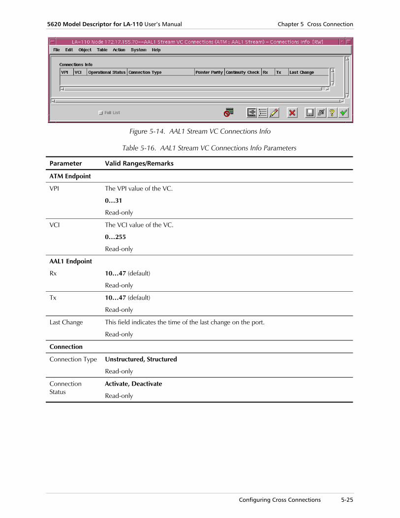
5620 Model Descriptor for LA-110 User’s Manual Chapter 5 Cross Connection
Configuring Cross Connections 5-25
Figure 5-14. AAL1 Stream VC Connections Info
Table 5-16. AAL1 Stream VC Connections Info Parameters
Parameter Valid Ranges/Remarks
ATM Endpoint
VPI The VPI value of the VC.
0…31
Read-only
VCI The VCI value of the VC.
0…255
Read-only
AAL1 Endpoint
Rx 10…47 (default)
Read-only
Tx 10…47 (default)
Read-only
Last Change This field indicates the time of the last change on the port.
Read-only
Connection
Connection Type Unstructured, Structured
Read-only
Connection Status
Activate, Deactivate
Read-only

Chapter 5 Cross Connection 5620 Model Descriptor for LA-110 User’s Manual
5-26 Configuring Cross Connections
Activating/Deactivating Connection
To activate/deactivate AAL1 Stream VC connections:
1. In the Navigator, select the necessary AAL1 Stream VC connection, right-click and select Configure > Activate/Deactivate Connection.
Figure 5-15. AAL1 Stream VC Activate/Deactivate Connections
2. Fill in the fields, as described in Table 5-17.
3. Click <Save> to save the changes.
Table 5-17. Activate/Deactivate AAL1 Stream VC Connections Parameters
Parameter Valid Ranges/Remarks
ATM Endpoint
VPI The VPI value of the VC.
0…31
Read-only
VCI The VCI value of the VC.
0…255
Read-only
Operational Status
Up, Down
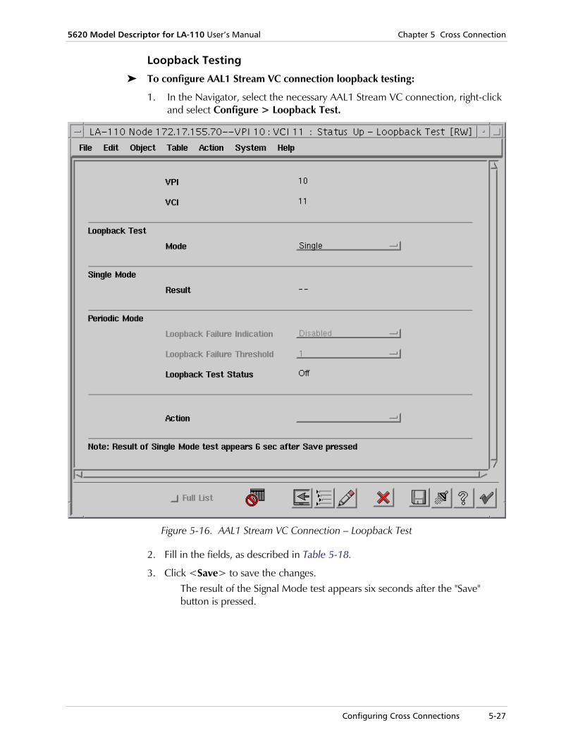
5620 Model Descriptor for LA-110 User’s Manual Chapter 5 Cross Connection
Configuring Cross Connections 5-27
Loopback Testing
To configure AAL1 Stream VC connection loopback testing:
1. In the Navigator, select the necessary AAL1 Stream VC connection, right-click and select Configure > Loopback Test.
Figure 5-16. AAL1 Stream VC Connection – Loopback Test
2. Fill in the fields, as described in Table 5-18.
3. Click <Save> to save the changes. The result of the Signal Mode test appears six seconds after the "Save" button is pressed.

Chapter 5 Cross Connection 5620 Model Descriptor for LA-110 User’s Manual
5-28 Performance Monitoring
Table 5-18. AAL1 Stream VC Connection – Loopback Test Parameters
Parameter Remarks
VPI The VPI value of the VC.
0…31
Read-only
VCI The VCI value of the VC.
0…255
Read-only
Loopback Test
Mode Single, Periodic
Single Mode
Result OK, Failed
Read-only
Periodic Mode
All fields in this section will be enabled only if Mode=Single.
Loopback Failure Indication
Disabled (default), Enabled
Loopback Failure Threshold
1 (default)…16
Enabled only if Loopback Fail Indication is enabled
Loopback Test Status
Activates a loopback test on the specified port.
Off, Running
Read-only
Action Activates a loopback test on the specified port.
Loopback Test, Stop Test
5.3 Performance Monitoring
The LA-110 Navigator application allows you to monitor cross connections and related performance statistics. Basic tasks include viewing:
• OAM loopback statistics
• CES VC Connection – OAM loopback statistics
• Data FR - OAM loopback statistics
• Data AAL1 - OAM loopback statistics.
All of the Performance Monitoring parameters, as shown in the tables below, are read-only.
Note

5620 Model Descriptor for LA-110 User’s Manual Chapter 5 Cross Connection
Performance Monitoring 5-29
Viewing VC Connection OAM Loopback Statistics In the OAM loopback test the device sends LB cell every 5 seconds. If the cell does not return within 5 seconds the test is defined as a failed one.
In the LA-110 Navigator, you can view OAM loopback statistics for any VC Connection, including LAN, CES, FR, and AAL1 Stream, and any related sub-connections (such as VPI ILMI for LAN VCs, etc.).
1. In the Navigator, double-click the Connections container to display the connection type options.
2. Select the relevant connection (LAN VC, CES VC, FR VC, or AAL1 Stream VC), right-click and select Monitor > Statistics > OAM Loopback Statistics.
The relevant OAM Loopback Statistics window opens.
Figure 5-17. VC Connection - OAM Loopback Statistics Window

Chapter 5 Cross Connection 5620 Model Descriptor for LA-110 User’s Manual
5-30 Deleting Cross Connections
Table 5-19. OAM Loopback Statistics Parameters
Parameter Remarks
VPI The VPI value of the VC.
Read-only
VCI The VPI value of the VC.
Read-only
Rx Loopback Requests
Total number of loopback requests received by the device on a VC.
Read-only
Rx Loopback Responses
Total number of loopback responses that were received as a result of loopback transmitted by the device.
Read-only
Tx Loopback Requests
Total number of loopback requests transmitted by the device on a VC.
Read-only
Tx Loopback Responses
Total number of loopback responses transmitted by the device on a VC.
Read-only
Successful Loopback
Total number of loopbacks that were requested by the device and for which there was a response.
Read-only
Failed Loopback
Total number of loopbacks that were requested by the device and for which there was no response
Read-only
Minimum Delay (µsec)
The minimum delay.
Read-only
Average Delay (µsec)
The average delay without including lost cells.
Read-only
Maximum Delay (µsec)
The maximum delay without including lost cells.
Read-only
5.4 Deleting Cross Connections
In the Navigator, you can manually delete selected cross connections.
To delete a cross connection
• In the Navigator, select the relevant Connection object(s), and on the Object menu, click <Delete>.
The selected Connection object(s) is deleted.
It is also possible to simultaneously delete (up to 10) multiple cross connections by selecting them and following the above steps.

Configuring and Monitoring Links and Paths 6-1
Chapter 6 Path Management This chapter discusses how to use the LA-110 Module Descriptor to configure links and paths, to connect ports of LA-110 devices.
Path management is an easy and quick method to acquire end-to-end connectivity between two given endpoints.
A link can be created between two equipment ports in the network. An LA-110 endpoint can be linked to another 5620 managed endpoint with the same features.
A path can be created between any of the other three modules of the LA-110 to another managed endpoint in the 5620 SNMP map. The path endpoints do not have to be from the same type. For example, one path endpoint can be ATM and the other can be LAN.
Path management includes the following tasks:
• Configuring and Monitoring Links and Paths
• Configuring and Monitoring ATM VCC Paths.
6.1 Configuring and Monitoring Links and Paths
LA-110 MD allows you to configure and monitor new Links and new Paths at the network level.
A Link is a physical connection between two devices, whereas a Path is a logical connection between two ports. Before you can create a path, you must first create a link.
LA-110 allows you to create links between SHDSL ports.
Configuring SHDSL Links You can configure a link between two SHDSL ports of ATM modules. To create a link between SHDSL ports of two LA-110s, you need to connect the SDHSL ports to a central SDHSL DSLAM. You cannot create a direct link between SHDSL ports of different LA-110 devices.
To configure a full link between two SHDSL ports:
1. Right-click on the Entire Network map (without selecting any objects), and from the shortcut menu, select Create > Physical Links > Full.

Chapter 6 Path Management 5620 Model Descriptor for LA-110 User’s Manual
6-2 Configuring and Monitoring Links and Paths
Figure 6-1. New Full Link Dialog Box
2. On the Entire Network map, double-click an LA-110 Node icon to open the LA-110 Shelf View.
Figure 6-2. LA-110 Node Shelf View
3. Double-click the SHDSL port to focus on it – to open its zoom view.
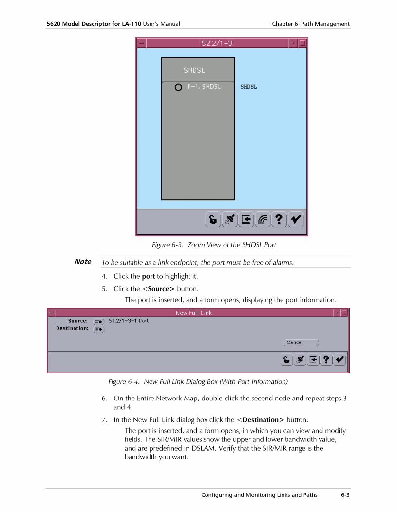
5620 Model Descriptor for LA-110 User’s Manual Chapter 6 Path Management
Configuring and Monitoring Links and Paths 6-3
Figure 6-3. Zoom View of the SHDSL Port
To be suitable as a link endpoint, the port must be free of alarms.
4. Click the port to highlight it.
5. Click the <Source> button. The port is inserted, and a form opens, displaying the port information.
Figure 6-4. New Full Link Dialog Box (With Port Information)
6. On the Entire Network Map, double-click the second node and repeat steps 3 and 4.
7. In the New Full Link dialog box click the <Destination> button. The port is inserted, and a form opens, in which you can view and modify fields. The SIR/MIR values show the upper and lower bandwidth value, and are predefined in DSLAM. Verify that the SIR/MIR range is the bandwidth you want.
Note

Chapter 6 Path Management 5620 Model Descriptor for LA-110 User’s Manual
6-4 Configuring and Monitoring Links and Paths
Figure 6-5. New Full Link Dialog Box
8. Enter the relevant information for the appropriate attributes.
9. Click <Save>. A line denoting a link appears on the Entire Network Map (Figure 6-6).
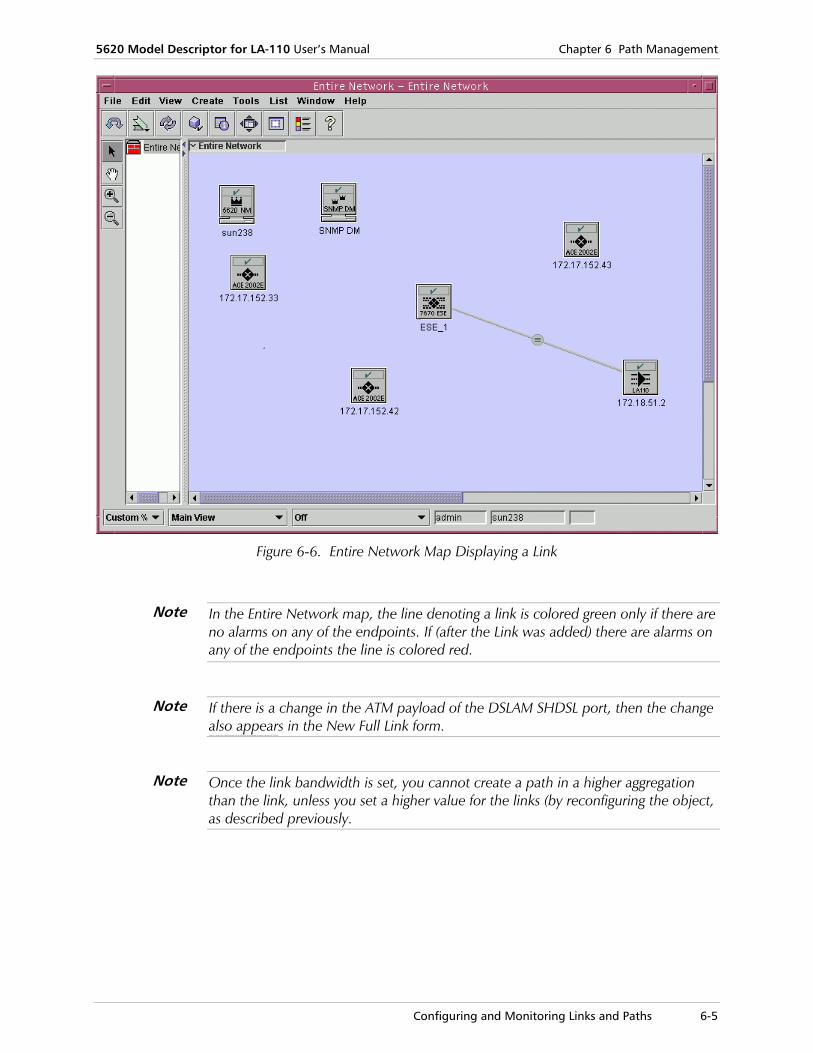
5620 Model Descriptor for LA-110 User’s Manual Chapter 6 Path Management
Configuring and Monitoring Links and Paths 6-5
Figure 6-6. Entire Network Map Displaying a Link
In the Entire Network map, the line denoting a link is colored green only if there are no alarms on any of the endpoints. If (after the Link was added) there are alarms on any of the endpoints the line is colored red.
If there is a change in the ATM payload of the DSLAM SHDSL port, then the change also appears in the New Full Link form. If there is a change in the ATM payload of the DSLAM SHDSL port, then the change also appears in the New Full Link form.
Once the link bandwidth is set, you cannot create a path in a higher aggregation than the link, unless you set a higher value for the links (by reconfiguring the object, as described previously.
Note
Note
Note

Chapter 6 Path Management 5620 Model Descriptor for LA-110 User’s Manual
6-6 Configuring and Monitoring ATM VCC Paths
6.2 Configuring and Monitoring ATM VCC Paths
LA-110 MD allows you to configure and monitor ATM VCC paths between the following endpoints:
• Ethernet ports
• E1 CES ports
• Data FR / AAL1 Stream ports.
LAN to LAN Paths To configure a path between two LAN (Ethernet) ports:
1. Right-click on the Entire Network Map and select Create > ATM and TDM > Paths > ATM > VCC.
The new ATM VCC path form opens, in which you can specify the path endpoints.
Figure 6-7. New ATM VCC Path
2. On the Entire Network Map, double-click an LA-110 icon to open the LA-110 Node shelf view (Figure 6-2).
3. Double-click the LAN port to focus on it – to open its zoom view.
Figure 6-8. Zoom View of LAN Port
4. Select the LAN port to highlight it.
5. In the New ATM VCC Path, click the <Path-endpoint A> button to assign the port as an endpoint.

5620 Model Descriptor for LA-110 User’s Manual Chapter 6 Path Management
Configuring and Monitoring ATM VCC Paths 6-7
Figure 6-9. New ATM VCC Path Showing Path Endpoint A
6. In the Entire Network map, double-click the second LA-110 node to open its Shelf View, and repeat steps 4 and 5 to assign the port as the second endpoint (B).
The New ATM VCC Path form opens, displaying General parameters.
Figure 6-10. New ATM VCC Path Showing General Parameters
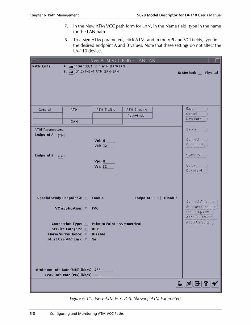
Chapter 6 Path Management 5620 Model Descriptor for LA-110 User’s Manual
6-8 Configuring and Monitoring ATM VCC Paths
7. In the New ATM VCC path form for LAN, in the Name field, type in the name for the LAN path.
8. To assign ATM parameters, click ATM, and in the VPI and VCI fields, type in the desired endpoint A and B values. Note that these settings do not affect the LA-110 device.
Figure 6-11. New ATM VCC Path Showing ATM Parameters
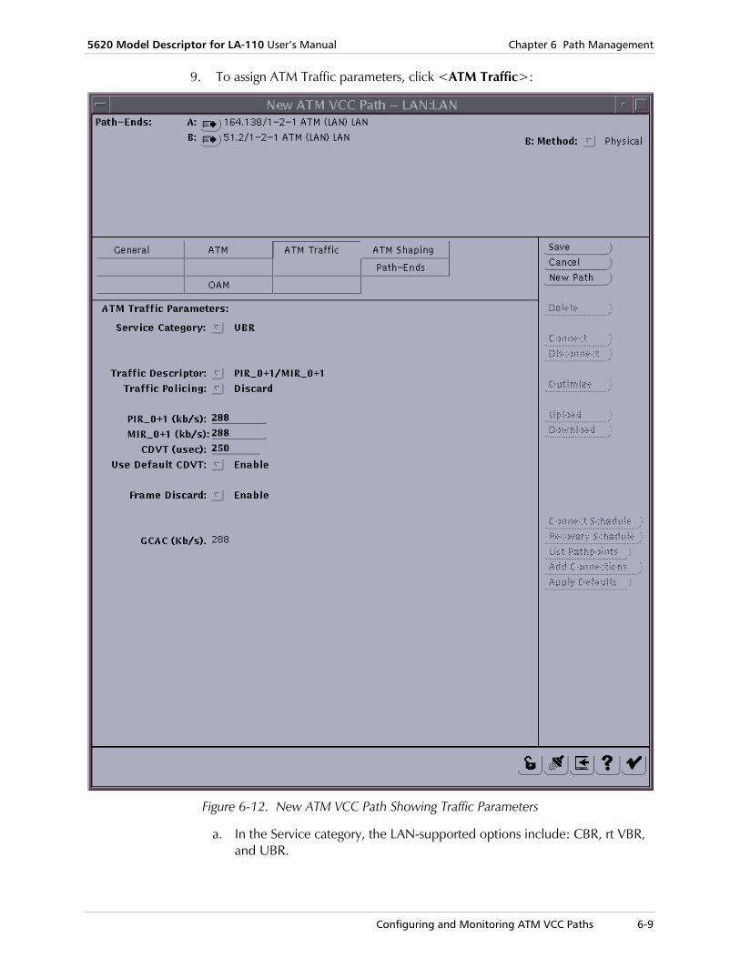
5620 Model Descriptor for LA-110 User’s Manual Chapter 6 Path Management
Configuring and Monitoring ATM VCC Paths 6-9
9. To assign ATM Traffic parameters, click <ATM Traffic>:
Figure 6-12. New ATM VCC Path Showing Traffic Parameters
a. In the Service category, the LAN-supported options include: CBR, rt VBR, and UBR.
Chapter 6 Path Management 5620 Model Descriptor for LA-110 User’s Manual
6-10 Configuring and Monitoring ATM VCC Paths
b. In the PIR (peak Information rate) and MIR (Minimum Information Rate) fields, assign the PIR and MIR values. Note that the PIR rate must be the same or higher than the MIR rate.
According to 5620 regulations, the UBR Service Category connection consumes a fixed share of bandwidth (BW), although in LA-110 terms, the configured BW is not guaranteed. Several UBR connections created through the 5620 NM or 5620 DM may consume the available link BW, and prevent the creation of additional CBR connections, for example. The UBR consumed BW is set by the configured MIR value, therefore it is recommended to set as low as possible an MIR rate. If setting a low MIR is not possible, RAD recommends that in case of an application, in which UBR and other service category connections are involved, the connection that will first be created will be the ones with the guaranteed bit rate (i.e. CBR). Only after that UBR connections will be created, from the 5620 NM (if BW allocation is not yet full) or from the 5620 DM if the link capacity has reached its limits. It should be noted the UBR management connections with BWs of zero are reported to the 5620.
10. Click <Save> to save the changes. The Status will show "Ready for connect".
Note

5620 Model Descriptor for LA-110 User’s Manual Chapter 6 Path Management
Configuring and Monitoring ATM VCC Paths 6-11
Figure 6-13. New ATM VCC Path Showing "Ready for Connect" Status
11. Click <Connect>.
12. To view the LAN path you have created, in Entire Network map, select the NE, right-click and select List > ATM and TDM > Paths.
The List Paths form opens.

Chapter 6 Path Management 5620 Model Descriptor for LA-110 User’s Manual
6-12 Viewing and Modifying CES Path Parameters
13. Click the <Make List> button to display the list of paths created, as shown in the following sample figure.
Figure 6-14. Sample Paths List
6.3 Viewing and Modifying CES Path Parameters
LA-110 MD allows you to view and modify CES path parameters..
The configuration made here will affect 5620 E1-CES paths that will subsequently be created.
To view and modify CES path parameters:
1. In the LA-110 Node Draw, select the system, and select Object > Configure > CES Path Parameters.
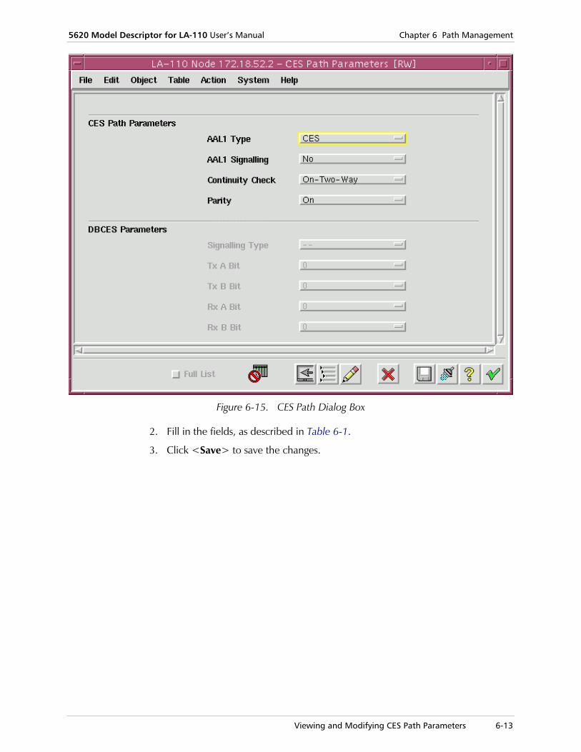
5620 Model Descriptor for LA-110 User’s Manual Chapter 6 Path Management
Viewing and Modifying CES Path Parameters 6-13
Figure 6-15. CES Path Dialog Box
2. Fill in the fields, as described in Table 6-1.
3. Click <Save> to save the changes.

Chapter 6 Path Management 5620 Model Descriptor for LA-110 User’s Manual
6-14 Viewing and Modifying CES Path Parameters
Table 6-1. CES Path Parameters
Parameters Possible Values / Remarks
CES Path Parameters
AAL1 Type Defines the type of connection that will be created
• CES: (default value) The circuit emulation service (CES) enables the transmission of constant bit rate (CBR) data over the ATM network, in accordance with the ATM Forum Circuit Emulation Service Interoperability Specification. CES uses AAL1. LA-110 supports both the structured and unstructured service modes.
• DBCES: DB-CES enables better utilization of available uplink bandwidth by using the voice channel activity information carried by the signaling bits of the port to request uplink bandwidth when the channel is active (off-hook), and release the bandwidth when the channel is idle (on-hook). The cell structure depends on the framing mode selected by the user (E1, T1 using SF framing or T1 using ESF framing).
• Transparent: This mode uses the unstructured CES mode defined in ATMF specification AF-VTOA-0078.000. In this mode, LA-110 handles the port payload as a single 64 kbps bit stream which is transparently transported over the ATM connection, without any assumptions regarding the framing.
AAL1 Signaling The CES Cas.
Yes, No
Continuity Check
The VCC admin status.
Off Two Way (down), On Two Way (up), On-source, On-sink
• Read-only
Parity Controls the use of pointer parity when using the Structured or Structured with Pointer connection type
• Off - Pointer parity generation and checking disabled.
• On (defalult value) - Pointer parity bit generation at the transmit side, and checking of parity bit for error detection at the receiving side enabled.
The field is disabled if the AAL1 type is transparent..
DBCES Parameters
The following field is disabled if the AAL1 type is not DBCES.
Signaling Type The ATM CES signaling type
E&M/PLAR, FXO-Loop Start, FXS-Loop Start, FXO-Ground Start, FXS-Ground Start, R2, Other
The following fields are enabled only if Signaling Type is Other.
Tx A Bit The ATM CES signaling AB bits
0, 1, X
Tx B Bit The ATM CES signaling AB bits
0, 1, X

5620 Model Descriptor for LA-110 User’s Manual Chapter 6 Path Management
CES to CES Paths 6-15
Table 6-1. CES Path Parameters (Cont.)
Parameters Possible Values / Remarks
Rx A Bit The ATM CES signaling AB bits
0, 1, X
Rx B Bit The ATM CES signaling AB bits
0, 1, X
6.4 CES to CES Paths
The first step in CES path creation is verifying that both CES endpoints have an identical physical layer setting. .
Unframed E1s cannot be created in the 5620 Path Creation form.
The time slot (TS) numbering in the standard 5620 shelf view is displayed below the TS row. (Note that this may be confusing because there also sequential numbering above the TS row). When the Line Type is with no multi-framing (no CAS), note that TS 31 is positioned after TS 15 and TS 16 is positioned right after it.
The CES path can be created with a minimum of three timeslots
To configure a path between two E1 CES ports:
1. Right-click on the Entire Network Map and select Create > ATM and TDM > Paths > ATM > VCC.
The new ATM VCC path form opens, in which you can specify the path endpoints.
Figure 6-16. New ATM VCC Path Dialog box
Note
Note
Note

Chapter 6 Path Management 5620 Model Descriptor for LA-110 User’s Manual
6-16 CES to CES Paths
2. On the Entire Network Map, double-click an LA-110 icon to open the LA-110 Node shelf view (Figure 6-2).
3. Double-click the CES port to focus on it – to open its zoom view.
Figure 6-17. Zoom View of CES
4. Click on the CES port to highlight it.
5. In the CES Port Level Zoom (Figure 6-17), double-click on the port. The Port Timeslot dialog box appears (Figure 6-18).
Figure 6-18. Port Timeslot Dialog Box
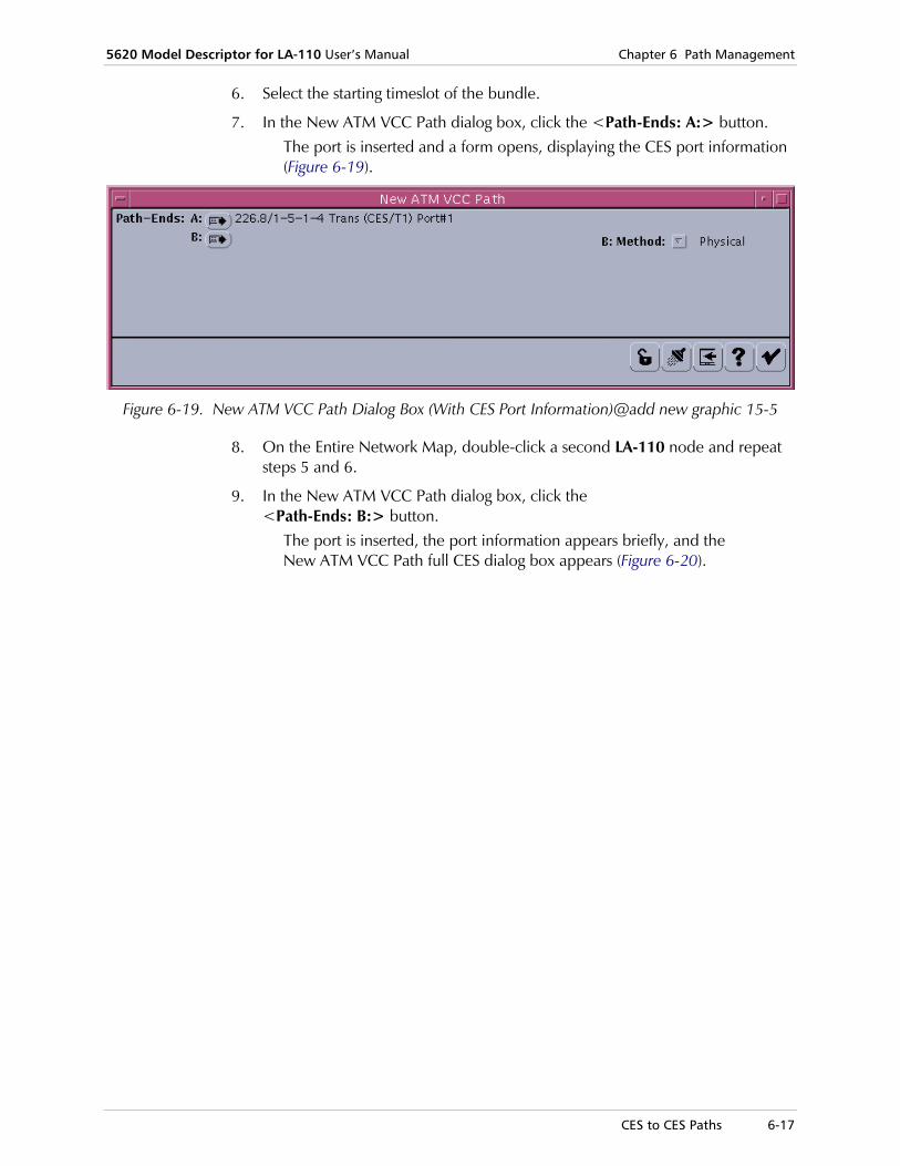
5620 Model Descriptor for LA-110 User’s Manual Chapter 6 Path Management
CES to CES Paths 6-17
6. Select the starting timeslot of the bundle.
7. In the New ATM VCC Path dialog box, click the <Path-Ends: A:> button. The port is inserted and a form opens, displaying the CES port information (Figure 6-19).
Figure 6-19. New ATM VCC Path Dialog Box (With CES Port Information)@add new graphic 15-5
8. On the Entire Network Map, double-click a second LA-110 node and repeat steps 5 and 6.
9. In the New ATM VCC Path dialog box, click the <Path-Ends: B:> button.
The port is inserted, the port information appears briefly, and the New ATM VCC Path full CES dialog box appears (Figure 6-20).

Chapter 6 Path Management 5620 Model Descriptor for LA-110 User’s Manual
6-18 CES to CES Paths
Figure 6-20. New ATM VCC Path Full CES Dialog box
10. Enter the relevant information for the appropriate attributes.
11. Click the <Channel Group> button.
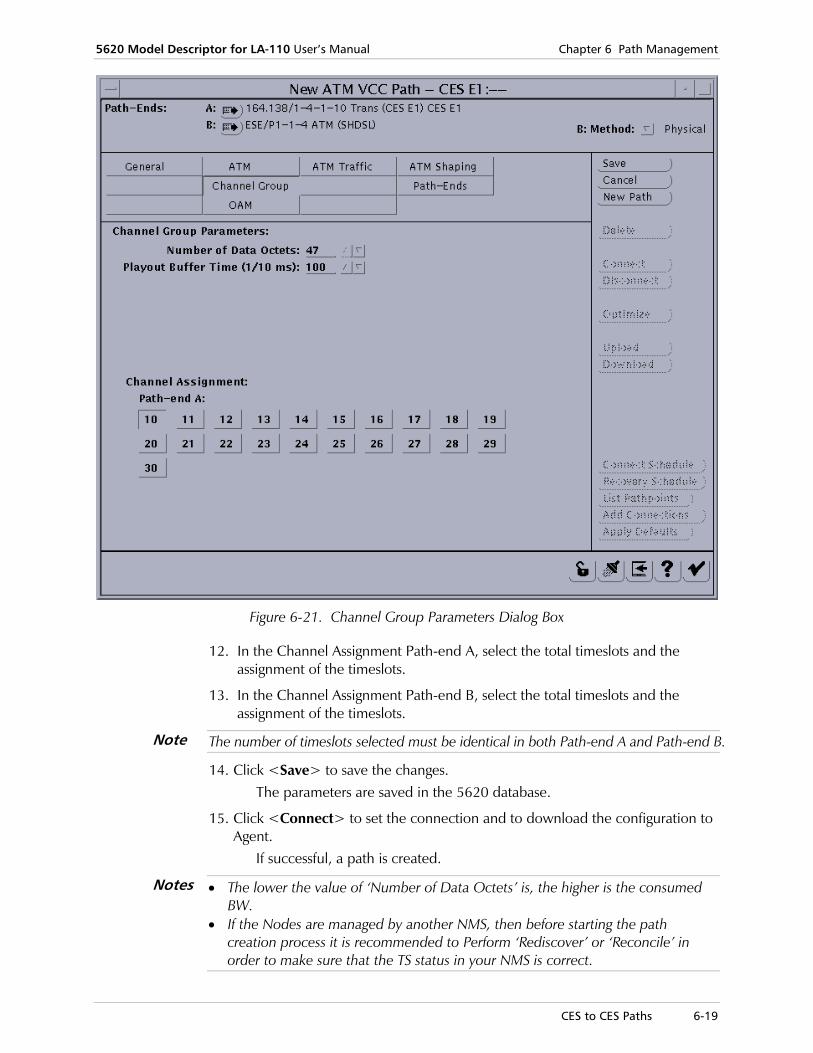
5620 Model Descriptor for LA-110 User’s Manual Chapter 6 Path Management
CES to CES Paths 6-19
Figure 6-21. Channel Group Parameters Dialog Box
12. In the Channel Assignment Path-end A, select the total timeslots and the assignment of the timeslots.
13. In the Channel Assignment Path-end B, select the total timeslots and the assignment of the timeslots.
The number of timeslots selected must be identical in both Path-end A and Path-end B.
14. Click <Save> to save the changes. The parameters are saved in the 5620 database.
15. Click <Connect> to set the connection and to download the configuration to Agent.
If successful, a path is created.
• The lower the value of ‘Number of Data Octets’ is, the higher is the consumed BW.
• If the Nodes are managed by another NMS, then before starting the path creation process it is recommended to Perform ‘Rediscover’ or ‘Reconcile’ in order to make sure that the TS status in your NMS is correct.
Note
Notes

Chapter 6 Path Management 5620 Model Descriptor for LA-110 User’s Manual
6-20 Viewing Link Information
6.5 Viewing Link Information
LA-110 MD allows you to view information for the links that appear on the Entire Network map..
To view link information:
1. On Entire Network Map, select the link, right-click and choose Object > Info.
OR
Click Open > Object.
Figure 6-22. Link Group
Viewing List of Links and Paths The 5620 NM allows you to view a list of paths and links you have created.
1. To view a list of paths (or links) you have created, in Entire Network map, select the NE, right-click and select either: List > ATM and TDM > Paths (or List > ATM and TDM > Links).
The relevant List Paths (or List Links) form opens.

5620 Model Descriptor for LA-110 User’s Manual Chapter 6 Path Management
Deleting Paths and Links 6-21
2. Click the <Make List> button to display the list of paths (or links) created, as shown in the following sample figure.
Figure 6-23. List Paths Form Showing CES Path
Figure 6-24. List Links Form Showing ESE Path
6.6 Deleting Paths and Links
In order to make subsequent connections on any NEs or DSLAMs, verify that there are no existing links or paths are on the required LA-110 endpoints. You can view the List Links form to see a list of assigned links to verify if any links need to be deleted.
In order to delete links, you have to first delete the paths that are on the links and then the links and you need to do this from both sides (endpoints) of the desired connection (from both NEs).

Chapter 6 Path Management 5620 Model Descriptor for LA-110 User’s Manual
6-22 Deleting Paths and Links
To delete paths:
1. In the List Paths form (as shown in Figure 6-23), click the <Disconnect All> button to disconnect all the paths listed. (Alternatively, you can disconnect the paths one by one.)
A confirmation message appears.
2. Click <OK> to confirm.
3. In the Paths List (see Figure 6-23), double click the path you want to delete. The Configure ATM VC Path form (see Figure 6-13) for the selected path opens.
4. In the Configure ATM VCC Path form, click the <Delete> button. The New ATM VCC Path form opens (see Figure 6-7), showing an empty form and a confirmation message that the path request is deleted.
5. To delete links, do any one of the following: In List Links form, click the <Make List> button and from the Links List,
select the relevant link row, and double-click to open the Configure Full Link form.
OR
In the Entire Network map, double-click the link to open the Link Group form where you can click in the middle area to open the Configure Full Link form.
Figure 6-25. Link Group

5620 Model Descriptor for LA-110 User’s Manual Chapter 6 Path Management
Configuring Data FR and AAL1 Stream Paths 6-23
6. Click <Delete>. A confirmation message appears.
7. Click <OK> to confirm the deletion.
The selected link is deleted.
6.7 Configuring Data FR and AAL1 Stream Paths
Configuring Data FR and Data AAL1 Stream paths is a two-stage process:
1. Configure a non-cross-connected path between SHDSL ports.
2. Configure a Data FR or AAL1 Stream 5620 DM connection in the LA-110 node.
The same settings for the ATM VPI and VCI values designated in stage 1 are to be used in stage 2.
Configuring Data FR Paths
Stage 1: Setting up the Data Path with Two Non-Cross-Connected Path Endpoints
To configure the Data FR path:
1. In the Entire Network Map, select the same LA-110 node used in the previous (link configuration) procedure, right-click and select Create > ATM and TDM > Paths > ATM > VCC.
The New ATM VCC Path form opens (see Figure 6-7) where you can proceed to designate the Source and Destination points.
2. Double-click the node to open its Shelf View.
3. Select the SHDSL slot to open the SHDSL Port zoom view.
4. Click the SHDSL Port to highlight it.
5. In the New ATM VCC Path form, click the <Source> button to designate the path source endpoint.
6. In the Entire Network map, double-click on the second SHDSL module to open its Shelf view. (It can be another LA-110 or SHDSL port in DSLAM).
7. Double-click the SHDSL module to open the ESE's SHDSL Port zoom.
Note

Chapter 6 Path Management 5620 Model Descriptor for LA-110 User’s Manual
6-24 Configuring Data FR and AAL1 Stream Paths
8. Click the SHDSL port and click the <Destination> button to designate it as a path endpoint
The New ATM VCC Path form displays the designated path endpoints.
9. In the New ATM VCC Path form, click path ends to display the full form showing the ATM path parameters.
10. Click the ATM button to view the ATM endpoint parameters (VPI, VCI values).
Figure 6-26. ATM Path Parameters - VPI and VCI Values
11. Click the <Path-Ends> button.

5620 Model Descriptor for LA-110 User’s Manual Chapter 6 Path Management
Configuring Data FR and AAL1 Stream Paths 6-25
Figure 6-27. ATM VCC Path-End XC Options
12. From the Path-end A - Endpoint Type dropdown list, choose <Non X-Connected>.
13. Click <Save> to save the changes.
14. Click <Connect> to activate the path connection.

Chapter 6 Path Management 5620 Model Descriptor for LA-110 User’s Manual
6-26 Configuring Data FR and AAL1 Stream Paths
Figure 6-28. Connected ATM VCC Path of ESE and LA-110 SHDSL Port
The first stage of the Data path connection is complete.
Now proceed to create the Data FR or AAL1 Stream connection. (For further information, refer to the relevant sections in the Cross-Connection chapter.)
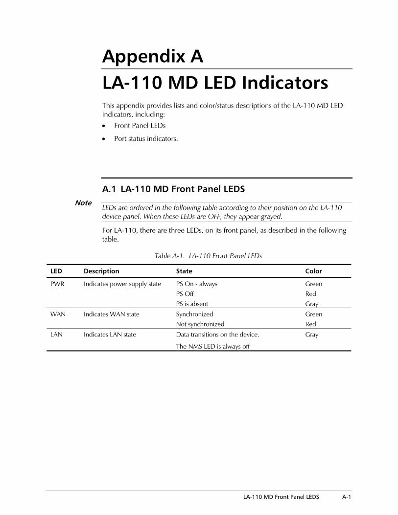
LA-110 MD Front Panel LEDS A-1
Appendix A LA-110 MD LED Indicators This appendix provides lists and color/status descriptions of the LA-110 MD LED indicators, including:
• Front Panel LEDs
• Port status indicators.
A.1 LA-110 MD Front Panel LEDS •
LEDs are ordered in the following table according to their position on the LA-110 device panel. When these LEDs are OFF, they appear grayed.
For LA-110, there are three LEDs, on its front panel, as described in the following table.
Table A-1. LA-110 Front Panel LEDs
LED Description State Color
PWR Indicates power supply state PS On - always PS Off PS is absent
Green Red Gray
WAN Indicates WAN state Synchronized Not synchronized
Green Red
LAN Indicates LAN state Data transitions on the device.
The NMS LED is always off
Gray
Note

Appendix A LA-110 MD LED Indicators 5620 Model Descriptor for LA-110 User’s Manual
A-2 LA-110 MD Module and Port Status
A.2 LA-110 MD Module and Port Status
Operational status for each physical module and port is indicated by the frame color of the module (as shown in the 5620 Shelf View) and port itself (as shown in the LA-110 Draw), based both on polling and notifications of interfaces operational status.
When the frame color of the port is:
• Red: it indicates that the operational status is down. (There are failures on the port.)
• Green (Gray in 5620): it indicates that the operational status is up (ready to pass packets). The port is OK and no tests are running on it.
• Purple: it indicates that the operational status is unknown, and/or a loopback test.

I-1
Index
—A— AAL1
selection, 3-15
AAL1 Stream application mode, 4-13
interface statistics, 4-58 AAL1 Stream paths
configuring, 6-23 alarms
clearing history log, 3-24
history, 3-22
indication, 2-9
viewing, 3-21 architecture
5620 network management, 1-2 ATm to FR IWF settings, 3-16
—C— CES E1 port
bundles configuration, 4-52
bundles table, 4-54
configuration, 4-48
interface information, 4-51
loopback testing, 4-55
monitoring, 4-81
parmeters, 4-49 CES path parameters
viewing and modifying, 6-12 configuration
CES E1 port, 4-48
LAN port, 4-19
port, 4-1, 4-4
resetting, 3-25
restoring default, 3-25
SHDSL port, 4-35 Configuration tool, 2-12 cross connection, 5-1
AAL1 Stream VC, 5-7, 5-26
adding, 5-1
CES VC, 5-3, 5-15
configuring, 5-9
deleting, 5-32
FR VC, 5-6, 5-22
LAN VC, 5-1, 5-9
performance monitoring, 5-30
—D— Data FR
configuring, 6-23 Data FR port
application mode, 4-6 Data port
application, 4-5
monitoring, 4-57 descriptor
settings, 3-19 Descriptor Module
5620 SNMP, 1-1 Drawing Tool, 2-10
—F— FR interface
statistics, 4-57
—G— graphical user interface
using, 2-8
—H— hardware
requirements, 2-1
resetting device, 3-25 history log
clearing, 3-24 host interface
parameters, 3-6
—I— installation
5620 SNMP DM, 2-1
—L— LA-110
overview, 1-2 LA-110 node
creating, 2-4
deleting, 2-7

Index 5620 Model Descriptor for LA-110 User's Manual
I-2
LA-110 ports displaying, 2-7
LAN interface statistics, 4-60
LAN port configuration, 4-19
monitoring, 4-59 LEDs
front panel, A-1
LA-110 MD, A-1 links
configuring and monitoring, 6-1
deleting, 6-21
information, 6-20
SHDSL, 6-1
viewing, 6-20
—M— Manager List, 3-11 module
status color indicators, A-2 Monitor tool, 2-12 monitoring
performance, 4-56
—N— Navigator tool, 2-11
—P— path management, 6-1 paths
ATM VCC, 6-6, 6-15
CES, 6-12
configuring and monitoring, 6-1
deleting, 6-21
Ethernet, 6-6
LAN to LAN, 6-6
viewing, 6-20 performance
monitoring, 4-56 port
CES E1, 4-48, 4-81
configuration, 4-1, 4-4
Data AAL1 Stream, 4-57
Data FR, 4-6, 4-57
Data FR application, 4-5
LAN, 4-19, 4-59
operations, 4-3
parameters, 4-3
selecting, 4-1
SHDSL, 4-35, 4-62
SHDSL AAL1 statistics, 4-74
SHDSL AAL5 statistics, 4-77
SHDSL ATM layer statistics, 4-68
SHDSL ATM layer VCL statistics, 4-72
SHDSL physical layer statistics, 4-62
status color indicators, A-2
—R— Rediscover tool, 2-12
—S— SHDSL port
AAL1 statistics, 4-74
AAL5 statistics, 4-77
ATM layer statistics, 4-68
ATM layer VCL statistics, 4-72
configuration, 4-35
monitoring, 4-62
physical layer statistics, 4-62 SNMP 5620 Descriptor Module, 1-1 SNMP community, 3-18 statistics
AAL1 Stream interface, 4-58
FR interface, 4-57
LAN interface, 4-60 status bar, 2-12 system
faults, 3-21
information, 3-3
log buffer, alarms history, 3-22
parameters, 3-5
preferences, 3-20
resetting configuration, 3-25
resetting hardware, 3-25
resetting statistics, 3-26
restoring default configuration, 3-25
selecting, 3-1
viewing and modifying configuration, 3-3
viewing online help, 3-26
—T— tool
Configuration, 2-12
Monitor, 2-12
Navigator, 2-11
Rediscover, 2-12 Traffic Descriptor settings, 3-8

24 Raoul Wallenberg St., Tel Aviv 69719, IsraelTel: +972-3-6458181, Fax: +972-3-6483331, +972-3-6498250E-mail: , Web site:
Customer Response Form RAD Data Communications would like your help in improving its product documentation. Please complete and return this form by mail or by fax or send us an e-mail with your comments. Thank you for your assistance!
Manual Name: _ __________________________________
Publication Numb
Please grade the
Installation instruc
Operating instruc
Manual organizati
Illustrations
The manual as a w
What did you like______________ ______________ ______________ ______________ ______________
[email protected] www.rad.com
5
___________________________620 Model Descriptor for LA-110er: _ _______________________________________________
man
tions
tions
on
hole
abo____
____
____
____
____
3 5
__________99-200-05/0ual according to the following factors:
Excellent Good Fair Poor Very Poor
❒ ❒ ❒ ❒ ❒ ❒ ❒ ❒ ❒ ❒ ❒ ❒ ❒ ❒ ❒ ❒ ❒ ❒ ❒ ❒
❒ ❒ ❒ ❒ ❒
ut the manual? _________________________________________________________
_________________________________________________________
_________________________________________________________
_________________________________________________________
_________________________________________________________


Error Report Type of Error(s) ❒ Incompatibility with product
or Problem(s): ❒ Difficulty in understanding text
❒ Regulatory information (Safety, Compliance, Warnings, etc.)
❒ Difficulty in finding needed information
❒ Missing information
❒ Illogical flow of information
❒ Style (spelling, grammar, references, etc.)
❒ Appearance
❒ Other _________
Please list the exact page numbers with the error(s), detail the errors you found (information missing, unclear or inadequately explained, etc.) and attach the page to your fax, if necessary. _________________________________________________________________________________________
_________________________________________________________________________________________
_________________________________________________________________________________________
_________________________________________________________________________________________
Please add any comments or suggestions you may have. _________________________________________________________________________________________
_________________________________________________________________________________________
_________________________________________________________________________________________
You are: ❒ Distributor
❒ End user
❒ VAR
❒ Other ________________________
Who is your distributor? _______________________________
Your name and company: ___________________________________________________________
Job title: __________________________________________________________________________
Address: __________________________________________________________________________
Direct telephone number and extension: _______________________________________________
Fax number: ______________________________________________________________________
E-mail: _____________________________________________________________________


900 Corporate Drive, Mahwah, N.J. 07430, Tel: (201) 529-1100
24 Raoul Wallenberg Street, Tel Aviv 69719, Israel, Tel: 972-3-6458181
U.S. HEADQUARTERS:
INTERNATIONAL HEADQUARTERS:
Publication No. 399-200-05/05
www.rad.com
Fax: 972-3-6498250, 972-3-6474436, Email: [email protected]
Toll Free: 1-800-444-7234, Fax: (201) 529-5777, Email: [email protected]