
Model Based Testing: An Evaluation - DiVA portal831658/FULLTEXT01.pdf · Model Based Testing: An...
89
MEE10:30 Model Based Testing: An Evaluation Yasir Masood Malik This thesis is presented as part of Degree of Master of Science in Electrical Engineering Blekinge Institute of Technology May 2010 Blekinge Institute of Technology R&D Services School of Engineering Tools & Test Centre, Karlstad Department of Electrical Engineering Tieto Sweden AB Supervisor: Prof. Hans-Jurgen Zepernick Supervisors: Robert Magnusson Examiner: Prof. Hans-Jurgen Zepernick & Sören Torstensson
-
Upload
nguyenminh -
Category
Documents
-
view
221 -
download
0
Transcript of Model Based Testing: An Evaluation - DiVA portal831658/FULLTEXT01.pdf · Model Based Testing: An...

MEE10:30
Model Based Testing: An
Evaluation
Yasir Masood Malik
This thesis is presented as part of Degree of
Master of Science in Electrical Engineering
Blekinge Institute of Technology
May 2010
Blekinge Institute of Technology R&D Services
School of Engineering Tools & Test Centre, Karlstad
Department of Electrical Engineering Tieto Sweden AB
Supervisor: Prof. Hans-Jurgen Zepernick Supervisors: Robert Magnusson
Examiner: Prof. Hans-Jurgen Zepernick & Sören Torstensson

ii

iii
Abstract:
In today’s telecommunication market, the increased complexity in the system and
short release cycle of a product is becoming a challenge for the product testers. Due to
increased competition in the telecom sector, a high reliability of complex software is always
demanded by the customer, along with the cost reduction, from his contractor. A product has
to be tested again if a small modification or some extra functionality is added in it. As testing
is traditionally performed manually, which cannot assure that the software is tested using all
possible combination of inputs. Therefore, to enhance the reliability of tests, there is a need of
techniques which can improve the manual way of testing and assure the high performance and
evaluation of the product.
Clearly, the test automation techniques are getting more consideration due to its
benefits. Therefore, in this thesis work an evaluation is made on model based testing (MBT)
using Qtronic by Conformiq. Qtronic is a tool for automatic test case design that is driven by
‘design models’. A simplified automatic teller machine (ATM) client-server system is used
initially as a system under test (SUT), which is implemented in Java. Qtronic modeling
language (QML) is used to design a model of ATM using finite state machines (FSM)
notation. The ‘design model’ is a description of the intended behavior of the system on some
level of abstraction. Qtronic designs test cases for a system automatically when it is given a
‘design model’ of a system as an input.
The complexity of the test object is increased incrementally to evaluate how well
suited Qtronic is for incremental design and how changes in a test object affects model based
testing in broad implementation. Furthermore, an experiment is also performed to evaluate the
test generation time of Qtronic, by moving the ‘core logic’ of the model to the test harness.
However, it is recommended that a larger and more complex test object should be used to
evaluate the model based testing using Qtronic.

iv

v
Acknowledgement I would like to express my deepest sense of gratitude to my GOD, Almighty Allah
who gave me strength and courage to complete this gigantic task.
I would like to thanks my supervisors, Robert Magnusson and Sören Torstensson, for
giving me an opportunity to work on this interesting project. Their throughout support, useful
guidance, encouragement and timely assistance helped me to complete this thesis work on
time. I must thank to Prof. Hans-Jurgen Zepernick, whose worthy comments made this report
more pleasant.
Thanks to my friends Johan, Ahmer, Fakhar and Mahboob for their moral support
during the thesis work.
I must express my gratitude to my parents, for their continuous support and
encouragement.

vi

vii
Contents
1 Introduction 1
1.1 Problem statement 1
1.2 Scope of the Thesis 1
1.3 Division of Thesis Work 2
1.4 Outline of Thesis 2
2 Background 3
2.1 Software Testing 3
2.1.1 Different Kinds of Testing 4
2.2 Model Based Testing 7
2.2.1 What is Model Based Testing? 7
2.2.2 Model Based Testing Process 9
2.2.3 Benefits of Model Based Testing 11
2.2.4 Disadvantages of Model Based Testing 13
3 Constructing the Test Object 15
3.1 Pre-study of the Pilot 15
3.2 Developing a frmaework for FSM 20
3.3 Pilot of PMc (First Version) 22
3.4 PMc with added functionality (Second Version) 24
3.5 PMc with internal modification (Third Version) 25
3.6 Summary 27
4 Conformiq Qtronic: An Automated Test Design Tool 28
4.1 Qtronic Modelling Language (QML) 28
4.2 Qtronic 30
5 Experiments 35
5.1 Experiment 1 36
5.1.1 Goals 36
5.1.2 Modelling of Version A 36
5.1.3 Settings for Test Case Generation 41
5.1.4 Implementation of Test Harness and Test Execution Environment 42
5.2 Experiment 2 44
5.2.1 Goals 44
5.2.2 Modelling of Version B 44
5.2.3 Settings for Test Case Generation 47
5.2.4 Implementation of Test Harness and Test Execution Environment 47
5.3 Experiment 3 49
5.3.1 Goals 50
viii
5.3.2 Modelling of Version C 50
5.3.3 Settings for Test Case Generation 53
5.3.4 Implementation of Test Harness and Test Execution Environment 54
5.4 Experiment 4 54
5.4.1 Goals 55
5.4.2 Modelling of Version D 55
5.4.3 Settings for Test Case Generation 56
5.4.4 Implementation of Test Harness and Test Execution Environment 57
5.5 Summary 58
6 Results and Analysis 59
6.1 Experiment 1 59
6.1.1 Results 59
6.1.2 Analysis 61
6.2 Experiment 2 64
6.2.1 Results 64
6.2.2 Analysis 65
6.3 Experiment 3 67
6.3.1 Results 67
6.3.2 Analysis 67
6.4 Experiment 4 69
6.4.1 Results 69
6.4.2 Analysis 69
6.5 Summary 70
7 Conclusion and Future Work 72
7.1 Conclusion 72
7.2 Future Work 73
8 Reference 74
9 Appendix 76
ix
List of Figures
Fig. 2.1: Different Kinds of Testing
Fig. 2.2: Model Based Testing in Testing Process
Fig. 2.3: Model Based Testing Process
Fig. 3.1: Overview of Subsystem and Interfaces of an ATM and a Bank Computer
Fig. 3.2: MSC of establishing connection between PMc and PMs via TSP
Fig. 3.3: MSC of successful cash withdrawal from ATM
Fig. 3.4: Framework of FSM using behavioural design pattern
Fig. 3.5: State transition diagram for a pilot PMc of ATM
Fig. 3.6: Implementation of a PMc on the frmaework of FSM
Fig. 3.7: A state transition diagram of Biometric Authentication
Fig. 4.1: An Example Model in QML Modeller
Fig. 4.2: QML textual notation for exemplified model.
Fig. 4.3: Overview of the coverage editor
Fig. 4.4: Test generation status in Eclipse console window
Fig. 4.5: Test Case list
Fig. 4.6: Traceability matrix view
Fig. 4.7: Test Step View
Fig. 4.8: MSC of TestCase3
Fig. 5.1: The Hierarchy of MBT applied on test objects
Fig. 5.2: Overview of Version A
Fig. 5.3: External ports defined in QML textual notation
Fig. 5.4: Record definition for PMc in QML textual notation.
Fig. 5.5: Illustration of External Port used for Expected Event.
Fig. 5.6: Function Definition in QML textual notation.
Fig. 5.7: Reusing a Record in QML.
Fig. 5.8: illustration of Error Handling in PMc Model.
Fig. 5.9: Testing goals for Version A.
Fig. 5.10: Test Cases generation from the model of Version A in a test suite
Fig. 5.11: Procedure definition in TCL format.
Fig. 5.12: Overview of the Test Execution Environment.
Fig. 5.13: Overview of Version B.
Fig. 5.14: Definition of one of the modified record in QML textual notation.
Fig. 5.15: Illustration of parameter handling in QML.
Fig. 5.16: One of the procedures definition in QML textual notation.
Fig. 5.17: Few lines of code of Testcase37 in TCL format.
Fig. 5.18: Two of the modified procedure in test harness.
Fig. 5.19: Illustration of Instantiating Biometric Authentication in PMc model
Fig. 5.20: Function definition of Biometric Authentication in QML textual notation.
Fig. 5.21: The model of Biometric Authentication state machine in QML.
Fig. 5.22: Definition of internal ports in QML textual notation.
Fig. 5.23: The two procedures added in Test Harness for Biometric Authentication.
Fig. 5.24: Modified record definition for Version D in QML textual notation.
Fig. 5.25: Modified function sendTData for Version D in QML textual notation.
Fig. 5.26: Illustration of transmitting data packet without a payload.
Fig. 5.27: Two of the Procedures modified in the Test Harness of Version D.
x
List of Tables
Table 2.1: Time Spent to fix the bug in different stages
Table 3.1: Primitives for SPIc and SPIs over TSP
Table 3.2: Primitives for the Service User Interface, Client side (SUIc)
Table 3.3: Headers for the protocol interface (PTI)
Table 3.4: Primitives for the Service User Interface, Server side (SUIs)
Table 3.5: Additional Service Primitives for the SUIc
Table 3.6: Additional Headers for the protocol interface (PTI)
Table 3.7: Service Primitives for the SUIc in Biometric Authentication
Table 3.8: Biometric Authentication Headers for the protocol interface (PTI)
Table 5.1: Substitute names for the different PMc
Table 5.2: External Ports defined in Version A for PMc
Table 6.1: Results of Experiment 1
Table 6.2: Results of Experiment 2
Table 6.3: Example for Boundary Value Analysis
Table 6.4: Results of Experiment 3
Table 6.5: Results of Experiment 4

1
1. Introduction
In today’s telecommunication market, the increased complexity in the system and
short release cycle of a product is becoming a challenge for the product testers. Usually the
testing part of a product comes quite late in the release process, which makes the product
testers under severe pressure. Due to increased competition in the telecom sector, a high
reliability of complex software is always demanded by the customer, along with the cost
reduction, from his contractor. A product has to be tested again if a small modification or
some extra functionality is added in it. Testing is traditionally performed manually, which
cannot assure that the software is tested using all possible combination of inputs. To enhance
the reliability of tests, there is a need of techniques which can improve the manual way of
testing and assure the high performance and evaluation of the product.
Tieto R&D Services is a company, operating in different countries. It mainly provides
solutions to most of the world wide companies. The company is also working in
software/hardware testing areas using traditionally testing techniques. As the test automation
techniques is getting more into consideration due to its benefits, described in Section 2.2,
Tieto R&D Services wants to evaluate the model based testing technique, in order to use this
technique in future. Thus, an evaluation is made on model based testing in this thesis work.
1.1 Problem Statement
The thesis work aims to develop a model for a system using finite state machine with
gradually increased complexity. A tool with support for model based testing shall be used to
generate the test cases. The main questions for this thesis were:
a) What logic should be implemented as a test object using finite state machine?
b) How to create an adapter between the test object and test scripts to execute the test
cases?
1.2 Scope of the Thesis
The hypothesis drawn from the questions raised above could be:
a) To develop a framework for a finite state machine and implementing a simple logic on
the framework in the beginning (with incrementally higher complexity). And that
framework could be used as a test object in this thesis work, which can be
implemented in Java or C++.
b) To establish a test environment including the development of a test harness between
the test object and test cases/scripts.
2
1.3 Division of Thesis Work
This thesis work is done by two students, me and Johan Nordholm. As we both are
from different universities, therefore we wrote our thesis reports individually. However, the
experiments in this thesis work are performed by both of us together. Thus, only the
specifications of the test system and its results are used by both of us in our thesis report.
1.4 Outline of the Thesis
The thesis report is divided into seven chapters. The first chapter is the introduction, in
which a statement of problem and the hypothesis is discussed. The second chapter is about the
background, which is about software testing and model based testing. In the third chapter, the
construction of system under test (SUT, i.e. test object) is described in detail. The fourth
chapter contains the information about Qtronic by Conformiq (the MBT tool used in this
thesis work). In chapter five, a detailed description of all the experiments performed in this
thesis work is described. The results and analysis for all experiments are discussed in chapter
six. Finally, chapter eight is about conclusion and the future work.
3
2. Background
In this chapter, software testing is discussed initially, in which a brief description of its
key factors will be described. Subsequently to software testing, the model based testing
technique used in this thesis work is described.
2.1 Software Testing
Software testing is any activity aimed at evaluating an attribute or capability of a
program or system and determining that it meets its required results [9]. Although it is
essential for the software quality and widely deployed by programmers and testers, software
testing still remains an art due to limited understanding of the principles of software. As the
complexity of the software increases, it becomes very difficult to test it completely. The
purpose of testing can be quality assurance, reliability estimation, or verification and
validation of the software. Software testing is basically a trade-off between time, budget, and
quality.
To assure this quality, reliability, or verification and validation, it is necessary to
eliminate the possibility of bugs in the software design. The minimum requirement of quality
means that software is performing as required under specified circumstances. Software bugs
almost exist in every software unit, mostly in the complex systems. Although it is not a
programmers fault or his incompetence while designing the software modules, but the
limitation of human ability to manage complex systems, hence some design defects remain in
the software. However, discovering these design defects in software is also a challenging task,
for the same reason of complexity.
One of the complications usually arises when the dynamic nature of software are being
tested. In this case, if a failure occurs during preliminary testing and the code is modified to
get the desired output, the software may now work for a test case that did not work
previously. However, its behaviour on pre-error test cases, which it passed before, can no
longer be guaranteed. Thus testing should be restarted, in order to evaluate the software again.
However, the expense of doing this is often prohibitive [19].
Software testing can be costly in some cases, but it could be more expensive if the
software is not tested. For instance airplane crash, halted trading on the stock exchange, failed
space shuttle launch etc. can really cause disasters. As described earlier that testing is a trade-
off between budget, time and quality. In software testing, most often used approach is to stop
testing whenever some or any of the allocated resources, i.e. time, budget, or test cases are
4
exhausted. The optimistic stopping rule is to stop testing when either reliability meets the
requirement, or the benefit from continuing testing cannot justify the testing cost [17]. This
will usually require the use of reliability models to evaluate and predict reliability of the SUT.
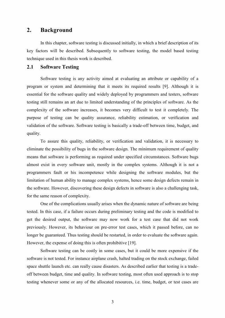
It is commonly believed that the earlier a defect is found, the cheaper it is to fix it [10].
For instance, if a problem in the requirements is found in post-release, then it would cost 10–
100 times more to fix it than if it had already been found by the requirements review. Table
2.1 shows the cost of fixing the defect depending on the stage it was found.
Table 2.1: Time spent to fix the bug in different stages [13].
Time Detected
Requirement Architecture Construction System
Test
Post
Release
Requirement 1x 3x 5-10x 10x 10-100x
Architecture - 1x 10x 15x 25-100x
Time
Introduced
Construction - - 1x 10x 10-25x
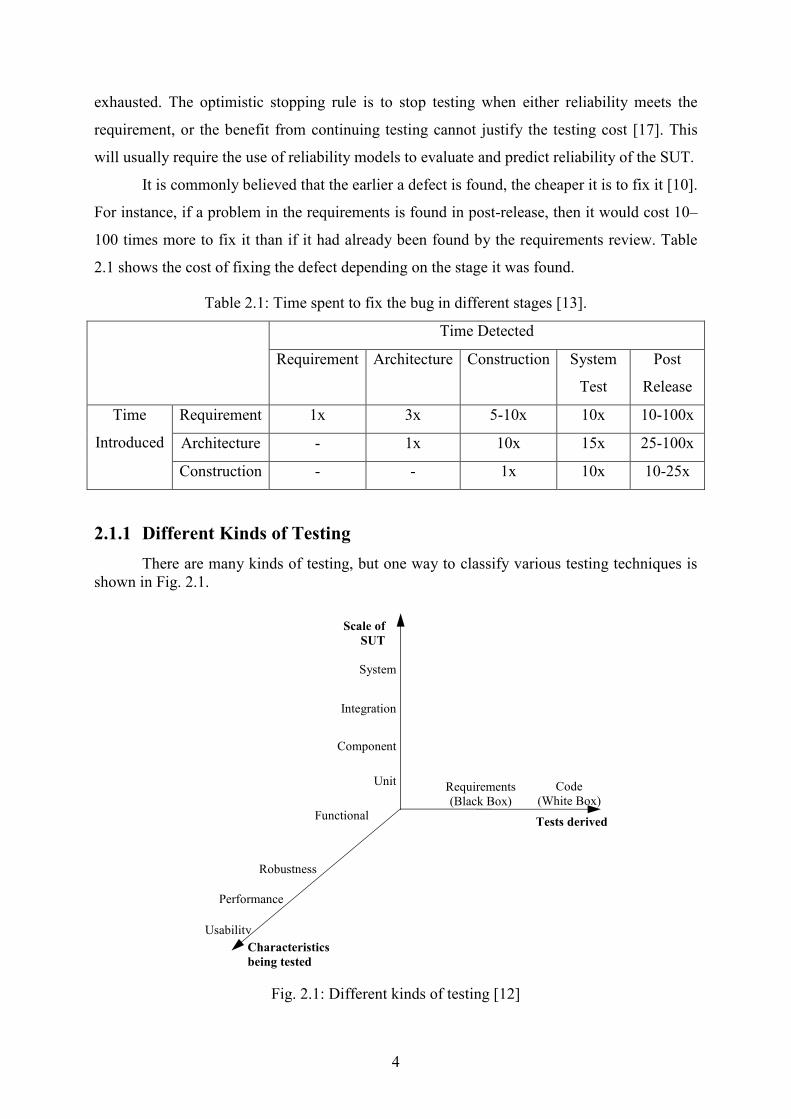
2.1.1 Different Kinds of Testing
There are many kinds of testing, but one way to classify various testing techniques is
shown in Fig. 2.1.
Fig. 2.1: Different kinds of testing [12]
Component
Unit
Integration
System
Scale of
SUT
Functional
Robustness
Performance
Usability
Requirements
(Black Box)
Code
(White Box)
Characteristics
being tested
Tests derived
5
These different kinds of testing are defined in three dimensions. One dimension is
showing the scale of SUT, which ranges from a small unit up to whole system. The second
dimension shows the different characteristics that we may want to test. The third dimension
shows the kind of information, we may want to use during software testing.
Before describing these different kinds of testing, some basic terms of standard IEEE
software engineering terminology is reviewed in brief.
A failure is an undesired behaviour. Failures are typically observed during the
execution of the system being tested.
A fault is the cause of the failure. It is an error in the software, usually caused by
human error in the specification, design, or coding process. It is the execution of the
faults in the software that cause failures. Once we have observed a failure, we can
investigate a failure to find the fault that caused it and correct that fault.
Therefore, testing is the activity of executing a system in order to detect failures. It is
different from, and complementary to, other quality improvement techniques such as
static verification, inspections, and reviews. It is also distinct from the debugging and
error-correction process that happens after testing has detected a failure.
Various kinds of testing, shown in Fig. 2.1, are described below.
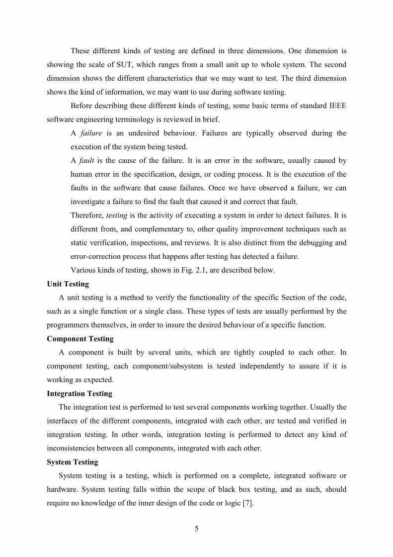
Unit Testing
A unit testing is a method to verify the functionality of the specific Section of the code,
such as a single function or a single class. These types of tests are usually performed by the
programmers themselves, in order to insure the desired behaviour of a specific function.
Component Testing
A component is built by several units, which are tightly coupled to each other. In
component testing, each component/subsystem is tested independently to assure if it is
working as expected.
Integration Testing
The integration test is performed to test several components working together. Usually the
interfaces of the different components, integrated with each other, are tested and verified in
integration testing. In other words, integration testing is performed to detect any kind of
inconsistencies between all components, integrated with each other.
System Testing
System testing is a testing, which is performed on a complete, integrated software or
hardware. System testing falls within the scope of black box testing, and as such, should
require no knowledge of the inner design of the code or logic [7].

6
Functional Testing
Functional testing is one of the most common testing types, which verifies that the system
behaves correctly and works at least to some of the requirements, models or any other design
paradigm used to specify the application. Functional testing is also known as behavioural
testing, which aims to detect errors in the functionality of the system.
Robustness Testing
Robustness testing is used to detect the errors in the system under invalid conditions. For
instance, by applying unexpected inputs, or test the system without its dependent applications.
Usually a system is said to be robust if it does not hang or crash during its testing.
Performance Testing
Performance test is done on a system, in order to test its throughput under heavy load. The
goal of this test is to determine, if the system does not crash in conditions of insufficient
computational resources.
Usability Testing
In usability testing, a product is evaluated by finding user interface problems, which may
make the software difficult to use or user might misinterpret the software’s output. Also more
soft values like easy to use and look and feel of product can be tested in this test phase. This
can be seen as an irreplaceable usability practice, since it gives direct input on how real users
use the system [14].
Black Box Testing
In black box testing, a SUT is treated as Black Box, which means that we do not have any
knowledge about the internal structure of the system. In black box testing, the tests are
designed from the system requirements, which describe the expected external behaviour of the
system. Therefore, black box testing has the advantage of "an unaffiliated opinion", on the
one hand, and the disadvantage of "blind exploring," on the other [16].
White Box Testing
In white box testing, the tests are designed using the implementation code of the system.
For instance, a set of tests could be designed to ensure the coverage of every statement or a
function in the code. Hence, each statement or function will be executed by every test case.
White box testing methods can also be used to evaluate the completeness of a test suite that
was created with black box testing methods. This allows the software team to examine parts
of a system that are rarely tested and ensures that the most important function points have
been tested [18].
7
2.2 Model Based Testing
In this chapter, model based technique will be described in detail. Firstly, model based
technique will be defined, which will be followed by the processed involved in model based
testing. The pros and cons of model based testing will be described later in this chapter.
2.2.1 What is Model Based Testing?
Model based testing is the automatic generation of efficient test cases, using models of
system requirements and specified functionality. By applying model based testing, defects can
be found earlier in the development process compared to the use of manual testing practices
[11]. Model based testing offers many advantages, such as a high degree of automation,
ability to generate high volumes of non-repetitive useful tests, means to evaluate regression
test suites and the possibility of estimating a number of statistical measures of software
quality [5]. Therefore, scope of model based testing is shown in Fig. 2.2.
Fig. 2.2: MBT in testing process.
As model based technique is usually used for black box testing, therefore the scope of
model based testing includes only the requirements of system model (see Fig. 2.2). The main
use of model based testing is to generate functional testing, which covers the complete scale
Component
Unit
Integration
System
Scale of SUT
Functional
Robustness
Performance
Usability
Requirements
(Black Box)
Code
(White Box)
Characteristics
being tested
Tests derived
Model
Based
Testing

8
of SUT (see Fig. 2.2). However, model based technique can also be used for robustness
testing, in which invalid inputs can be given to the SUT. It is not yet widely used for
performance testing, but this is an area under development [12].
The following are the four main approaches known as model based testing, described
by Mark Utting and Bruno Legeard [12]:
1. Generation of test input data from a domain model.
2. Generation of test cases from an environment model.
3. Generation of test cases with oracles from a behaviour model.
4. Generation of test scripts from abstract tests.
In the first approach, the model provides the information about the domain of the input
values. The test generation involves clever selection and combinations of a subset of those
values to produce test input data. This approach is obviously of great practical importance, but
it does not solve the complete test design problem because it cannot provide any information,
that either the test case passed or failed.
The second approach uses a model to describe the expected environment of the SUT.
From these environments, sequence calls can be generated from this model, but generated
sequence calls do not specify the expected output of the SUT. The environment model does
not model the behaviour of the SUT, meaning that it is not possible to predict the output
values. In other words, it is difficult to determine accurately, that either a given test passed or
failed.
The third meaning of model based testing is the generation of executable test cases
which include oracle information or some automated check on the actual output values to see
if they are correct. Oracle information is input values associated with operations and the
corresponding expected output values. This is a more challenging task than the two previously
mentioned approaches. The test generator must know enough about the expected behaviour of
the SUT, such as the relationship between input and output, in order to generate test cases
with oracles. Hence, the model must describe the expected behaviour of the SUT. Thus, this is
one of the four approaches, described in this Section, which addresses the whole test design
problem from choosing input values and generating sequence calls to generate executable test
cases that include verdict information.
The final approach assumes an abstract description of a test case, such as a UML
sequence diagram, and focuses on transforming that abstract test case into a low-level test
script that is executable. The model is the information about the structure and API of the SUT,
and the details of how to transform a high-level call into executable test scripts.

9
2.2.2 Model Based Testing Process
Model based testing can be defined as the automation of the design of black box tests
[12]. The difference from the usually used black box testing is that rather using manually
writing tests, which are based on requirement documentation, a model is created instead,
which behaves as an expected SUT. A general process of model based testing is shown in Fig.
2.3.
Fig. 2.3: MBT Process [12].
The model is based on the system requirements. Then the model based testing tools
are used to automatically generate test cases using these models. That leads us to two
questions [12]:
1. What is a model?
2. What notation should we used to write models?
The two illumination definitions of the word model, from the American Heritage
Dictionary are as follows [12]:
Requirements
Model
Test Case
Generator
Test Cases
Test Script
Generator
Test Scripts
Adaptor
Test Execution Tool
System
under Test
Requirements
Traceability
matrix
Model Coverage
1: Model
2: Generate
3: Concretize
4:Execute
5: Analyze
Test Results
Test Plan

10
1. A small object, usually built to scale, that’s represents in detail another, often large
object.
2. A schematic description of a system, theory, or phenomenon that accounts for its
known or inferred properties and may be used for further study of its characteristics.
These definitions show the two most important characteristics of a model, we might
use in model based testing. Firstly, the model should be small as compare to the SUT, so that
the testing does not cost too much. Secondly, the model should be detailed enough, that it
should behave exactly as the system which we want to test.
Model based testing automates the detailed design of test cases and the generation of
the traceability matrix. Instead of writing hundreds of test cases, the test designer creates an
abstract model of the system under test. The model based testing tool is then used to generate
a set of test cases from that model, which eventually gives the advantage of reduced design
time. A variety of test suites can also be generated from the same model simply by using
different test selection criteria [12].
The process of model based testing can be divided into five main steps [12]:
1. Model the SUT and/or its environment.
2. Generate abstract tests from the model.
3. Concretize the abstract tests to make them executable.
4. Execute the tests on the SUT and assign verdicts.
5. Analyze the test results.
The first step of model based testing is to construct an abstract model, which could be
really a simplified, behavioural model of the system being tested. It should not be very
detailed, but it should focus on the key aspects to be tested and be based on the specified
requirements [12].
After creating the behavioural model of the system the next step is to generate abstract
test cases from that model. Hence to generate the test cases, a test selection criterion needs to
be specified, since the number of possible tests may be infinite. For example, interaction with
the test generation tool might be necessary to focus on a particular part of the model or to
choose a particular model coverage criterion, such as to cover all transitions or cover all states
in a finite state machine [12].
Since the model is an abstraction of the SUT, therefore the abstract test cases cannot
be executed directly. A requirement traceability matrix, which links functional requirements

11
with test cases to determine which requirements are covered by an individual test case, or
various coverage reports are additional outputs of this step for most model based testing tools.
Coverage reports indicate how well the test cases cover the behaviour of the model, while a
requirement traceability matrix traces the link between functional requirements and generated
test cases [12].
When the abstract test cases are generated they need to be transformed into executable
concrete tests. This may be done by some separate transformation tool or it could be done by
writing some adaptor code that implements each abstract operation to map against the lower-
level SUT interface. The aim of this step is to bridge the gap between abstract test cases with
the concrete SUT by adding details not included in the abstract model [12].
This two-layer approach, i.e. abstract tests and concrete test scripts, has the advantage
of being independent of the language used to write tests and of the test environment. Hence,
just by changing the adaptor code, the tests can be reused in different test execution
environments [12].
The executable test scripts are then executed against the SUT. Using online model
based testing, the tests will be executed as they are produced. In this case the model based
testing tool handles execution and recording of the results. With offline model based testing, a
set of concrete test scripts has been produced. Hence the existing test execution tools and
practices can be used [12].
Finally the test execution results are analyzed, and correct actions have to be taken in
order to fix the bugs. For each failed test it must be determined what caused the failure. It
might be due to a fault in the SUT or to a fault in the test case itself. In the latter case this
must be due to a fault in the adaptor code or in the behavioural model of the system. Hence,
feedback about the correctness of the model is given in the last step [12].
2.2.3 Benefits of Model Based Testing
In this Section, the benefits of model based testing will be discussed. The most
attracting benefit of model based testing is that it automatically generates interesting cases
from the system model. The other major benefits, due to which one can use model based
testing technique are: SUT fault detection, reduced testing time and cost, improved test
quality, requirement defect detection, traceability and requirement evolution.

12
SUT fault detection
The aim of model based testing is the exposure of the failures in the SUT, which usually
caused by exhaustive combinations of inputs, memory leakage, and sometime failures occur
due to exercising different combinations of variables [5].
Comparative studies [4] [15] [3] [1] show that model based testing works better at fault
detection than manually designed tests. However, its fault detection power depends on the
skill and experience of those writing the model and choosing the test selection criteria [12].
Reduced testing time and cost
Model based testing practices will lead to less time and effort spent on testing in case of
time needed to write and maintain the model, as well as the time spent on directing the test
generation is less than the cost of manually designing and maintaining a test suite. It might
also save time during the failure analysis stage after test execution. Firstly, because failures
are reported in a consistent way and secondly, because some model based tools are capable of
finding to shortest possible test sequence that causes the failure. Thirdly, since not only the
code can be inspected, but also the abstracted test cases which give an overview over the test
sequence through the model [12].
Improved test quality
While performing manual testing, the quality of tests is highly dependent on the test
engineer and the test design process is usually not reproducible. Model based testing however
uses an automated test generator based on algorithms and heuristics to choose the test cases
from the model, which makes the design process systematic and repeatable. Since the input
data and the test oracles are generated from the model, the cost of generating more executable
test scripts is just the computing time required to generate them [12].
Model Coverage
The test progress and the generated test cases can be evaluated using coverage criterion,
defined before the test generation. Coverage can also be expressed for a model, therefore
model coverage is another heuristic that provides insight into the thoroughness and
effectiveness of the testing effort, especially when testing does not reveal failures. Coverage
typically deals with the control-flow through the model [12].

13
Requirements defect detection
Usually while writing the model for testing, it exposes issues in the informal requirements.
As in model based testing, the first step is to create an abstract model of the SUT, which
usually exposes requirements issues. This is a major benefit of model based testing because
requirements problems are a major source of system problems [12].
Traceability
Traceability is the ability to relate each test case to the model, to the test selection criteria,
and even to the informal system requirements. Traceability helps to explain the test case as
well as gives the justification for why it was generated. Moreover it can be used to optimize
test execution as the model evolves, since it enables the possibility to execute just the subset
of the tests that are affected by the model modifications. From an abstract view traceability is
a relation between the elements of the model and the test cases [12].
Requirements evolution
A considerable amount of efforts are often required to update the test suite as the
requirements of the system changes, while performing manual testing. However, in model
based testing only the model has to be updated and the tests can be regenerated. Since the
model is usually much smaller than the test suite, time is saved when updating the model
compared to updating all tests manually, resulting in faster response to evolving requirements
[12].
2.2.4 Disadvantages of Model Based Testing
Model based testing gives you a lot of benefits, which are described earlier, but there
are some limitations as well. A fundamental limitation of model based testing is that it cannot
guarantee to find all the differences between the model and the implementation, even if
generating a very large test set. However, this is a limitation for all kinds of testing [12].
Some of the limitations of model based testing are described below.
Outdated requirements
As software project evolves the informal requirements sometimes become out of date. If this
would apply when using model based testing, the wrong model will be built and test case
execution will yield a significant amount of errors in the SUT [12].

14
Useless metrics
In the manual test design process often a number of test cases designed are measures of
how the testing is progressing. Such measures are not useful when applying model based
testing, since the approach can generate huge numbers of test cases. Measurements of test
progress should instead move towards other measurements, such as SUT code coverage,
requirements coverage and model coverage metrics [12].
Inappropriate use of model based testing
In software testing, sometime it happens that some parts of the SUT may be difficult to
model and these parts could be tested manually. It’s not necessary that all areas of software
could be suitable for the use of model based testing. The risk is that it takes some experience
of model based testing usage to know which aspects of the SUT should be modelled and
which should be tested manually or by using other tools or techniques [12].
Tester skills
A practical limitation of model based testing is that some different skills are required
compared to manual test design. The model designers must the able to abstract and design the
models, in addition to being experts in the application area. This requires training costs and an
initial learning curve when starting to use model based testing [12].
State space explosion
Some drawbacks of model based testing cannot be avoided completely. For state models
the most prominent problem is state space explosion. Models of any non-trivial software
functionality can grow beyond manageable levels. Almost all other model based tasks, such as
model maintenance, checking and reviewing, non-random test generation and achieving
coverage criteria, are affected in this scenario [6].
Time to analyze failed tests
If any of the generated test fails, it must be decided whether the failure is caused by the
SUT, the adaptor code, or an error in the model. This is similar to manual testing, where it has
to be decided whether the failure was due to a fault in the SUT or in the test script. Model
based testing however generates test sequences that might be more complex and less intuitive
than manually designed test sequences. Thus, it might be more difficult and time-consuming
to find the cause of the failed test [12].
15
3. Constructing the Test Object
A complex test object can be used to determine the efficiency of the model based
testing in a good way. The approach adopted in this thesis work is to implement a simple test
object in the beginning, define requirements for it, and apply model based testing (MBT)
methodology on it.
After using MBT approach on a simple test object (pilot), the complexity of the test
object is increased incrementally and tested again using MBT technique. The complexity of
the test object is increased by first adding some features in the pilot, and then modifying the
updated pilot by introducing some extra functionality inside each feature. The incremental
versions of the test objects are described in this chapter in detail.
3.1 Pre-study of a Pilot
The pilot is a simple test object, which is developed as a framework for a finite state
machine (FSM). The logic implemented on the framework is a Protocol Module Client (PMc)
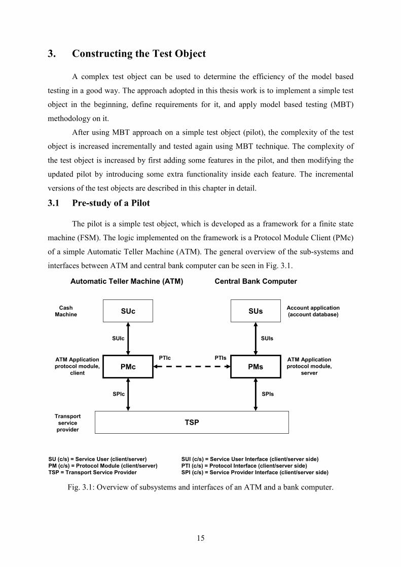
of a simple Automatic Teller Machine (ATM). The general overview of the sub-systems and
interfaces between ATM and central bank computer can be seen in Fig. 3.1.
PMc
Transport
service
provider
ATM Application
protocol module,
client
Automatic Teller Machine (ATM) Central Bank Computer
Cash
Machine
Account application
(account database)
ATM Application
protocol module,
server
TSP
SU (c/s) = Service User (client/server) SUI (c/s) = Service User Interface (client/server side)
PM (c/s) = Protocol Module (client/server) PTI (c/s) = Protocol Interface (client/server side)
TSP = Transport Service Provider SPI (c/s) = Service Provider Interface (client/server side)
SPIc
SUIsSUIc
SPIs
PTIsPTIc
PMs
SUc SUs
Fig. 3.1: Overview of subsystems and interfaces of an ATM and a bank computer.
16
The subsystems shown in Fig. 3.1 are interacting with each other using different
interfaces. The cash machine is basically a Service User Client (SUc), which interacts with
PMc using Service User Interface client (SUIc). The central bank is represented as a Service
User Server (SUs), which contains the database of user account information. The SUs
interacts with the PMs using Service User Interface server (SUIs).
The Protocol Module Client (PMc) and Protocol Module Server (PMs) are
communicating with each other through a Transport Service Provider (TSP). The Service
Provider Interface Client (SPIc) and Service Provider Interface Server (SPIs) are the
interfaces which are connecting the PMc and PMs to the TSP, respectively. The TSP is pure
OSI based transport service which is connection oriented, ensures reliable duplex data
transfer, packet oriented, and errors are signalled if a technical failure occurs. The two
interfaces, PTIc and PTIs, between PMc and PMs are only describing the logic interface.
For the interaction between PMc and PMs, there are some primitives, which are
defined for their communication over the TSP. These primitives are shown in Table 3.1.
Table 3.1: Primitives for SPIc and SPIs over TSP.
Service
primitive
Type Description
Req A T-service user initiates establishment of a reliable T-connection.
Ind Responding side receives request to establish a reliable T-
connection.
Resp+ Responding side grants the request.
Conf+ Initiating side get confirmation that the T-connection is established.
Resp- Responding side denies the request.
T-Connect
Conf- Initiating side get a negative confirmation. No T-connection could be
established. This may be caused by a T-Connect Resp- from the
responding T-service user or by problems within the T-service
provider.
Req A T-service user request sending of data to peer T-service user. T-Data
Ind A T-service user receives data from peer T-service user.
Req A T-service user requests that the T-connection is released. T-
Disconnect service is destructive so that any data sent that have not
been acknowledged may or may not have been delivered by the T-
service provider.
T-Disconnect
Ind The T-connection has been disconnected. This may be caused by a
T-Disconnect Req from the peer T-service user or by problems
within the T-service provider. If data cannot be delivered by the T-
service provider, then T-Disconnect Ind is the means to signal the
failure to the T-service user.
In Table 3.1, all three service primitives have a prefix T, which denotes the
transmission of data between PMc and PMs through the interfaces SUIc and SUIs over TSP.
17
The primitives T-Connect and T-Disconnect will be used to initiate the connection between
the PMc and PMs. When a user will insert an ATM card into an ATM, PMc will send a T-
Connect Request to the PMs using TSP. The PMs will receive a T-Connect Indication in
reaction to the PMc request, and it will either reply with a positive or negative response.
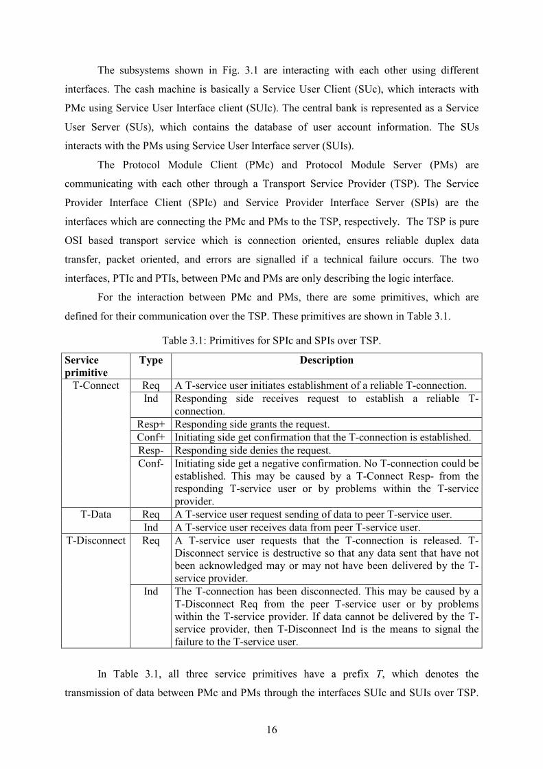
For the better understanding of the messages sent and received by PMc and PMs over
the TSP, a Message Sequence Chart (MSC) is drawn to explain the communication between
the two ATM modules. The general overview of a MSC, while establishing a connection
between PMc and PMs, is shown in Fig. 3.2.
SPIc TSP SPIs
T-Connect Req
PMc PMs
T-Connect Ind
T-Connect Resp+T-Connect Conf+
T-Data Req [data]T-Data Ind [data]
T-Data Req [data]T-Data Ind [data]
T-Data Req [data]T-Data Ind [data]
*
T-Disconnect ReqT-Disconnect Ind
Fig. 3.2: MSC of establishing connection between PMc and PMs via TSP.
After establishing a successful connection, both PMc and PMs will start sending and
receiving data to each other in order to perform different actions depending on the input from
the user via SUc. The primitive T-Data is responsible to carry the data packet from PMc to
PMs or vice versa. The T-Data could be of type Request or an Indication and will always
carry a header along with it. A header could be a command or acknowledgement from the
PMc or PMs, respectively.
The pilot ATM only allows two types of transactions at a time:
• Balance Query
• Withdraw Money

18
A user can make a Balance Query transaction to check the amount in the bank
account. A Balance Query transaction can be interrupted / cancelled by a user anytime in the
whole transaction. However, it’s not possible to Interrupt anytime while Withdraw Money
from ATM. Once the mechanism of Cash Dispense is started in Withdraw Money transaction,
the Interrupt key is disabled until the cash is dispensed from the ATM. There are some
primitives for SUIc which will be entered/displayed from/to the User on ATM screen. There
service primitives along with their description are listed in Table 3.2.
Table 3.2: Primitives for the Service User Interface client (SUIc).
Service
primitive
Direction Description: Actions of the ATM.
Card
inserted ↓ Bank identification and card number provided. Responded to by
Request PIN or Error message.
Request PIN ↑ Responded to by PIN input.
PIN input ↓ PIN code provided. Responded to Either by Request command or
Error message.
Request
command ↑ Responded to either by Balance query or Amount input (Withdraw
Money).
Balance
query ↓ Responded to either by Balance information or Error message.
Balance
information ↑ Not responded to. Balance information presented and card is
ejected.
Amount
input ↓ Responded to either by Dispense order or Error message.
Dispense
order ↑ If cash is available the cash is dispensed and Dispense result+ is
returned, else no cash is dispensed and Dispense result- is returned.
In both cases the card will be ejected.
Dispense
result + / - ↓ If Cash is available in Cash Machine, Dispense result+ will be
returned else Dispense Result-.
Error
message ↑ Not responded to. The error message is displayed due to the
Technical failure and the card will be ejected.
Interrupt ↓ Not responded to. The customer may interrupt at any time, up to
certain limits, after card is inserted. The card will be ejected.
The service primitives listed in Table 3.2 are the events and the actions between the
SUc and PMc via SUIc. The PMc will transfer these events, which are entered by the user, to
the PMs via TSP. As the user account information is stored in the SUs, so the PMs is
responsible to respond to these events eventually back to the PMc. The user information will
first be authenticated from SUs, and then the further process will be carried out either to make
a Balance Query or Withdraw Money.
In Table 3.2, the only downward arrow for Dispense Result +/- is an indication from
the PMc to the PMs, in order to respond the status of cash dispensed. Other then that, all the
19
downward direction of the arrows indicates the input from the user, and the upward arrows
indicate the response from the SUs to the SUc (User) on the ATM screen.
After an occurrence of an event to the PMc from the user, first the connection is
established between ATM and central bank, and then the transfer of data packets starts
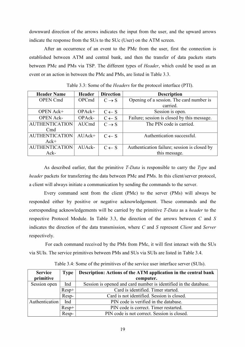
between PMc and PMs via TSP. The different types of Header, which could be used as an
event or an action in between the PMc and PMs, are listed in Table 3.3.
Table 3.3: Some of the Headers for the protocol interface (PTI).
Header Fame Header Direction Description
OPEN Cmd OPCmd C → S Opening of a session. The card number is
carried.
OPEN Ack+ OPAck+ C ← S Session is open.
OPEN Ack- OPAck- C ← S Failure; session is closed by this message.
AUTHENTICATION
Cmd
AUCmd C → S The PIN code is carried.
AUTHENTICATION
Ack+
AUAck+ C ← S Authentication successful.
AUTHENTICATION
Ack-
AUAck- C ← S Authentication failure; session is closed by
this message.
As described earlier, that the primitive T-Data is responsible to carry the Type and
header packets for transferring the data between PMc and PMs. In this client/server protocol,
a client will always initiate a communication by sending the commands to the server.
Every command sent from the client (PMc) to the server (PMs) will always be
responded either by positive or negative acknowledgement. These commands and the
corresponding acknowledgements will be carried by the primitive T-Data as a header to the
respective Protocol Module. In Table 3.3, the direction of the arrows between C and S
indicates the direction of the data transmission, where C and S represent Client and Server
respectively.
For each command received by the PMs from PMc, it will first interact with the SUs
via SUIs. The service primitives between PMs and SUs via SUIs are listed in Table 3.4.
Table 3.4: Some of the primitives of the service user interface server (SUIs).
Service
primitive
Type Description: Actions of the ATM application in the central bank
computer.
Ind Session is opened and card number is identified in the database.
Resp+ Card is identified. Timer started.
Session open
Resp- Card is not identified. Session is closed.
Ind PIN code is verified in the database.
Resp+ PIN code is correct. Timer restarted.
Authentication
Resp- PIN code is not correct. Session is closed.

20
The PMs will send commands to the SUs, which will be responded either by positive
or negative responses via SUIs. And on the basis of these responses from SUs, PMs will
acknowledge to the PMc either by positive or negative acknowledgement.
After defining the primitives for all the interfaces and possible interactions of the
subsystems with each other, a MSC is drawn for the understanding of message sequence
between PMc and PMs. The MSC for a successful cash withdrawal is shown in the Fig. 3.3.
OPAck+
AUCmd
AUAck+
OPCmdCard inserted
Request PIN
PIN input
Request Command
Amount input
Dispense order
Session open Ind
Session open Resp+
Authentication Ind
Authentication Resp+
Withdrawal prepare Ind
Withdrawal prepare Resp+
Witdrawal commit Ind
Witdrawal commit Resp+
WPCmd
WPAck+
WCCmd
WCAck+
Session close Ind
Dispense result+
SUc SUsPMsPMc SUIsSUIc PTI
CLCmdCLAck
Fig. 3.3: MSC of the successful cash withdraw from ATM.
The establishment of the connection between PMc and PMs is already shown in Fig.
3.2. Here in Fig. 3.3, a communication of the two protocol modules, PMc and PMs, after the
establishment of a connection is shown. The packets under the PTI are basically the Header,
which is carried by a T-Data primitive using TSP. The PTI is only a logical interface between
PMc and PMs. The actual data transmission, between PMc and PMs, will takes place using
TSP.
3.2 Developing a Framework for FSM
As described in the beginning of the chapter, a framework for a finite state machine
(FSM) will be developed first, and then the logic will be implemented on it. As the logic
implemented on the framework will be increased incrementally afterwards, so there is a need

21
to develop a framework which is reusable and flexible to modify if new requirements are
introduced in the future.
An object oriented approach will be used to design and develop a framework, which
could be extended or easily modified in future. As the framework in this thesis work consists
of FSM, therefore a design pattern which is specific for state diagrams will be applied here. A
behavioural pattern [20] will be used to develop the framework for FSM. In behaviour
patterns the algorithm, responsibilities and pattern of communication between the states can
be defined in a very good way. The internal characteristics and the behaviour of each state
could be different, which can be easily handled using behavioural design pattern.
The structure of representing states as an object in a behavioural design pattern is
shown in Fig. 3.4.
Fig. 3.4: Framework of FSM using behavioural design pattern.
By using an object oriented approach, states are represented as objects, and objects
can be easily modified by adding or removing specified functionality. The abstractState is a
parent class which represents the states inherited by it. The concrete classes are basically
representing all the states in the abstract class. Each concrete state have specific internal
behaviour, which could be implemented in its own class.
The Singleton class maintains all the global variables and current state info. The
Singleton class also maintains the instances of all the subclasses of the abstractState, and use
them to update the current state information. The Singleton class, when receiving
requests/events from other objects, responds according to the event and the current state.
The key idea behind this behavioural design pattern is to develop a framework for
FSM, which could be extended in the future after adding new requirements. For example if
some functionality is added to FSM, then a number of concrete classes can be increased

22
according to the specifications. Adding more functionality in the FSM will not affect the
previous functionalities and the corresponding MSC. However, if the FSM is modified
internally then the internal behaviour of the concrete classes will be manipulated individually
and the MSC will be modified in this case.
3.3 Pilot of a PMc (First Version)
The logic implemented in the framework for FSM is a simple PMc of an ATM,
as described in the pilot. The reason behind implementing a simple logic to the framework is
to make things working properly in the beginning. And the complexity of the logic will
increase incrementally afterwards.
Fig. 3.5: State transition diagram for a pilot PMc of ATM.
The PMc of an ATM is implemented in Java Eclipse using object oriented approach.
A finite state machine is designed for a PMc using the specifications described in Section 3.1.
The FSM of PMc contains all the service primitives, Types, and Header used by the interfaces
like SUIc, PTIc and SPIc. The FSM of the simple PMc is shown in the Fig. 3.5.
The PMc will always start from the Idle state, and constantly listen for the event
Card inserted. As soon the user will insert the ATM card in the machine, the PMc will first
establish the connection with PMs using T-Connect primitives, and then the data transmission
will start between both the Protocols. All the primitives listed in Tables 3.1-3.4 are used to
Wait open
Wait PIN
Idle
Wait authentication
↓ Card inserted / ↓ T - Connect Req
Wait commit
Wait command Wait
prepare Wait
dispense
Wait rollback
Wait balance
Wait close
↑ T - Data Ind [ OPAck +] / ↑ Request PIN
↓ PIN input / ↓ T - Data Req [ AUCmd ]
↑ T - Data Ind [ AUAck +] / ↑ Request command
↓ Balance query / ↓ T - Data Req [ BRCmd ]
↑ T - Data Ind [ BRAck +] / ↑ Balance info, ↓ T - Data Req [ CLCmd ]
↓ Amount input / ↓ T - Data Req [ WPCmd ]
↑ T - Data Ind [ WPAck +] / ↑ Dispense order
↓ Dispense result - / ↓ T - Data Req [ WRCmd ]
↓ Dispense result + / ↓ T - Data Req [ WCCmd ]
↑ T - Data Ind [ WRAck +/ - ] / ↓ T - Disconnect Req
↑ T - Data Ind [ WCAck +] / ↓ T - Data Req [ CLCmd ]
↑ T - Data Ind [ CLAck ] / ↓ T - Disconnect Req
↑ T - Data Ind [ WCAck - ] / ↓ T - Disconnect Req
Wait T - Connect
↑ T - Connect Conf / ↓ T - Data Req [ OPCmd ]

23
draw a state transition diagram, which includes the functionality for the Balance Query and
Withdraw Money, and is shown in Fig. 3.5.
The state transition diagram of PMc, implemented on the framework using
behavioural design pattern, is shown in Fig. 3.6.
Fig. 3.6: Implementation of a PMc on the frmaework of FSM.
The PMc state is the abstract class for all the states shown in Fig. 3.5. Whenever an
event occurs, the Singleton will first check the status of Current State, and then it will refer
the event to the corresponding state. The corresponding state will take the action in response
to that event, and it will also send the update for the ,ext State to the Singleton.
For example, when a user will insert a card in ATM, an event Card inserted will
occur. PMc State will pass this event to the Singleton, where Singleton will check the Current
State. The Current State in this case would be Idle, so Singleton will pass this event to the Idle
state. The Idle state will respond with the action T-Connect Req, and will send the ,ext State
info, i.e. Wait TConnect, to the Singleton as well. The Singleton will update the Current State
information in the database, and will use this info for the next incoming event.
In this pilot of PMc, Strings are used instead of Integers for the events like Card
inserted, Pin Input and Amount input. However, in the modified PMc, which will be discussed
in Section 3.4 and 3.5, an Integer value is used as an input from the user.
3.4 PMc with Added Functionality (Second Version)
In the existing pilot PMc, the two functionalities added are
• Deposit Money
• Transfer Money

24
In Deposit Money, the user can deposit the amount in the ATM and will get a Deposit
Info for it. The technical failure could occur at anytime in the whole process, and money will
be dispensed back in this case. But the Interrupt/Cancel key will be deactivated once the
money is deposited in the machine.
By adding these functionalities in the PMc, some user service primitives will also be
added to the PMc. These additional service primitives, between PMc and SU, are listed in
Table 3.5.
Table 3.5: Additional service primitives for the SUIc.
Service
primitive
Direction Description: Actions of the ATM.
Deposit
Request ↓ Responded to either by Request Amount or Error message.
Request
Amount ↑ Responded to either by Amount Input or Cancel/Interrupt from the
user.
Deposit
Info ↑ Not responded to. Deposit Info presented and card will be ejected.
Transaction
Request ↓ Responded to either by Request Account or Error message.
Request
Account ↑ Responded to either by Account Input or Cancel/Interrupt from the
user.
Account
Input ↓ Responded to either by Request Amount or Error message.
Transaction
Info ↑ If the required amount is available then money will be transferred.
Otherwise an error message will be returned to the user. In both
cases the card will be ejected.
In the second added functionality, user will have an option to transfer the money from
his account to another account using an ATM. In this case the user is allowed to
Interrupt/Cancel the process before entering the amount to transfer. Once the money is
transferred, the Interrupt key will be deactivated and money will be transferred to another
account. Although a technical failure can occur from the server side, or due to breakdown of a
connection between ATM and server. And if technical failure occurs in the whole process, the
money will not be transferred to the other account, and the error message will be displayed to
the user.
Similarly the additional Headers, transferred between the client and server, are listed
in Table 3.6.

25
Table 3.6: Some of the additional headers for the protocol interface (PTI).
Header Fame Header Direction Description
Deposit Prepare Cmd DPCmd C → S A Deposit Transaction is initiated.
Deposit Prepare
Ack+
DPAck+ C ← S Deposit Prepare Successful.
Deposit Prepare Ack- DPAck- C ← S Failure to prepare deposit request; session is
closed by this message.
Deposit Request Cmd DRCmd C → S Deposit amount is Requested. The amount is
Carried
Deposit Request
Ack+
DRAck+ C ← S Deposit Request successful; the Amount is
reserved in the Account.
Deposit Request Ack- DRAck- C ← S Failure to Deposit; session is closed by this
message.
As described earlier, that for every command sent from PMc to PMs, the response will
be either a positive or a negative acknowledgement. The primitives listed in Tables 3.5 and
3.6 are used to draw the state transition diagrams for these additional functionalities. By
adding these functionalities, the number of states in PMc will increase significantly. However,
by following the framework developed for PMc (see Section 3.2), it would be easy to manage
these growing number of states.
The internal state machines of Deposit Money and Transfer Money are shown in
Appendix B.0.3 and B.0.4, respectively.
3.5 PMc With Internal Modification (Third Version)
In this Section, the modification made in the internal functionalities of the PMc
will be described. The complexity of the PMc is increased further, in order to verify the
extendibility of the framework, designed for the FSM. A Biometric Authentication process is
added internally in all types of transaction options. This Biometric Authentication process is
an independent FSM and can be instantiated at any point in the PMc. The user service
primitives for Biometric Authentication are listed in Table 3.7.
Table 3.7: Service Primitives for the SUIc in Biometric Authentication.
Service
primitive
Direction Description: Actions of the ATM.
Request
Biometric
Code
↑ Responded to either by Biometric code or Cancel/Interrupt from the
user.
Biometric
Code ↓ Responded to either by Further Transaction Process or Error
message.

26
In Biometric Authentication, PMs will first send a Seed to the PMc. And in the
response of the Seed, PMc will request a Biometric Code from the user. The PMc will receive
the Biometric Code from the user, and send it back to the PMs along with its ATM Id and
Seed. The PMs will send this information to SUs for the verification.
The Header, used in the communication between the PMc and PMs are listed in Table
3.8.
Table 3.8: Biometric Authentication Headers for the protocol interface (PTI).
Header Fame Header Direction Description
Biometric Seed Seed C ← S A Seed is sent for Biometric Authentication.
Biometric
Authentication Cmd
BACmd C → S Biometric Authentication is Requested. Seed,
ATM Id and Biometric Code are carried.
Biometric
Authentication Ack+
BAAck+ C ← S Biometric Authentication successful; Further
Transaction is Allowed.
Biometric
Authentication Ack-
BAAck- C ← S Biometric Authentication Failure; session is
closed by this message and card is ejected.
The ATM id, carried by the BACmd from PMc to PMs, is fixed assigned identity of the
particular ATM. This id will be used by SUs to recognize an ATM. The motive behind using
ATM id for the verification is to make the process of transaction more secure. The FSM of
Biometric Authentication is shown in Fig. 3.8.
As described earlier, Biometric Authentication is a separate FSM, and it can be started
from any state of the PMc. If the Biometric Code and ATM id are verified by the state Wait
Authentication, the transaction in process will be progressed further. But if the Biometric
Authentication is rejected, then a negative acknowledgment will be sent to PMc to close the
session, and the system will go back to the Idle state.
Fig. 3.7: A state transition diagram of Biometric Authentication.
Wait Seed ↑ T - Data Ind [Seed]/ ↑ Request Biometric Code
Wait Authentication
Wait Biometric Code
↓ Biometric Code/ ↓ T - Data Req [ BACmd ]
↑ T - Data Ind [ BAAck +] /null
↑ T - Data Ind [ BAAck - ]/ ↑ Biometric Auth Failed, ↓ T - Disconnect Req
Idle
Further Transaction
Process
Start Biometric
Authentication

27
3.6 Summary
As described in the beginning, the complexity of the test object is increased
incrementally in order to evaluate the different aspects of testing criteria’s. The different
requirements are added incrementally to make the test object more complex. The test object is
updated in three steps, and will be modelled accordingly. The modelling of the test object is
described in detail in Section 5.

28
4. Conformiq Qtronic: An Automate Test Design Tool
The test object, described in Section 3, will be modelled using a modelling tool, i.e.
Qtronic Modelling Language (QML). The model designed in QML will be used as an input to
the automatic test case design tool Qtronic, to generate the test case for the corresponding
model. In this chapter, a brief overview of Qtronic and QML will be described along with an
example. A Qtronic manual can be consulted for more details, which is available on the
website of Conformiq Qtronic [2]
4.1 Qtronic Modelling Language (QML)
The models of a test object can be design using a Qtronic Modelling Language
(QML). In QML, one method is to design the entire model using a QML textual notation, a
superset of Java and some ideas taken from C#, however it is not highly recommended by
Conformiq. The other method, which is recommended by Conformiq, is to design a model
using a graphical notation with the textual notation as an action language. The graphical
notation is designed in a Qtronic modeller, a package shipped along with Qtronic, which is
basically used to draw a UML state machine diagram, as shown in Fig. 4.1.
Fig. 4.1: An example model in Qtronic modeller.

29
A simple model as an example, shown in Fig. 4.1, is designed in the Qtronic modeller
in order to demonstrate the behaviour of Qtronic, while generating the test cases for it. The
model consists of only 1 state, i.e. My state, with three possible transitions. The two external
interfaces, defined for the model, are in and out for input and output ports, respectively. If the
model receives an integer number between 0 to10, then it will increment it by 1 and sends the
output using the external output port out. However, if the number is equal or greater then 10,
then the model will multiply it by 10 and sends the response to the external output port out. A
timeout will occur if the model does not receive an event within 10 seconds.
The action language for the graphical notation is always defined in QML textual
notation. The external input and output ports are always defined in the system block. The two
keywords, i.e. Inbound and Outbound, are used to define the external input and output ports
for the model. In Fig. 4.1, the external input and output ports are in and out, respectively. The
record types are defined in QML textual notation, which are used to communicate with the
environment. In Fig. 4.1, the records declaration for input port is Message and the records
declaration, for output port, is Message and Timeout. Although, the record Message is
declared for both input and output ports, i.e. in and out, in system block. However, the
definition of the record Message will be defined once in QML textual notation as shown in
Fig. 4.2.
Fig. 4.2: QML textual notation for exemplified model.
The addition and multiplication, performed in the graphical notation, can be done in
the QML textual notation as well. In that case, a function could be defined inside the class
MyObject, and this function could be invoked in the model. A good practice for modelling a
complex system in QML is to define most of the logic in the QML textual notation using
system { Inbound in : Message; Outbound out : Message, Timeout; } record Message { int x; } record Timeout {} class MyObject extends StateMachine { } void main() { MyObject foo = new MyObject(); foo.start("MyObject"); }
30
object oriented approach, which could be a call in the graphical notation using function’s, see
Section 5 for more details.
4.2 Qtronic
The Conformiq is a company, known for their automated test design tool, named
Qtronic. Qtronic is a tool for automatic test case design that is driven by design models [2].
The tool can be used as an Eclipse plugin or as a stand-alone application, and can run on
various platforms such as Windows, Linux and other UNIX variants. The Qtronic designs
tests, i.e. black box tests, automatically when it is given a design model of the system as an
input. As the tests are black box tests, therefore it is not necessary to design a model which
reflects exactly the same internal behaviour of the SUT. However, the design model should
reflect the intended behaviour of SUT. Conformiq also provides a modelling tool, named
Qtronic modeller, as described in Section 4.1. Once the model of the SUT is designed in
QML, it is then loaded into the Qtronic for the test case generation.
Qtronic was initially developed to generate test cases, using both online and offline
testing modes, from the design model. However, the latest version, i.e. Qtronic 2.0, only
supports offline testing [2]. In offline testing Qtronic generates test cases from the design
model, according to the testing goals, defined in the coverage editor. An overview of the
coverage editor can be shown in Fig. 4.3.
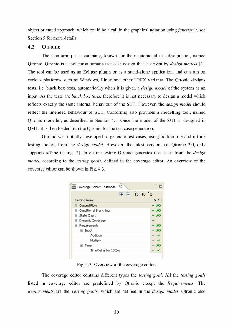
Fig. 4.3: Overview of the coverage editor.
The coverage editor contains different types the testing goal. All the testing goals
listed in coverage editor are predefined by Qtronic except the Requirements. The
Requirements are the Testing goals, which are defined in the design model. Qtronic also
31
shows how much of the Testing goals that are covered in terms of percentage. The Testing
goals for the example model (see Section 4.1), is shown in Fig. 4.3. All three Requirements,
defined in the example model, are covered by Qtronic. The Requirements in the design model
are defined in a hierarchy. For instance, the Requirements covered by user input and timeout
are defined under top level Requirements, i.e. Input and Timer, respectively. A globally
unique identifier could be use as a top level Requirement, so that it could be easier to track if
the design model contains too many Requirements.
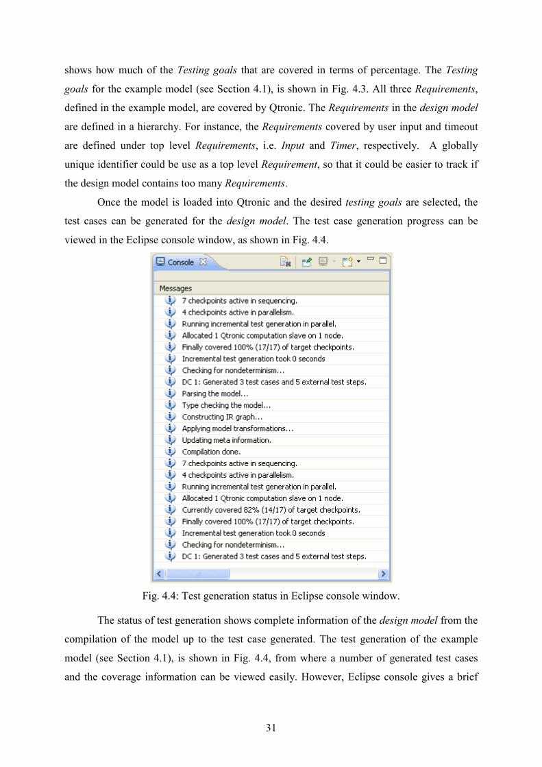
Once the model is loaded into Qtronic and the desired testing goals are selected, the
test cases can be generated for the design model. The test case generation progress can be
viewed in the Eclipse console window, as shown in Fig. 4.4.
Fig. 4.4: Test generation status in Eclipse console window.
The status of test generation shows complete information of the design model from the
compilation of the model up to the test case generated. The test generation of the example
model (see Section 4.1), is shown in Fig. 4.4, from where a number of generated test cases
and the coverage information can be viewed easily. However, Eclipse console gives a brief
32
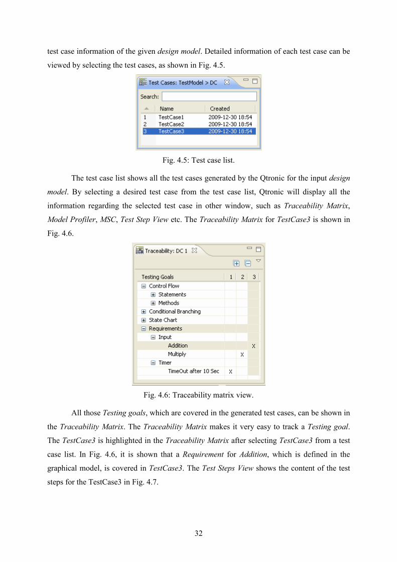
test case information of the given design model. Detailed information of each test case can be
viewed by selecting the test cases, as shown in Fig. 4.5.
Fig. 4.5: Test case list.
The test case list shows all the test cases generated by the Qtronic for the input design
model. By selecting a desired test case from the test case list, Qtronic will display all the
information regarding the selected test case in other window, such as Traceability Matrix,
Model Profiler, MSC, Test Step View etc. The Traceability Matrix for TestCase3 is shown in
Fig. 4.6.
Fig. 4.6: Traceability matrix view.
All those Testing goals, which are covered in the generated test cases, can be shown in
the Traceability Matrix. The Traceability Matrix makes it very easy to track a Testing goal.
The TestCase3 is highlighted in the Traceability Matrix after selecting TestCase3 from a test
case list. In Fig. 4.6, it is shown that a Requirement for Addition, which is defined in the
graphical model, is covered in TestCase3. The Test Steps View shows the content of the test
steps for the TestCase3 in Fig. 4.7.

33
Fig. 4.7: Test step view.
In Fig. 4.7, the records are shown along with their fields. For instance, in the first step
a Message of type record receives an event from an external input port in. Since it is defined
in the design model, that if the input number from the external input port in is between 0-10,
then the model will add 1 to the input value and sends the output to the external output port
out. Therefore, Qtronic had generated an input value of 5, and the model had responded with
the value of 6 to the output port out.
Qtronic also generates a MSC for all the generated test cases. The MSC for TestCase3
is shown in Fig. 4.8.
Fig. 4.8: MSC of TestCase3.
A MSC in Fig. 4.8 is showing the events and actions for the TestCase3. In Fig. 4.8, the
Tester and the MyObject are representing the Qtronic and the design model, respectively. The
Requirements, covered after any event or an action, are displayed in the MSC of the relevant
test case.

34
After generating the test cases successfully, the test scripts can be generated in order to
save the generated test cases, in order to use them afterwards. Qtronic provides means of
exporting the generated test cases into test scripts using scripting back-ends, shipped along
with the tool. These test scripts can be executed independently afterwards against the SUT.
The scripting back-ends shipped with Qtronic are:
• HTML
• TTCN-3
• TCL
However, if customer needs other back-ends it can be developed by Qtronic or
customer. The HTML is a scripting back-end, which can be browsed to see all the test
generation steps and information about the design model, generated by Qtronic. A TTCN-3
and TCL are the scripting back-ends which generates the test scripts for TTCN-3 and TCL
environment, respectively. In this thesis work, a TCL scripting back-end is used to generate
the test scripts. The test scripts, generated by Qtronic, using TCL scripting back-end contains:
• Test suit
• Test harness
• Template
The test suit contains all the test case generated by Qtronic. The test harness contains
all the routines/procedures used to communicate with the SUT, by sending and receiving data.
The Qtronic generates only the header of the routines/procedures in the test harness file,
which have to be implemented according to the specifications of the SUT.
For instance a TimeOut of type record, which is used in the example model (see
Section 4.1), will occur if the model does not receive an input from the Qtronic in 10 seconds.
Although the Qtronic will generate a test case for a timeout, but in practical Qtronic will not
exactly wait for 10 seconds to timeout. In fact Qtronic will only treat this timeout as a normal
event, and will generate a routine/procedure in the test harness for this TimeOut. Thus this
timeout, which is 10 seconds in this case, have to be implemented in the test harness.
Detailed information about the implementation of the test harness is described in Section 5.

35
5. Experiments
The model based testing (MBT) approach, applied on the three different versions of
the test object, will be described in this chapter. Each test object will be first modelled in
QML, and then loaded in Qtronic tool for test case generation. The test scripts, rendered in
TCL format, include all the test cases. A test harness will also be rendered in TCL format,
which includes all the Procedures defined in the model.
The test harness rendered by Qtronic only contains the definition of the procedures,
which shall be implemented according to the specifications defined in the test object. A Glue
Code will be developed to establish the test environment between the generated test cases and
the test object. The hierarchy of applying MBT approach on the different versions of test
object is shown in Fig. 5.1.
Fig. 5.1: The hierarchy of MBT applied on test objects.
The MBT technique is first applied on the pilot of PMc, and then on its extended
versions. Out of several possible MBT approaches, two different approaches are used to
Requirements for PMc
Pilot, X
PMc Internally Modified, X
PMc Extended, X
PMc , Y
R1 = Requirements added to Extend the PMc.
R2 = Requirements added for Internal Modification.
X = Implementing Logic in Model
Y = Implementing Logic in Glue
R1
R2
36
examine the flexibility of modelling the test object in Qtronic. These approaches were tested
on the final version of the PMc. In first approach, the logic of the test object is completely
designed in its model. However, in the second approach some of the logic from the model is
moved to the Glue. For convenience in describing the experiments, the substitute names for
all the different versions of PMC models are listed in Table 5.1.
Table 5.1: Substitute names for the different PMc.
Experiment Fo. PMc Versions Substitute Fames
1 Pilot Version A
2 PMc Extended Version B
3 PMc Internally Modified Version C
4 Implementing the logic in Glue Version D
5.1 Experiment 1
In this experiment the specifications, described in Section 3.3, are used to model and
generate the test cases for Version A of PMc. The FSM of the PMc, which is modelled in this
experiment, can be shown in Fig. 3.5.
5.1.1 Goals
The objectives of this experiment are:
• To model a FSM of Version A in QML.
• To generate the test cases from the model.
• To develop a test execution environment in order to execute the test cases against the
test object.
5.1.2 Modelling of the Version A
The model of the Version A is developed in such a way, so that further functionalities
could be added easily in the future. The methodology, described in the Section 3.2, is
followed by some means while modelling the Version A. The FSM in Fig. 3.5 is grouped in
sub-state machines in order to have a better overview of different types of transactions
implemented in PMc. The internal state machines of Authentication and Withdraw Money are
shown in Fig. B.0.1 and B.0.2, respectively. To have a better overview of the grouped states,
only the flows of successful transactions are shown in Fig. 5.2.
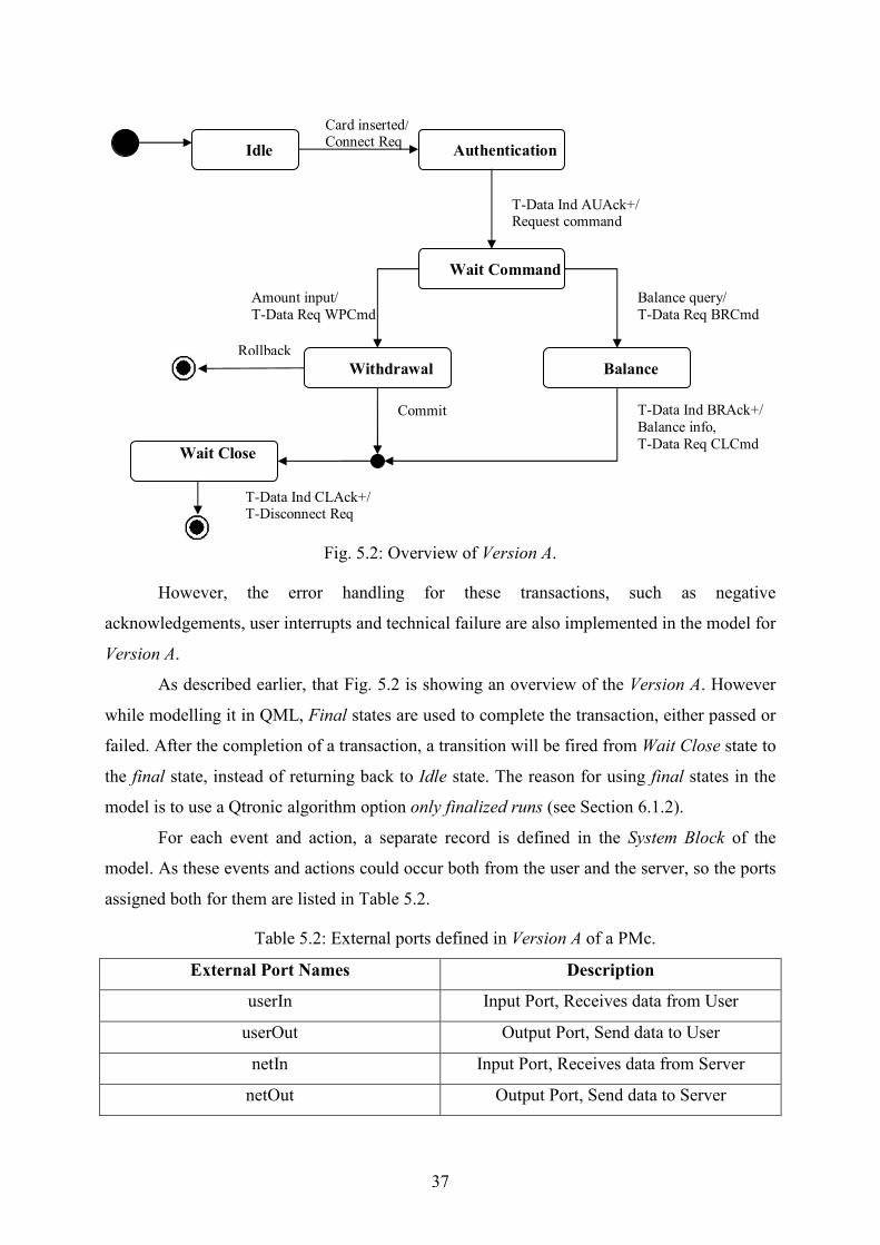
37
Rollback
Authentication
Balance
T-Data Ind AUAck+/ Request command
Withdrawal
Idle
Wait Close
Amount input/
T-Data Req WPCmd
Card inserted/ Connect Req
Balance query/
T-Data Req BRCmd
Commit T-Data Ind BRAck+/
Balance info,
T-Data Req CLCmd
Wait Command
T-Data Ind CLAck+/ T-Disconnect Req
Fig. 5.2: Overview of Version A.
However, the error handling for these transactions, such as negative
acknowledgements, user interrupts and technical failure are also implemented in the model for
Version A.
As described earlier, that Fig. 5.2 is showing an overview of the Version A. However
while modelling it in QML, Final states are used to complete the transaction, either passed or
failed. After the completion of a transaction, a transition will be fired from Wait Close state to
the final state, instead of returning back to Idle state. The reason for using final states in the
model is to use a Qtronic algorithm option only finalized runs (see Section 6.1.2).
For each event and action, a separate record is defined in the System Block of the
model. As these events and actions could occur both from the user and the server, so the ports
assigned both for them are listed in Table 5.2.
Table 5.2: External ports defined in Version A of a PMc.
External Port Fames Description
userIn Input Port, Receives data from User
userOut Output Port, Send data to User
netIn Input Port, Receives data from Server
netOut Output Port, Send data to Server
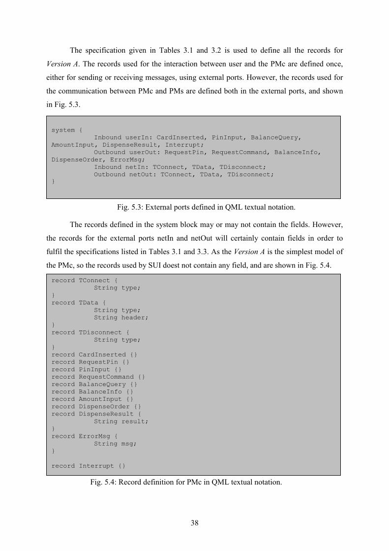
38
The specification given in Tables 3.1 and 3.2 is used to define all the records for
Version A. The records used for the interaction between user and the PMc are defined once,
either for sending or receiving messages, using external ports. However, the records used for
the communication between PMc and PMs are defined both in the external ports, and shown
in Fig. 5.3.
Fig. 5.3: External ports defined in QML textual notation.
The records defined in the system block may or may not contain the fields. However,
the records for the external ports netIn and netOut will certainly contain fields in order to
fulfil the specifications listed in Tables 3.1 and 3.3. As the Version A is the simplest model of
the PMc, so the records used by SUI doest not contain any field, and are shown in Fig. 5.4.
Fig. 5.4: Record definition for PMc in QML textual notation.
system { Inbound userIn: CardInserted, PinInput, BalanceQuery, AmountInput, DispenseResult, Interrupt; Outbound userOut: RequestPin, RequestCommand, BalanceInfo, DispenseOrder, ErrorMsg; Inbound netIn: TConnect, TData, TDisconnect; Outbound netOut: TConnect, TData, TDisconnect; }
record TConnect { String type; } record TData { String type; String header; } record TDisconnect { String type; } record CardInserted {} record RequestPin {} record PinInput {} record RequestCommand {} record BalanceQuery {} record BalanceInfo {} record AmountInput {} record DispenseOrder {} record DispenseResult {
String result; } record ErrorMsg { String msg; } record Interrupt {}

39
In the modelling of PMc, the ports responsible for the receiving the expected events,
i.e. UserIn and NetIn, are defined in the graphical notation of QML. However, the ports
responsible for sending the corresponding actions are defined in the textual notation of QML.
The illustration of these external ports in QML are shown in Fig. 5.5.
Fig. 5.5: Illustration of external port used for expected event.
The Fig. 5.5 shows a transition from idle state to authentication state. A transition will
trigger if an event CardInserted is received at the input port userIn. In response to that event,
an action will be executed and the current state will be change to authentication. A function
sendTConnect will be instantiated as an action. This function is defined in the textual notation
of QML, which will first create an instance of the record TConnect and then it will assign the
value Req to the field type, as shown in Fig. 5.6.
Fig. 5.6: Function definition in QML textual notation.
This function will send the action to Qtronic using external output ports. The record
TConnect is also used to receive an expected event in the QML model. The field defined for
the record TConnect is type and it will be used as a guard. If the statement in the guard
becomes true, an action in the response will be executed and the current state will be updated
accordingly, as shown in Fig. 5.7.
public void sendTConnect(String type){ TConnect r; r.type = type; netOut.send(r); } public void sendTData(String type, String header){ TData r; r.type = type; r.header = header; netOut.send(r); }
40
Fig. 5.7: Reusing a record in QML.
The Fig. 5.7 shows the internal behaviour of the basic state authentication. After
receiving a TConnect Req from the model, Qtronic will respond either with Conf+ or Conf-.
The Fig. 5.7 shows the positive acknowledgement from the Qtronic, i.e. Conf+, and in the
response a function sendTData will be executed as action. The function sendTData will first
create an instance of the record TData, and then it will assign the corresponding parametric
values to both the fields i.e. type and header.
Similarly, the record TData is used both for sending and receiving the commands.
However, the different combinations of the parameters in the guard for the record TData are
used to produce all the expected events and actions listed in Tables 3.1-3.3.
The error handling is also considered while modelling the test object. The two types of
expected errors, which could occur during the ongoing transaction are Interrupt from the user
and a TDisconnect Ind from the server in case of a technical failure.
Fig. 5.8: illustration of error handling in PMc model.
These errors are handled using internal transitions which are written in the state,
shown in Fig. 5.8. These internal transitions, if become true, cannot fire a transition from one

41
state to another state. Therefore, a Boolean value will be used in order to change the state, if
an expected event occurs. In Fig. 5.8, a transition from the state Wait Balance to the final state
will be fired if the expression in the guard becomes true.
The first internal transition will occur due to an interrupt from the external port
userIn. The action in response to this event will be a TDisconnect Req, and a Boolean
isInterrupted will be set to true. Similarly, the second internal transition will occur due to a
disconnect indication from the external port netIn, which in response sends an error message
to the user and will set the Boolean IsDisconnected to true.
5.1.3 Settings for Test Case Generation
After creating the model of the test object using graphical and textual notation in
QML, the model is then imported into the Qtronic. To enable the Test Design Configuration
settings, the model has to be loaded in Qtronic Computation Server (QCS). Once the model is
loaded, testing goals can be defined using Coverage Editor. The coverage goals are used to
guide the Qtronic to cover the desired behaviour of the model.
Other then pre-defined testing goal possibilities in the Test Design Configuration, a
number of Requirements are also added in the model to determine the coverage of desired
behaviour. These Requirements are defined in the graphical notation of the model, as shown
in Fig. 5.7 and 5.8. In the Coverage Editor, only the Requirements are targeted for the
generation of the test cases for Version A. The Requirements in the model are defined after
every expected event, listed in Tables 3.1-3.3. These Requirements, defined in the graphical
notation, are grouped for each of the external input port, as shown in the Fig. 5.9.
Fig. 5.9: Testing goals for Version A.
The requirements defined for user are listed under the keyword UserIn. Similarly the
requirements defined for the incoming messages from PMs are listed under netIn. The Testing
goals are 0% before generating the test cases. The Qtronic algorithmic options e.g. Only
Finalized Runs, Lookahead Depth etc, are also used for the generation of the test cases (see
Section 4).

42
5.1.4 Implementation of the Test Harness and Test Execution
Environment. The test cases generated from the model are exported in TCL script format, using a
TCL backend scripter. A TCL backend scripter, already included in the Qtronic tool, is added
in the Test Design Configuration of the model. The generated test cases are rendered to
generate a test suite and test harness in a TCL format. The test suite contains all the generated
test cases in a single file. The test suite is then executed, independently from Qtronic, against
the test object afterwards. One of the test cases generated from the model of Version A in a
test suite is shown in Fig. 5.10:
Fig. 5.10: Test cases generation from the model of Version A in a test suite.
The test harness contains all the procedures, responsible for the transfer of data
between the test suite and the test object. The headers of these procedures are created by
Qtronic itself, using the records defined in the system block. The parameter of these
procedures represents the fields, defined for the records in the model. However the body of
these procedures have to be implemented afterwards, according to the specification of the test
object. The Qtronic will append a port name, as a prefix to these records, for creating the
procedures in the test harness. Two of several procedures in the test harness are shown in Fig.
5.11.
source TestHarness.tcl proc "TestCase1" {} \ { traceprint "Action: Tester sends inbound event CardInserted to port userIn" userInCardInserted traceprint "Action: SUT is expected to response with outbound event TConnect from port netOut" set type_1 "Req" netOutTConnect $type_1 traceprint "Action: Tester sends inbound event TConnect to port netIn" set type_2 "Conf-" netInTConnect $type_2 traceprint "Covered requirement: requirement: netIn/TConnect Conf-" traceprint "Action: SUT is expected to response with outbound event ErrorMsg from port userOut" set msg_3 "Error message: Connection not established" userOutErrorMsg $msg_3 }

43
Fig. 5.11: Procedure definition in TCL format.
The procedure netInTData is responsible for sending an event to the test object. This
procedure will be called in a test suite, with some input parameters, generated from the
Qtronic. The procedure netOutTData will receive an action from the test object. An expected
message is assigned a value within the procedure, in order to compare it with the actual
received message. A keyword vwait is used to make sure that a procedure does not exit until
it receives an action from the test object.
After implementing the test harness, a test interface is established to execute the
generated test scripts against the test object. As the test object is developed in a Java platform
and the test scripts were generated and implemented in a TCL format, therefore the interface
is established using socket programming. The data transfer between test scripts and the test
object takes place via sockets. An overview of the test execution environment can be shown
in Fig. 5.12.
Fig. 5.12: Overview of the test execution environment.
The execution of test scripts against the SUT will start by calling the test cases one by
one from the test suite. In general, the test scripts send an event to the SUT using a socket.
The SUT will respond to the event with a corresponding action via socket. For every response
from the SUT, a verdict procedure in the test script will compare the expected message with
Main Test Suite Test Harness Socket SUT Socket
Test Scripts
Test Interface Test
Object
Source socket.tcl proc netOutTData { type header } { \ global expected received set expected "T-Data $type $header" vwait received } proc netInTData { type header } { \ global sockChan set msg "T-Data $type $header" send $sockChan $msg }

44
the actual received message. After executing the complete test case against the SUT, the
verdict procedure will declare either the test case passed or failed. Thus a list of passed or
failed test cases will be stored in a log file for further evaluation.
5.2 Experiment 2
This experiment is performed to analyse the adaption performance of Qtronic by
extending the existing model of a Version A in QML. Some parameters for the existing
features are also introduced, in order to make the user interface look like as a real ATM. The
specifications, described in Section 3.4, are used to develop this model in QML.
5.2.1 Goals
The aim of this experiment can be divided into four parts:
• To evaluate how well suited Qtronic is for incremental design.
• To provide more transaction options to the user, by including two more functionality
in existing Version A.
• Introduce some parameters to facilitate and acquire some information, about the
ongoing transaction, from the user.
• Due to these extensions in the model, the test harness which was implemented earlier
should be modified and updated accordingly.
5.2.2 Modelling of the Version B
The modelling of the Version B will be described according to the specified goals,
respectively. The model of the Version B is basically developed by enhancing the existing
model of Version A in QML. The two additional options introduced for user, i.e. Deposit
Money and Transfer Money, are modelled for Version B using the specification defined in
Section 3.4.
The Authentication state is responsible for the authentication of user’s bank Id, and
Pin Input. If the authentication is passed then the user will be asked to select any of the four
options available to precede the transaction. However, if the authentication is failed, then the
session will be closed. Thus after completing a transaction, either successful or unsuccessful,
the session will be closed and the state machine will return to Idle state. The expected errors
for additional functionalities are also implemented, such as a user interrupt, a technical failure
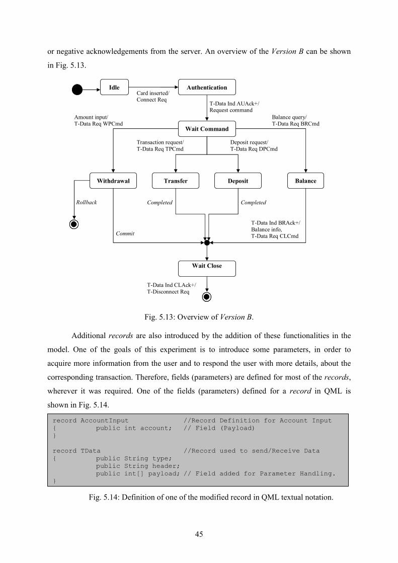
45
or negative acknowledgements from the server. An overview of the Version B can be shown
in Fig. 5.13.
Rollback
Authentication
Balance
T-Data Ind AUAck+/ Request command
Withdrawal
Idle
Wait Close
Amount input/ T-Data Req WPCmd
Card inserted/ Connect Req
Balance query/ T-Data Req BRCmd
Commit
T-Data Ind BRAck+/
Balance info, T-Data Req CLCmd
Wait Command
T-Data Ind CLAck+/
T-Disconnect Req
Transfer Deposit
Completed Completed
Transaction request/
T-Data Req TPCmd
Deposit request/
T-Data Req DPCmd
Fig. 5.13: Overview of Version B.
Additional records are also introduced by the addition of these functionalities in the
model. One of the goals of this experiment is to introduce some parameters, in order to
acquire more information from the user and to respond the user with more details, about the
corresponding transaction. Therefore, fields (parameters) are defined for most of the records,
wherever it was required. One of the fields (parameters) defined for a record in QML is
shown in Fig. 5.14.
Fig. 5.14: Definition of one of the modified record in QML textual notation.
record AccountInput //Record Definition for Account Input { public int account; // Field (Payload) } record TData //Record used to send/Receive Data { public String type; public String header; public int[] payload; // Field added for Parameter Handling. }
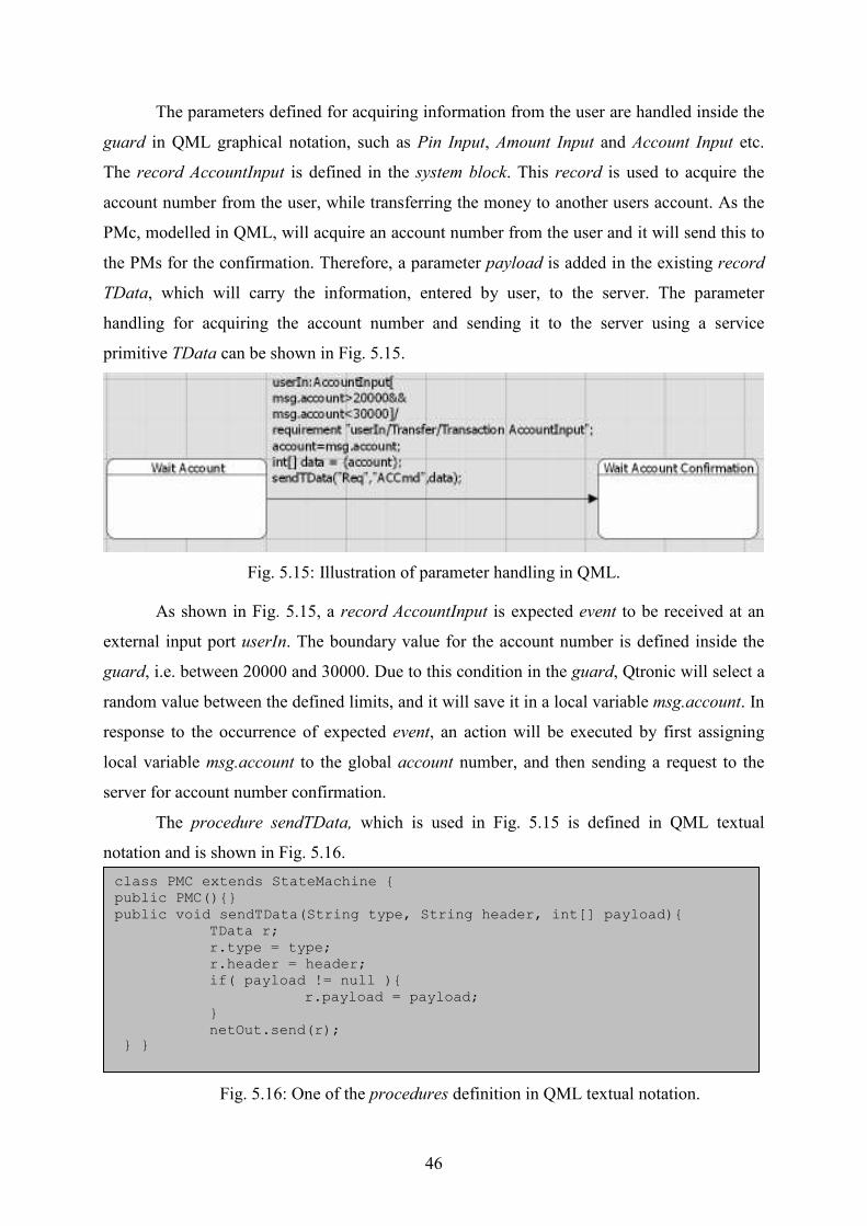
46
The parameters defined for acquiring information from the user are handled inside the
guard in QML graphical notation, such as Pin Input, Amount Input and Account Input etc.
The record AccountInput is defined in the system block. This record is used to acquire the
account number from the user, while transferring the money to another users account. As the
PMc, modelled in QML, will acquire an account number from the user and it will send this to
the PMs for the confirmation. Therefore, a parameter payload is added in the existing record
TData, which will carry the information, entered by user, to the server. The parameter
handling for acquiring the account number and sending it to the server using a service
primitive TData can be shown in Fig. 5.15.
Fig. 5.15: Illustration of parameter handling in QML.
As shown in Fig. 5.15, a record AccountInput is expected event to be received at an
external input port userIn. The boundary value for the account number is defined inside the
guard, i.e. between 20000 and 30000. Due to this condition in the guard, Qtronic will select a
random value between the defined limits, and it will save it in a local variable msg.account. In
response to the occurrence of expected event, an action will be executed by first assigning
local variable msg.account to the global account number, and then sending a request to the
server for account number confirmation.
The procedure sendTData, which is used in Fig. 5.15 is defined in QML textual
notation and is shown in Fig. 5.16.
Fig. 5.16: One of the procedures definition in QML textual notation.
class PMC extends StateMachine { public PMC(){} public void sendTData(String type, String header, int[] payload){ TData r; r.type = type; r.header = header; if( payload != null ){ r.payload = payload; } netOut.send(r); } }
47
A dynamic array of data is allocated for the payload. Thus in case of more then one
payload, the length of data will be allocated accordingly. For example, when an event Card
inserted will be occurred, two different payload values will be used in this case, i.e.
card,umber and bankId. Thus the length of the dynamic array data will be 2 in this case. The
request for account confirmation, along with the account number as a payload, will be sent to
the server using external output port netout.
5.2.3 Settings for Test Case Generation
The extended model, i.e. Version B, will be loaded again in the Qtronic. After loading
the model, the Test Design Configurations will be updated automatically according to the
modifications made in the model. In Version B, the Requirements are first grouped according
the events received by the model from the external input ports. Then these Requirements are
further grouped individually for each transaction option. Such as, all the Requirements
defined in the Transfer Money transaction are included in one group. Therefore, all these
Requirements in the corresponding group will be displayed in the Coverage Editor as a
Testing goal.
The grouping makes it easier to track the Requirement covered in the test cases. The
Requirements are the only Testing goal selected to generate all the possible test cases in
Version B. One of the Qtronic algorithmic options, i.e. Lookahead Depth, used to generate the
test cases for the Version B is 2. Another option, Only Finalized Runs, is also selected for the
generation of test cases.
5.2.4 Implementation of the Test Harness and Test Execution Environment
In this experiment, the test cases generated from the model are exported in TCL script
format as before, using a TCL backend scripter. A TCL backend scripter is again added for a
new Test Design Configuration for Version B. The generated test cases are rendered to
generate a test suite and test harness in a TCL format. While executing the test cases against
the SUT, the external ports userIn and netIn will be used to send the data from a Tester to
SUT, and the external ports userOut and netOut will be used to receive the data from SUT to
a Tester (see Section 5.1.4).
In TestCase37, the Tester will first send the account number, generated by Qtronic i.e.
25000, to the SUT using a procedure userInAccountInput. The SUT is then expected to

48
response with the account confirmation request, along with the account number as a payload.
Few lines of code of Testcase37 are shown in Fig. 5.17.
Fig. 5.17: Few lines of code of Testcase37 in TCL format.
The test harness generated for Version A in Experiment 1 is reused in this experiment.
Although, numbers of procedures are included in the test harness due to extension and
modifications made in the model, however, some of the existing procedures in the test harness
are also modified for Version B, such as netInTData, netOutTData, UserInCardInserted etc.
The existing procedures in the test harness are modified mainly due to the addition of a
payload in the Version B. In test harness, payload is appended using a separator ‘/’, e.g.
‘Account Input / 25000’ in the case described above. The separator ‘/’ is used so that SUT can
distinguish between an input message, i.e. Account Input, and a payload, i.e. 25000. In
procedure netOutTData, the an expected response from the SUT will compared with actual
response. Thus on the basis of this comparison a verdict will be declared, by either affirming
the test case passed or failed.
Two of the procedures implemented in the test harness and used in TestCase37 are
shown in Fig. 5.18.
source TestHarness.tcl proc "TestCase37" {} \ { … … … traceprint "Action: Tester sends inbound event AccountInput to port userIn" set account_753 25000 userInAccountInput $account_753 traceprint "Covered requirement: requirement: userIn/Transfer/Transaction AccountInput" traceprint "Action: SUT is expected to response with outbound event TData from port netOut" set type_754 "Req" set header_755 "ACCmd" set payload_756 {25000} netOutTData $type_754 $header_755 $payload_756 … … … }
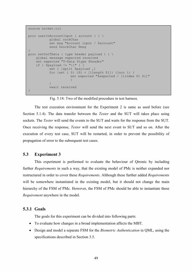
49
Fig. 5.18: Two of the modified procedure in test harness.
The test execution environment for the Experiment 2 is same as used before (see
Section 5.1.4). The data transfer between the Tester and the SUT will takes place using
sockets. The Tester will send the events to the SUT and waits for the response from the SUT.
Once receiving the response, Tester will send the next event to SUT and so on. After the
execution of every test case, SUT will be restarted, in order to prevent the possibility of
propagation of error to the subsequent test cases.
5.3 Experiment 3
This experiment is performed to evaluate the behaviour of Qtronic by including
further Requirements in such a way, that the existing model of PMc is neither expanded nor
restructured in order to cover these Requirements. Although these further added Requirements
will be somewhere instantiated in the existing model, but it should not change the main
hierarchy of the FSM of PMc. However, the FSM of PMc should be able to instantiate these
Requirement anywhere in the model.
5.3.1 Goals
The goals for this experiment can be divided into following parts:
• To evaluate how changes in a broad implementation affects the MBT.
• Design and model a separate FSM for the Biometric Authentication in QML, using the
specifications described in Section 3.5.
source socket.tcl proc userInAccountInput { account } { \ global sockChan set msg "Account input / $account" send $sockChan $msg } proc netOutTData { type header payload } { \ global message expected received set expected "T-Data $type $header" if { $payload != "{}" } { set l [split $payload ,] for {set i 0} {$i < [llength $l]} {incr i} { set expected "$expected / [lindex $l $i]"
} } vwait received
}

50
• Instantiate this Biometric Authentication FSM in the PMc model for each of the
transaction option individually.
• Update the test harness for the newly introduced Requirements.
5.3.2 Modelling
In the Version C of the PMc a new state machine is added, to construct the model of
Biometric Authentication process, in order to cover the Requirements described in Section 3.5.
The purpose of the Biometric Authentication is to verify the user, who is operating the ATM,
by taking his iris information using a camera installed in ATM. The ATM will also send its
own identity number to the server for the verification along with the acquired iris information
from the user. A detailed description of data transmission between the PMc and PMs is
discussed in Section 3.5. Therefore, only the implementation of Biometric Authentication in
QML and its interaction with the PMc model will be described in this Section. As specified in
the goals that the Biometric Authentication process could be started from any state within the
model of PMc. Therefore the instantiating of the Biometric Authentication process in a state
Wait Transfer is shown in Fig. 5.19.
Fig. 5.19: Illustration of instantiating Biometric Authentication in PMc model.
The Biometric Authentication process is usually invoked in the states after user enter
the Amount input. In case of transfer money to another account, the user will be first asked to
enter the account number of the recipient. After the confirmation of the recipient account
number, user will enter the amount to be transferred. Thus before transferring the amount to
the desired account, a Biometric Authentication process will be started in order to confirm if
the owner of the ATM card is himself transferring the money to another account. In Fig. 5.19,
an if-else statement is used to guide the Qtronic to cover both the Requirements for positive

51
and negative acknowledgements. The updates made in PMc textual notation are shown in Fig.
5.20.
Fig. 5.20: Function definition of Biometric Authentication in QML textual notation.
As described earlier, that the Biometric Authentication is a separate state machine.
Therefore, an internal communication will takes place between the two state machines in
QML, i.e. PMc model and Biometric Authentication model. For internal communication, CQ
ports are used for the transmission of data between two state machines. After invoking the
Biometric Authentication, the PMc state machine will be paused until it receives a response
from the Biometric Authentication state machine. A require statement is used to force the
Qtronic to wait until it receives an internal message of Biometric acknowledgement from the
Biometric Authentication state machine.
The QML model for Biometric Authentication, as described earlier, is designed in a
separate FSM. In Fig. 5.21, initially a PMc model will receive a Seed from the PMs, using an
external input port netIn. A require statement is used to tell Qtronic what value is exactly
needed in this model. For instance a require statement is used first to allocate the length of the
payload parameter for Seed, and then to generate a random Seed Id as a payload. After
receiving a Seed from the PMs, the PMc model will send a Biometric Request to the user
using a function sendBioRequest().
Subsequent to the Biometric Request to the user, the user will response with the
irisInfo using an external input port userIn. Thus the PMc model will send all the information,
i.e. user’s iris information, Seed code from the server and its own ATM id, to the PMs using a
function sendTData(). In case the Biometric Authentication is verified, a positive
acknowledgment will be received by PMc model and the corresponding transaction will be
class PMC extends StateMachine { CQPort internalIn; public PMC(CQPort in){ internalIn = in; } public void BiometricAuthentication(){ BioAuth bio = new BioAuth(internalIn); bio.start("Biometric Authentication"); internalMsg r = (internalMsg) internalIn.receive(); require r.type == "BiometricAuth"; require r.header=="Conf+" || r.header=="Conf-"; if(r.header=="Conf-") bioAuthError=true; } }
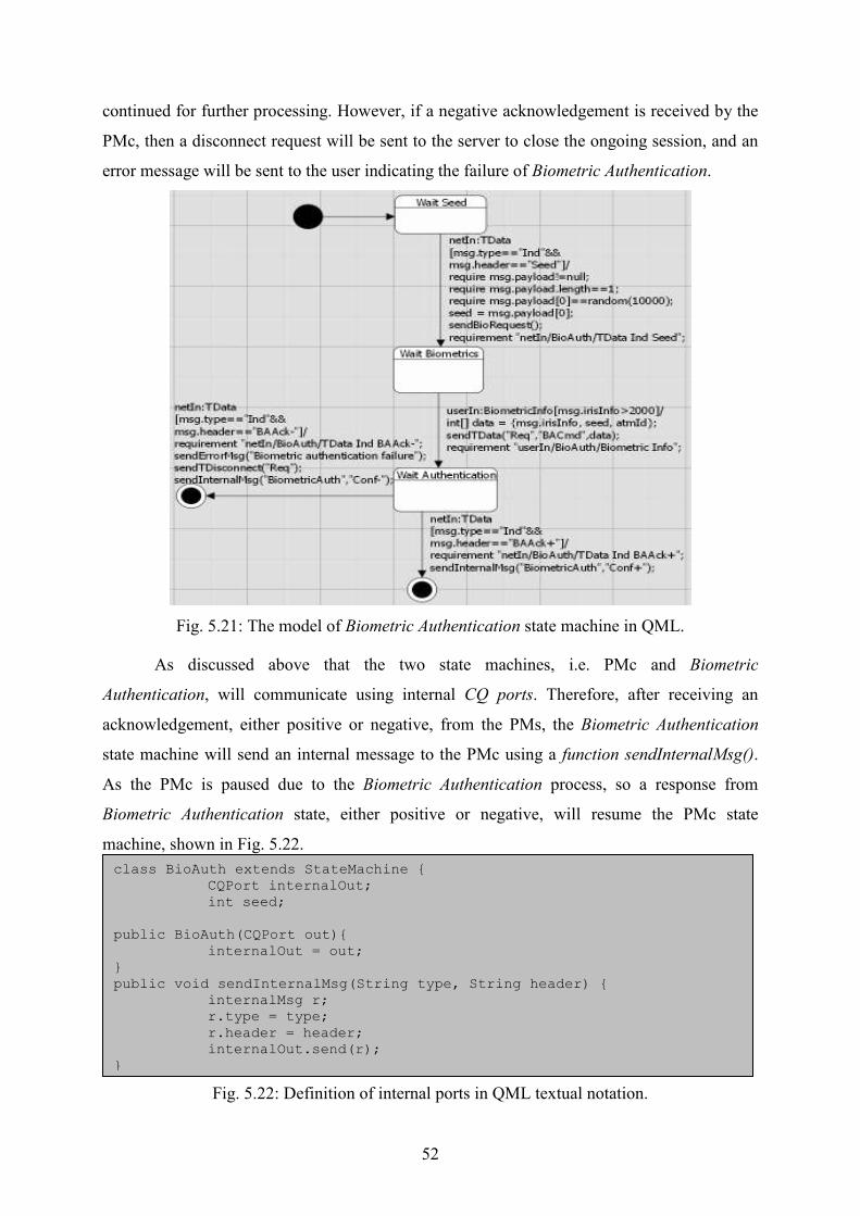
52
continued for further processing. However, if a negative acknowledgement is received by the
PMc, then a disconnect request will be sent to the server to close the ongoing session, and an
error message will be sent to the user indicating the failure of Biometric Authentication.
Fig. 5.21: The model of Biometric Authentication state machine in QML.
As discussed above that the two state machines, i.e. PMc and Biometric
Authentication, will communicate using internal CQ ports. Therefore, after receiving an
acknowledgement, either positive or negative, from the PMs, the Biometric Authentication
state machine will send an internal message to the PMc using a function sendInternalMsg().
As the PMc is paused due to the Biometric Authentication process, so a response from
Biometric Authentication state, either positive or negative, will resume the PMc state
machine, shown in Fig. 5.22.
Fig. 5.22: Definition of internal ports in QML textual notation.
class BioAuth extends StateMachine { CQPort internalOut;
int seed; public BioAuth(CQPort out){ internalOut = out; } public void sendInternalMsg(String type, String header) { internalMsg r; r.type = type; r.header = header; internalOut.send(r); }
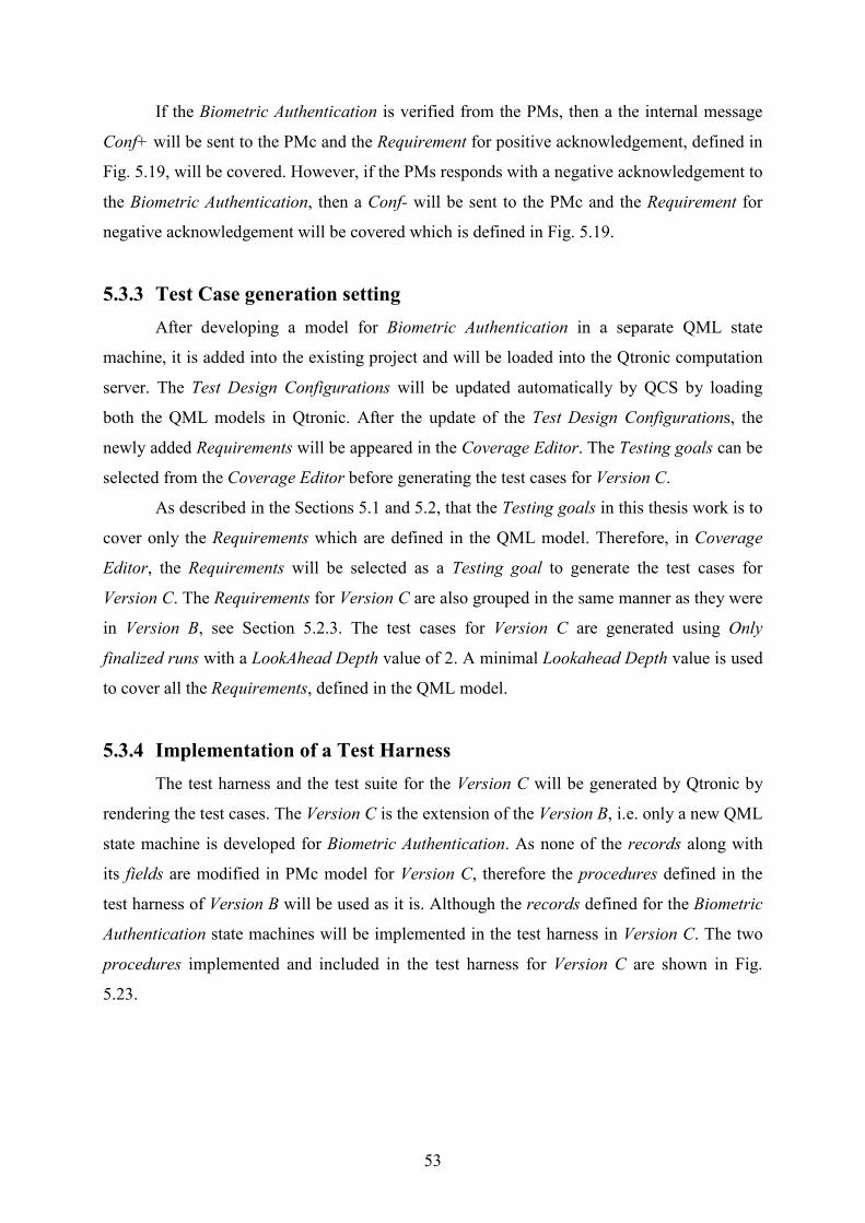
53
If the Biometric Authentication is verified from the PMs, then a the internal message
Conf+ will be sent to the PMc and the Requirement for positive acknowledgement, defined in
Fig. 5.19, will be covered. However, if the PMs responds with a negative acknowledgement to
the Biometric Authentication, then a Conf- will be sent to the PMc and the Requirement for
negative acknowledgement will be covered which is defined in Fig. 5.19.
5.3.3 Test Case generation setting
After developing a model for Biometric Authentication in a separate QML state
machine, it is added into the existing project and will be loaded into the Qtronic computation
server. The Test Design Configurations will be updated automatically by QCS by loading
both the QML models in Qtronic. After the update of the Test Design Configurations, the
newly added Requirements will be appeared in the Coverage Editor. The Testing goals can be
selected from the Coverage Editor before generating the test cases for Version C.
As described in the Sections 5.1 and 5.2, that the Testing goals in this thesis work is to
cover only the Requirements which are defined in the QML model. Therefore, in Coverage
Editor, the Requirements will be selected as a Testing goal to generate the test cases for
Version C. The Requirements for Version C are also grouped in the same manner as they were
in Version B, see Section 5.2.3. The test cases for Version C are generated using Only
finalized runs with a LookAhead Depth value of 2. A minimal Lookahead Depth value is used
to cover all the Requirements, defined in the QML model.
5.3.4 Implementation of a Test Harness
The test harness and the test suite for the Version C will be generated by Qtronic by
rendering the test cases. The Version C is the extension of the Version B, i.e. only a new QML
state machine is developed for Biometric Authentication. As none of the records along with
its fields are modified in PMc model for Version C, therefore the procedures defined in the
test harness of Version B will be used as it is. Although the records defined for the Biometric
Authentication state machines will be implemented in the test harness in Version C. The two
procedures implemented and included in the test harness for Version C are shown in Fig.
5.23.
54
Fig. 5.23: The two procedures added in test harness for Biometric Authentication.
Now the important thing, while execution of the test cases against the SUT, is that the
procedures starts with userIn and netIn will be used to send data packets to SUT. Moreover,
the procedures in the test harness starting with userOut and netOut are used to receive the
response from the SUT. However, this is opposite while modelling the test object in QML,
see Section 6.1.2. Thus by receiving a biometric request from the SUT, Tester will send user’s
iris information in response to the SUT using the procedure userInBiometricInfo.
5.4 Experiment 4
In the previous three experiments, a pilot is first modelled in the QML and then it is
enhanced step by step using the specifications, described in Sections 3.3 – 3.5. After the
successful execution of the test scripts, for all three versions, against the SUT, the
performance of Qtronic is investigated by moving the logic, which is presently implemented
in model, to the test harness. The SUT in this case will not be modified in any perspective and
the test object developed for Experiment 3 will be used as a SUT in this experiment as well.
5.4.1 Goals
The goals for this experiment can be divided into following parts:
• Revise the model of Version C and remove some of the parameters from the model in
order to be added in test harness.
• Update the test harness by handling those parameters, which will be removed from the
model.
proc userInBiometricInfo { irisInfo } { \ global sockChan set msg "Biometric info / $irisInfo" send $sockChan $msg } proc userOutRequestBiometrics { } { \ global expected received set expected "Request biometric code" vwait received }

55
5.4.2 Modelling
The model of PMc, developed for Version C, will be used to examine the effectiveness
of moving some of the logic from the model to the test harness. As the test object modelled in
QML is not too complex, therefore only some parameters which are handled in model will be
tackled in the test harness in this experiment. Mostly the parameters used in the model are
somehow related for the generation of the expected events or their corresponding actions.
For instance, in Fig. 5.26 the parameters msg.account is used to guide Qtronic to
generate the expected event, from the corresponding interface i.e. userIn, in the certain
defined limits. Therefore the parameters, on which the generation of the test case depends,
cannot be moved to the test harness. Thus, in order to evaluate the performance of Qtronic, by
moving the logic to the test harness, the parameters which are not taking part in the test
generation of the model will be considered. After analyzing the model, a parameter which was
carrying the payloads, defined in the record TData, will be moved from the model. The
modified record definition of TData for Version D is shown in Fig. 5.24.
Fig. 5.24: Modified record definition for Version D in QML textual notation.
For now, as the payload parameter will be handled in the test harness, therefore a field
of payload will be removed from the definition of a record TData. The TData will now only
comprise of two parameters, i.e. type and a header. Subsequently, the function sendTData,
used to carry these parameters will also be modified both in the textual and in the graphical
notation of PMc model. The modified function sendTData for Version D is shown in Fig.
5.25.
Fig. 5.25: Modified function sendTData for Version D in QML textual notation.
record TData { public String type; public String header; }
class PMC extends StateMachine { public void sendTData(String type, String header){ TData r; r.type = type; r.header = header; netOut.send(r); } }

56
As described earlier, by removing the parameter payload from the model will affect
neither the MSC of test cases nor the number of test cases generated by Qtronic. For instance,
in Fig. 5.15 Qtronic is first generating the account number, within the specified limits, and
then the function sendTData will carry the account number along with the account
confirmation request to the PMs. However, in case of removing the payload from the record
TData, the Qtronic is still generating the account number, within the specified limits, but the
generated account number is not carried by the function sendTData. The graphical notation of
Version D, in which the payload is not carried as before, is shown in Fig. 5.26.
Fig. 5.26: Illustration of transmitting data packet without a payload.
In the QML model of the Version C, a dynamic integer array was instantiated to carry
the payloads as a parameter. However, by removing the payload from the model, a dynamic
integer array will not be created by Qtronic each time it sends an action using a function
sendTData.
5.4.3 Test Case Generation and Setting
The model of Version D will be loaded into the QCS, after modifying it to the
specified goals defined in Section 5.4.1. Since no new Requirements are added in the model
of Version D as compared to the Version C except of removing some of the parameters from
the model. Therefore, the number of Requirements will be same as they were for Version C.
Hence the Requirements will be selected as a Testing goal for this experiment as well.
The test cases will be generated as only finalized runs with the Lookahaed Depth of 2.
A minimal value of Lookahead Depth is used to get a complete coverage of the Requirements,
which were defined in the model.

57
5.4.4 Implementation of the Test Harness
The test cases generated for the Version D will be rendered to generate the test suite
and the test harness. As the model for Version D is not extended, therefore the number of
procedures generated in the test harness will be same as they were for Version C. The
parameter payload, which is removed from the model, will mainly be handled in the test
harness procedures, such as netOutTData and netInTData. Two of the many procedures,
implemented in the test harness for Version D are shown in Fig. 5.27.
Fig. 5.27: Two of the Procedures modified in the test harness of Version D.
To handle the payload parameters, some global variables are defined in the test
harness. In the procedure netOutTData, a payload will be added to the corresponding data
packet after verifying the related header. For instance the account number generated by
Qtronic, shown in Fig. 5.26, will first be saved in a temporary global variable acnt in a
procedure userInAccountIput. Moreover, if the procedure netOutTData receives ACCmd as a
header, then it will append the account number, i.e. acnt, after the corresponding header.
5.5 Summary
In this chapter, the QML models were created for all versions of the SUT. These QML
models were used to generate the test cases using Qtronic. The test harness is implemented in
proc userInAccountInput { account } { \ global sockChan global acnt set acnt $account set msg "Account input / $account" send $sockChan $msg } proc netOutTData { type header } { \
global expected received global acnt
set payload "" if { $header == "ACCmd" } { set payload "$acnt" } if { $payload != "" } { set expected "T-Data $type $header / $payload" } else { set expected "T-Data $type $header" } vwait received }

58
order to execute the generated test cases against the SUT. A test execution environment is
developed to perform the tests against the SUT. The modelling of the SUT is performed using
two different approaches. In the first three experiments, the logic of the SUT is completely
defined in the QML model. However, in experiment four, some of the logic from the model
was moved to test harness, in order to evaluate the performance of Qtronic.

59
6. Results and Analysis
The experiments performed for all the three versions of the test object will be analysed
in this chapter. The analysis will based on the results and will primarily focus on the different
aspects of the behaviour of Qtronic towards the model. The methodology for expanding the
model, in case of additional requirement, is also investigated. The results for each experiment
performed are described individually, and these results are analyzed and evaluated on the
basis of the experiences, faced while achieving the goals.
6.1. Experiment 1
6.1.1. Results
The Test Design Configuration for generating the test cases for Version A are only
based on covering Requirements, defined in the model. The Qtronic will at least cover these
Requirements once, while generating the test cases. Different values of the Lookahead Depth
were chosen while generating the test cases for the model, in order to cover the entire
Requirements. The complete coverage of the Requirements for Version A was achieved for a
Lookahead Depth value of 1. The generated test cases, Requirements covered and MSC of
Version A is shown in the Fig. 6.1.
Fig. 6.1: Overview of generated test cases and coverage results of Version A.

60
Fig. 6.1 shows some of the information after generating the test cases for the model of
Version A. The MSC of TestCase2 is shown in Fig. 6.1, which is indicating a Requirement
covered by Qtronic by a keyword R. However, the Requirements covered in different test
cases can also be viewed in a Traceability Matrix, see Section 4. The other important
parameters considered during the modelling and generation of the test cases for Version A are
listed in Table 6.1.
Table 6.1: Results of Experiment 1.
Modeling time 2 days
Test generation time 13 seconds
Test design configuration coverage 100%
Number of generated test cases 25
Time to implement test harness 2 days
Lines of code: Test suite 2860
Number of test harness procedures 18
Lines of code: Test harness 99
Average: LOC / Harness procedure 5.5
Lines of code: Test execution environment 73
The modelling time for Version A is two complete working days, i.e. 16 hours in total.
This model was implemented after attending the course on Qtronic. The instructor from
Qtronic gave some basic guidelines for modelling in a more structured way. The initial
structure of the model was also important, because the model have to be expanded and
modified later in the future, after including additional requirements.
The test generation time is calculated by Qtronic every time it generates the test cases
using QCS. In this experiment, the Requirements defined in the model will only be selected as
a testing goal in the Test Design Configuration. The other Testing goals in the Test Design
Configuration are targeted as don’t care. The complete coverage of the Requirements results
in generating 25 test cases for Version A.
The test harness and test execution environment were implemented in two complete
working days. The time consumed for the implementation of the test execution environment
also includes the execution of the test cases against the SUT. The number of test harness
procedures is generated by the Qtronic, which depends upon the number of records defined
for external input and output ports. The lines of code in test harness shows the work required

61
to make the test suite up and running. A log file is generated while the test cases are executed
against the SUT. This log file contains all the information of expected and actual messages
along with the result of the test case, which can be either pass or fail. These results are also
displayed during the execution of the test cases against the SUT, as shown in Fig. 6.2.
Fig. 6.2: Execution of test cases against SUT and its test results.
Some of the test cases executed against the SUT were failed initially. The first reason
was a mismatch between the expected and actual messages. And the second reason was, that
in some cases due to failure of a single test case, SUT could not restarted from Idle state,
which results in propagating the error to the execution of next test cases. And eventually all
ends up with the failure of the subsequent test cases. Therefore, to prevent the subsequent test
cases from the propagation of this error, SUT restarts before the execution of each test case.
6.1.2. Analysis
The modelling and test case generation of Version A in Qtronic not only gives insight
knowledge of this automation tool, but it also gives a new approach of applying model based
testing. While modelling a test object, a tester should keep in mind that the test object could
be extended or modified in future by adding or removing some of its features. Therefore, a
suitable design pattern should be chosen before modelling the test object, so that a model can
be extended or modified easily according to the changes made in test object.
62
As the MBT technique is generally used for Black Box Testing, hence external input
and output ports are more considered while modelling the test object. The number of external
ports could be increased as model grows by adding more Requirements. Moreover this could
make the model more complex if the record names of each input and output port are defined
separately.
For example, the same record name TData is defined both for the external ports, netIn
and netOut, in system block. However, the fields of the record TData is defined only once
(see Section 5.1.2), which is used by both the external ports. Hence, Qtronic allows the tester
to reuse the record names for his ease, while modelling a complex test object.
While modelling the test object in QML all the records defined for external ports,
userIn and netIn, were used to receive the messages from Qtronic. However, while
implementing the test harness, these records were used to send the messages to the SUT.
A Qtronic algorithmic option, i.e. Only finalized runs, is used to make sure that every
test case, generated by Qtronic, ends up with an exit to the model. The exit to the model could
occur either due to any interrupt, technical failure, and negative acknowledgement from the
server side or due to a successful transaction. One of the other reasons to select this option is
that Qtronic does not cover a Requirement which is already covered for some other test case.
For example in Fig. 5.2, in case of a successful Withdraw Money transaction, the test case
generated by Qtronic will starts from Idle state and ends at Wait Close state, and it will cover
the Requirements defined in Authentication, Wait Command, Withdraw Money and Wait
Close states.
However, for the test case having a successful Balance Query transaction, Qtronic will
only cover the Requirements defined in Authentication, Wait Command and Balance Query.
And this results in an incomplete test case which will end up with a failure, while executing
the test suite against the SUT.
Note that if the final state is not included in the graphical notation of QML, than by
selecting the option Only finalized Runs will take Qtronic to an infinite loop. Because Qtronic
will only look for a final state to complete the test case, but it will never get a final state. Thus
to avoid this kind of situation, a final state is recommended to be used while modelling the
test object in QML.
The best way of error handling is to group the states, having the same kind of errors,
into a sub-state machine and implement the error handling on the upper level state. This
approach is applied on the Authentication state for Version A, in which all the sub-states have

63
the same expected errors, i.e. a technical failure from the server or Interrupt from the user,
which can be shown in Fig. 6.2.
Fig. 6.2: Error handling using a self transition to a Basic state.
A self transition will restart the state machine, irrespective of in whatever sub-state
machine is, if any of the two errors occur. The corresponding Booleans, i.e. isInterrupted and
isDisconnected, will be set to true after the occurrence of the error. Thus the transition from
Authenications state to the final state will take place in response to the error. But if the sub-
state machines have different expected errors, then it is recommended to implement the errors
internally, independently for each state as shown in Fig. 5.8.
By implementing the error handling individually for each internal state, Qtronic will
generate all the possible test cases by only selecting Requirements as a coverage goal.
However, if Requirements are the coverage goal while implementing the error handling using
self transition, Qtronic will miss some of the expected test cases for that particular state
machine. Therefore, two of the coverage goals, i.e. All path states and All path Transitions,
should also be included to generate the missed test cases in this experiment.
In this experiment, where self transition is used for Authentication state, Qtronic
generated 25 test cases for the coverage goal Requirements. However, by selecting the two
other coverage goals, Qtronic generated 31 test cases, which includes all the possible test
cases for Version A.
In the test execution environment, a single port is used for transferring the data
between the Tester and the SUT. Although the data transfer in the test execution environment
is bidirectional, however only one of these platforms, i.e. either TCL of Java, will use the
socket at any time instant. Therefore a collision of the data packets is unlikely to happen while
the execution of the test scripts against the SUT.
While executing the test scripts against the SUT, deadlocks occurred several times,
which halts the test execution environment. One of the reasons was that sometimes SUT and

64
test scripts both went into receiving modes, i.e. both waiting for an event from one another,
which eventually stops the test execution. Thus a log file is generated along with the test
execution, which helps to track and identify the error in the corresponding test case. A number
of errors were discovered, both in the model and in the SUT, by the deadlocks occurred
during the test execution.
6.2. Experiment 2
6.2.1. Results
In this experiment, the Test Design Configurations for generating the test cases are
also based on covering only Requirements as a Testing goal, which are defined in the model.
To cover the entire Requirements, different values of the Lookahead Depth were chosen while
generating the test cases. The complete coverage of the Requirements for Version B was
achieved for setting a Lookahead Depth value of 2. Moreover, other important factors
considered in the evaluation of testing and executions of test cases against the SUT are listed
in Table 6.2.
Table 6.2: Results of Experiment 2.
Modeling time 1 day
Test generation time 2 min 34 sec
Test design configuration coverage 100%
Number of generated test cases 52
Time to implement test harness 4 hours
Number of test harness procedures 26
Lines of code: Test harness 155
Average: LOC / Harness procedure ~5.96
Lines of code: Test execution environment 73
As described earlier, that the model of Version A was reused to develop Version B for
Experiment 2. The time taken to extend and modify the existing model in QML took one
complete working day, i.e. 8 hours. The test generation time also includes the time to load the
model in QCS. The testing goals were achieved 100%, as Qtronic cover all the Requirements
defined in the model. The number of test cases for Version B increased due to the extension of
the model, i.e. 52 test cases.

65
The time taken for the implementation of the test harness was mainly due to defining
the logic for parameter handling in TCL code. The number of procedures and lines of code in
the test harness increased due to the extension made in the model. However, the lines of code
for the test execution environment were same, as before in Experiment 1.
6.2.2. Analysis
The framework for FSM, developed in QML for Experiment 1, was designed in such
an appropriate way, that the extension of the model was made quite straightforwardly in this
experiment. Two new sub state machines were created for the additional functionalities, i.e.
for Transfer Money and Deposit Money, which makes this extended model more readable. As
all four transaction options have individual sub state machines, independent from each other.
Therefore further modification or addition of a new feature, inside a particular sub state, will
not affect the sequence of test cases for rest of transaction options.
For example, after generating the test cases for the extended model, a number of test
cases will be generated for each transaction option. However, after further extension of any of
the sub state machine, lets say Deposit Money, the regeneration of the test cases will only
change the MSC of the test cases, which were relevant to Deposit Money. Therefore in this
case, the regeneration of test cases will neither affect the number of test cases for other
transaction options, such as Withdraw Money, Balance Query and Transfer Money, nor will
the MSC’s of these test cases be changed.
In bigger and complex system, if the model in the QML is redesigned and loaded in
Qtronic for the regeneration of test cases, then the Qtronic will only cover newly added
Requirements. Thus, the ability of Qtronic to look for only newly added Requirements
eventually saves a lot of test generation time.
The error handling in the model for Version A was implemented in two different ways.
One idea was to use self transitions in the upper most state machine, in order to handle the
occurrence of all the expected errors for its sub state machines (see Fig. 6.2). The second idea
was to implement the error handling for each individual state (see Fig. 5.8). However, while
selecting only Requirements as a testing goal, Qtronic had missed some of the test cases for
Version A due to using self transitions. Although these missed test cases could be covered by
including two of the other testing goals, such as All Path states and All Paths transitions (see
Section 6.1.2).

66
However in this experiment only the Requirements, which were defined in the model,
were targeted as a testing goal. Thus by removing the self transition from the Authentication
state, and introducing internal transitions in each of the sub state of Authentication state,
Qtronic had covered all the possible test cases for Version B.
The insertion of the payload, as a parameter, in the model not only give an
understanding of handling arrays in the model, but also gave an opportunity to somehow
analyse the behaviour of Qtronic for the boundary value analysis. In this experiment, the
boundary value analysis is only limited to select a random integer number from the defined
limits, e.g. an account number between the limit 20000 and 30000 (see Fig. 5.15). This
boundary value analysis could be examined more deeply if the model, designed in QML, was
capable of taking decisions on the given limits. To examine the performance of Qtronic for
boundary value analysis, the limits defined in Table 6.3 can be used as an example.
Table 6.3: Example for Boundary Value Analysis.
Boundary Limits Actions
10000≤Account Number<20000 Nordea Bank
2000≤Account Number<30000 Swed Bank
30001≤Account Number<40000 SEB
Therefore, Qtronic might look for some more interesting test cases by selecting an
account number within different boundary limits and generates the corresponding actions, as
shown in Table 6.3.
Another important thing analyzed, while rendering the generated test cases in TCL
scripts, was the conversion of Data Type from QML to TCL format. All Data Types used to in
QML are converted into Strings in a TCL script. For instance, the Integer Array used to carry
the payload in QML, shown in Fig. 5.15, is converted into a String in a TCL script. Therefore
the procedure netOutTData, which is implemented in test harness, will have to parse the
String to extract the elements from the array. An improvement is required to make the scripts
backends more efficient, so that a Tester could use a complete set of TCL libraries and should
not waste his time by fixing these kinds of problems.

67
6.3. Experiment 3
6.3.1. Results
This experiment is done using the same Test Design Configurations, as used in the
previous experiments. For instance, the Qtronic is guided to cover only the Requirements as a
Testing goal to generate the test cases for Version C. All these Requirements are defined in
the graphical model of Version C. The results are obtained by generating the test cases using
only finalized runs with the Lookahead Depth of 2. The different parameters, considered
during the modelling and execution of the test scripts against the SUT, are listed in Table 6.4.
Table 6.4: Results of Experiment 3.
Modeling time 1 day
Test generation time 3 min 11 sec
Test design configuration coverage 100%
Number of generated test cases 56
Time to implement test harness 1 hour
Number of test harness procedures 28
Lines of code: Test harness 165
Average: LOC / Harness procedure ~5.89
Lines of code: Test execution environment 73
The additional requirements, i.e. modelling of a separate FSM for Biometric
Authentication, implemented in the existing model took one complete working day. A
complete coverage of the entire Requirements, i.e. 100% coverage, achieved for the Version
C. The Qtronic took 3 minutes and 11 seconds to generate 56 test cases. The test harness used
in Experiment 3 is same as it was for Experiment 2, except the two additional procedures,
generated by Qtronic for Version C. These additional procedures in the test harness, generated
due to the addition of Biometric Authentication, are implemented in 1 hour. The line of codes
for the test harness had increased a bit, due to implementing two additional procedures.
However, the code for the test execution environment is same for this experiment as it was for
Experiment 2.
6.3.2. Analysis
The performance of Qtronic is evaluated by first developing two separate models,
which were dependent on each other, in QML and then generating the test cases for the
model. A Biometric Authentication process is introduced in this experiment to assess the

68
capability of Qtronic to generate the test cases for two FSM’s, dependent on each other.
Although both the FSM’s, i.e. PMc and Biometric Authentication, were not running parallel to
each other, however empirical results are obtained by performing this experiment, which will
be discussed later in the Section.
Since one of the goal of this experiment is to develop such a Biometric Authentication
process, which could be instantiated anywhere in the FSM of PMc. Hence, a new FSM of
Biometric Authentication is developed in QML, which is instantiated at least once for every
transaction option in the FSM of PMc (see Section 5.3.2). According to the specifications,
defined in Section 3.5, a transaction process should be paused until a Biometric
Authentication process is verified. And upon receiving a positive response from the Biometric
Authentication, the corresponding transaction should be resumed. However in case of a
negative response, the corresponding transaction should be cancelled.
Thus while generating the test cases for the model of Version C, a problem came into
view that both the FSM’s, i.e. PMc and Biometric Authentication, were running parallel to
each other. In other words, the FSM of the PMc did not wait for verification from the
Biometric Authentication process. Therefore, an internal message communication was
introduce between both the FSM’s, which is shown in Fig. 5.12, in order to pause the PMc
until it receives any response from the Biometric Authentication’s FSM (see Section 5.3.2).
The FSM of the PMc remains paused until it gets an internal message either a BiometricAuth
Conf+ or BiometricAuth Conf-.
The important thing to note is that the internal message communication between the
two FSM’s is introduced in order to guide the Qtronic to generate the test cases in a specified
way. Although this internal communication is not a specification, described for the Version C,
of the SUT. Therefore, this internal communication was not desired to be added in the test
cases generated for the model of Version C. Hence another benefit of Qtronic is explored
while generating the test suit and the test harness for the model of Version C that the Qtronic
did not includes any kind of record, procedure, event and its corresponding action, used for
the internal communication between the two FSM’s in QML.
In Experiment 2 the number of generated test cases was 52, where as for Experiment 3
the number of generated test cases becomes 56. As the Biometric Authentication FSM was
invoked in all 4 transaction options in the FSM of PMc, thus the 4 additional test cases are
representing the failed Biometric Authentication response for these 4 transaction options.
Where as the rest of 52 test cases for Experiment 3 will almost be same as they were for

69
Experiment 2, except the additional 4 message sequences, added in all 52 test cases due to
Biometric Authentication process.
6.4 Experiment 4
6.4.1 Results
In the Test Design Configurations for Experiment 4, only one Testing goal is selected,
i.e. Requirements, which were defined in the model. The test cases generated by using
selecting two of the global parameters, i.e. only finalized runs and Lookahead Depth. The
minimal value of LookAhead Depth is selected, to cover all the Requirements defined in the
model.
Table 6.5: Results for Experiment 4.
Modeling time 2 hours
Test generation time 3 min 6 sec
Test design configuration coverage 100%
Number of generated test cases 56
Time to implement test harness 4 hours
Number of test harness procedures 28
Lines of code: Test harness 229
Average: LOC / Harness procedure ~8.18
Lines of code: Test execution environment 73
Since the payload parameter has to be removed from the model, therefore it took only
2 hours to reform the model. The time taken for the test cases generation is 3 minutes and 6
seconds for Version D. As the number of Requirements, defined for Version C, are same as
they are in Version D. Therefore, the numbers of test cases and the test harness procedures,
generated by Qtronic, are same as before, i.e. 56 test cases and 28 procedures. The time
consumed for modifying the test harness was 4 hours. In test harness the payload parameter
was handled by defining some global parameters, as described in Section 5.4.4.
6.4.2 Analysis
The motive behind performing the Experiment 4 is to investigate if the factors
involved in the test generation differ a lot by moving some of the logic from the model to the
test harness. Although the changes made in the model and the test harness for Experiment 4
are not measured using any comparison matrix with Experiment 3, however a general
evaluation is made on behalf of some of the factors listed in Table 6.1.

70
For Experiments 1-3, the SUT (in Java Eclipse) and the model (in QML) is updated
and tested side by side. Since for Experiment 4, a Version D is modelled in QML by reusing
Version C. Therefore, the SUT tested in Experiment 4 is same as it was for Experiment 3.
By moving some of the logic from the model to the test harness will not changes the
overall behaviour of the test scripts. The data packet sent to the SUT will be same as it was in
Experiment 3. In Experiment 3, the payload parameter was appended after the data packet
TData in the model, whereas in the Version D the payload parameter is appended to the
corresponding data packet TData in the test harness. Hence, moving the logic from model to
the test harness does not change the number of parameters of the data packet TData.
Since the logic removed from the model is implemented in the test harness in
Experiment 4. Therefore, after implementing the logic in the test harness, it was examined
that the size of the test harness (in terms of lines of code) increased as compare to what it was
in Experiment 3. Although, the test object modelled and tested in this thesis work is not too
complex, that’s why it was bit easy to handle the logic in the test harness by using few global
variables. However, it could be bit difficult for those testers, who have limited programming
skills in scripting languages like TCL, TTCN-3 etc, to implement and handle the logic in the
test harness for complex systems.
On the other hand, if the tester has good programming skills in scripting languages,
and he may not be good with object oriented programming, then it could be easier for him to
implement most of the logic in the test harness. Although, a logic which is necessary to
generate the desired test cases cannot be moved from the model to the test harness, however
the logic which is not a part of test generation can be moved and handled in the test harness.
The other factor which could be examined is the test generation time for both the
models, i.e. Version C and Version D, shown in Tables 6.4 and 6.5. Although the time
difference for generating the test cases for both the models is 5 seconds, which obviously does
not shows a great amount of efficiency by moving the logic from the model to the test
harness. However, it gave an idea to develop and implement the model in a different way. An
efficient result could be achieved if the method, implemented in Experiment 4, is applied for
more complex systems.
6.5 Summary
In this chapter, the results and analysis of all the four experiments are described. The
test scripts were successfully executed against the SUT in all experiments. The results of each

71
experiment mainly consists of the time to create the QML model, time taken by Qtronic to
generate the test cases, number of generated test cases, and time taken to implement the test
harness. In the first three experiments, a complete logic of test object is implemented in QML
model. However, in the fourth experiment, some of the logic from the model is moved to the
test harness. Although it does not make any significant difference by moving the logic to the
test harness in this thesis work, however a better evaluation could be drawn by using this
approach in a more complex system.
72
7. Conclusion and Future Work
7.1. Conclusion
In model based testing the important task is to build a behavioral model of the system
that have to be tested. It is essential to figure out those parts of the system and its
requirements which are important to test. The parts that need to be deeply tested must have a
lot of details in the model to give the test generation tool a good chance to find all
possibilities. However, if the model is to complex then it will take a long time to build, debug
and to generate the test cases.
In this thesis work, the complexity of the test object is increased incrementally, by
adding more requirements, to evaluate the different aspects of testing criteria’s. The test
object and its behavioral model is updated in three steps for the evaluation of model based
testing. The behavioral models are used to generate the test cases using Qtronic. The test
harness is implemented to execute the generated test cases against the SUT. A test execution
environment is developed to perform the tests against the SUT.
The modeling of the SUT is performed using two different approaches. In the first
three experiments, the logic of the SUT is completely defined in the behavioral model.
However, fourth experiment is performed to evaluate if Qtronic takes less time for test
generation by moving the some of the logic to the test harness and reducing the complexity of
behavioral model. Although it does not make any significant difference by moving the logic
to the test harness in this thesis work, however a better evaluation could be drawn by using
this approach in a more complex project.
One of the benefits of model based testing is if the model is built in an early stage then
it usually helps in finding defects, contradictions or ambiguous requirements. The test scope
will always be up to date even if some requirements change. When a requirement changes all
that needs to update the model and regenerate the test cases. One of the advantages of Qtronic
is that it only generates new test cases if the model is modified, and reuse’s previously
generated valid test cases. However in that case, a new test suite will be generated and
sometimes it become difficult to figure out which test case is new and which is old.
Sometime it happens that a behavioral model contains error. Therefore, Qtronic
provides excellent debugging information, e.g. reporting when a possible deadlock can occur
in the model. However, sometimes the information that is given from Qtronic is really weak
or none at all and it only reports that it was unable to cover some parts of the model without
any defect notification.
73
7.2. Future Work And Recommendations
Although, this thesis work shows that how model based testing using Qtronic is
beneficial for testing a system, especially system with incrementally design. However, it is
recommended that this approach should be applied to more complex system to evaluate the
performance of model based testing and Qtronic in more depth.
In this thesis work, mainly the evaluation of model based testing is focused on unit
testing. Therefore, one suggestion would be apply this approach on a broad scale by
evaluating component testing, integration testing and finally system testing.
One important recommendation is to improve the backend scripter languages, used by
Qtronic, because a lot of problems occurred, discussed in Section 6.2.2, during the
implementation of the test harness.
74
8. Reference
[1] A. Pretschner, W. Prenning, S. Wagner, C. Kühnle, M. Baumgartner, B. Sostawa, R.
Zälch, T. Stauner. One evaluation of Model-Based Testing and its Automation.
ISCE’05, ACM, 2005. Available:
http://www.inf.ethz.ch/personal/pretscha/papers/icse05.pdf
[2] Conformiq. Qtronic User Manual. Available:
http://www.conformiq.com/downloads/Qtronic2xManual.pdf
[3] E. Farchi, A. Hartman, S. S. Pinter. Using a Model-Based Test Generator to Test for
Standard Conformance. IBM Systems Journal, 2002.
[4] E. Bernard, B. Legeard, X. Luck, F. Peureux. Generation of test sequences from formal
specifications: GSM 11-11 standard case study. 2004. Available:
http://lifc.univ-fcomte.fr/publications/pub/2004/RR2004-16.pdf.
[5] I. K. El-Far. Enjoying the Perks of Model-Based Testing. STARWEST, 2001. Available:
http://www.geocities.com/model_based_testing/perks_paper.pdf.
[6] I. K. El-Far, J. A. Whittaker. Model-Based Software Testing. Encyclopedia on Software
Engineering, Wiley, 2001.Available:
http://www.geocities.com/model_based_testing/ModelBasedSoftwareTesting.pdf.
[7] IEEE Standard Computer Dictionary: A Compilation of IEEE Standard Computer
Glossaries; IEEE; New York, NY.; 1990.
[8] I. Burnstein. Practical Software Testing. Springer, 2003.
[9] J. Tretmans. Model-based testing: Property checking for real. Keynotes address at the
International Workshop for Construction and Analysis of Safe Secure, and Interoperable
Smart Devices, 2004. Available http://www-sop.inria.fr/everest/events/cassis04
[10] J. Bach, B. Pettichord (2001). Lessons Learned in Software Testing: A Context-Driven
Approach. Wiley. p. 4. ISBN 0-471-08112-4.
[11] M. Blackburn, R. Busser, A. Nauman. Why Model-Based Test Automation is Different
and What You Should Know to Get Started. Software Productivity Consortium, 2004.
Available:
http://www.psqtconference.com/2004east/tracks/Tuesday/PSTT_2004_blackburn.pdf.
[12] M. Utting and B. Legeard. Practical Model-Based Testing: A Tools Approach. Morgan
Kaufmann, 2007.
75
[13] S. McConnell (2004). Code Complete (2nd ed.). Microsoft Press. pp. 960. ISBN 0-
7356-1967-0.
[14] J. Nielsen (1994). Usability Engineering, Academic Press Inc, p 165
[15] S. R. Dalal, A. Jain, N. Karunanithi, J. M. Leaton, C. M. Lott, G. C. Patton. Model-
Based Testing in Practice. Proceedings of ICSE’99 (ACM Press), 1999. Available:
http://aetgweb.argreenhouse.com/papers/1999-icse.pdf.
[16] R. Savenkov (2008). How to Become a Software Tester. Roman Savenkov Consulting.
p. 168. ISBN 978-0-615-23372-7.
[17] M.C.K. Yang, A. Chao. Reliability-estimation and stopping-rules for software testing,
based on repeated appearances of bugs; IEEE Transactions on Reliability, vol.44, no.2,
p. 315-21, 1995
[18] http://www.bullseye.com/coverage.html#intro
[19] http://www.rstcorp.com/definitions/software_testing.html
[20] E. Gamma, R. Helm, R. Johnson, J. Vlissides. Design Patterns. Addison-Wesley, 1995.

76
Appendix
A. Testing This appendix contains further details and definitions of software testing.
A.1 Terminology
When discussing software testing fundamentals it is also important to introduce
proper terminology to ensure that further discussion are based on a common vocabulary that
is widely accepted in the academic world as well as in the industry.
A.2 Glossary
Errors
An error is a mistake, misconception, or misunderstanding on the part of a software developer
[8].
Faults (or Defects)
A fault (defect) is introduced into the software as the result of an error. It is an anomaly in the
software that may cause it to behave incorrectly, and not according to its specification [8].
Failures
A failure is the inability of a software system or component to perform its required functions
within specified performance requirements [7].
System Under Test (SUT)
The system is the program, library, interface, or embedded system that is being tested [12].
Test Cases
A test case is a set of test inputs, execution conditions, and expected results developed for a
particular objective, such as to exercise a particular program part or to verify compliance with
a specific requirement [7].
Test
A test is a group of related test cases, or a group of related test cases and test procedures
(steps needed to carry out a test). A group of tests that are associated with a database, and are
usually run together, is often referred to as a test suite [8].
Testbed
An environment containing the hardware, instrumentation, simulators, software tools, and
other support elements needed to conduct a test [7].
77
Test Coverage
The degree to which a given test or set of tests addresses all specified requirements for a given
system or component [7].
Test harness
A test harness (or test driver) is a software module used to invoke a module under test and,
often, provide test inputs, control and monitor execution, and report test results [7].
Test Objective
An identified set of software features to be measured under specified conditions by comparing
actual behavior with required behavior described in the software documentation [7].
Test Oracle
A test oracle is a document or piece of software that allows testers to determine whether a test
has passed or failed [8].
Test scripts
A test script is detailed instructions for the set-up, execution, and evaluation of results for a
given test case [7].
Test suite
A test suite is a collection of test cases [12].
Software Quality
IEEE Standard Glossary of Software Engineering Terminology gives two definitions of
quality [7]:
Quality relates to the degree to which a system, system component, or process meets specified
requirements.
Quality relates to the degree to which a system, system component, or process meets customer
or user needs, or expectations.
B. Test Object Specifications
This Section includes the specifications in terms of UML state diagrams. These
specifications were used to implement the test object as well as to create models in QML. In
these diagrams the error handling, such as handling of negative acknowledgements, are
omitted since the diagrams could become significantly more complex.
Authentication state machine
The authentication state machine handles the user authentication, involving connection
setup, card verification, pin code authentication and the corresponding network
communication.

78
PIN input/
T-Data Req AUCmd
Wait T-Connect
T-Connect Conf/
T-Data Req OPCmd Wait Open
Wait PIF Wait Authentication
T-Data Ind OPAck+/
Request PIN
PIN input/
T-Data Req AUCmd
Fig. B.0.1: Specification 1: Authentication state machine.
Withdrawal state machine
The withdrawal state machine handles money withdrawal, which primarily includes
amount verification against the account. It also includes verifying that the ATM machine (the
user interface) has enough bills (dispense result), and functionality for either scenario.
T-Data Ind WRAck-/+ /
T-Disconnect Req
Dispense result+ /
T-Data Req WCCmd
Dispense result- /
T-Data Req WRCmd
T-Data Ind WPAck+ /
Dispense order
Wait Dispense
Wait Rollback Wait Commit
T-Data Ind WCAck+ /
T-Data Req CLCmd
Wait Prepare
Fig. B.0.2: Specification 1: Withdrawal state machine.

79
Transfer state machine
The transfer state machine handles account transactions, which includes account and
amount verifications against the server.
T-Data Ind TPAck+/
Request account
Account input/
T-Data Req ACCmd
T-Data Ind ACAck+/
Request amount
Amount input/
T-Data Req TRCmd
Wait Prepare Wait Account
Wait Account
Confirmation Wait Amount Wait Transfer
T-Data Ind TRAck+/
Transaction info,
T-Data Req CLCmd
Fig. B.0.3: Specification 2: Transfer state machine.
Deposit state machine
The deposit state machine handles account deposits, which includes the insertion of
bills to the ATM and the creation of a receipt.
T-Data Ind DPAck+/
Request amount
Amount input/
T-Data Req DRCmd T-Data Ind DRAck+/
Deposit info,
T-Data Req CLCmd
Wait Prepare Wait Input
Wait Deposit
Fig. B.0.4: Specification 2: Deposit state machine.


