
MODEL ANSWER SUMMER 18 EXAMINATION 17663...6) To provide reverse action of signal pressure. 7)...
29
MAHARASHTRA STATE BOARD OF TECHNICAL EDUCATION (Autonomous) (ISO/IEC - 27001 - 2005 Certified) Page1 MODEL ANSWER SUMMER– 18 EXAMINATION Subject Title:-PROCESS CONTROL SYSTEM Subject Code:- Important Instructions to examiners: 1) The answers should be examined by key words and not as word-to-word as given in the model answer scheme. 2) The model answer and the answer written by candidate may vary but the examiner may try to assess the understanding level of the candidate. 3) The language errors such as grammatical, spelling errors should not be given more Importance (Not applicable for subject English and Communication Skills. 4) While assessing figures, examiner may give credit for principal components indicated in the figure. The figures drawn by candidate and model answer may vary. The examiner may give credit for any equivalent figure drawn. 5) Credits may be given step wise for numerical problems. In some cases, the assumed constant values may vary and there may be some difference in the candidate’s answers and model answer. 6) In case of some questions credit may be given by judgement on part of examiner of relevant answer based on candidate’s understanding. 7) For programming language papers, credit may be given to any other program based on equivalent concept. Q. No. Sub Q.N. Answer Marking Scheme Q.1 A) Attempt any three of the following : 12 Marks a) Draw P and ID symbol for : i) Pressure transmitter it) Solenoid value iii) Orifice meter iv) Venturimeter. 4 Marks Ans: i) Pressure transmitter OR ii) Solenoid valve iii) Orifice 1M each 17663
Transcript of MODEL ANSWER SUMMER 18 EXAMINATION 17663...6) To provide reverse action of signal pressure. 7)...

MAHARASHTRA STATE BOARD OF TECHNICAL EDUCATION (Autonomous)
(ISO/IEC - 27001 - 2005 Certified)
Page1
MODEL ANSWER
SUMMER– 18 EXAMINATION
Subject Title:-PROCESS CONTROL SYSTEM Subject Code:-
Important Instructions to examiners:
1) The answers should be examined by key words and not as word-to-word as given in the model answer
scheme.
2) The model answer and the answer written by candidate may vary but the examiner may try to assess the
understanding level of the candidate.
3) The language errors such as grammatical, spelling errors should not be given more Importance (Not
applicable for subject English and Communication Skills.
4) While assessing figures, examiner may give credit for principal components indicated in the figure. The
figures drawn by candidate and model answer may vary. The examiner may give credit for any equivalent
figure drawn.
5) Credits may be given step wise for numerical problems. In some cases, the assumed constant values may
vary and there may be some difference in the candidate’s answers and model answer.
6) In case of some questions credit may be given by judgement on part of examiner of relevant answer based
on candidate’s understanding.
7) For programming language papers, credit may be given to any other program based on equivalent concept.
Q. No. Sub
Q.N.
Answer Marking
Scheme
Q.1 A) Attempt any three of the following : 12 Marks
a) Draw P and ID symbol for :
i) Pressure transmitter
it) Solenoid value
iii) Orifice meter
iv) Venturimeter.
4 Marks
Ans: i) Pressure transmitter
OR
ii) Solenoid valve
iii) Orifice
1M each
17663

MAHARASHTRA STATE BOARD OF TECHNICAL EDUCATION (Autonomous)
(ISO/IEC - 27001 - 2005 Certified)
Page2
iv) Venturi
The standard ISA symbols of Venturi and orifice are
b) State the need of value positioner. 4 Marks
Ans: Need of valve positioner:
1) To measure the valve stem position
2) To overcome friction on valve stem through high open loop gain.
3) To increase speed of response when the distance between controller and
4) Valve is large by dead ended controller.
5) To achieve faster response speed.
6) To provide reverse action of signal pressure.
7) Delaying or slowing valve action.
8) Reduces valve hysteresis
9) It can modify valve characteristics
4 points, 1M each
c) State selection criteria for DCS system (Four points). 4 Marks
Ans: Selection criteria of DCS:
1. Nature of Manufacturing and type of product manufactured
No. of Products manufactured : Single / Multiple
Recipe parameter : Constant or Variable
Procedure : Single or Different
Equipment Utilization : Fixed or Flexible
Frequency of changes to formula & Recipe : Never or Often
Regulatory / Analog loop control
Complex Batch Control
2. The value of the product being manufactured and the cost of downtime
If the value of the batch is high, either in raw material cost or market value, &
the downtime not only results is lost production but potentially dangerous and
damaging conditions, the DCS should be selected
3. Factory environment: :
The environment in process automation can be volatile & dangerous.
01 Mark for
each point
(Any 4)

MAHARASHTRA STATE BOARD OF TECHNICAL EDUCATION (Autonomous)
(ISO/IEC - 27001 - 2005 Certified)
Page3
In this scenario, the HMI is a central control room console that provides the only
complete “window” into the process, enabling operator to monitor & control the
process which are occurring inside pipes & vessels located throughout the plant.
4. Role of operator:
The DCS plant require an operator to make decision and continuously interact
with the process to keep it running.
In fact, operators process knowledge is often critical to operational excellence
& keeping the process running optimally.
5. What system performance is required
The speed of logic execution is a key differentiator between PLC and DCS.
While fast scan rates are necessary to be able to effectively control the
operations involving motion control, high-speed interlocking, control of motors
and drives, he DCS does not have to be that quick.
Control Loops require deterministic Scan execution at speed 100-500ms
System redundancy is often required
Online configuration changes often required
Analog Control – Simple to Advanced PID upto Advanced Process Control-
cascade, Split range, Ratio etc.
6. Degree of customization required
In PLC Powerful Programming languages are typically available to facilitate the
creation of custom code from scratch. DCS consists of Pre-engineered solutions
consists of standards, templates & extensive libraries.
The highest priority of DCS is to deliver reliability & availability, which often
results in a design which trades unlimited functionality for repeatability and
dependability.
d) What is data sheet ? Explain in brief. 4 Marks
Ans: Datasheet: Data sheet or spec sheet is a document that summarizes the performance
and other technical characteristics of a product, machine, component (e.g., an electronic
component), material, a subsystem (e.g.a power supply) or software in sufficient detail
to be used by a design engineer to integrate the component into a system.
Explanation:It is one of the documents required for the successful completion of an
instrumentation project.Typically, a datasheet is created by the
component/subsystem/software manufacturer andbegins with an introductory page
describing the rest of the document, followed by listings of specific characteristics, with
further information on the connectivity of the devices.
In cases where there is relevant source code to include, it is usually attached near the
end of the document or separated into another file. Depending on the specific purpose,
a datasheet may offer an average value, a typical value, atypical range, engineering
tolerances, or a nominal value. The type and source of data are stated on the datasheet.
But a technical specification is an explicit set of requirements to be satisfied by a
material, product, or service.
Definition:
2M
Explanatio
n:2M

MAHARASHTRA STATE BOARD OF TECHNICAL EDUCATION (Autonomous)
(ISO/IEC - 27001 - 2005 Certified)
Page4
B) Attempt any one of the following : 6 Marks
a) Draw physical diagram and P and I diagram for single element and double
element boilerprocess control.
6 Marks
Ans:
Single-element boiler process:
P&I Diagram:
Physical diagram:
Double-element boiler process:
P&I Diagram:
1𝟏
𝟐 each

MAHARASHTRA STATE BOARD OF TECHNICAL EDUCATION (Autonomous)
(ISO/IEC - 27001 - 2005 Certified)
Page5
Physical diagram:
b) Enlist types of Evaporation process. Explain any one with neat diagram.
6 Marks
Ans: Evaporation is one of the most important unit operations in food processing and sugar
industries. Evaporation process is carried out by two methods-
i) Single effect evaporation and
ii) Multi-effect evaporation
Single-effect evaporation:
In a single-effect evaporator, steam provides energy for vaporization and the vapor
product is condensed and removed from the system. Single-effect evaporation occurs
when a dilute solution is contacted only once with a heat source to produce a
concentrated solution and pure water vapor discharge.
Listing:2M
Diagram:3
M
Explanatio
n:2M
(any one to
be
considered)

MAHARASHTRA STATE BOARD OF TECHNICAL EDUCATION (Autonomous)
(ISO/IEC - 27001 - 2005 Certified)
Page6
Multiple-effect evaporation:
Multiple-effect evaporations use the vapor generated in one effect as the
energy source to an adjacent effect.In a double-effect evaporator, the vapor
product off the first effect is used toheat the second vaporization unit. Thus
only the first vessel (at the highest pressure) requires an external source of
heat.
(OR)

MAHARASHTRA STATE BOARD OF TECHNICAL EDUCATION (Autonomous)
(ISO/IEC - 27001 - 2005 Certified)
Page7
Q 2 Attempt any two of the following : 16 Marks
a) Define valve positioner. Draw the neat diagram of electro pneumatic valve
positioner. Write its working.
8 Marks
Ans: Definition of valve positioner: The valve positioner is a high gain
proportional controller which measures the valve stem position and
compares it against its set-point (controller output signal) and if there is
a difference, corrects the error by adjusting stem position.
Electro pneumatic valve positioner has a flapper that compares the motion
generated bythe input signal from the controller with the motion generated by
the feedback through the linkage connected to the valve stem.
The controller signal of 4-20mA is given to a magnet and coil assembly.
1 Marks
Definition
3Marks
Diagram

MAHARASHTRA STATE BOARD OF TECHNICAL EDUCATION (Autonomous)
(ISO/IEC - 27001 - 2005 Certified)
Page8
One end of a Flapper-nozzle assembly is connected to the magnetic coil. The
other end is connected to the valve stem through the linkage connected to the
valve stem. It acts as a feedback.
The controller signal of 4-20mA acts on the magnetic coil which creates a
signal in the form of movement of the flapper which is opposed by the
feedback through the linkage connected to the valve stem.
The feedback derived from the valve position provides a force to balance the
input signal. Thus the desired position is achieved.
A relay valve is attached to the nozzle to provide the supply air to the actuator.
Thus the air supply flows to the actuator.
4Marks
Explanatio
n
b) Describe the working of distillation column with neat diagram. Draw cascade
control scheme for any two variables in distillation column.
8 Marks
Ans: Distillation separates a mixture on the basis of difference in relative
volatilities, or differences in boiling points, of the components to be separated.
Industrial distillation is performed in large, vertical cylindrical columns known
as distillation towers or distillation columns or fractionators
The liquid leaving the column bottom is heated in a reboiler. A reboiler is a
special type of heat exchanger used to provide the heat necessary for
distillation. Part of this liquid is vaporized and returned into the column. The
remaining liquid is taken out as a bottom product, or residue.
The overhead vapour leaving the column from top is sent to a cooler, or
condenser, and is collected as a liquid in a receiver, or accumulator or reflux
drum. A part of the accumulated liquid is returned to the column as reflux. The
remainder is withdrawn as over-head product or distillate.
Cascade control of distillate composition (top product):
3Marks
3 Marks

MAHARASHTRA STATE BOARD OF TECHNICAL EDUCATION (Autonomous)
(ISO/IEC - 27001 - 2005 Certified)
Page9
It is used to regulate the temperature at the top or bottom of the distillation
column.
For regulating the temperature of the top of the column, temperature of the
overhead output is measured and controlled by TT and TC. This is the primary
loop.
Output of TC (primary controller) is given as the set point of the FC.
The flow rate of the distilled product is measured and controlled by FC
(secondary controller), whose set point is set by TC.
Thus the secondary loop consists of FT, FC and control valve. This is given
back as the reflux flow input to the column. Thus the temperature of the top of
the distillation column is regulated.
Note: bottom product also can be considered.
2Marks for
diagram
3Marks
(Explanatio
n is
optional)
c) Draw schematic diagram of DCS in cement industry. Write the steps to control
process operation in cement industry.
8 Marks
Ans:

MAHARASHTRA STATE BOARD OF TECHNICAL EDUCATION (Autonomous)
(ISO/IEC - 27001 - 2005 Certified)
Page10
A distributed control system (DCS) is a control system for a process where the
control elements or modules are distributed throughout the system. It is a
multitasking operating system which is user friendly with a data management
system. The DCS has capacity for processing large number of I/O points.
It has a modular system development capacity (expandable) which is easy to
use. It has data highway, communication capability and data transmission
between separate unites of the data highway which provide very wide band
communication.
Cement industryhas the following units:
Diagram
4Marks
Explanatio
n 4Marks
MAHARASHTRA STATE BOARD OF TECHNICAL EDUCATION (Autonomous)
(ISO/IEC - 27001 - 2005 Certified)
Page11
• Crusher section
• Raw mill section
• kiln and coal mill section
• Cement mill section
• Packing & dispatch
Each unit will have its own local control room, which are monitored by a
central control room.
Raw mill automation is used to control the blending system.
Kiln has optimum control to maintain kiln fuel level, kiln speed, calciner fuel,
cooler speed, oxygen content and cooler fan speed.
In packing and dispatch section, automatic bag filling to certain weight and
automatic loading in trucks are implemented.
Q. 3 Attempt any four of the following : 16 Marks
a) Describe in brief cascade control scheme for evaporation process with neat
diagram.
4 Marks
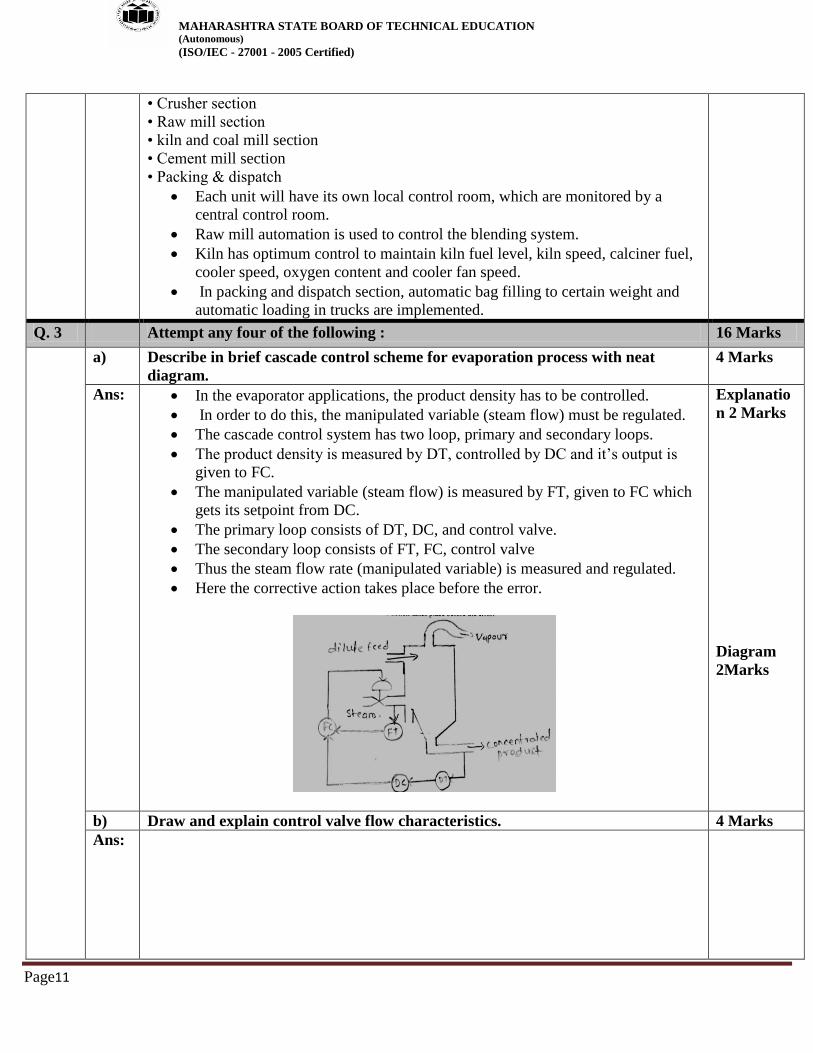
Ans: In the evaporator applications, the product density has to be controlled.
In order to do this, the manipulated variable (steam flow) must be regulated.
The cascade control system has two loop, primary and secondary loops.
The product density is measured by DT, controlled by DC and it’s output is
given to FC.
The manipulated variable (steam flow) is measured by FT, given to FC which
gets its setpoint from DC.
The primary loop consists of DT, DC, and control valve.
The secondary loop consists of FT, FC, control valve
Thus the steam flow rate (manipulated variable) is measured and regulated.
Here the corrective action takes place before the error.
Explanatio
n 2 Marks
Diagram
2Marks
b) Draw and explain control valve flow characteristics. 4 Marks
Ans:

MAHARASHTRA STATE BOARD OF TECHNICAL EDUCATION (Autonomous)
(ISO/IEC - 27001 - 2005 Certified)
Page12
Quick Opening:
This type of valve is used for full ON / OFF control operation. The valve
characteristic shows that relatively small motion of valve stem results in
maximum possible flow rate through the valve. It is used when maximum valve
capacity must be obtained quickly.
2. Linear –Here flow rate changes linearly with valve travel or stem position
𝑄
𝑄𝑚𝑎𝑥=
𝑆
𝑆𝑚𝑎𝑥
𝑆 is the stem position, 𝑄 is the flow rate
3. Equal percentage - this type of valve does not shut off the flow completely in its
limit of stem travel. Thus 𝑄𝑚𝑖𝑛 represents the minimum flow when stem is at one
limit of its travel. 𝑄𝑚𝑎𝑥is the maximum flow rate. For this valve,
Rangeability R = 𝑄𝑚𝑎𝑥
𝑄𝑚𝑖𝑛
The equal percentage curve shows that the increase in flow rate for a given
change in valve opening depends on the extent to which the valve is already
open.
This curve is exponential and is represented by
𝑄 = 𝑄𝑚𝑖𝑛𝑅𝑆 𝑆𝑚𝑎𝑥⁄
Diagram
2Marks
Brief
Explanatio
n 2 Marks
c) Compare feed forward control system with feedback control. (Any four pts.)
4 Marks
Ans:
No Feed forward Feedback
1 Acts before the effect of a
disturbance is felt by the system,
thus acts in anticipatory manner
Waits until the disturbance
affects the system, thus acts in
compensatory manner.
2 Good for slow system Not satisfactory for slow processes
Any 4
points, 1
Marks each

MAHARASHTRA STATE BOARD OF TECHNICAL EDUCATION (Autonomous)
(ISO/IEC - 27001 - 2005 Certified)
Page13
3 Does not introduce instability in the
closed loop response.
Create instability in the closed loop
response
4 Requires identification of all
possible disturbances and their
direct measurement.
Does not require identification and
measurement of any disturbances
5 Sensitive to modelling errors Insensitive to modelling errors
6 Sensitive to process parameter
variations
Insensitive to parameter changes
7 Block diagram:
Block diagram:
d) Explain control net communication method. 4 Marks
Ans: ControlNet is an open industrial control network protocol for real-time
industrial automation applications. ControlNet is a member of the CIP
(Common Industrial Protocol) network family. ControlNet has good real-time
capabilities providing high-speed deterministic transmission for time critical
I/O data and messaging data. ControlNet is highly deterministic (the ability to
reliably predict when data will be delivered) and repeatable (ensures that
transmit times are constant and unaffected by devices connecting to, or
leaving, the network) and thus meets critical requirements for synchronized
and coordinated real-time motion control applications.
ControlNet was developed by Rockwell Automation and today, it is managed
by the ControlNet International User organization. ControlNet products are
certified by the ControlNet International user organization, guaranteeing
worldwide compatibility It has the built-in support for fully redundant
cablesand communication on ControlNet can be strictly scheduled and highly
deterministic. These are its features.
ControlNet is standardized in the European standard series EN 50170. It uses
coax cables and a transmission speed of 5 Mbit/s. The Media Access method
allows multiple controllers to control I/O on the same wire.
4Marks
e) Draw and explain the construction of globe valve. 4 Marks
Ans: A globe valve is a type of valve used for regulating flow in a pipeline. It
consists of a movable disk-type element and a stationary ring seat in a
spherical body.
Explanatio
n 2
Marks

MAHARASHTRA STATE BOARD OF TECHNICAL EDUCATION (Autonomous)
(ISO/IEC - 27001 - 2005 Certified)
Page14
Globe valves are named for their spherical body shape in which the two halves
of the body being separated by an internal baffle.
This has a seat onto which a movable plug can be screwed in to close (or shut)
the valve. The plug is also called a disc. The plug is connected to a stem.
Stem is operated by screw action using a hand wheel in manual valves.
Automated globe valves use stems which are opened and closed by
an actuator assembly.
OR
Diagram
2Marks
with
labeling OR

MAHARASHTRA STATE BOARD OF TECHNICAL EDUCATION (Autonomous)
(ISO/IEC - 27001 - 2005 Certified)
Page15
Q. 4 A) Attempt any threeof the following : 12 Marks
a) Draw the block diagram of process control system. Explain it. 4 Marks
Ans: Block diagram:
The elements of a process control system are
1) Process
2) Measurement &feedback
3) Error detector
4) Controller
5) Final Control Element
Controller is the brain of the control system that takes decision to maintain the process
variable to its desired value. Mostly the summing point is an integral part of the
controller. The error detector outputs an error signal (e = r - b) to the controller, from
the reference input(r) and set point (b). Final control element is designed to take action
for implementing the decision taken by the controller. Transducer measures and
converts non electrical parameter into electrical parameter required for the error
detector.
The controlled variable is denoted by c, and the measured value by b. the controlled
variable set point is marked r. The error detector is a subtracting or summing point that
gives an error signal, e= 𝑟 ± 𝑏. The controller uses the error input to determine the
output signal p. This has been given to the control element. The control element
operates on the process by changing the value of the controlling variable u.
Diagram:2
M
Explanatio
n:2M
b) Explain working of butterfly valve with neat diagram. 4 Marks
Ans:
(OR other suitable diagram)

MAHARASHTRA STATE BOARD OF TECHNICAL EDUCATION (Autonomous)
(ISO/IEC - 27001 - 2005 Certified)
Page16
In this valve, the plug is in the form of a disc. The "butterfly" is the metal disc
mounted on a rod. The disc is positioned in the center of the pipe.A rod
connected to an actuator on the outside of the valve is passing through the disc.
Rotating the actuator turns the disc either parallel or perpendicular to the flow.
The disc is always present within the flow, therefore a pressure drop is always
induced in the flow, regardless of valve position.
A butterfly valve is from a family of valves called quarter-turn valves. In
operation, the valve is fully open or closed when the disc is rotated a quarter
turn. When the valve is closed, the disc is turned so that it completely blocks off
the passageway. When the valve is fully open, the disc is rotated a quarter turn
for the passage of the fluid.
Butterfly valves are less costly and lighter in weight, therefore less support is
required. It is used for isolating or regulating flow.
Diagram:2
M
Explanatio
n:2M
c) Enlist types of drying processes. Describe any one with neat diagram. 4 Marks
Ans: Types :- 1) Fluid- Bed Dryer
2) Spray Dryer
3) Direct Fired Rotating Kiln Dryer
4) Double Drum Dryer
OR
1) Adiabatic and Non-adiabatic Drying
2) Continuous and Batch Drying Continuous Fluid –Bed Dryer
Continuous Fluid–Bed Dryer: The continuous fluid-bed dryer shown in the following
figure. It uses a temperature controller on the air leaving the bed to manipulate the flow
of steam to the air heater. A second controller maintains bed density by holding a
constant differential pressure across it. Hot air is passed up through the perforated plate,
which comes in contact with the falling solid which is to be dried. The dried material is
discharged through the side-arm.In this dryer, rapid circulation of the solids means that
the average moisture content in the bed is approximately the same as that of the product
being discharged..As a consequence, the rate of drying is essentially that of the product.
An increase in either feed rate or moisture will lower the outlet-air temperature, causing
the controller to increase steam flow to return it to set point. However, the addition of
more heat to the air also raises its wet-bulb temperature, thereby raising the level of
moisture in the product. Therefore, this system works only on temperature and is not
sensitive to humidity.
Classificati
on -1M
Diagram-
3M
Descriptio
n-2M

MAHARASHTRA STATE BOARD OF TECHNICAL EDUCATION (Autonomous)
(ISO/IEC - 27001 - 2005 Certified)
Page17
OR
Drum Dryers:
The drum dryer is made up of a large, rotating cylindrical tube, usually supported by
concrete columns or steel beams. The dryer slopes slightly so that the discharge end is
lower than the material feed end in order to convey the material through the dryer under
gravity. Material to be dried enters the dryer, and as the dryer rotates, the material is
lifted up by a series of internal fins lining the inner wall of the dryer. When the material
gets high enough to roll back off the fins, it falls back down to the bottom of the dryer,
passing through the hot gas stream as it falls.
(Any other type with relevant diagram may also be considered)

MAHARASHTRA STATE BOARD OF TECHNICAL EDUCATION (Autonomous)
(ISO/IEC - 27001 - 2005 Certified)
Page18
d) Write the purpose of process flow sheet. 4 Marks
Ans: Process flow diagram:A process flow diagram (PFD) is a diagram commonly used in
chemical and process engineering to indicate the general flow of plant processes and
equipment. The PFD displays the relationship between major equipment of a plant
facility and does not show minor details such as piping details and designations.
Another commonly used term for a PFD is a flowsheet.
Process flow diagrams of a single unit process will include the following:
Process piping
Major equipment items
Control valves and other major valves
Connections with other systems
Major bypass and recirculation streams
Operational data (temperature, pressure, mass flow rate, density, etc.), often by
stream references to a mass balance.
Process stream names
4M
B) Attempt any one of the following : 6 Marks
a) Explain control valve selection and sizing. 6 Marks
Ans: Selection criteria for control Valve:
1. Body pressure rating: It must be as per the ANSI pressure classes.
2. Temperature considerations: It includes strength of body materials as well as
relative thermal expansion of various paths.
3. Material selection: Body materials are to be decided depending on temperature
range and erosive qualities of fluid.
4. Flow characteristics: Characteristics may have strong influence on stability of
process. Accordingly, choice may be quick opening, linear or equal percentage.
5. Rangeability: Wide rangeability may be required according to the process load
change.
6. Pressure drop: Maximum pressure drop a valve can tolerate at fully shut off and
partly open or fully open.
7. Cost Vs capacity: For larger lines, over size valves are required and cost increases.
Control valve sizing is done based on the valve coefficient.
Valve flow coefficient 𝐶𝑣is defined as the number of U.S gallons of water per
minute that flow through the fully open valve with a pressure differential of 1
psi.
It is the sizing factor for the valve.
𝐶𝑣is the correction factor to the equation 𝑄 = 𝐾√∆𝑝 because of the non ideal
characteristic of the material that flow. The correction factor allows the
selection of proper size of the control valve for the suitable rate of flow for the
given application.
𝑄 = 𝐶𝑣√∆𝑝
𝑆𝐺𝑆𝐺=specific gravity of the liquid
1 UK gallon= 1.2 US gallon
1 gallon= 4.55 litres
Selection
criteria-3M
Sizing
estimation:
3M
Sizing
definition
and
equation-
2M,
Table (1M)

MAHARASHTRA STATE BOARD OF TECHNICAL EDUCATION (Autonomous)
(ISO/IEC - 27001 - 2005 Certified)
Page19
Valve sizing table:
Valve size (inches) 𝐶𝑣
1/4 0.3
1/2 3
1 14
1 1
2 35
2 55
3 108
4 174
6 400
8 725
b) Draw the architecture of MOD—BUS and state the function of each block. 6 Marks
Ans: MOD-BUS architecture:

MAHARASHTRA STATE BOARD OF TECHNICAL EDUCATION (Autonomous)
(ISO/IEC - 27001 - 2005 Certified)
Page20
MODBUS Protocol is a messaging structure developed by Modicon in 1979, used to
establish master-slave/client-server communication between intelligent devices.
MODBUS is an application layer messaging protocol, positioned at level 7 of the OSI
model,that provides client/server communication between devices connected on
different types of buses or networks.
Communication Application Layer
A MODBUS device may provide a client and/or a server MODBUS interface.
A MODBUS backend interface can be provided allowing indirectly the access
to user application objects. Four areas can compose this interface: input discrete,
output discrete (coils), input registers and output registers.
TCP Management layer
One of the main functions of the messaging service is to manage communication
establishment and ending and to manage the data flow on established TCP
connections.
TCP layer parameterization
Some parameters of the TCP/IP stack can be adjusted to adapt its behaviorlike
the data flow control, the address management and the connection management
to the product or system constraints. Generally the BSD socket interface is used
to manage the TCP connections.
Connection Management
A communication between a client and server MODBUS Module requires the
use of a TCP connection management module. Two possibilities are proposed
for the connection management. Either the user application itself manages TCP
Diagram:3
M
Explanatio
n:3M

MAHARASHTRA STATE BOARD OF TECHNICAL EDUCATION (Autonomous)
(ISO/IEC - 27001 - 2005 Certified)
Page21
connections or the connection management is totally done by this module and
therefore it is transparent for the user application.
Access Control Module
In certain critical contexts, accessibility to internal data of devices must be
forbidden for undesirable hosts. That’s why a security mode is needed and
security process may be implemented if required.
TCP/IP Stack layer
The TCP/IP stack can be parameterized in order to adapt the data flow control,
the address management and the connection management to different
constraints specific to a product or to a system. Generally the BSD socket
interface is used to manage the TCP connections.
Resource management and Data flow control
In order to equilibrate inbound and outbound messaging data flow between the
MODBUS client and the server, data flow control mechanism is provided in all
layers of MODBUS messaging stack. The resource management and flow
control module is first based on TCP internal flow control added with some data
flow control in the data link layer and also in the user application level.
OR
Typical MOD Bus Architecture
Modbus is transmitted over serial lines between devices. The Mod bus protocol
exchanges data in a Master-Slave relationship. Each Slave has a unique address
and the data are identified by their location in the slave address register The
simplest setup would be a single serial cable connecting the serial ports on two
devices, a Master and a Slave.
The data is sent as series of ones and zeroes called bits. Each bit is sent as a
voltage. Zeroes are sent as positive voltages and a ones as negative. The bits are
sent very quickly. A typical transmission speed is 9600 baud (bits per second).
Certain characteristics of the MOD Bus Protocol are fixed such as frame
format, frame sequence, handling of communication errors, exception
conditions and functions performed. Other characteristics are user selectable
such as transmission medium, baud rate, character parity, no. of stop bits and
transmission modes (ASCII or RTU). The contents of the data are also selectable
e.g. strings, integers, floating point numbers etc.
Only the master can initiate a transaction. A query and response may involve

MAHARASHTRA STATE BOARD OF TECHNICAL EDUCATION (Autonomous)
(ISO/IEC - 27001 - 2005 Certified)
Page22
only a single slave or it may be in the form of a broadcast in which case slaves
do not answer. The query is contained in a frame that includes the address of the
intended receiver, what this slave is to do, data needed to perform the action and
a means of checking for errors. The slave checks whether errors have occurred
and performs the desired action. After the action is performed , the slave builds
the response and returns to the master. The master can send another message to
any slave as soon as it receives a valid response or after user selectable time
interval
The data can be exchanged in two transmission modes: ASCII and RTU. The
major difference between the two being the the type of error check performed
on the message and the number of characters used. Modbus offers several read,
write and test functions, each identified by a code number. They are designed
as control commands sensors, actuators, e.g coils, inputs, input registers,
holding or output registers, diagnosis and test reports, programs, polling control
and reset. For MODBUS TCP the serial frame is simply inserted into the
Ethernet data frame.
Q.5 Attempt any two of the following : 16 Marks
a) Describe the working of split range control system with example. 8 Marks
Ans: This type of control is used, where there are several manipulated variables, and
single output variable.
The coordination among different manipulated variables is carried out by
using Split Range Control.
Output of the controller is split and sent to two or more FCEs.
The splitter defines how each FCE is sequenced as the controller output
changes from 0 to 100%.
Example:
Explanatio
n 3 M
Diagram
for
example: 2
M,

MAHARASHTRA STATE BOARD OF TECHNICAL EDUCATION (Autonomous)
(ISO/IEC - 27001 - 2005 Certified)
Page23
In the above example, the steam discharges from several boilers are combined
at a steam header.
Overall steam pressure at the header is to be maintained constant through a
pressure control loop.
The command from the pressure controller is used for controlling
simultaneously the steam flow rates from the boilers in parallel.
There is a single output variable (steam header pressure) while there are a
number of manipulating variables (discharge from different boiler)
Thus the output of the controller is split and sent to two or more FCEs
Explanatio
n 3M
b) State the role of instrumentation engineer in project engineering. 8 Marks
Ans: Designing and developing new control systems
Testing, maintaining and modifying existing systems
Analyzing data and presenting findings in written reports
Managing operations
Working collaboratively with design engineers, operation engineers,
purchasers and other internal staff
Liaising with clients, suppliers, contractors and relevant authorities (e.g. The
nuclear decommissioning authority)
Project management within cost and time constrained environments
Understanding and ensuring compliance with relevant health and safety
regulations and quality standards
Providing advice and consultancy support
Purchasing equipment
Writing computer software and test procedures
Developing new business proposals
Any 8, 1M
each
c) Draw the architecture of DCS system. State functions of all components in it. 8 Marks
Ans:

MAHARASHTRA STATE BOARD OF TECHNICAL EDUCATION (Autonomous)
(ISO/IEC - 27001 - 2005 Certified)
Page24
OR
Diagram
4M

MAHARASHTRA STATE BOARD OF TECHNICAL EDUCATION (Autonomous)
(ISO/IEC - 27001 - 2005 Certified)
Page25
1. Input-output module:-
All these modules are mounted in a single or multirack system connected on
common communication highway. I/O modules scan and digitize the process in
simple logic. It provides the main interface between DCS and process being
controlled. They convert the information provided by process instruments into
digital form. They also provide signal filtering.
2. Local I/O bus:-
It provides bridge between I/O and controller module and is restricted in terms of
geographical area and data loading. It operates at slower speed than the plant
wide data highway communication.
3. Controller module:-
It is the brain of the DCS. It updates field datafrom I/O module and performs
control calculation and logic to make the process changes. It also consists of
memory, registers and buses, CPU, ROM and RAM. Hence it is microprocessor
based device.
4. Communication module:-
It provides communication between data highway and other modules such as
controller module and user interfaces. Communication module manages the
Explanatio
n 4 M

MAHARASHTRA STATE BOARD OF TECHNICAL EDUCATION (Autonomous)
(ISO/IEC - 27001 - 2005 Certified)
Page26
flow of information between the data highway, controller module and user
interface.
5. Data highway:-
The data highway is the communication device that allows distribution of the
controlling function throughout a large plant area. It is the digital data link
that connects the multifunction controllers with the central operator stations.
Data highway is microprocessor based module through which the messages
and files are transferred.The medium can be coaxial cable or the fiber glass
cable.
6. User interface:-
It provides the interface between user and process. It can either operator interface
or engineer interface.
Operator Station:- it performs:
1) From operator station, operator can view entire plant/process and
can control the process.
2) Controlling the complete process (regulatory and supervisory
control);allows configuration of all inputs
3) Alarm display setting.
Engineer Station:- it performs following functions:
1) system design and generation of system loop diagram
2) documentation
3) programming
4) system maintenance
Q.6 Attempt any four of the following : 16 Marks
a) Explain the role of DCS in thermal power industry. 4 Marks
Ans:
OR
Diagram 2
M

MAHARASHTRA STATE BOARD OF TECHNICAL EDUCATION (Autonomous)
(ISO/IEC - 27001 - 2005 Certified)
Page27
Explanation:
A distributed control system (DCS) is a control system for a process where the
control elements or modules are distributed throughout the system. It is a
multitasking operating system which is user friendly with a data management
system. The DCS has capacity for processing large number of I/O points.
It has a modular system development capacity (expandable) which is easy to
use. It has data highway, communication capability and data transmission
between separate unites of the data highway which provide very wide band
communication.
OR
Power plant involves the following activities:
1. Raw Material Transportation and Processing
2. Boiler Combustion (Pulverization of Coal / CFB)
3. Turbine (Steam Turbine and Heat Recovery) Monitoring and Control
4. Generator and Plant Electrical System Monitoring and Control
5. Waste and Exhaust Treatment.
Following major variables are measured and controlled:
Input variables:
Fuel flow rate, Combustion air, Feed water flow, Steam flow / pressure
Control variables:
Drum level, Steam pressure, Furnace draft, Waste gases composition.
Above variables are continuously monitored and controlled byDCS and indicated
using different DCS displays such as Graphic display, Group display, Trend display,
Alarm display, Log and repeat display etc.
Explanatio
n 2 M
b) Find the proper valve size in inches and centimeter for pumping the liquid. Flow
rate of 700 gal/min with maximum pressure difference of 65 PSi and liquid
specific gravity is 1.3. Findvalve size.
4 Marks

MAHARASHTRA STATE BOARD OF TECHNICAL EDUCATION (Autonomous)
(ISO/IEC - 27001 - 2005 Certified)
Page28
Ans: Data given:
Q = 700 gal/min, ∆𝑃 = 65 𝑝𝑠𝑖 G=1.3
Flow rate 𝑄 = 𝐶𝑉√∆𝑃
𝐺
Therefore𝐶𝑉 = 𝑄√𝐺
∆𝑃 = 700 √
1.3
65 = 700× 0.141 = 98.7
The required valve size for 𝐶𝑉 = 98.7 is 3 inches
4 M
c) Compare Batch and Continuous process (4 points). 4 Marks
Ans:
No. Batch process Continuous process
1 In this, material is fed to equipment
batch wise and then it is processed
to obtain finished products.
In this, material is fed continuously in
equipment and is immediately processed
and finished product is obtained
continuously.
2 Raw materials are fed before the
start of the operation
Raw materials are fed continuously
throughout the process
3 During process operation neither
addition of material nor removal of
finished product from unit occurs.
During process operation therate of
process output is matched with input
material.
4 Preferred in small scale production. Preferred in large scale production.
5 Simple Control system is required. More complex control system is required.
6 Load change effects are less. Load change effects are more
7 Series operation Parallel operation
8 More time is needed for operation Less time is needed for operation
9 Large installation, therefore cost
is more
Relatively small installation, therefore
cost is less
Any 4,
1M each
d) Draw block diagram of automatic control system. Explain each block. 4 Marks
Ans: Block Diagram of automatic control system:
Note: any other relevant diagram can also be considered.
02 M
diagram

MAHARASHTRA STATE BOARD OF TECHNICAL EDUCATION (Autonomous)
(ISO/IEC - 27001 - 2005 Certified)
Page29
Explanation:
1) Process:A process can consist of a complex assembly of phenomena that relate to some
manufacturing sequence. Many variables may be involved in such a process, and it may
be desirable to control all these variables at the same time. There are singlevariable
processes, in which only one variable is to be controlled, as well as multivariable
processes, in which many variables, perhaps interrelated, may require regulation. The
process is often also called the plant.
2) Measurement: a measurement refers to the conversion of the variable into some
corresponding analog of the variable, such as a pneumatic pressure, an electrical
voltage or current, or a digitally encoded signal. A sensor is a device that performs the
initial measurement and energy conversion of a variable into analogous digital,
electrical, or pneumatic information. Further transformation or signal conditioning may
be required to complete the measurement function. The result of the measurement is a
representation of the variable value in some form required by the other elements in the
process-control operation.
3) Controller:The next step in the process-control sequence is to examine the error and
determine what action, if any, should be taken. This part of the control system has many
names, such as compensator or filter, but controller is the most common.
4) Final Control element:The final element in the process-control operation is the device
that exerts a direct influence on the process; that is, it provides those required changes
in the controlled variable to bring it to the setpoint. This element accepts an input from
the controller, which is then transformed into some proportional operation performed
on the process.
02 M
explanation
e) Identify the elements of level. Explain cavitation and flashing.
4 Marks
Ans: 1- Level gauge (LG)
2- Level transmitter (LT)
3- Level controller (LC)
Cavitation is the formation and subsequent collapse of vapour cavities or gas
"bubbles" or "voids" in a flowing liquid in a region where the local static pressure of
the liquid falls below its vapour pressure.
Flashing is the formation of vapour cavities or gas "bubbles" or "voids" in a flowing
liquid in a region where the local static pressure of the liquid falls below its vapour
pressure andthevapour phase continues downstream because the downstream pressure
remains at or below the vapour pressure of the liquid.
2M
Definition
2 M


![Smart Valve Positioner 300 Series › products › factory › download › ... · “Valve system,” in this document, configure the valve action correctly. [4] If linearity characteristic](https://static.fdocuments.net/doc/165x107/5f192e6f38516e334e0f8ec2/smart-valve-positioner-300-series-a-products-a-factory-a-download-a-.jpg)


