MODEL AIO 2 ALL IN ONE WEATHER SENSOR
28
MODEL AIO 2 ALL IN ONE WEATHER SENSOR OPERATION MANUAL Document No. AIO 2-9800 Rev. F Met One Instruments, Inc Corporate Sales & Service: 1600 NW Washington Blvd. Grants Pass, OR 97526 Tel (541) 471-7111 Fax (541) 471-7116 www.metone.com - [email protected]
Transcript of MODEL AIO 2 ALL IN ONE WEATHER SENSOR

MODEL AIO 2 ALL IN ONE WEATHER SENSOR
OPERATION MANUAL
Document No. AIO 2-9800 Rev. F
Met One Instruments, Inc Corporate Sales & Service: 1600 NW Washington Blvd. Grants Pass, OR 97526 Tel (541) 471-7111 Fax (541) 471-7116 www.metone.com - [email protected]

AIO 2-9800 Rev F AIO 2 All In One Weather Sensor Operation Manual 1 of 27

AIO 2-9800 Rev F AIO 2 All In One Weather Sensor Operation Manual 2 of 27
Copyright Notice
AIO 2 Weather Sensor Manual © Copyright 2018 Met One Instruments, Inc. All Rights Reserved Worldwide. No part of this publication may be reproduced, transmitted, transcribed, stored in a retrieval system, or translated into any other language in any form by any means without the express written permission of Met One Instruments, Inc.
Technical Support
This manual is structured by customer feedback to provide the required information for setup, operation, testing, maintaining, and troubleshooting your AIO 2 Weather Sensor. Should you still require support after consulting your printed documentation, we encourage you to contact one of our expert Technical Service representatives during normal business hours of 7:00 a.m. to 4:00 p.m. Pacific Time, Monday through Friday. In addition, technical information and service bulletins are often posted on our website. Please contact us and obtain a Return Authorization (RA) number before sending any equipment back to the factory. This allows us to track and schedule service work and to expedite customer service. Please have your instrument serial number available when contacting the manufacturer.
Voice: (541) 471-7111
Fax: (541) 471-7116
E-Mail: [email protected]
Mail: Technical Services Department Met One Instruments, Inc. 1600 NW Washington Blvd Grants Pass, OR 97526

AIO 2-9800 Rev F AIO 2 All In One Weather Sensor Operation Manual 3 of 27
Safety Notice The contents of this manual have been checked against the hardware and software described herein. Since deviations cannot be prevented entirely, we cannot guarantee full agreement. However, the information in this manual is reviewed regularly and any necessary corrections are included in subsequent editions. Faultless and safe operation of the product presupposes proper transportation, storage, and installation as well as careful operation and maintenance. The seller of this equipment cannot foresee all possible modes of operation in which the user may attempt to utilize this instrumentation. The user assumes all liability associated with the use of this instrumentation. The seller further disclaims any responsibility for consequential damages.
Electrical & Safety Conformity The manufacturer certifies that this product operates in compliance with the following standards and regulations: FDA/CDRH This product is tested and complies with 21 CFR, Subchapter J, of the Health and Safety Act of 1968 US 21 CFR 1040.10

AIO 2-9800 Rev F AIO 2 All In One Weather Sensor Operation Manual 4 of 27
Table of Contents1. Introduction & Overview – AIO 2 All In One Weather Sensor ......................................................... 6
1.1. Overview ...................................................................................................................................... 6
2. Specifications ....................................................................................................................................... 7
3. Unpacking & Installation ..................................................................................................................... 8
3.1. Unpacking ..................................................................................................................................... 8
3.2. Deployment ................................................................................................................................... 9
3.2.1. Tripod / Pipe top Installation: ................................................................................................. 9
3.2.2. Universal Mounting Arm Installation: ................................................................................. 12
3.3. Input / Output Connections ....................................................................................................... 13
3.4. Operational Checkout ................................................................................................................ 14
3.5. Maintenance ................................................................................................................................ 14
3.6. Setting Magnetic Declination .................................................................................................... 14
4. User Selectable Options ................................................................................................................... 15
5. User Interface ..................................................................................................................................... 16
6. Standard Configuration ..................................................................................................................... 18
7. Appendix A ......................................................................................................................................... 19
7.1. Terminal Mode and SDI Commands ......................................................................................... 19
7.1.1. H,h,? – Display Help Menu ................................................................................................... 19
7.1.2. BV – Battery Voltage Printout Toggle On/Off ..................................................................... 19
7.1.3. CV – Compass Measurement Printout Toggle On/Off ....................................................... 20
7.1.4. ID – View / Set Instrument ID ................................................................................................ 20
7.1.5. MA – View / Set Modbus Address ........................................................................................ 20
7.1.6. ME – Metric or English Units ................................................................................................ 20
7.1.7. SU –Wind Speed Units .......................................................................................................... 21
7.1.8. TU –Temperature Units ......................................................................................................... 21
7.1.9. PU –Barometric Pressure Units ........................................................................................... 21
7.1.10. RU –Rain Units ...................................................................................................................... 21

AIO 2-9800 Rev F AIO 2 All In One Weather Sensor Operation Manual 5 of 27
7.1.11. MD –Magnetic Declination .................................................................................................... 22
7.1.12. OI –Output Interval ................................................................................................................ 22
7.1.13. ST – Serial Trigger................................................................................................................. 23
7.1.14. SA – SDI-12 Address ............................................................................................................. 23
7.1.15. SC – Solar Calibration .......................................................................................................... 23
7.1.16. RT – Output Record Type ..................................................................................................... 23
7.1.17. RV – Software Version Number ........................................................................................... 23
7.2. SDI-12 Commands ...................................................................................................................... 24
8. Modbus ............................................................................................................................................... 26
8.1. Modbus operation: ..................................................................................................................... 26
3X Registers ...................................................................................................................................................... 26
4X Registers ...................................................................................................................................................... 26
9. Appendix B ......................................................................................................................................... 27
9.1. Theory of Operation ................................................................................................................... 27

AIO 2-9800 Rev F AIO 2 All In One Weather Sensor Operation Manual 6 of 27
1. Introduction & Overview – AIO 2 All In One Weather Sensor
1.1. Overview
The AIO 2 Weather Sensor provides measurements of wind speed, wind direction, ambient air temperature, relative humidity, and barometric pressure in a single, compact, rugged unit. It integrates a folded-path, low-power sonic anemometer with a precision thermistor temperature sensor, fast-response capacitive relative humidity sensor, and a state-of-the-art barometric pressure sensor. It also includes an internal flux-gate compass that allows for automatic alignment of wind direction to magnetic north, regardless of the sensor’s orientation. The small footprint and power efficiency of the AIO 2 make it ideal for remote regions, urban environments, air quality networks, construction/remediation sites, and other network applications. The unit can be used in permanent (cooperative weather networks, schools, public information dissemination) or temporary (emergency response, audit, research program support) installations. Designed for maximum portability and utility, the AIO 2 is well suited for rapid deployment and use by one person under all conditions. The unit may be mounted on a tower, tripod or vehicle mast. Data output is a serial, digital message that can be interfaced to most data logging systems. The AIO 2 even has the capability to connect an external contact closure rain gauge (such as the Met One 360 or 370) and/or solar radiation sensor (such as the Met One 10718). If these inputs are present, their measurements are then integrated into the AIO 2 serial data output.

AIO 2-9800 Rev F AIO 2 All In One Weather Sensor Operation Manual 7 of 27
2. Specifications
PARAMETER SPECIFICATION
Wind Speed Operating Range 0 to 75 m/s (0 to 168 mph)
Wind Speed Calibrated Range 0 to 60 m/s (0 to 134 mph)
Wind Speed Accuracy ±0.5 m/s or 5% of reading (whichever is greater)
Wind Speed Resolution 0.1 m/s
Wind Direction Range 0 to 360 degrees
Wind Direction Accuracy ±5° (including Compass)
Wind Direction Resolution 1.0°
Alignment Compass Accuracy ±2°
Alignment Compass Resolution 1°
Temperature Range -40 to +60 °C (-40 to +140 °F)
Temperature Accuracy ±0.2 °C from 0 to 60 °C, ±0.5 °C from -40 to 0 °C
Temperature Resolution 0.1 °C
Relative Humidity Range 0 to 100%
Relative Humidity Accuracy ±3% 25 °C
Relative Humidity Resolution 1.0%
Barometric Pressure Range 600 to 1100 hPa
Barometric Pressure Accuracy ±0.5 hPa 25 °C
Barometric Pressure Resolution 0.1 hPa
External Rain Gauge Input Resolution 0.25mm or 0.01”, user selectable
External Solar Radiation Sensor Input Measured in W/m2
Measurement Rate Output 1 Hz
Signal Output Type RS-232, RS-485, and SDI-12
Operating Temperature -40 to +60 °C (-40 to +140 °F)
Operating Relative Humidity 0 to 100%
Dimensions 4.5 inches diameter, 11 inches height
Shipping Weight 6 pounds (including packaging)

AIO 2-9800 Rev F AIO 2 All In One Weather Sensor Operation Manual 8 of 27
3. Unpacking & Installation
3.1. Unpacking
Any damages incurred to the equipment during shipping are the responsibility of the carrier. If any damage to the shipment is noticed before unpacking, a claim must be filed with the commercial carrier immediately. You should follow any special unpacking instructions provided by the carrier as you then carefully remove all items from the containers and inspect each component. It is recommended to document and photograph all damaged packages and items before, during, and after unpacking them. Unpack the AIO 2 and accessories and make a visual inspection of the contents; contact your supplier if anything is missing. The AIO 2 Weather Sensor ships with the following items:
AIO 2 All In One Weather Sensor.
Calibration certificate.
Operation manual (this document). Optional Accessories that may be purchased include:
10523 ¾” IPS pipe vertical mounting adaptor
10106 Universal mounting arm
10600 Interface station – provides wiring terminals, 12VDC power, USB and DB9 serial connections.
WeatherView Software
USB Driver CD
Comet Terminal Software CD The required 10624 signal cable is sold separately. It is custom built to the desired length. Contact Met One Instruments (see the Technical Support section at the beginning of this manual) to arrange for any replacement items needed. Please keep the carton(s) and associated packing materials for reuse.

AIO 2-9800 Rev F AIO 2 All In One Weather Sensor Operation Manual 9 of 27
3.2. Deployment
3.2.1. Tripod / Pipe top Installation:
The AIO 2 can be quickly and easily deployed on top of a Met One 905 tripod or any other vertical ¾” IPS pipe using the optional 10523 vertical mount.
AIO 2-9800 Rev F AIO 2 All In One Weather Sensor Operation Manual 10 of 27
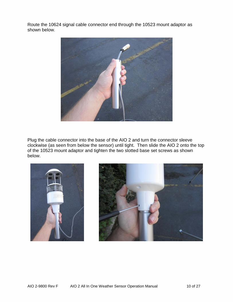
Route the 10624 signal cable connector end through the 10523 mount adaptor as shown below.
Plug the cable connector into the base of the AIO 2 and turn the connector sleeve clockwise (as seen from below the sensor) until tight. Then slide the AIO 2 onto the top of the 10523 mount adaptor and tighten the two slotted base set screws as shown below.

AIO 2-9800 Rev F AIO 2 All In One Weather Sensor Operation Manual 11 of 27
Position the cable in the slot on the side of the mount and then slide the assembly onto the tripod mast or pipe. Tighten the 2 set screws on the 10523 mount to affix it to the tripod/pipe.
The AIO 2 includes an internal alignment compass so the adaptor and AIO 2 sensor can face any direction and still correctly read wind direction (as referenced to Magnetic North). The MD command can be used to set a magnetic declination to reference the wind direction reading to True North. See section 3.6 for more details about setting the magnetic declination. Run the signal cable from the mount to the data collection device being used (such as a data logger or computer) following the wiring connections listed in section 3.3.
AIO 2-9800 Rev F AIO 2 All In One Weather Sensor Operation Manual 12 of 27
3.2.2. Universal Mounting Arm Installation:
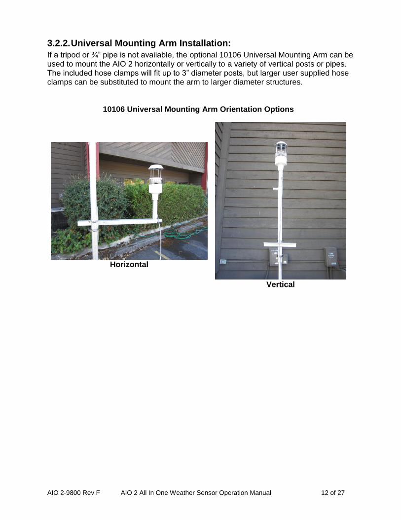
If a tripod or ¾” pipe is not available, the optional 10106 Universal Mounting Arm can be used to mount the AIO 2 horizontally or vertically to a variety of vertical posts or pipes. The included hose clamps will fit up to 3” diameter posts, but larger user supplied hose clamps can be substituted to mount the arm to larger diameter structures.
10106 Universal Mounting Arm Orientation Options
Horizontal
Vertical

AIO 2-9800 Rev F AIO 2 All In One Weather Sensor Operation Manual 13 of 27
3.3. Input / Output Connections
10624 Cable Wire Color Designations:
RED POWER POSITIVE (8-36VDC, 30mA nominal @ 12VDC)
BLK POWER COMMON
BLU SDI-12
GRN SIGNAL COMMON
WHT RS-232 TX
BRN RS-232 RX
YLW RS-485 +A
GRY RS-485 -B
ORN EXTERNAL RAIN GAUGE OPTION INPUT
VIO EXTERNAL SOLAR RADIATION SENSOR OPTION INPUT
WHT/BRN SHIELD (must be grounded for transient protection to function)
Warning: Do not short any of the signal or power wires to ground or to each other. Maximum Cable Length Considerations: The maximum recommended cable length depends on the communication protocol to be used: RS-232C 50FT maximum RS-485 4000FT maximum SDI-12 200FT maximum Connecting to the optional 10600 Interface Base Station The optional 10600 Interface Base Station provides:
o 12VDC power to the sensor o Convenient wiring terminal blocks for the AIO 2 sensor o Connection points for optional external Rain gauge and Solar radiation
sensors. o USB and DB9 serial port outputs for easy Computer connectivity.
See the included 10600 manual for use and connection details.

AIO 2-9800 Rev F AIO 2 All In One Weather Sensor Operation Manual 14 of 27
3.4. Operational Checkout
Connect the AIO 2 to your data logger or recording electronics. Connect power to the sensor cable per wiring diagram in section 3.3. The AIO 2 will automatically start streaming its serial output and your recording electronics should start displaying or recording measurements from the AIO 2. Verify the data seems reasonable by comparing it to data from a local weather source. If the data looks OK, the unit is in operation. If data is questionable, contact Met One Instruments, Inc. Service Department for further guidance (see the Technical Support section at the beginning of this manual).
3.5. Maintenance
The unit has no moving parts and therefore requires no periodic maintenance for wear items. It is recommended that the data be checked every 6 -12 months to be sure there has been no failure of any of the electrical components. This can be done by placing a small container (at least 12inch diameter) over the sensor to zero check the wind measurement. The ambient temperature, relative humidity, and pressure readings can be verified against collocated devices such as the Met One 083E-1-35 T/RH sensor and Met One 092 BP sensor.
3.6. Setting Magnetic Declination
The internal flux gate compass automatically corrects the wind direction in the AIO 2 to magnetic North. This means that the unit will not require directional alignment or orientation upon deployment. If it is necessary to measure wind direction referenced to True North it is important to understand and know the magnetic declination of the area in which the sensor is being operated. The declination in the AIO 2 is factory set at zero degrees. To change this, refer to the MD command instruction in section 7.1.11 for setting the Magnetic Declination.

AIO 2-9800 Rev F AIO 2 All In One Weather Sensor Operation Manual 15 of 27
4. User Selectable Options
The following User Defined Options can be set following the instructions detailed in Appendix A. BV Battery Voltage Printout Toggle On/Off CV Compass Reading Printout Toggle On/Off ID View / Set Instrument ID MA Set MODBUS Address MD Set Magnetic Declination ME Metric or English Units OI Set Output Interval PU Set Pressure Units RT Output Record Type RU Set Rain Units RV Display Firmware Version Number SA SDI Address SC Solar Option Calibration Constant ST Set Serial Trigger Address SU Set Wind Speed Units TU Set Temperature Units Q Quit Terminal Mode and Save changes

AIO 2-9800 Rev F AIO 2 All In One Weather Sensor Operation Manual 16 of 27
5. User Interface
The output of the AIO 2 is a fixed length, comma delimited, serial data stream. The serial output is factory set for 9600 baud, no parity, 8 data bits, 1 stop bit, and no flow control. The output interval default is once per second. This may be changed using the OI command (see Appendix A). The data is easily viewed and can be displayed and captured using Met One Instruments’ Comet Software or other terminal communication program. An example of the standard output format is shown below: 000.6,272,+023.6,022,0974.3,000.00,0000,12.7,U0,*02257 CR/LF Each parameter is a fixed length with leading zeros separated by a comma. The string terminates with a Carriage Return and Line Feed. Field parameters are defined as: 000.6,272,+023.6,022,0974.3,000.00,0000,12.7,U0,*02257 CR/LF WS,WD,AT,RH,BP,RN,SR,BV,CONFIG,CheckSum The wind speed, temperature, pressure and rainfall units can be changed with the SU, TU, PU, and RU terminal commands respectively. Please refer to Appendix A for more information. NOTE: the internal alignment compass reading can be added to the output string using the CV command; see Section 7.1.3 for details and an output string example. The AIO 2 output can also be configured to emulate the Legacy AIO 102780 output data format. An example of the Legacy AIO output format is shown below:
002.6, 219, +020.8, 042, 1013.2, *1787CR/LF Each parameter is a fixed length with leading zeros separated by a comma and one space. The string terminates with a Carriage Return and Line Feed. Field parameters are defined as: 002.6, 219, +020.8, 042, 1013.2, *1787 WS WD Temp RH BP Check Sum
Note: when displaying the pressure in In/Hg, there will be an extra leading zero character but the fixed length of the field will not change.
A check sum parameter will be added to the end of the message (*9999).
The check sum is the addition of all the characters from the start of the message through the first character preceding the asterisk (*). The check sum is expressed as a decimal number. This is a 16 bit sum and should not overflow past 4 digits given the number of characters in the output string.

AIO 2-9800 Rev F AIO 2 All In One Weather Sensor Operation Manual 17 of 27
Polled data mode (RS232 or RS485) The sensor can be set for polled data mode instead of continuous serial output by setting the OI command to Zero, and using the serial trigger string to request a data string. Refer to the ST terminal command in Appendix A for instructions on setting the Serial Trigger. SDI-12 Interface In addition to the above communications methods, the sensor can be polled by an SDI-12 Master Station for data. This operates completely independent of the RS232 or RS485 communications and can be used in conjunction with those methods. Data are polled using a series of SDI-12 commands. Please see appendix A for a list of supported SDI commands. The default SDI Address for the AIO 2 is zero. Please consult your data-logger manual for more information on SDI interfaces or call Met One for additional help.

AIO 2-9800 Rev F AIO 2 All In One Weather Sensor Operation Manual 18 of 27
6. Standard Configuration
Serial Interface The serial interface is fixed at 9600 Baud and configured for No Parity, 8 Data Bits and 1 Stop Bit, with no flow control. Wind Speed The Wind Speed unit choices are MPH or M/S. The default is M/S. The Speed range for M/S is 0-60. The Speed range for MPH is 0-134. Temperature The Temperature unit choices are Degrees C or Degrees F. The default is Degrees C. The range for Degrees C is -40 to +60, the range for Degrees F is -40 to +140. Pressure Pressure Range choices are In/Hg, Millibars, or mm/Hg, and the default is Millibars. The Pressure range for Millibars is 600-1100, for In/Hg is 17.72 to 32.48, and for mm/hG is 450 to 825. Precipitation Input The Precipitation resolution can be 0.25mm/tip or 0.01”/tip. 0.25mm/tip is the default. Solar Radiation Input The Solar Radiation input units are watts per square meter. The default calibration constant is 2 W/m2 per mV (1.000VDC = 2000 W/m2).
AIO 2-9800 Rev F AIO 2 All In One Weather Sensor Operation Manual 19 of 27
7. Appendix A
7.1. Terminal Mode and SDI Commands
RS232 / RS485 Terminal Mode Commands Terminal mode is activated by entering three carriage return characters within a 2 second period. Terminal mode times-out after 2 minutes of inactivity. Successful entry into Terminal Mode will return an asterisk prompt:
7.1.1. H,h,? – Display Help Menu
BV - Battery Voltage Printout Toggle On/Off CV - Compass Heading Printout Toggle On/Off ID - View / Set Instrument ID MA - Set MODBUS Address MD - Set Magnetic Declination ME - Metric or English Units OI - Set Output Interval PU - Set Pressure Units SA - SDI Address SC - Solar Calibration RT - Output Record Type ST - Set Serial Trigger Address SU - Set Speed Units TU - Set Temperature Units RV - Display Firmware Version Number RU - Set Rain Units Q - Quit command mode and save any changes
NOTE: The commands noted in this appendix will change both the RS232 and RS485 outputs. The SDI-12 output can be configured independently. See pages below for SDI-12 commands.
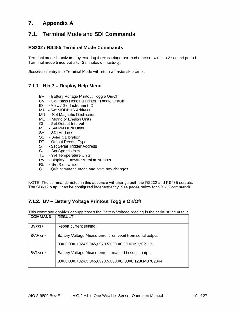
7.1.2. BV – Battery Voltage Printout Toggle On/Off
This command enables or suppresses the Battery Voltage reading in the serial string output.
COMMAND RESULT
BV<cr> Report current setting
BV0<cr> Battery Voltage Measurement removed from serial output
000.0,000,+024.5,045,0970.5,000.00,0000,M0,*02112
BV1<cr> Battery Voltage Measurement enabled in serial output
000.0,000,+024.5,045,0970.5,000.00, 0000,12.0,M0,*02344

AIO 2-9800 Rev F AIO 2 All In One Weather Sensor Operation Manual 20 of 27
7.1.3. CV – Compass Measurement Printout Toggle On/Off
This command enables or suppresses the Compass Reading in the serial string output.
COMMAND RESULT
CV<cr> Report current setting
CV0<cr> Compass Measurement removed from serial output
000.0,000,+024.5,045,0970.5,000.00, 0000,12.0,M0,*02344
CV1<cr> Compass Measurement enabled in serial output
000.0,000,+024.5,045,0970.5,000.00, 0000,12.0,240,M0,*0254
7.1.4. ID – View / Set Instrument ID
Read or Set the Instrument ID
COMMAND RESULT
ID<cr> Report the Instrument ID setting (provides help)
ID XX<cr> Set Instrument ID to number from 1 to 99
7.1.5. MA – View / Set Modbus Address
Read or Set the Modbus Address
COMMAND RESULT
MA<cr> Report the Modbus Address setting (provides help)
MA XX<cr> Set Instrument ID to number from 1 to 247. Setting this value to 0 will disable Modbus.
7.1.6. ME – Metric or English Units
This command will set all units in the the serial port’s output to Metric or English
COMMAND RESULT
ME<cr> Report Units setting
ME0<cr> Set Units to Metric (Default): WS: m/s AT: Deg C BP: mbars RN: mm
ME1<cr> Set Units to English: WS: MPH, AT: Deg F BP: inHg

AIO 2-9800 Rev F AIO 2 All In One Weather Sensor Operation Manual 21 of 27
RN: inches
7.1.7. SU –Wind Speed Units
Read or Set this serial port’s output Units for Wind Speed
COMMAND RESULT
SU<cr> Report Units setting
SU0<cr> M/S
SU1<cr> MPH
7.1.8. TU –Temperature Units
Read or Set this serial port’s output Units for Temperature
COMMAND RESULT
TU<cr> Report Units setting
TU0<cr> Fahrenheit
TU1<cr> Celsius
7.1.9. PU –Barometric Pressure Units
Read or Set this serial port’s output Units for Pressure
COMMAND RESULT
PU<cr> Report Units setting
PU0<cr> Millibars (Default)
PU1<cr> Inches of Mercury
PU2<cr> Millimeters of Mercury
7.1.10. RU –Rain Units
Read or Set this serial port’s output Units for Pressure
COMMAND RESULT
RU<cr> Report Units setting
RU0<cr> mm (Default)
RU1<cr> Inches

AIO 2-9800 Rev F AIO 2 All In One Weather Sensor Operation Manual 22 of 27
7.1.11. MD –Magnetic Declination
The flux compass in the AIO 2 sensor provides Wind Direction to MAGNETIC north. Software in the Interface allows the setting of a declination angle to correct the Wind Direction output to TRUE north. It is recommended that this procedure be done in the lab, but can be done in the field as well. Once the declination angle is set in the sensor, it is stored in non-volatile memory, and does not have to be reset each time the sensor is fielded. The declination angle must be reset only if the system is used in a different geographical location separated by many miles from the location where the declination was originally set. It is suggested that the magnetic declination be determined before performing this calibration. Visit the following web site for help in determining the correct declination for your site: www.ngdc.noaa.gov/geomag/declination.shtml Click “Compute your declination”. On the next page, enter either zip code, or select country and city, then click “Get Location” and then “Calculate”. Alternatively, you can enter longitude and latitude directly, and then click “Calculate”. Declination is reported in Degrees, Minutes and Seconds. Divide minute’s value by 60 to get decimal fraction of degrees (I.E. 50 minutes = 0.8 degrees). If the declination needs to be adjusted, please use the MD command as shown below. Read or Set the Magnetic Declination
COMMAND RESULT
MD<cr> Report Magnetic Declination setting
MDXX.X<cr> Set Declination to XX.X Degrees
Note: West declination values are entered and reported as negative values.
7.1.12. OI –Output Interval
Read or Set the Output Interval for this serial port Note: This command is not supported by SDI-12.
COMMAND RESULT
OI<cr> Report Output Interval setting
OI0<cr> For Serial Trigger (Address must be set with ST command).
OI1<cr> Sensor Output every 1 second (Default)
OI2<cr> Sensor Output every 2 seconds
OI3<cr> Sensor Output every 5 seconds
OI4<cr> Sensor Output every 15 seconds
OI5<cr> Sensor Output every 30 seconds
OI6<cr> Sensor Output every 60 seconds

AIO 2-9800 Rev F AIO 2 All In One Weather Sensor Operation Manual 23 of 27
7.1.13. ST – Serial Trigger
Read or Set the Serial Trigger character string (Poll command)
COMMAND RESULT
ST<cr> Report Serial Trigger string setting (provides help)
ST XXXXXX<cr> Set Serial Trigger
7.1.14. SA – SDI-12 Address
Read or Set the SDI-12 Address, used to poll data in SDI-12 mode.
COMMAND RESULT
SA<cr> Report SDI-12 Address string setting (provides help)
SAx<cr> Set SDI-12 Address, where ‘x’ is in the range [0-9], [A-Z] or [a-z] Case Sensitive.
7.1.15. SC – Solar Calibration
Read or Set the Solar Radiation Input Calibration Constant, units are in W/m2 per mV.
COMMAND RESULT
SC<cr> Report Solar Radiation Input Calibration Constant Default is 2 W/m2 per mV (1.000V = 2000W/m2)
SCX.XXX<cr> Set Solar Calibration Constant to x.xxx in W/m2 per mV.
7.1.16. RT – Output Record Type
Read or Set the Output Record type.
COMMAND RESULT
RT<cr> Report Output Record Type
RT1<cr> Set Output Record Type to Met Record format (default).
RT2<cr> Set Output Record Type to AIO format for compatibility with legacy AIO 102780 systems.
7.1.17. RV – Software Version Number
Report the current Software Version Number
COMMAND RESULT
RV<cr> Report current Software Version

AIO 2-9800 Rev F AIO 2 All In One Weather Sensor Operation Manual 24 of 27
7.2. SDI-12 Commands
NAME SDI-12 COMMAND
SENSOR RESPONSE
Address Query ?! a<CR><LF> Where a = address
Acknowledge Active a! a<CR><LF> Where a = address
Send Identification aI! a13METONE AIO 2 2.0.0xxxxx<CR><LF> Where a=address and xxxxx = S/N
Change Address aAb! b<CR><LF> Where b = new address
Start Measurement aM! a0009<CR><LF> Where a = address
Start Measurement with CRC aMC! a0009{crc}<CR><LF> Where a = address and {crc} = CRC
Send Data aD0! a+bbb.b+ccc.c+ddd.d+eee.e<CR><LF> Where a = address, bbb.b = wind speed, ccc.c = wind direction, ddd.d = temperature, and Send Data eee.e = relative humidity
aD1! a+ffff.f+gggg.g+hhhh+ii.ii<CR><LF> Where a = address, ffff.f = barometric pressure, gggg.g = Rain Option, hhhh = Solar Option, and
ii.ii = Power Supply Voltage
Start Concurrent Measurement
aC! a00009<CR><LF> Where a = address
Start Concurrent Measurement with CRC
aCC! a00009{crc}<CR><LF> Where a = address and {crc} = CRC
Continuous Measurements aR0! a+bbb.b+ccc.c+ddd.d+eee.e<CR><LF> Where a = address, bbb.b = wind speed, ccc.c = wind direction, ddd.d = temperature, and
eee.e = relative humidity
aR1! a+ffff.f+gggg.g+hhhh+ii.ii<CR><LF> Where a = address, ffff.f = barometric pressure, gggg.g = Rain Option, hhhh = Solar Option, and
ii.ii = Power Supply Voltage
Continuous Measurements with CRC
aRC0! a+bbb.b+ccc.c+ddd.d+eee.e{crc}<CR><LF> Where a = address, bbb.b = wind speed, ccc.c = wind direction, ddd.d = temperature, eee.e = relative humidity, and {crc} = CRC
aRC1! a+ffff.f+gggg.g+hhhh+ii.ii{crc}<CR><LF> Where a = address, ffff.f = barometric pressure, gggg.g = Rain Option, hhhh = Solar Option, and
ii.ii = Power Supply Voltage and {crc} = CRC

AIO 2-9800 Rev F AIO 2 All In One Weather Sensor Operation Manual 25 of 27
NAME SDI-12 COMMAND
SENSOR RESPONSE
Report Wind Units aXSU! aXSUb!<CR><LF> Where a = address, and b = 0 for Meters per Second (default), or
1 for Miles per Hour
Set Wind Units aXSUb aXSUb!
Report Temperature Units aXTU! aXTUd<CR><LF> Where a = address, and d = 0 for Celsius (default), or
1 for Fahrenheit
Set Temperature Units aXTUd!
Report Pressure Units aXPU! aXPUf<CR><LF> Where a = address, and f = 0 for Millibars (default), or 1 for Inches of Mercury
Set Pressure Units aXPUf!
Report Rain Units aXRU! aXRUf<CR><LF> Where a = address, and f = 0 for mm (default), or
1 for Inches
Set Rain Units aXRUf!
Report Version Number aXRV! aXVNxx.x<CR><LF> Where a = address and xx.x = firmware version

AIO 2-9800 Rev F AIO 2 All In One Weather Sensor Operation Manual 26 of 27
8. Modbus
8.1. Modbus operation:
The AIO 2 can be queried for data using the Modbus RTU protocol. The AIO 2 will automatically detect a Modbus data request via its standard RS-232 or RS-485 interface, and will change to Modbus mode, ready to send out data as requested by a connected Modbus Master. If the AIO 2 is to be used as a Modbus device, it is recommended to set the Output Interval (OI) command to 0 (zero) to turn off the 1/second output, as shown in section 7.1.12. This will prevent any serial traffic conflicts. The AIO 2 can be assigned a Modbus address between 1 to 247, which allows it to be addressed on a multiple device network. Setting the Modbus address to 0 will disable the Modbus functionality of the AIO 2. The AIO 2’s current measurement data can be polled via Modbus using the 3X and 4X register addresses:
3X Registers
ModBus Name Addr Type Points
MB_123456 = 0 float 2 Known value for easier Byte Order configuration
MB_SN = 2 Char 5 Serial Number String
MB_Revision = 7 char 20 39 Char + Zero Terminator word aligned to 40 bytes
MB_WS = 100 float 2 Wind Speed
MB_WD = 102 float 2 Wind Direction
MB_AT = 104 float 2 Ambient Temperature
MB_RH = 106 float 2 Relative Humidity
MB_BP = 108 float 2 Barometric Pressure
MB_Rain = 110 float 2 Rain (Reset on Read)
MB_Solar = 112 float 2 Solar Radiation Disregard if not installed
MB_Batt = 114 float 2 Supply Voltage
MB_Comp = 116 float 2 Compass Heading
4X Registers
ModBus Name Addr Type Points
MB_Byte_Order = 0 Int 1 1 thru 4

AIO 2-9800 Rev F AIO 2 All In One Weather Sensor Operation Manual 27 of 27
9. Appendix B
9.1. Theory of Operation
Wind The Met One sonic anemometer operates on the principal that the speed of the wind affects the time it takes for sound to travel from one point to a second point. If the sound is traveling in the direction of the wind then the transit time is decreased. If the sound is traveling in a direction opposite the wind then the transit time is increased.
Ambient Temperature The temperature sensor in the AIO 2 uses a precision Thermistor. This provides highly accurate and stable temperature readings.
Relative Humidity The relative humidity sensor is a capacitive polymer sensor which is constructed to provide excellent resistance to wetting, dust, dirt, oils, and common environmental chemicals.
Barometric Pressure The barometric pressure sensor is a stable transducer using nano-technology, yielding a linear and repeatable sensor with low hysteresis. This piezo-resistive pressure sensor module is mounted on an electronic circuit board within the sensor. A microcontroller controls the operation of the sensor and the data interface. The microcontroller polls the pressure sensor module once per second for the barometric pressure and the ambient temperature. The raw readings are temperature corrected by the microcontroller.
Fluxgate Compass The internal compass module is low power and compact. It employs a pair of magneto-resistive sensors, which change with varying magnetic field strengths, to sense the Earth’s magnetic field. The AIO 2 microprocessor measures the output of the internal compass and then corrects the wind direction data for the orientation of the sensor. The output of the AIO 2 wind direction is relative to magnetic North. A user programmable value of Magnetic Declination may optionally be entered through terminal mode. This enables wind direction output relative to True rather than Magnetic North.