
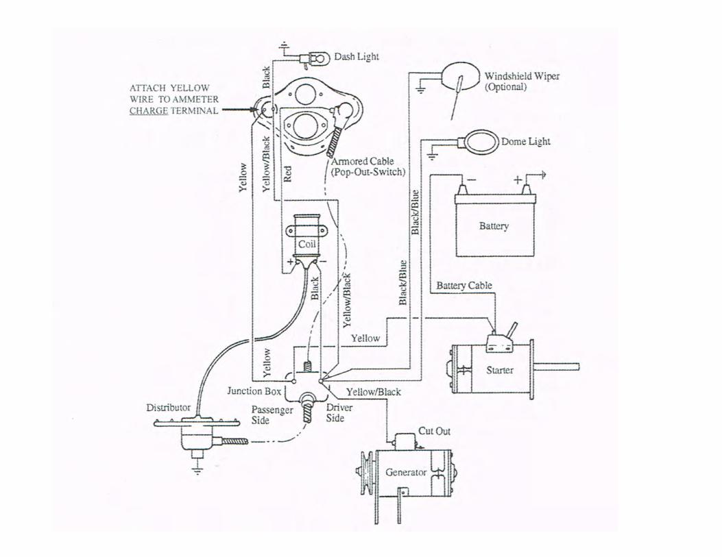
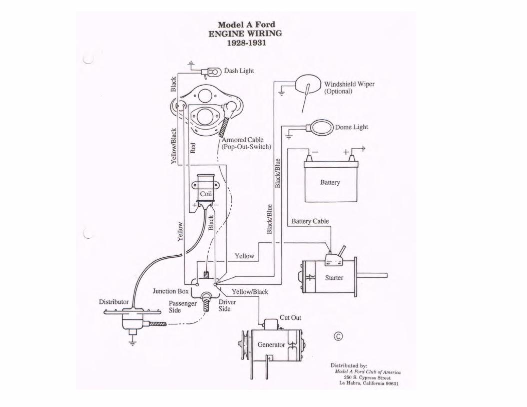
MODEL A FORD WIRING Reno...About Ford Wiring • Wires were cloth covered, rubber insulated • Ford...
85
MODEL A FORD WIRING Keeping the Current Flowing
Transcript of MODEL A FORD WIRING Reno...About Ford Wiring • Wires were cloth covered, rubber insulated • Ford...

MODEL A FORD WIRING
Keeping the Current Flowing
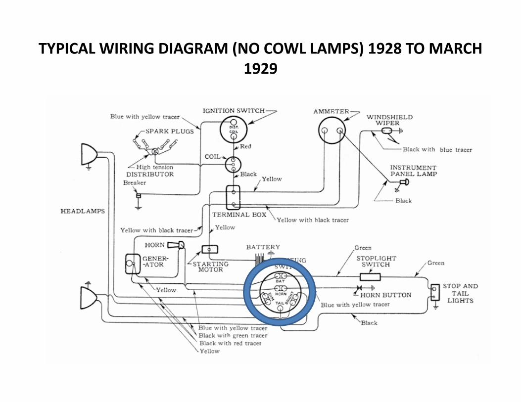
TYPICAL WIRING DIAGRAM (NO COWL LAMPS) 1928 TO MARCH 1929
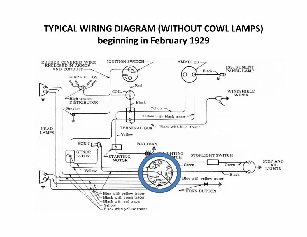
TYPICAL WIRING DIAGRAM (WITHOUT COWL LAMPS) beginning in February 1929
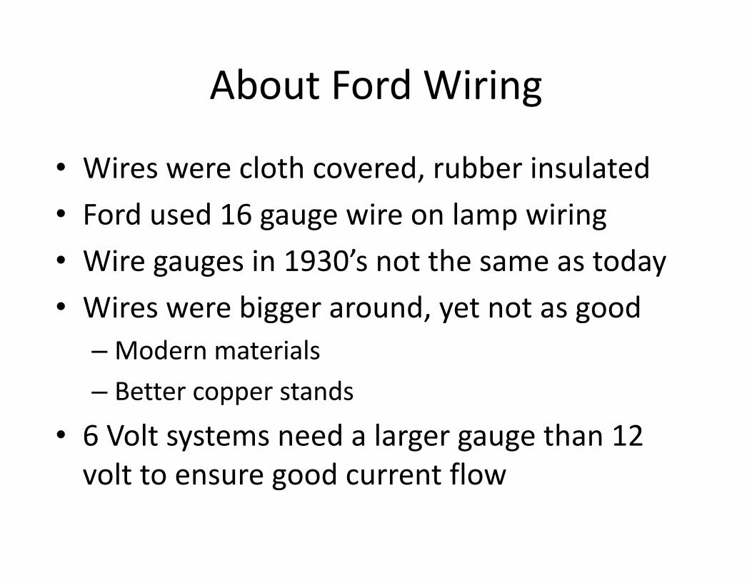
About Ford Wiring
• Wires were cloth covered, rubber insulated• Ford used 16 gauge wire on lamp wiring • Wire gauges in 1930’s not the same as today• Wires were bigger around, yet not as good–Modern materials– Better copper stands
• 6 Volt systems need a larger gauge than 12 volt to ensure good current flow
Stranded Wire vs Solid WireStranded wire is much more flexible than solid wire of equal size. For this reason, stranded wire is used when the wire needs to move around frequently, in automotive applications or in appliances for example. Conversely, solid wire is used when little or no movement is needed, such as home wiring. When working with your Model A used stranded wire for the best results. Ford used only stranded wire.

The Battery – Where it All Starts
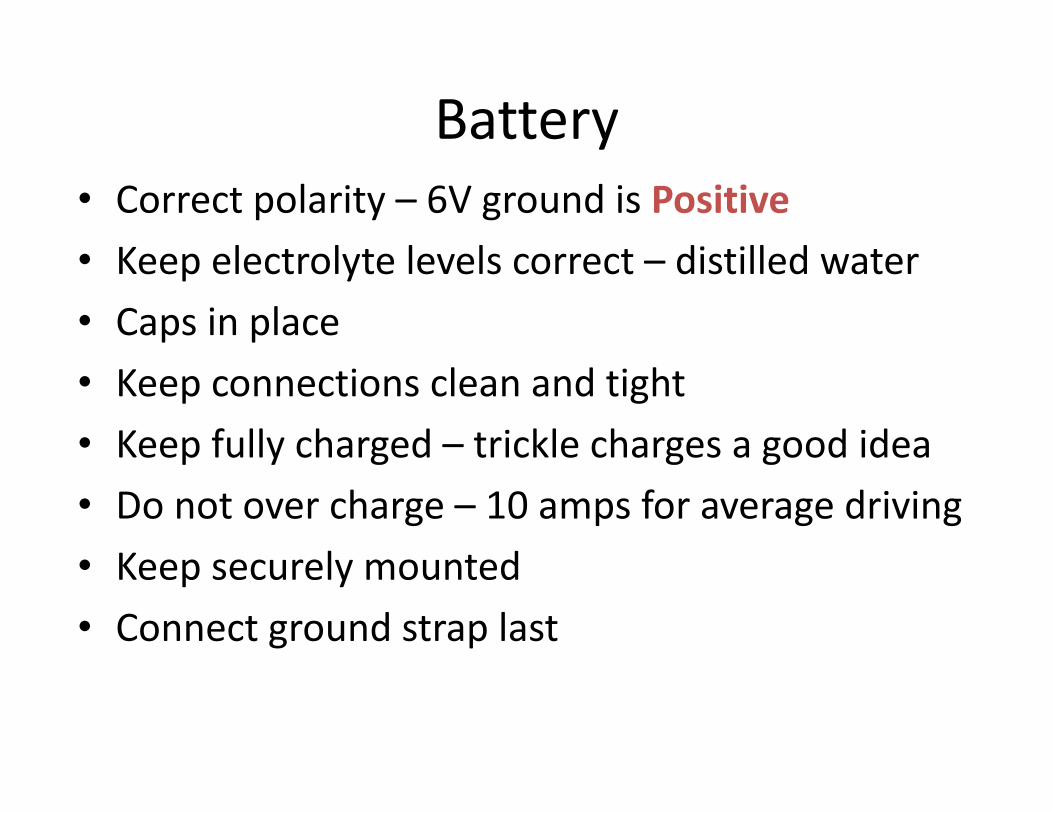
Battery • Correct polarity – 6V ground is Positive• Keep electrolyte levels correct – distilled water• Caps in place • Keep connections clean and tight• Keep fully charged – trickle charges a good idea • Do not over charge – 10 amps for average driving• Keep securely mounted• Connect ground strap last

Battery Ground Cable
Service Bulletin - March 1930
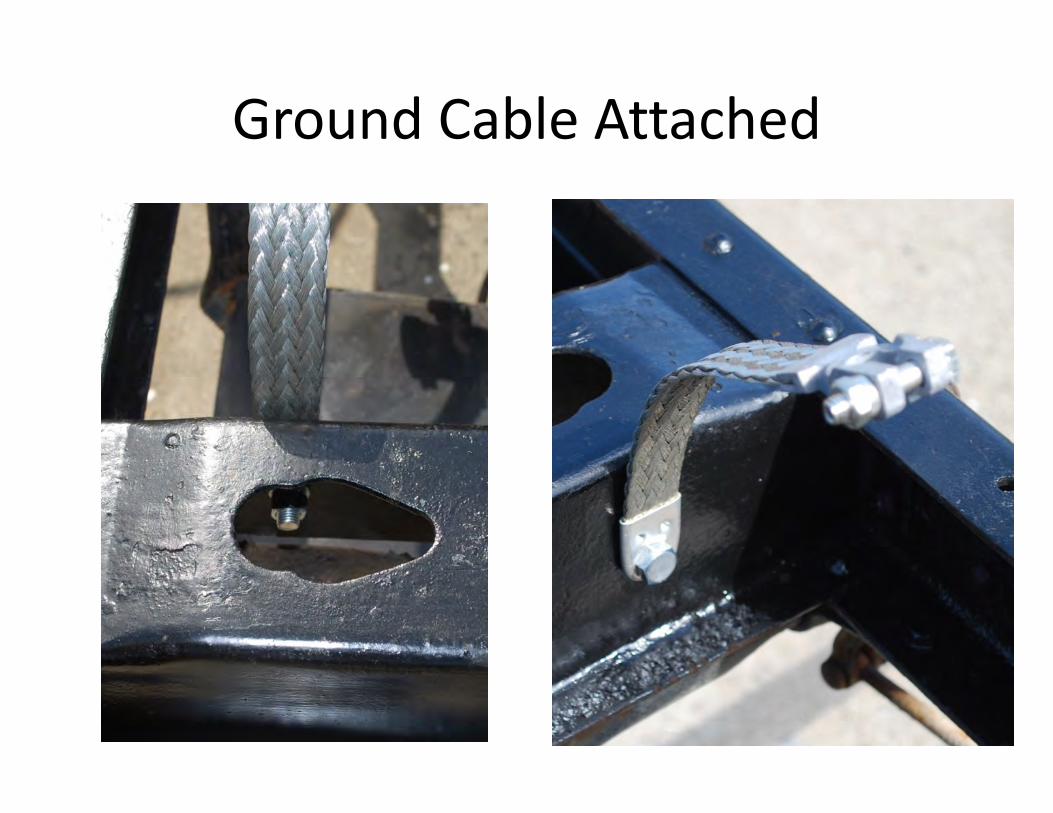
Ground Cable Attached

Modern Cable #2 wire
Model A Cable #1 wire
Service Bulletin – November 1929
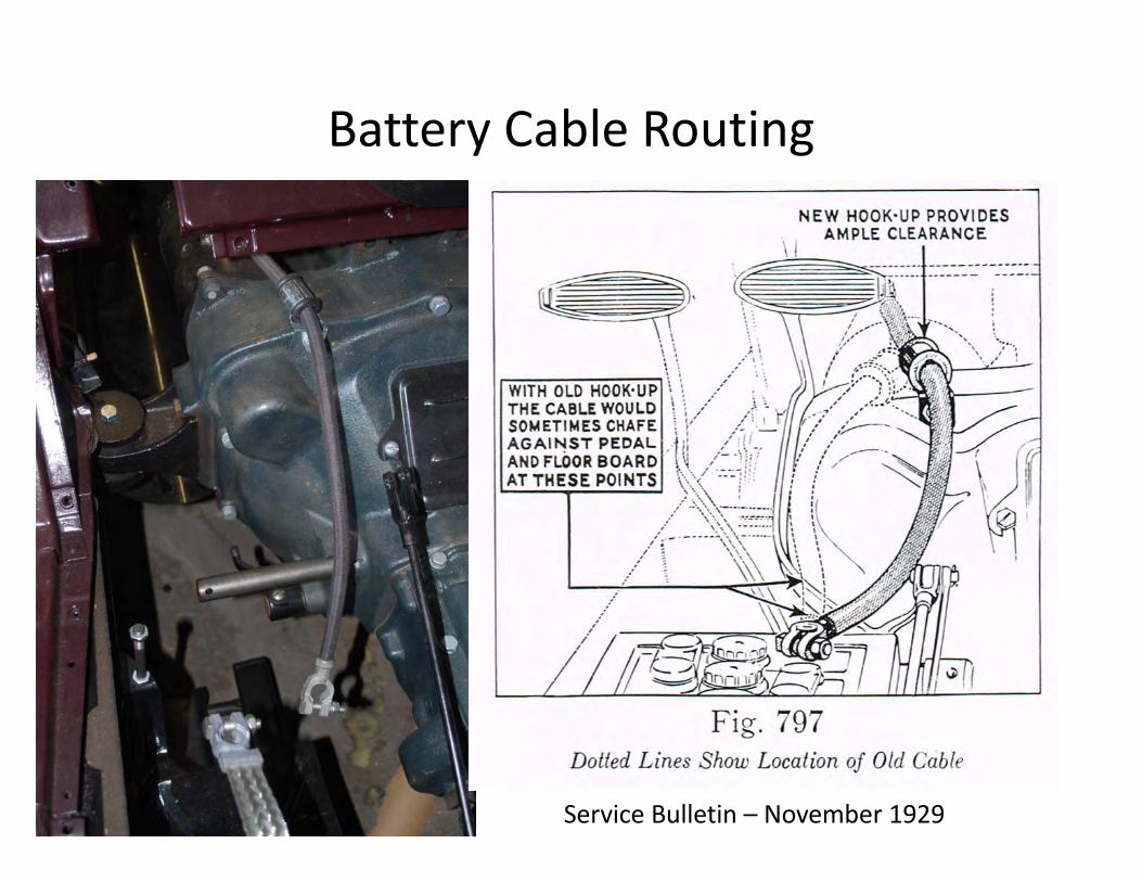
Battery Cable Routing
Service Bulletin – November 1929

Battery MountedUse care to ensure no contact with battery hold down

Safety Fuse
Black Enamel Paint
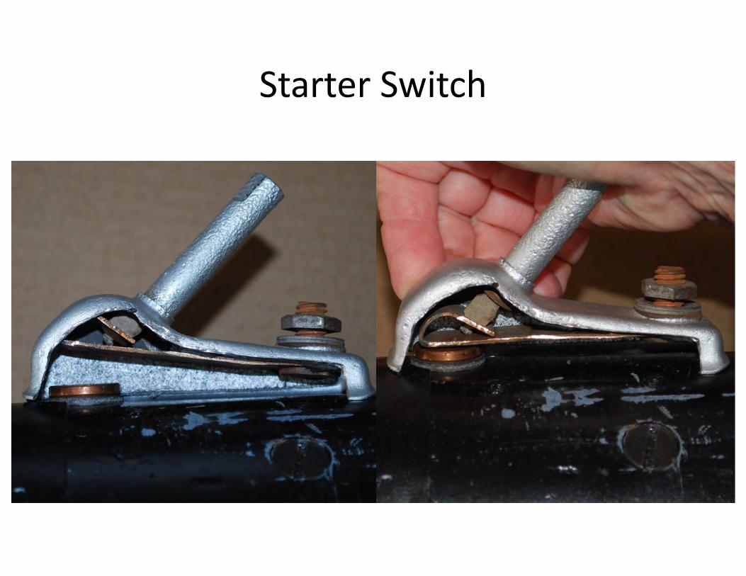
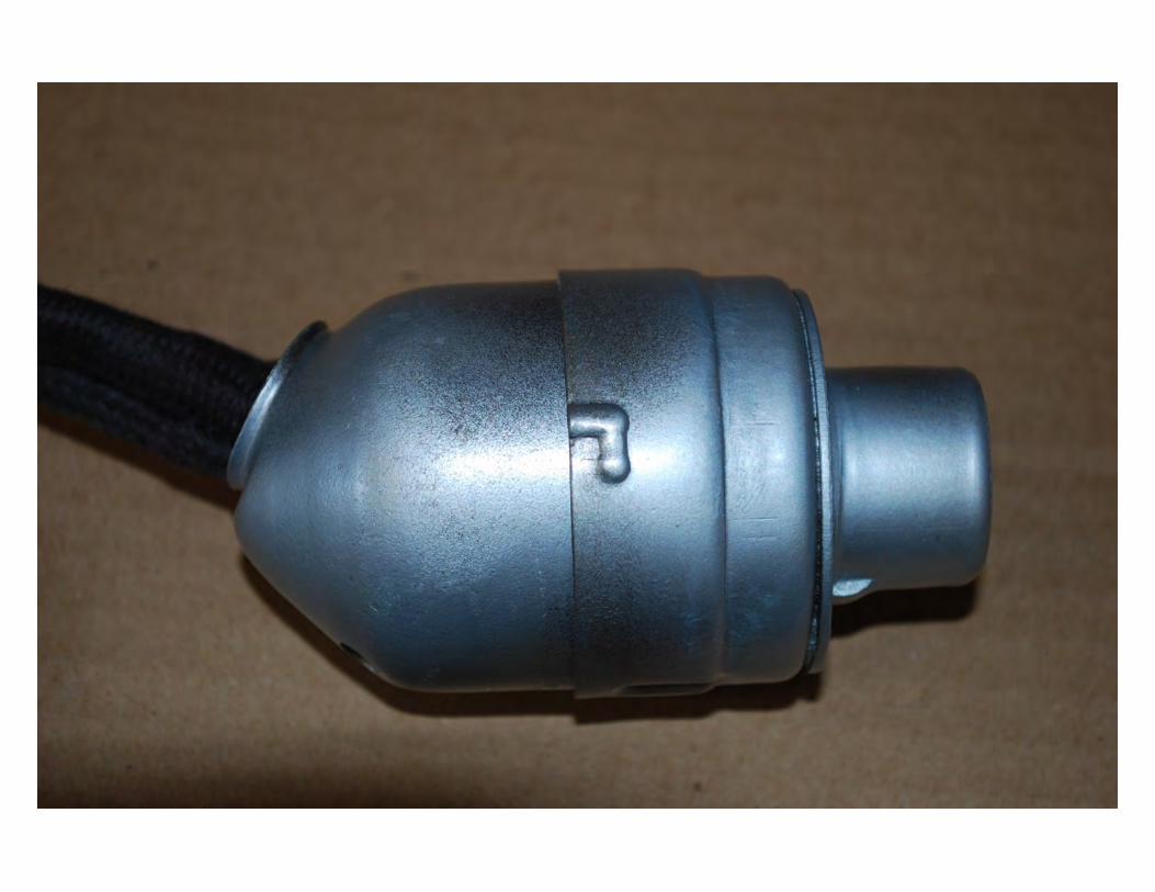
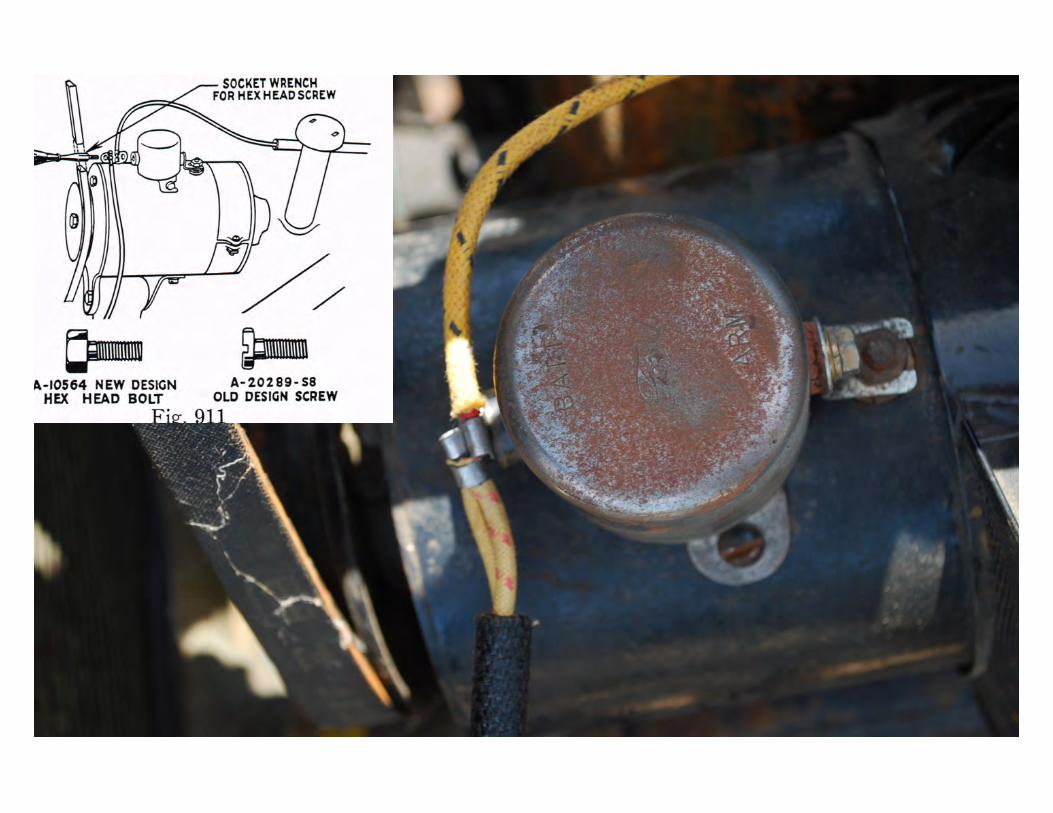
Starter Switch
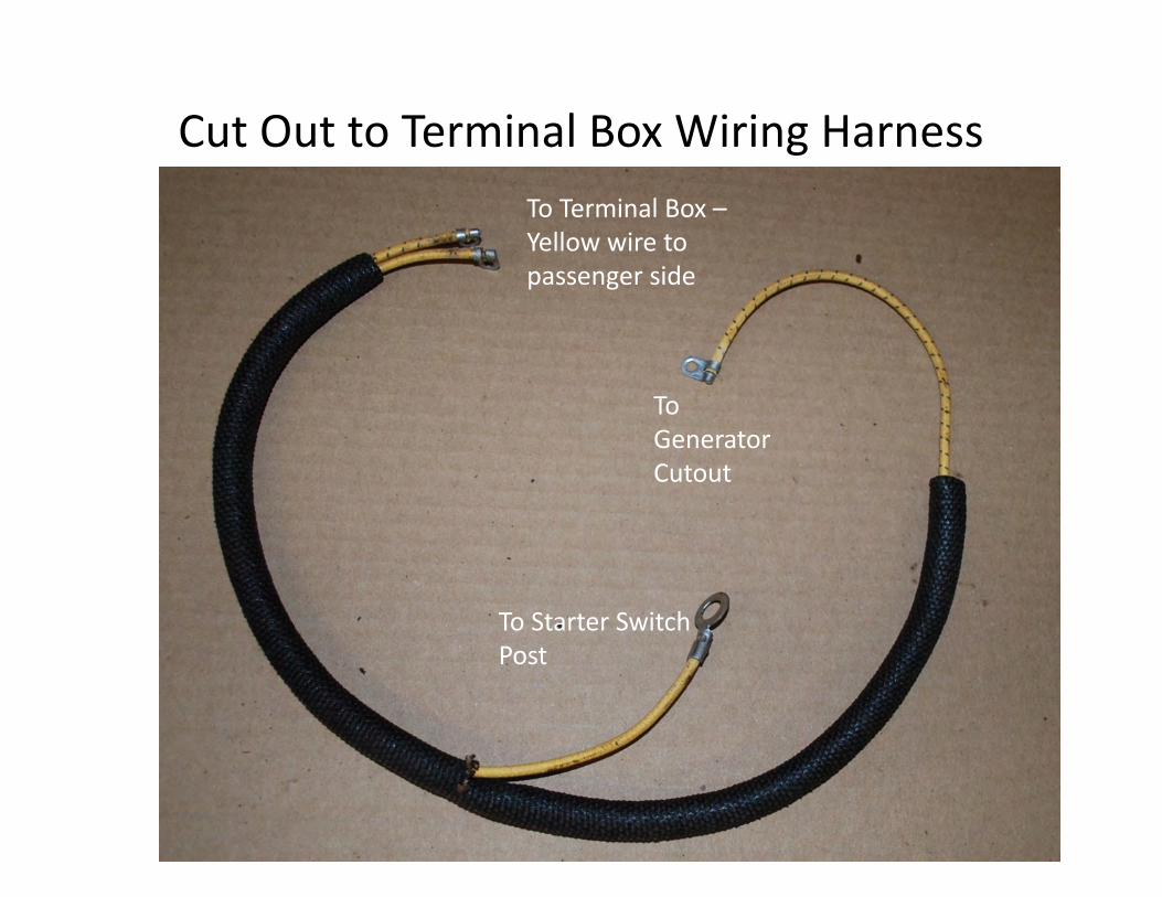
Cut Out to Terminal Box Wiring HarnessTo Terminal Box –Yellow wire to passenger side
To Generator Cutout
To Starter Switch Post
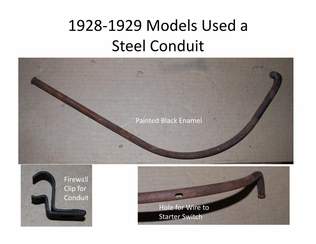
1928-1929 Models Used a Steel Conduit
Painted Black Enamel
Hole for Wire to Starter Switch
FirewallClip for Conduit

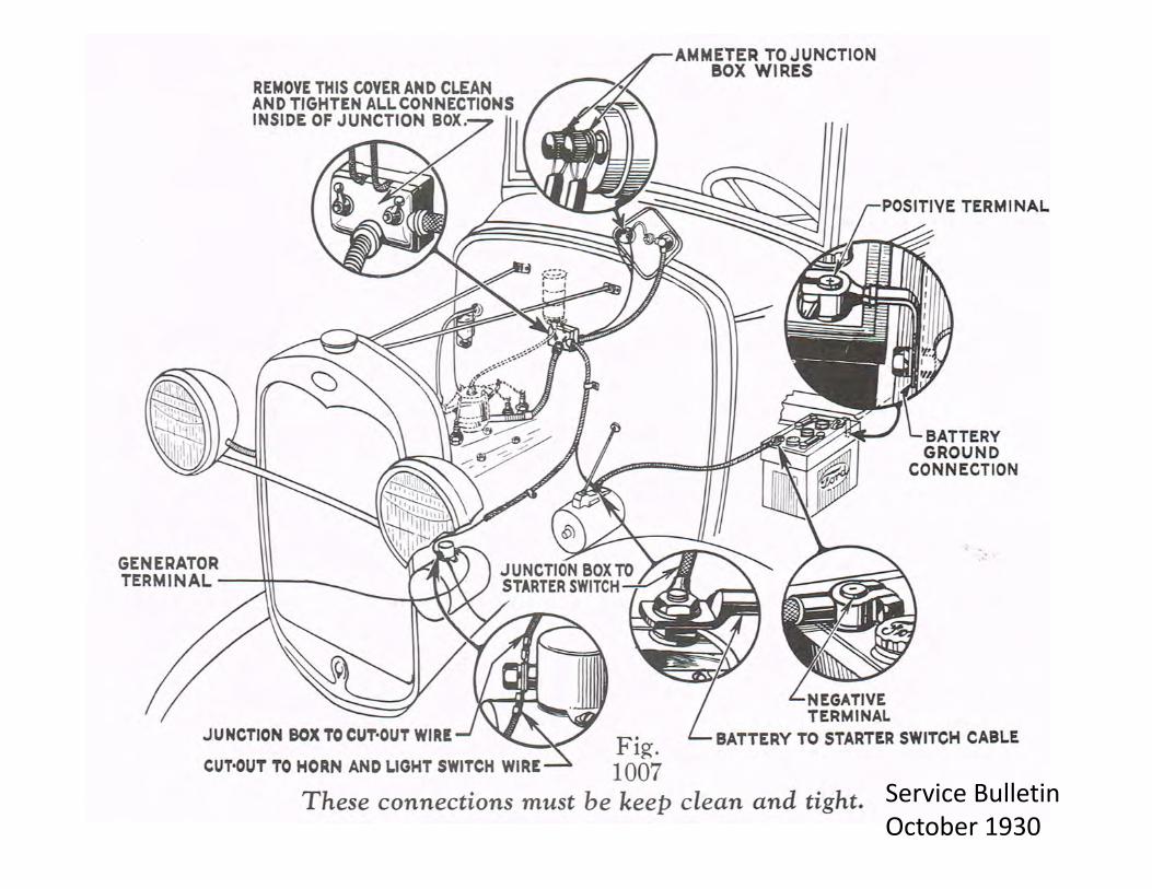
Connections
Terminal Box
Generator Cut Out

Cut Out Variations

Alternator

Dash Wiring to Terminal Box Harness
Amp Meter Discharge Side
Igniton Switch
Amp Meter Charge Side
Terminal BoxDriver’s SidePassenger’s Side
Coil Positive Post
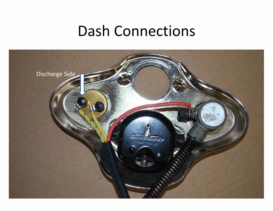
Dash Connections
Discharge Side

Ammeter

Pop Out Switch Internal
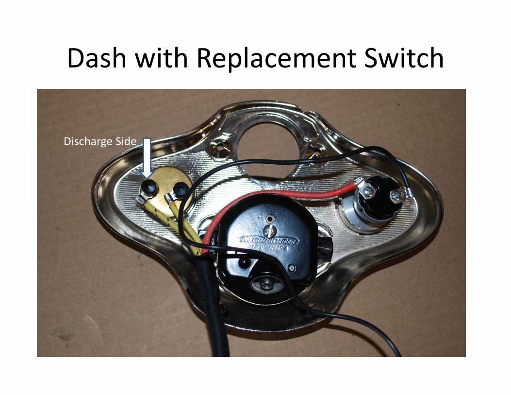
Dash with Replacement Switch
Discharge Side
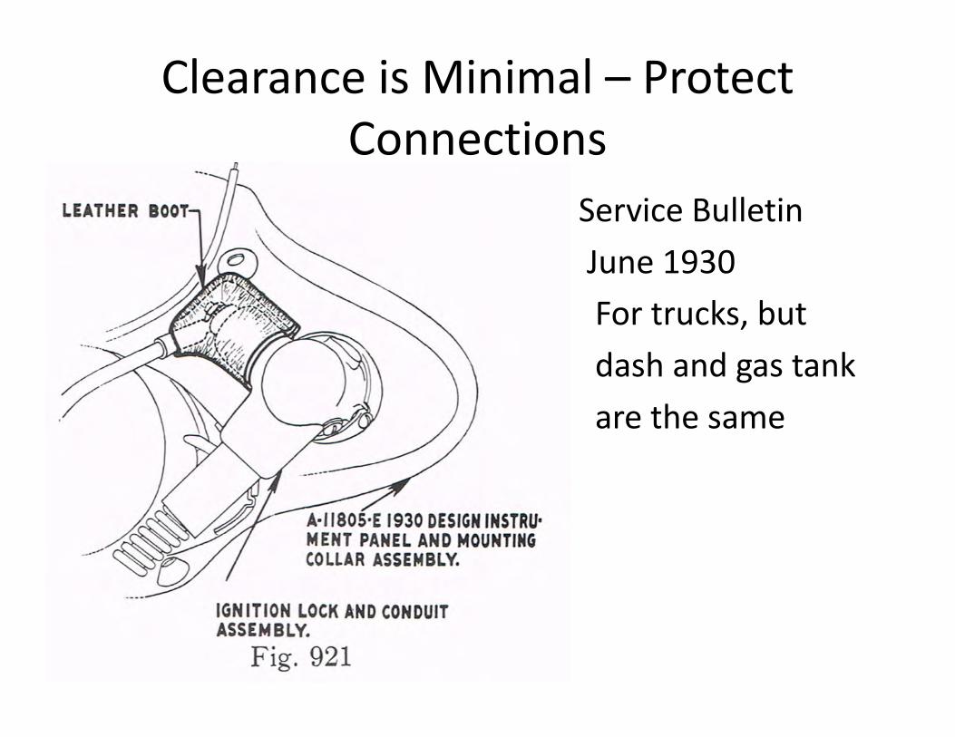
Clearance is Minimal – Protect Connections
• Service Bulletin • June 1930• For trucks, but • dash and gas tank • are the same
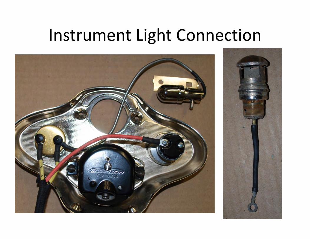
Instrument Light Connection
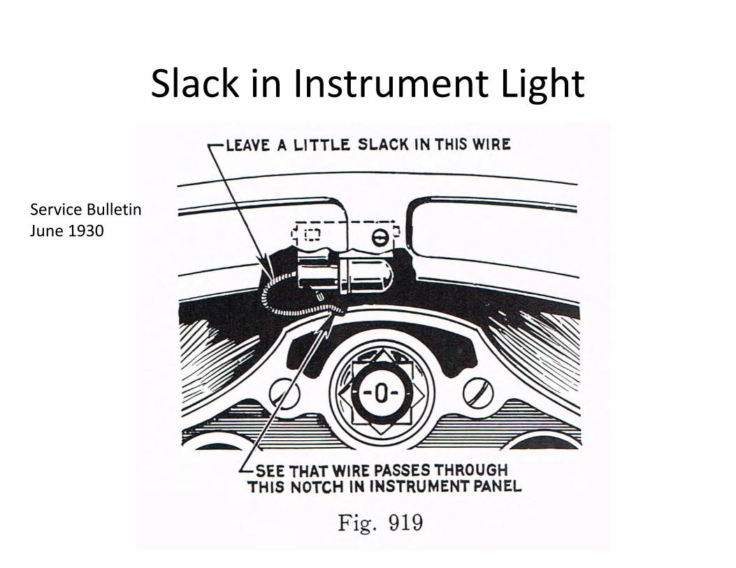
Slack in Instrument Light
Service BulletinJune 1930
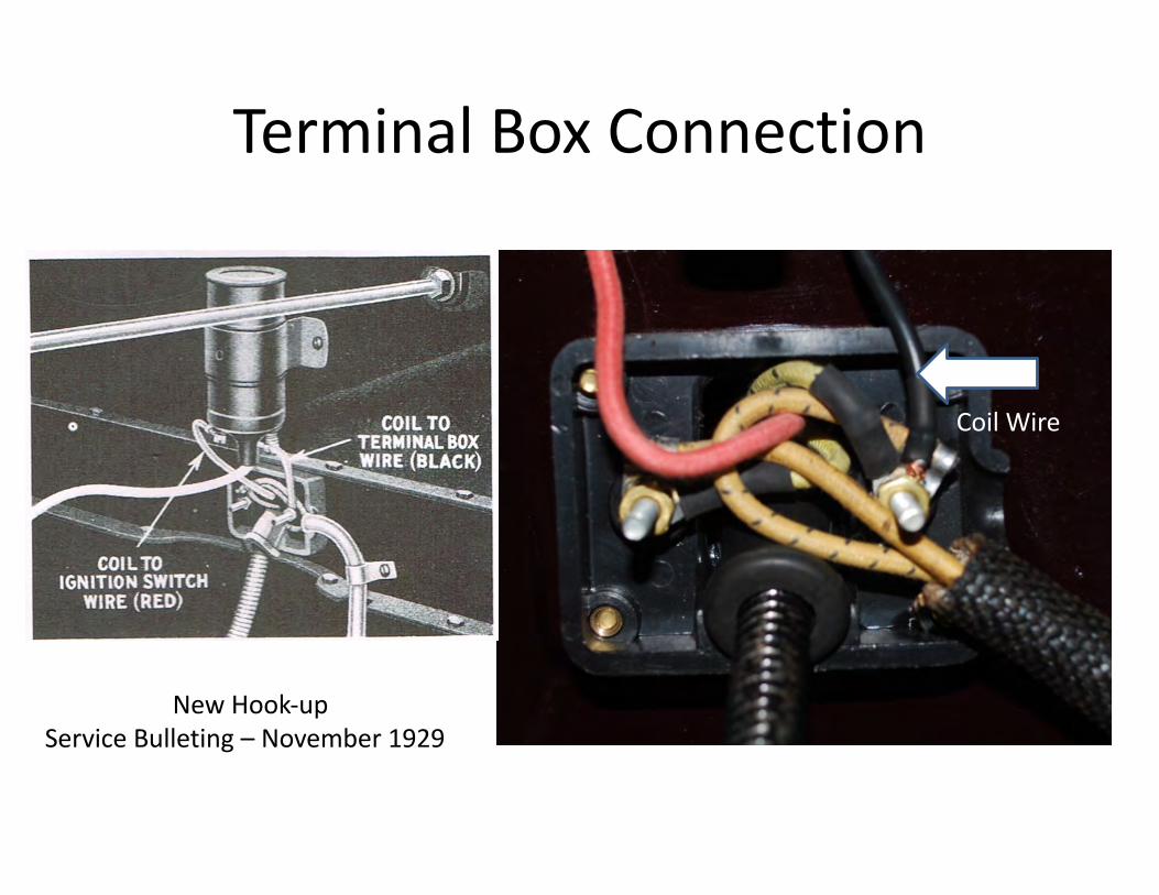
Terminal Box Connection
Coil Wire
New Hook-upService Bulleting – November 1929

Terminal Box Reproduction vs Original
Backside of OriginalBackside of Reproduction
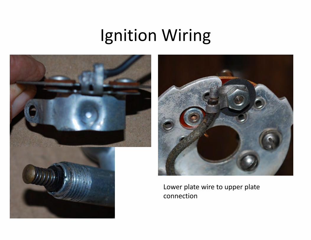
Ignition Wiring
Lower plate wire to upper plate connection
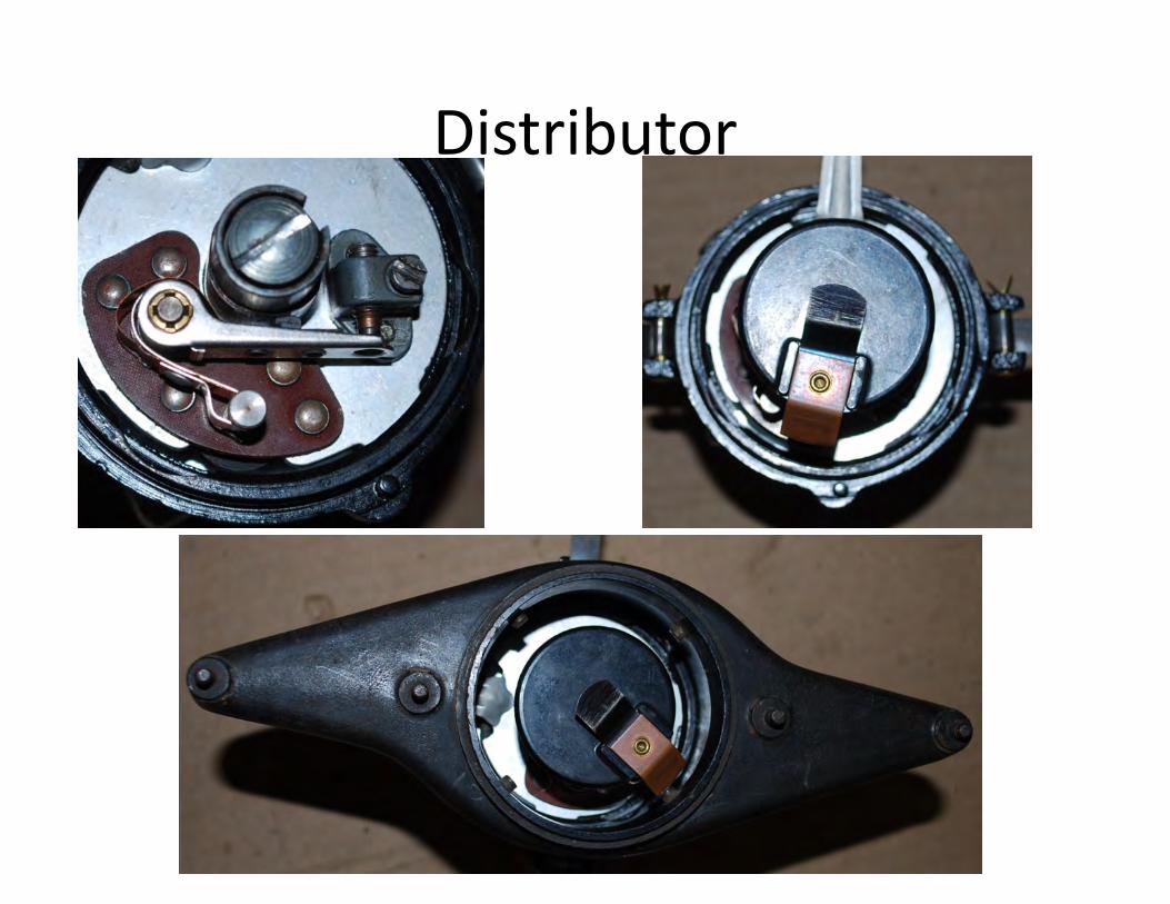
Distributor
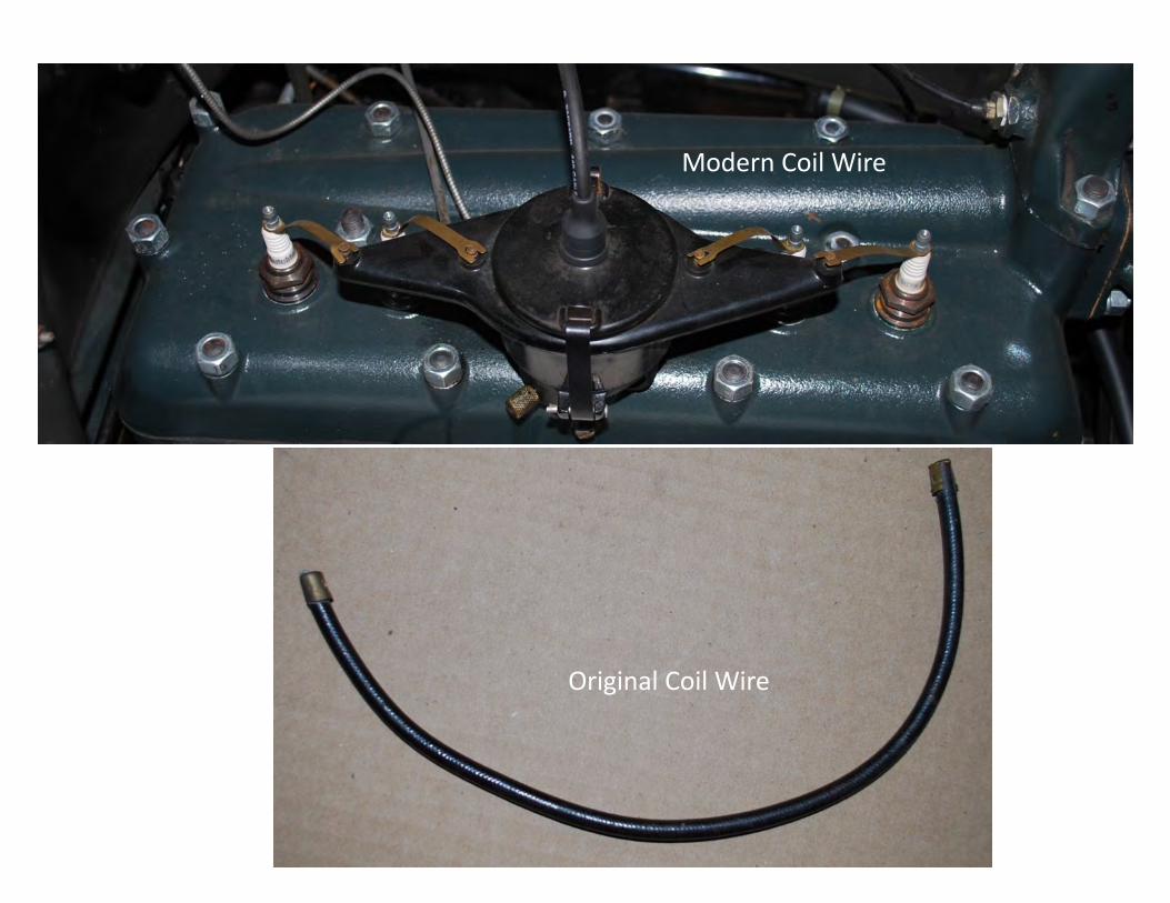
Original Coil Wire
Modern Coil Wire
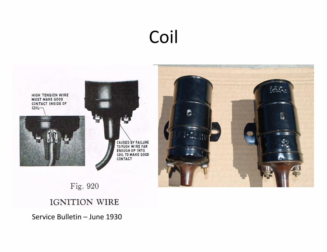
Coil
Service Bulletin – June 1930
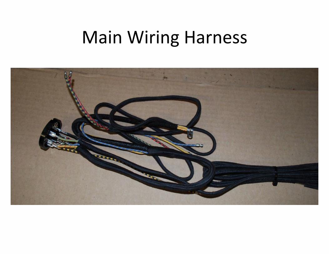
Main Wiring Harness
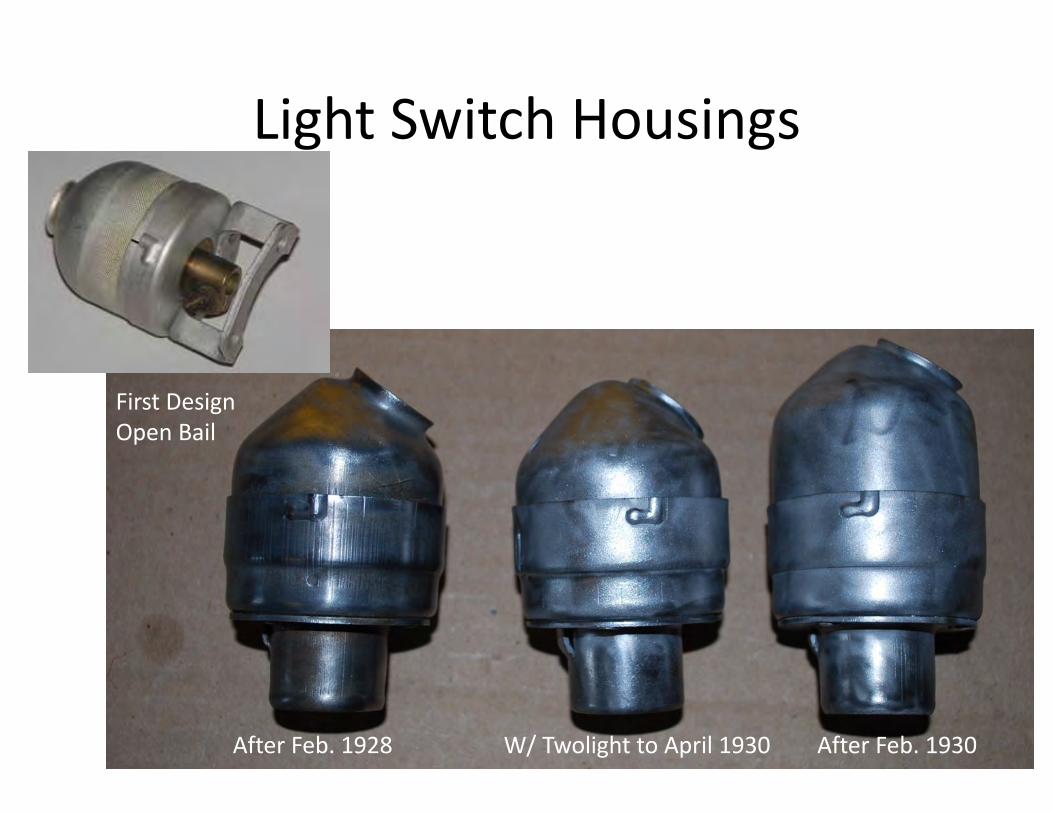
Light Switch Housings
After Feb. 1928 W/ Twolight to April 1930 After Feb. 1930
First DesignOpen Bail
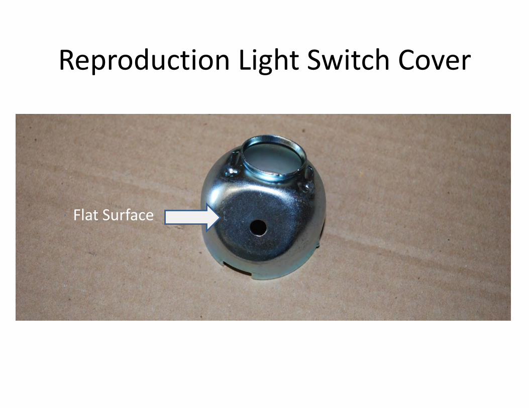
Reproduction Light Switch Cover
Flat Surface
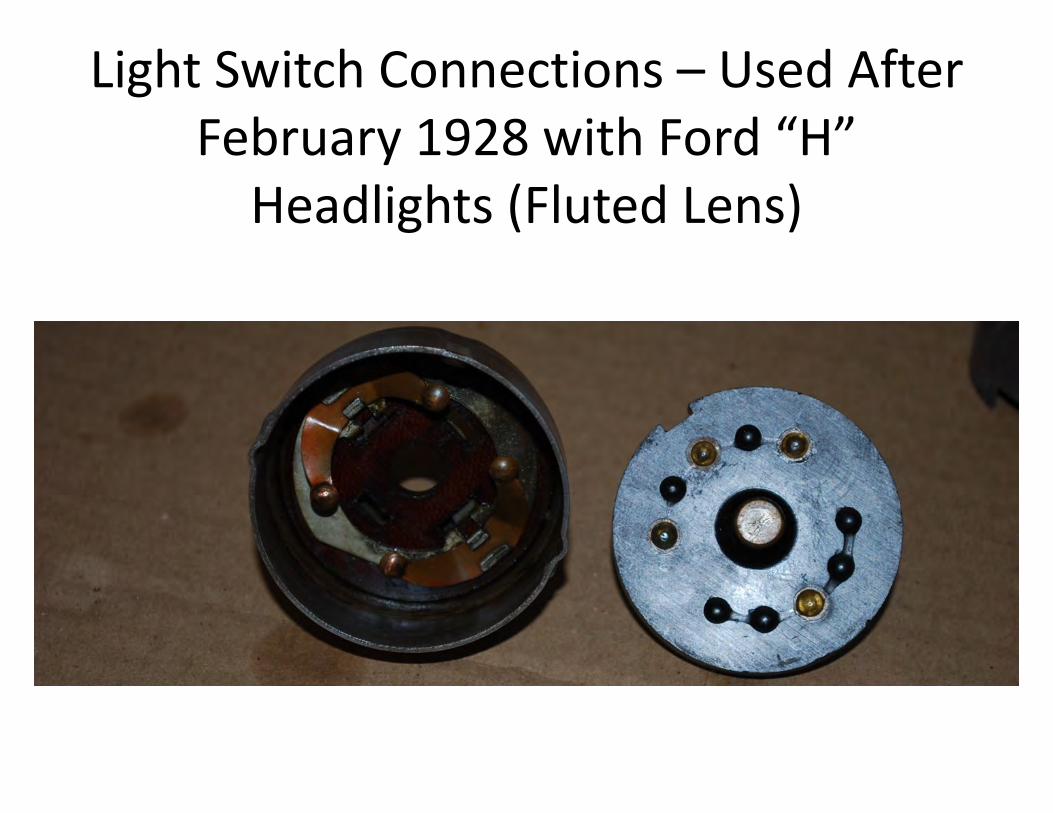
Light Switch Connections – Used After February 1928 with Ford “H”
Headlights (Fluted Lens)
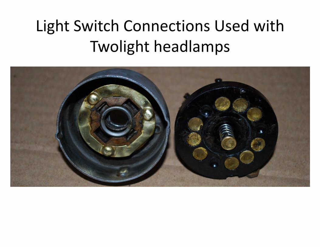
Light Switch Connections Used with Twolight headlamps
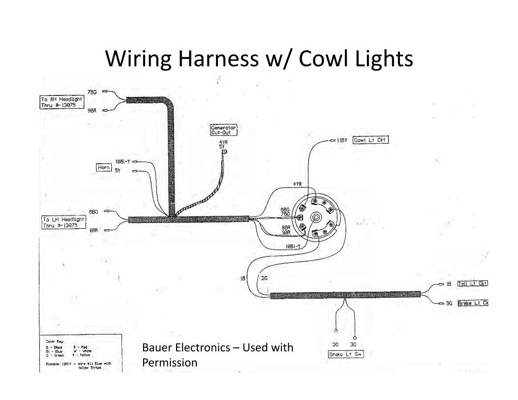
Wiring Harness w/ Cowl Lights
Bauer Electronics – Used with Permission
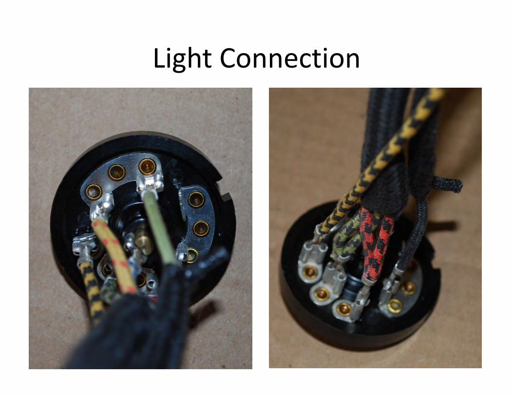
Light Connection
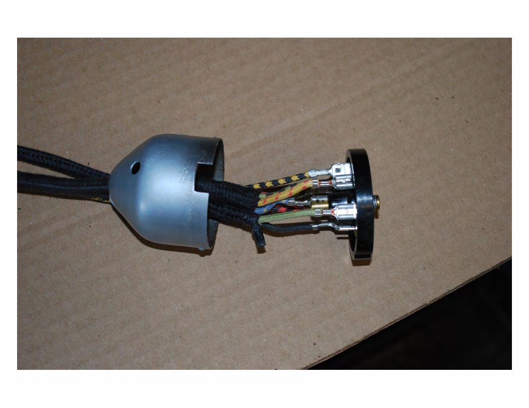
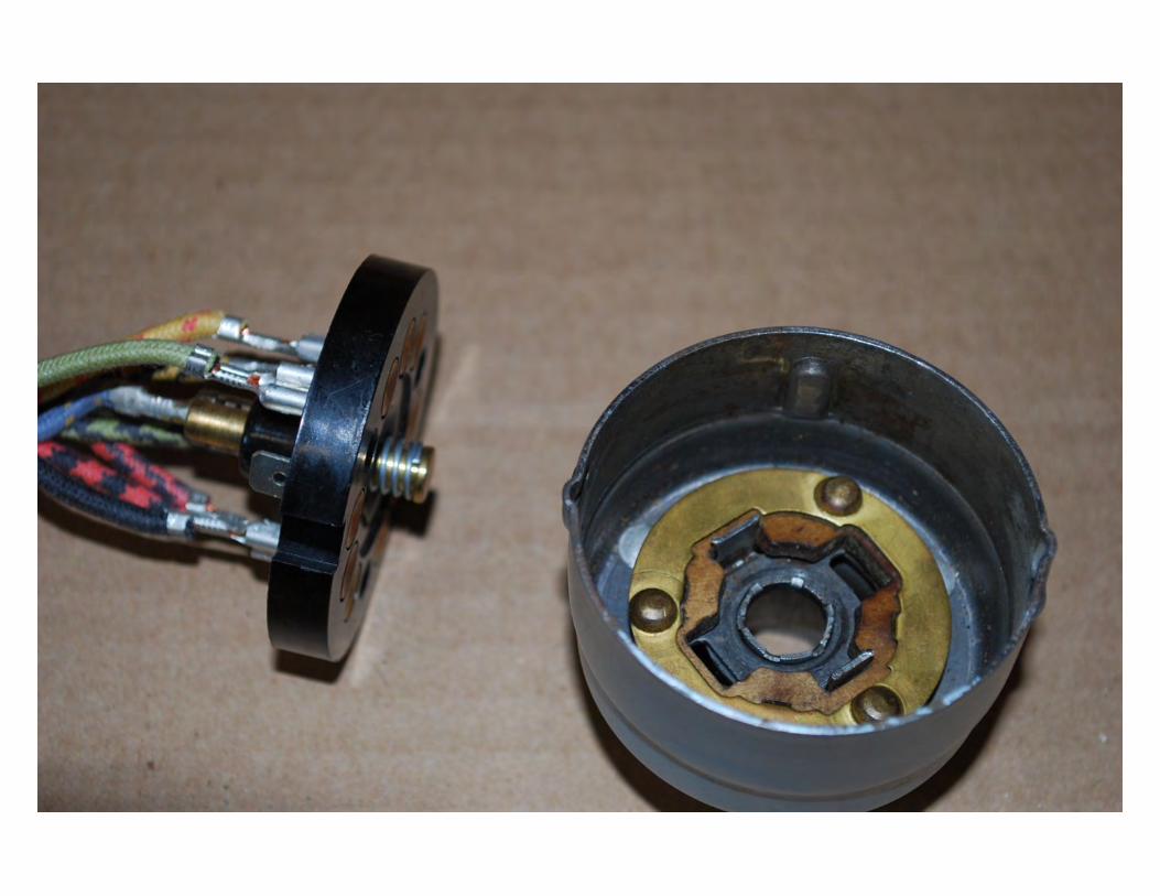
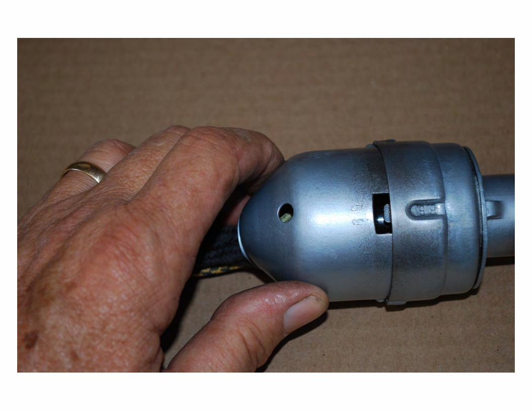

Switch Attachment
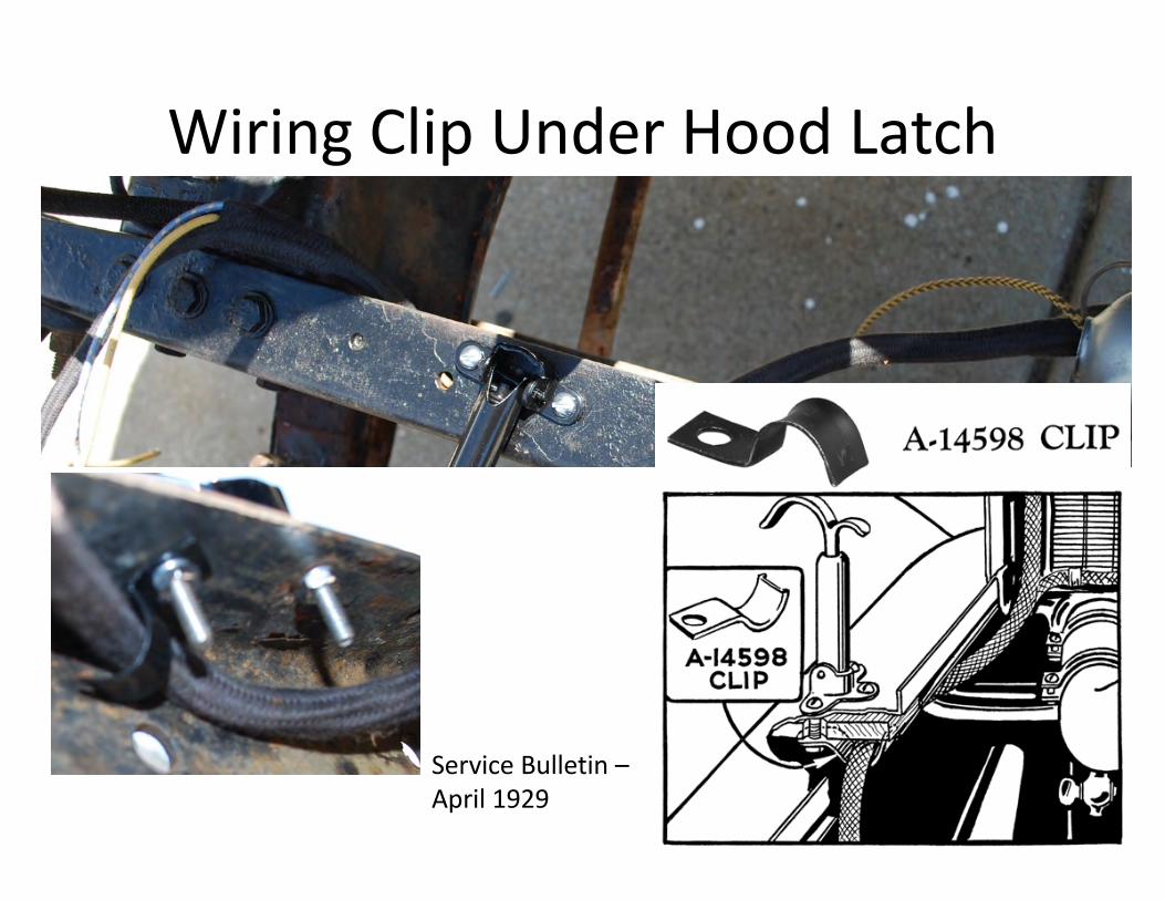
Wiring Clip Under Hood Latch
Service Bulletin –April 1929

Service Bulletin – June 1930

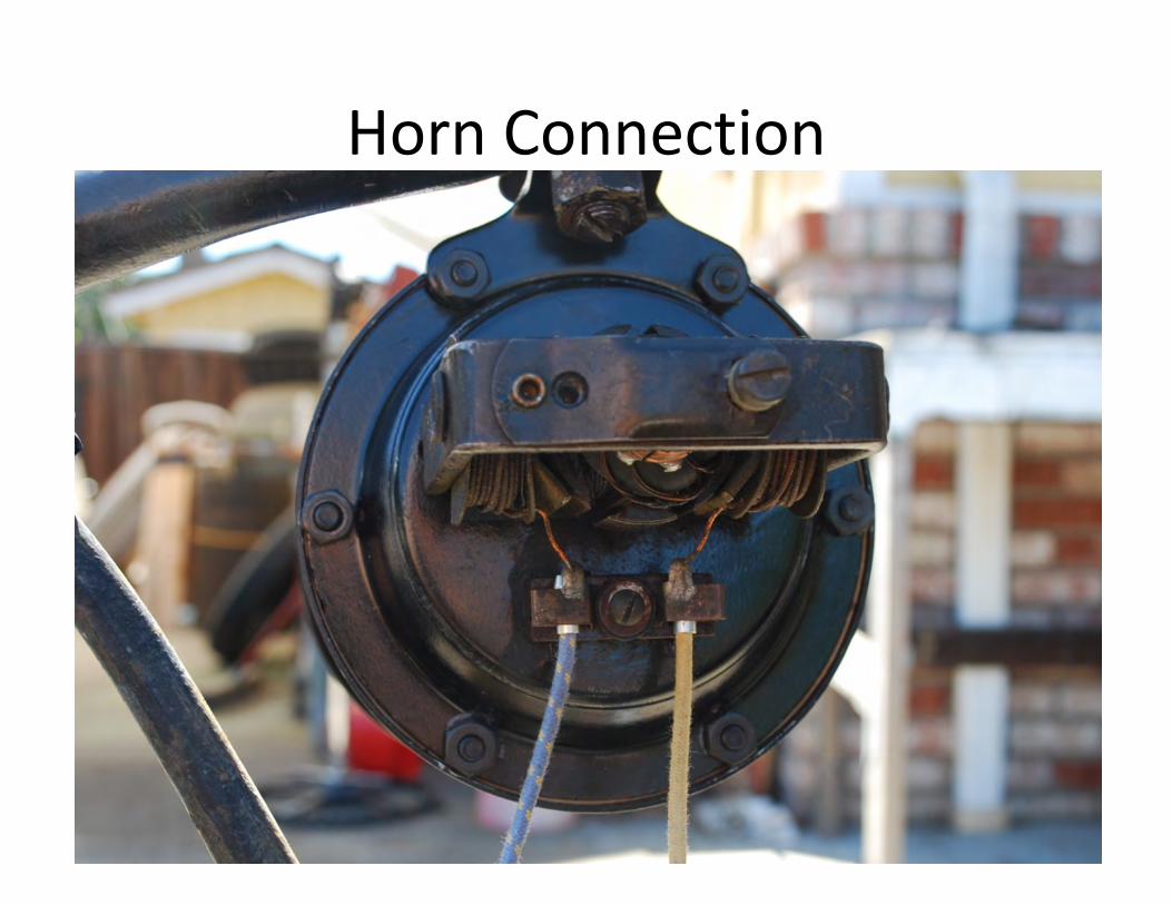
Horn Connection
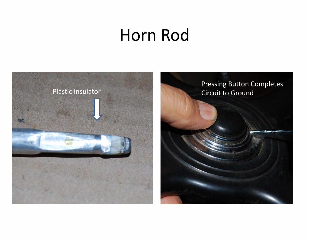
Horn Rod
Plastic InsulatorPressing Button Completes Circuit to Ground
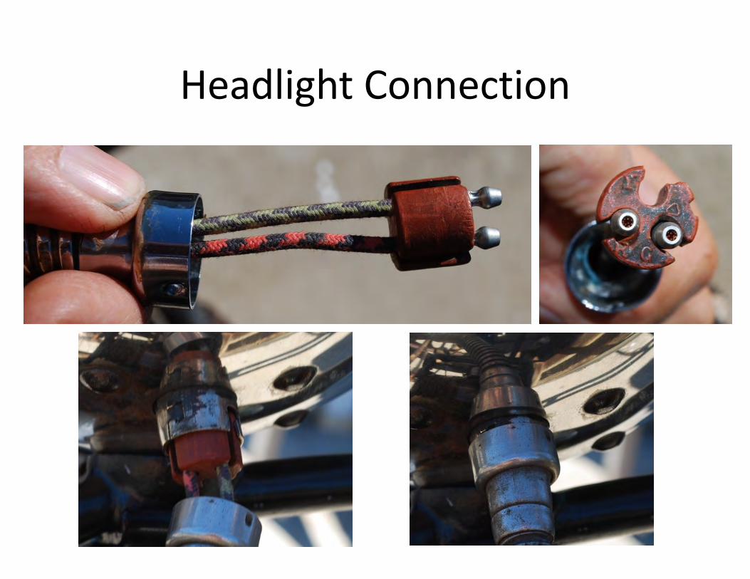
Headlight Connection
Courtesy of Bratton’s Antique Auto Parts
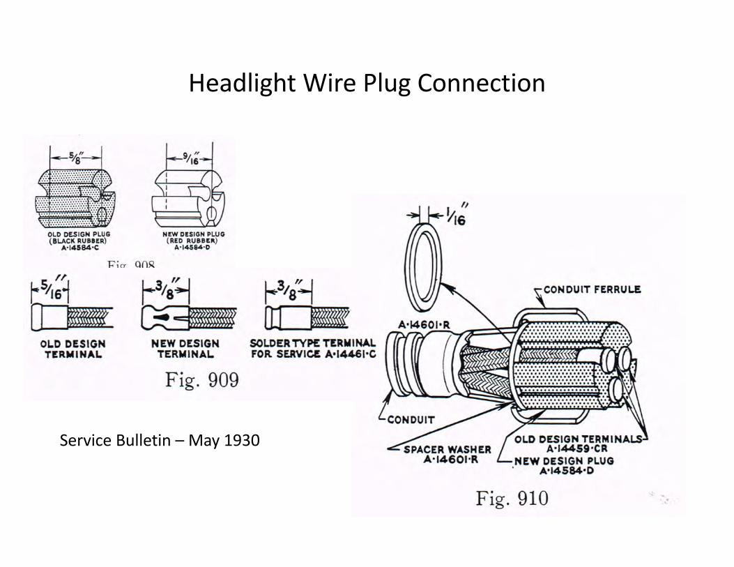
Service Bulletin – May 1930
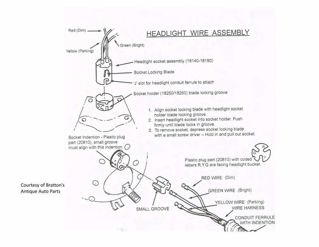
Headlight Wire Plug Connection
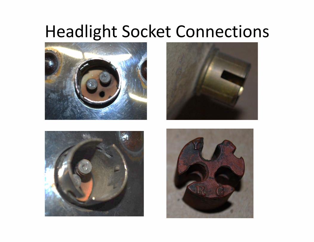
Headlight Socket Connections
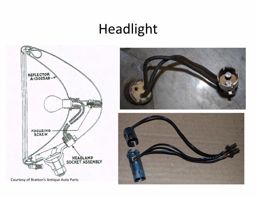
Headlight
Courtesy of Bratton’s Antique Auto Parts
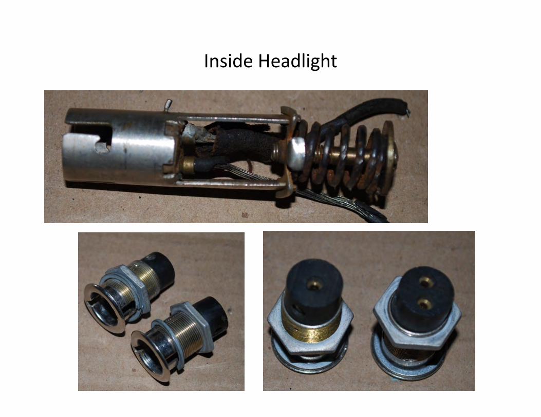
Inside Headlight
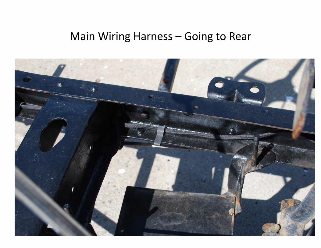
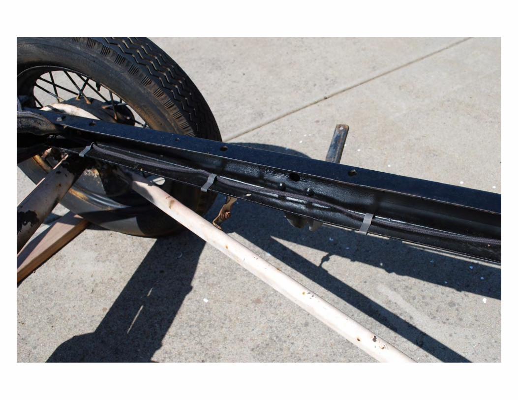
Main Wiring Harness – Going to Rear
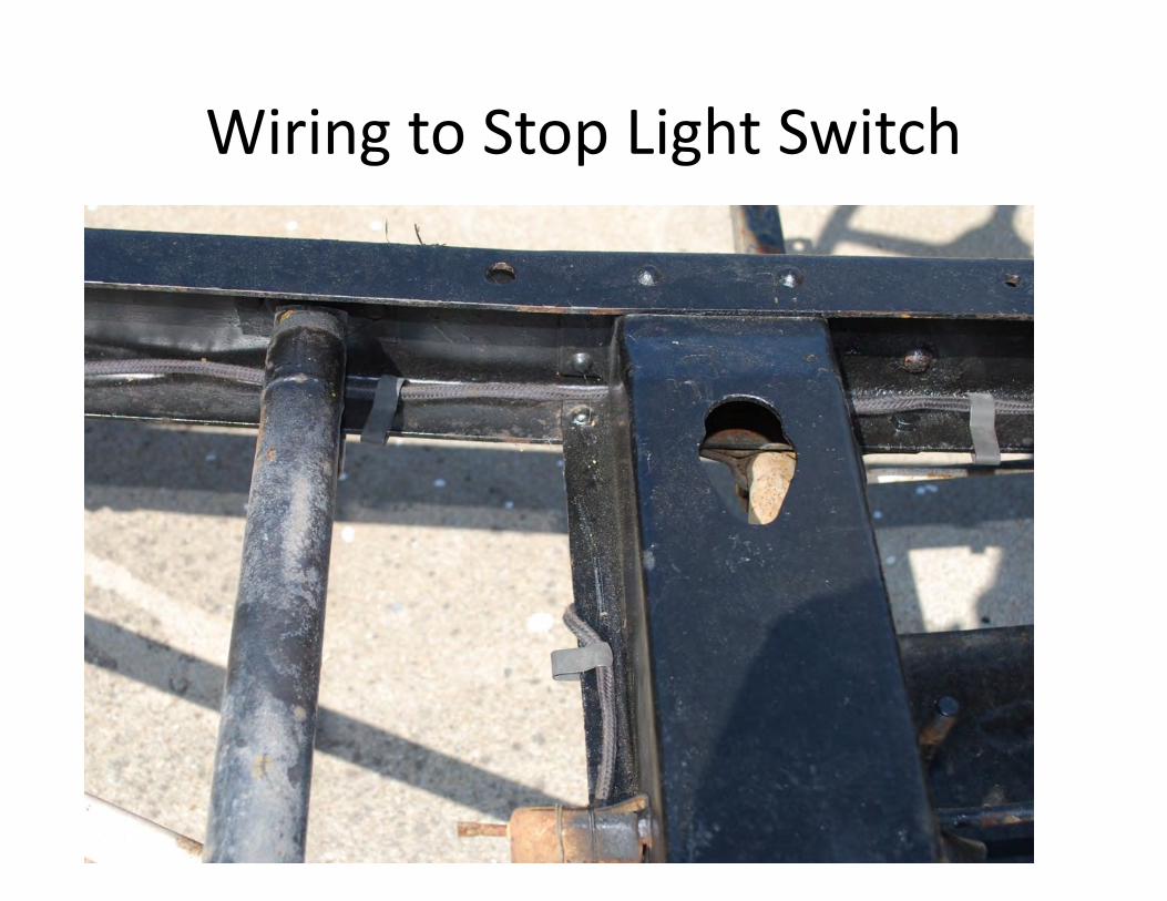
Wiring to Stop Light Switch
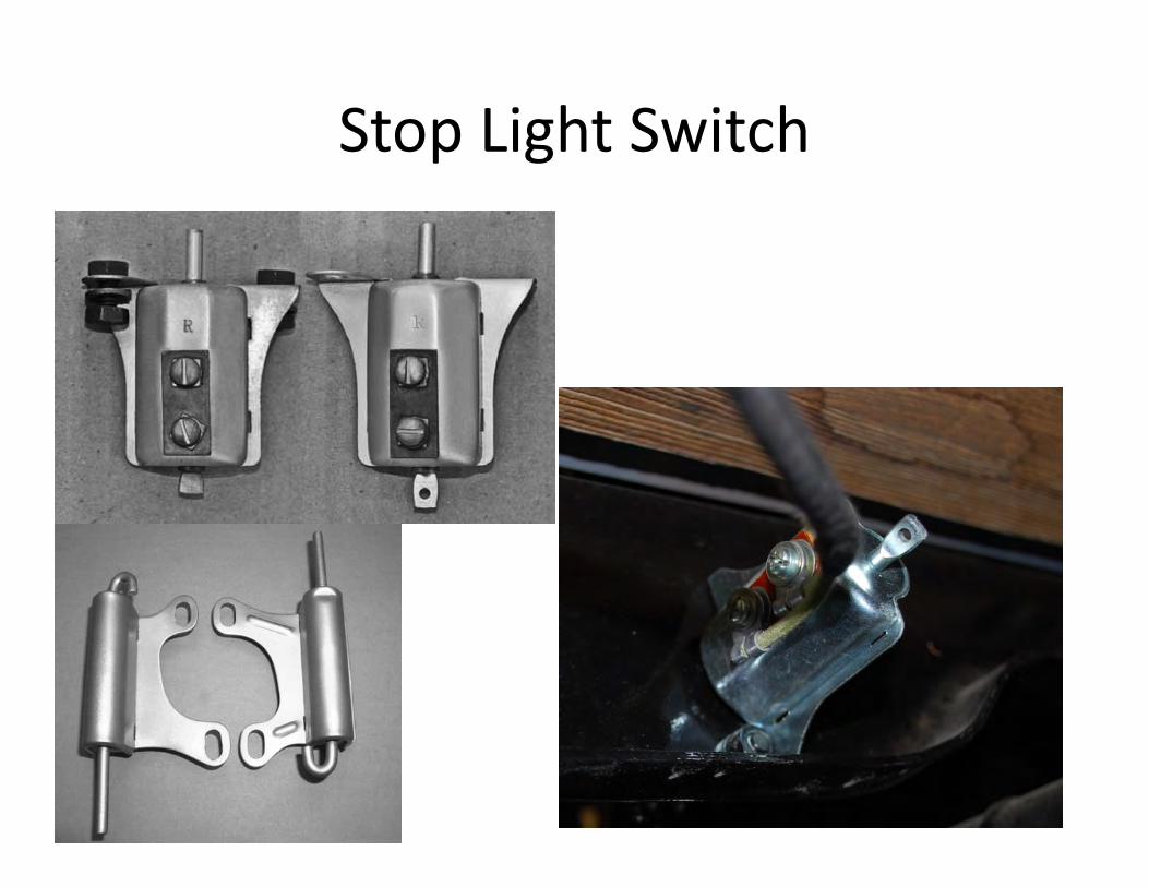
Stop Light Switch
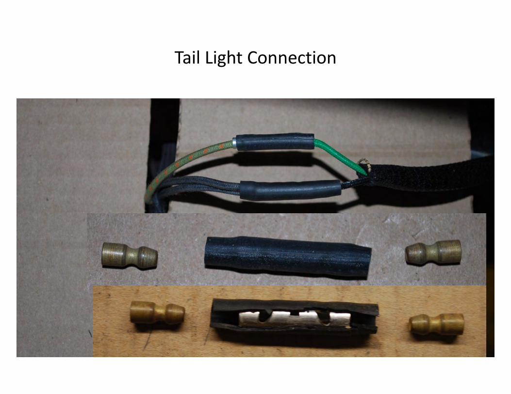
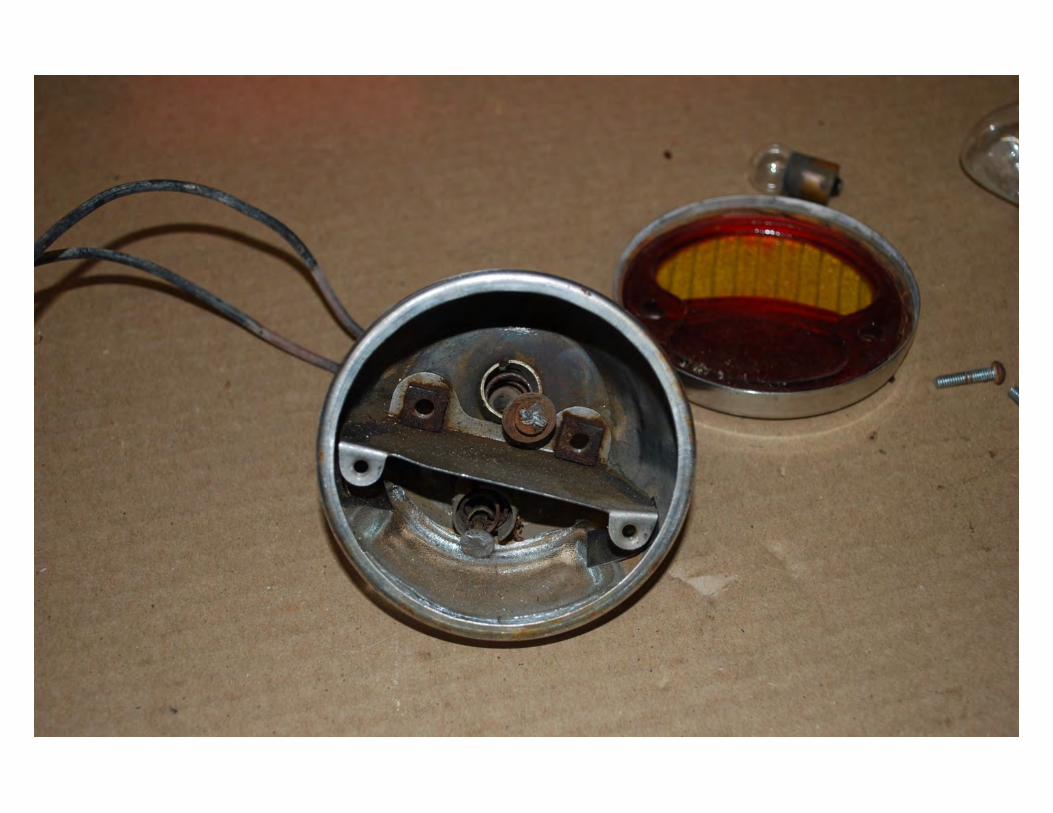
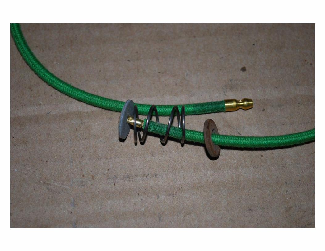
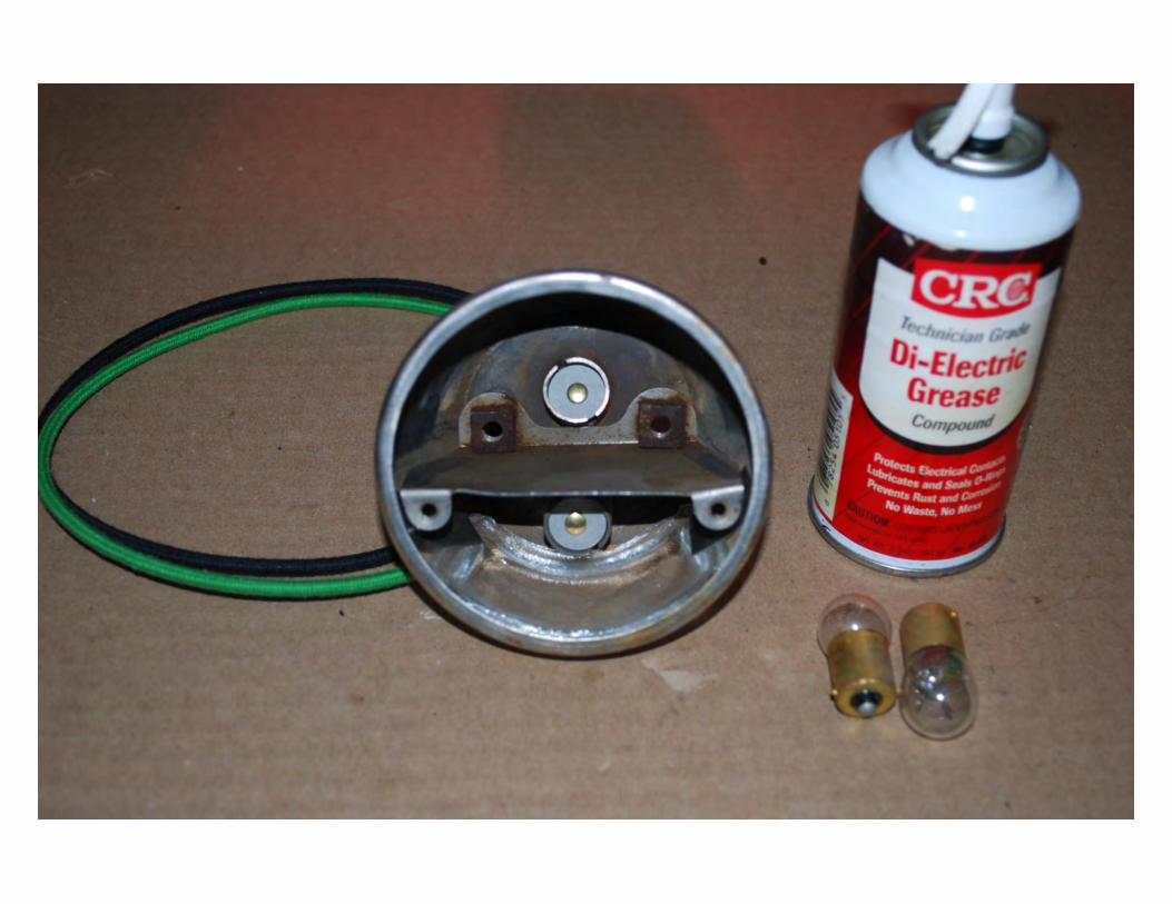
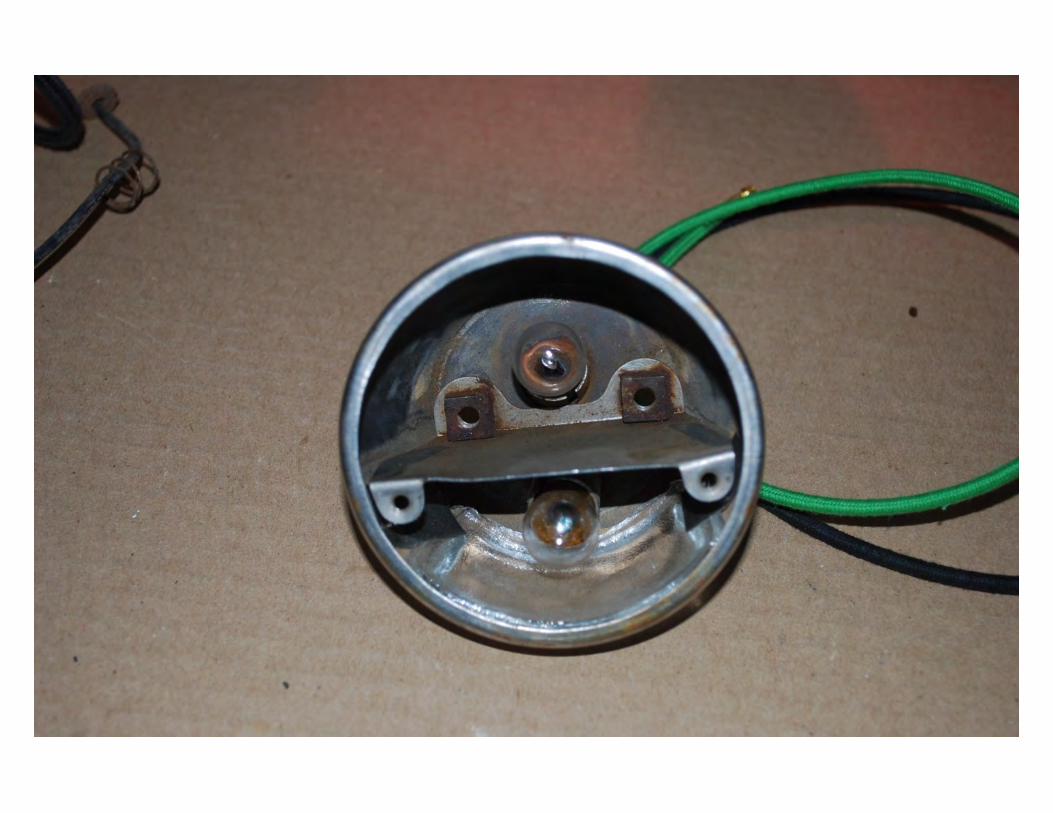
Tail Light Connection
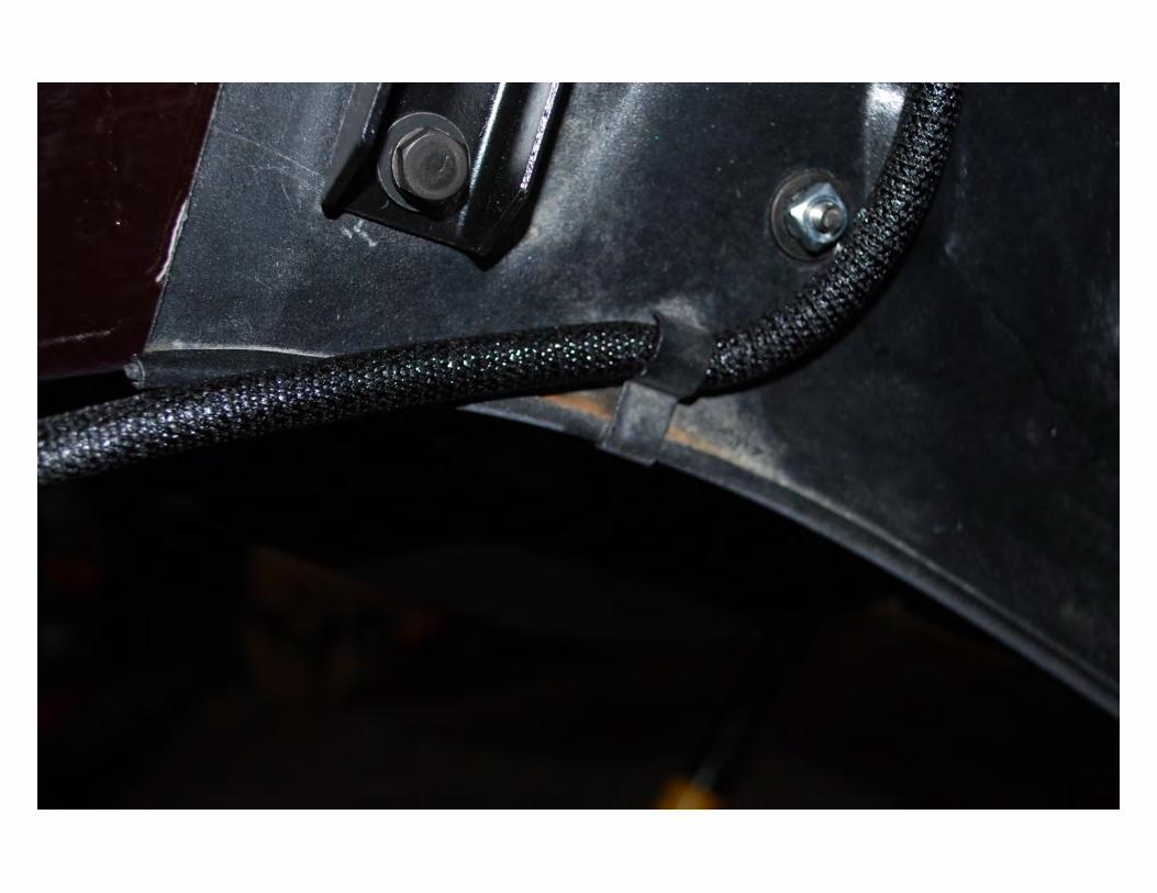
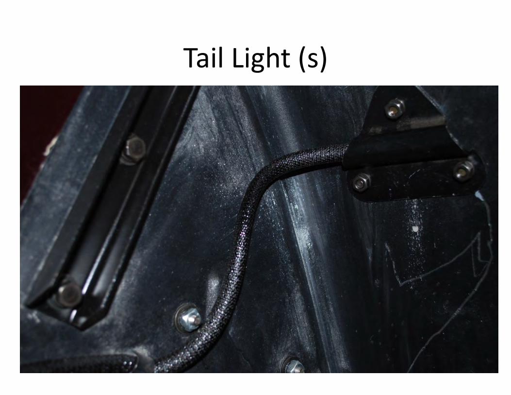
Tail Light (s)
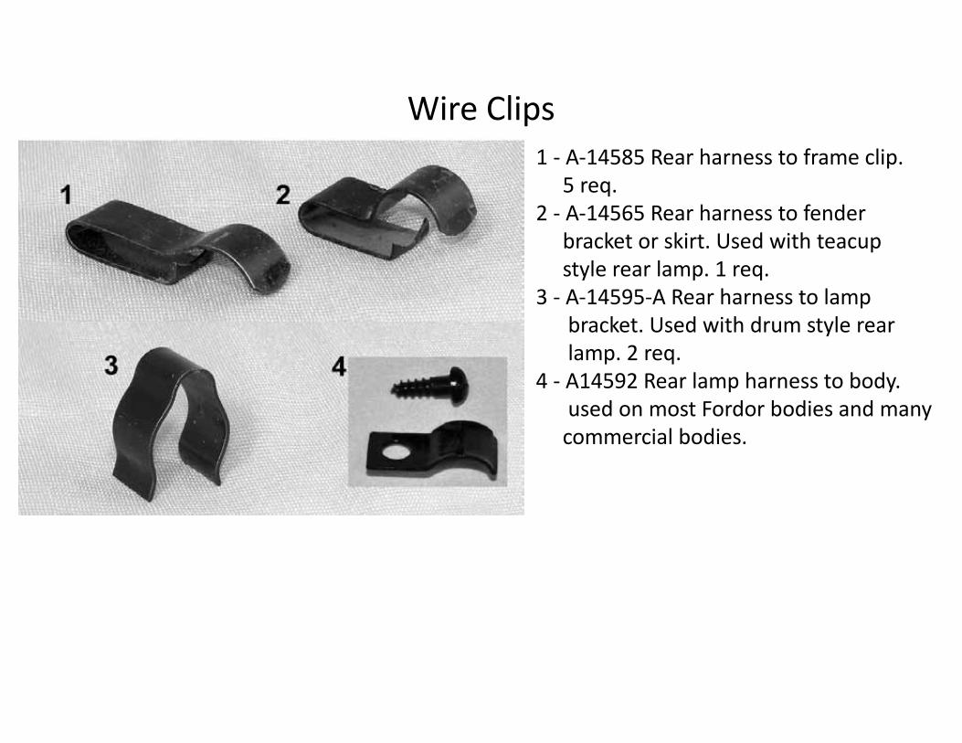
Wire Clips 1 - A-14585 Rear harness to frame clip.
5 req.2 - A-14565 Rear harness to fender
bracket or skirt. Used with teacup style rear lamp. 1 req.
3 - A-14595-A Rear harness to lamp bracket. Used with drum style rear lamp. 2 req.
4 - A14592 Rear lamp harness to body. used on most Fordor bodies and many
commercial bodies.
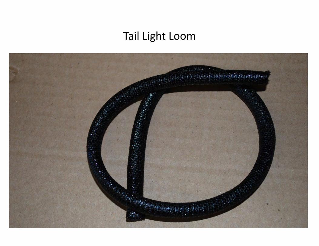
Tail Light Loom
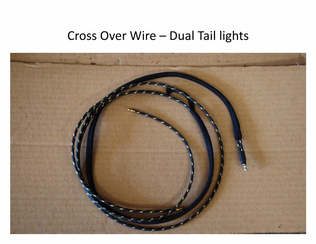
Cross Over Wire – Dual Tail lights
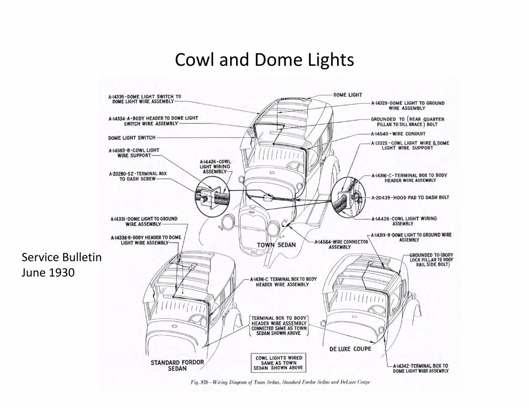
Cowl and Dome Lights
Service BulletinJune 1930
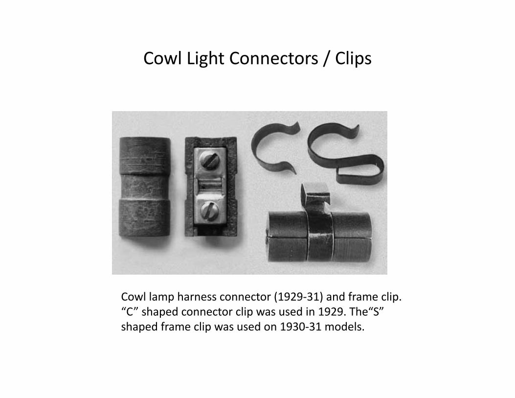
Cowl Light Connectors / Clips
Cowl lamp harness connector (1929-31) and frame clip. “C” shaped connector clip was used in 1929. The“S” shaped frame clip was used on 1930-31 models.
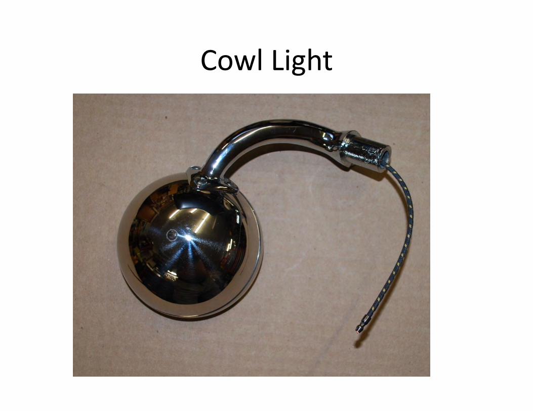
Cowl Light
Service BulletinOctober 1930

Turn Signals
Bauer Electronics – Used with Permission
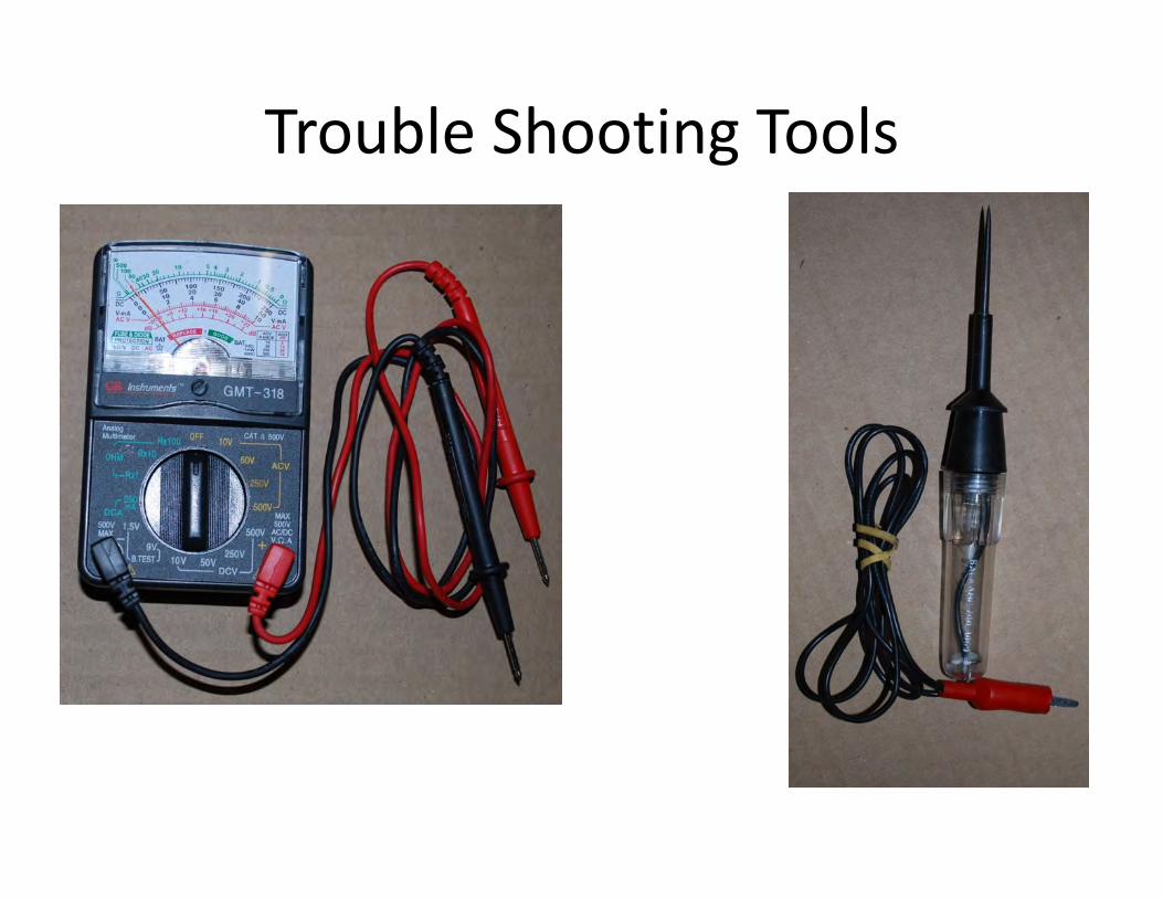
Trouble Shooting Tools

Where To Find Voltage
From Model A Ford Mechanics Handbook by Les Andrews – Available from MAFCA
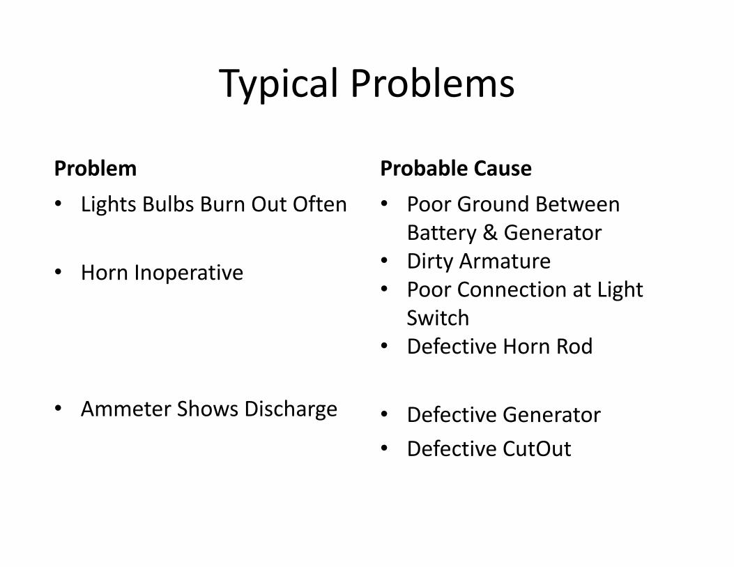
Typical Problems
Problem• Lights Bulbs Burn Out Often
• Horn Inoperative
• Ammeter Shows Discharge
Probable Cause • Poor Ground Between
Battery & Generator• Dirty Armature• Poor Connection at Light
Switch• Defective Horn Rod
• Defective Generator• Defective CutOut
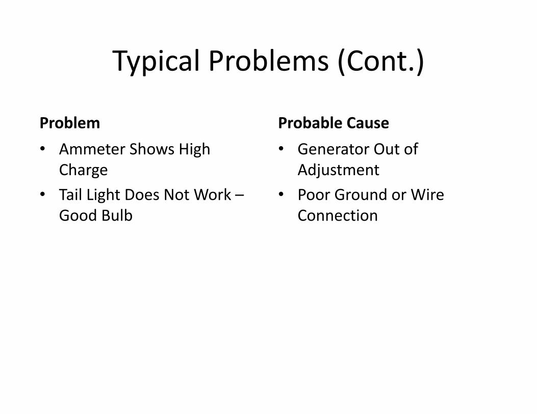
Typical Problems (Cont.)
Problem• Ammeter Shows High
Charge• Tail Light Does Not Work –
Good Bulb
Probable Cause• Generator Out of
Adjustment• Poor Ground or Wire
Connection
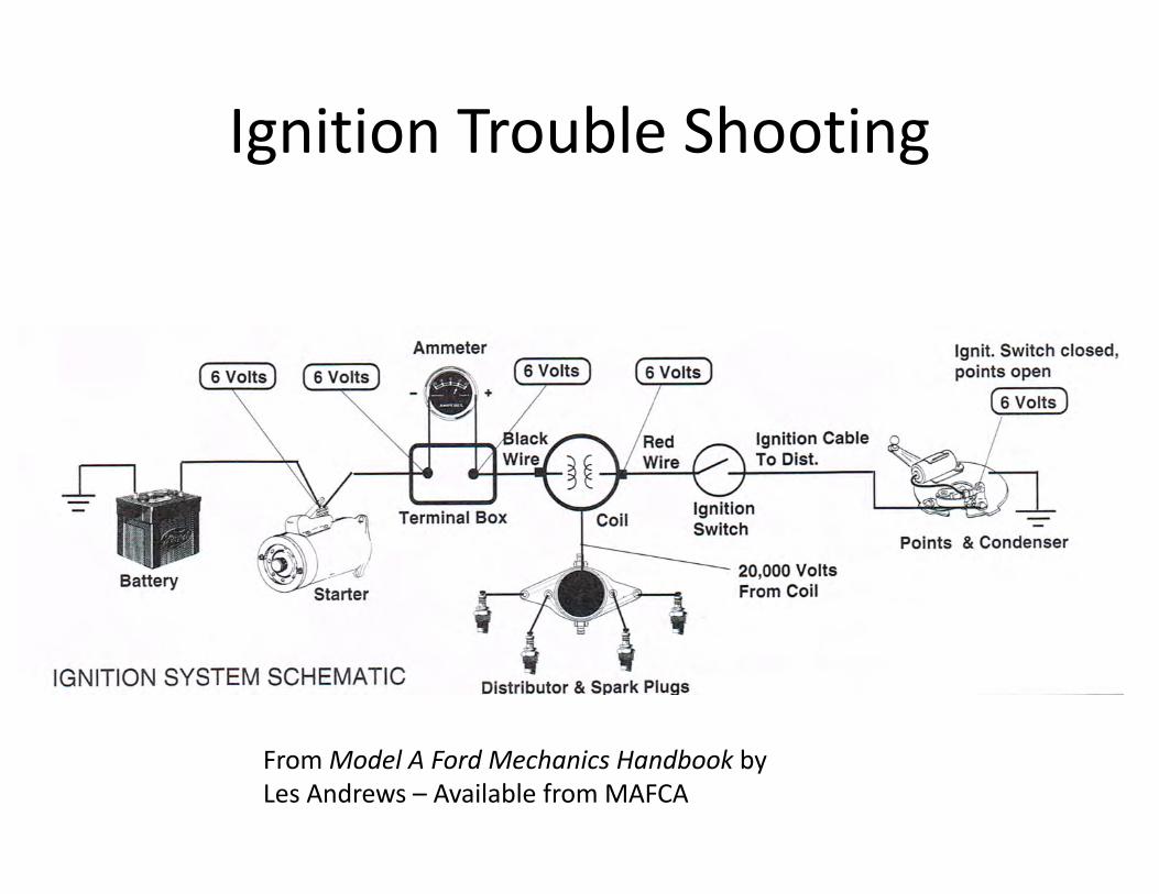
Ignition Trouble Shooting
From Model A Ford Mechanics Handbook by Les Andrews – Available from MAFCA
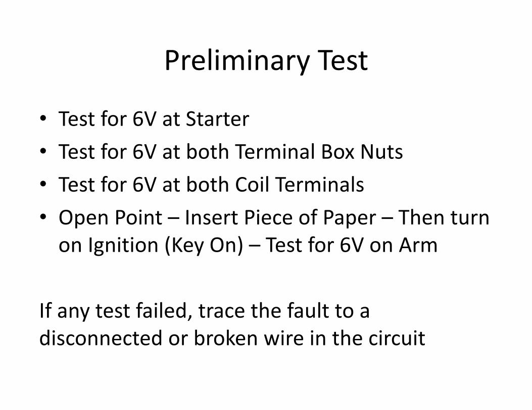
Preliminary Test
• Test for 6V at Starter• Test for 6V at both Terminal Box Nuts• Test for 6V at both Coil Terminals• Open Point – Insert Piece of Paper – Then turn
on Ignition (Key On) – Test for 6V on Arm
If any test failed, trace the fault to a disconnected or broken wire in the circuit


![0jimcotest.com/docs/Archived JIMCO Wiring Repair Connectors.pdf · ii ford ford 2 wire harness kits "6g" series reg., 3 terminal c680 mateswiththis ( • ] alternator - - - regulator](https://static.fdocuments.net/doc/165x107/5b1e1de57f8b9ac0338b484a/jimco-wiring-repair-connectorspdf-ii-ford-ford-2-wire-harness-kits-6g-series.jpg)