Model 922-MES Managed Ethernet Switch - moog.com · range. Figure 1-1: Model 922-MES The following...
40
MOOG PROPRIETARY AND CONFIDENTIAL INFORMATION THIS TECHNICAL DATA/DRAWING/DOCUMENT CONTAINS INFORMATION THAT IS PROPRIETARY TO, AND IS THE EXPRESS PROPERTY OF MOOG INC., OR MOOG INC. SUBSIDIARIES EXCEPT AS EXPRESSLY GRANTED BY CONTRACT OR BY OPERATION OF LAW AND IS RESTRICTED TO USE BY ONLY MOOG EMPLOYEES AND OTHER PERSONS AUTHORIZED IN WRITING BY MOOG OR AS EXPRESSLY GRANTED BY CONTRACT OR BY OPERATION OF LAW. NO PORTION OF THIS DATA/DRAWING/DOCUMENT SHALL BE REPRODUCED OR DISCLOSED OR COPIED OR FURNISHED IN WHOLE OR IN PART TO OTHERS OR USED BY OTHERS FOR ANY PURPOSE WHATSOEVER EXCEPT AS SPECIFICALLY AUTHORIZED IN WRITING BY MOOG INC. OR MOOG INC. SUBSIDIARY. Focal Technologies Corporation A Moog Inc. Company 77 Frazee Avenue Dartmouth, Nova Scotia, Canada B3B 1Z4 Tel: (902) 468-2263 | www.moog.com/marine Model 922-MES Managed Ethernet Switch User Manual Document No.: 922-0662-00 Revision: 1.0 Author(s): A. Cabrera Date of Issue: 2018-01-29
-
Upload
nguyencong -
Category
Documents
-
view
215 -
download
0
Transcript of Model 922-MES Managed Ethernet Switch - moog.com · range. Figure 1-1: Model 922-MES The following...
MOOG PROPRIETARY AND CONFIDENTIAL INFORMATION THIS TECHNICAL DATA/DRAWING/DOCUMENT CONTAINS INFORMATION THAT IS PROPRIETARY TO, AND IS THE EXPRESS PROPERTY OF MOOG INC., OR MOOG INC. SUBSIDIARIES EXCEPT AS EXPRESSLY GRANTED BY CONTRACT OR BY OPERATION OF LAW AND IS RESTRICTED TO USE BY ONLY MOOG EMPLOYEES AND OTHER PERSONS AUTHORIZED IN WRITING BY MOOG OR AS EXPRESSLY GRANTED BY CONTRACT OR BY OPERATION OF LAW. NO PORTION OF THIS DATA/DRAWING/DOCUMENT SHALL BE REPRODUCED OR DISCLOSED OR COPIED OR FURNISHED IN WHOLE OR IN PART TO OTHERS OR USED BY OTHERS FOR ANY PURPOSE WHATSOEVER EXCEPT AS SPECIFICALLY AUTHORIZED IN WRITING BY MOOG INC. OR MOOG INC. SUBSIDIARY.
Focal Technologies Corporation
A Moog Inc. Company 77 Frazee Avenue Dartmouth, Nova Scotia, Canada B3B 1Z4 Tel: (902) 468-2263 | www.moog.com/marine
Model 922-MES
Managed Ethernet Switch
User Manual
Document No.: 922-0662-00 Revision: 1.0
Author(s): A. Cabrera Date of Issue: 2018-01-29

Model 922-MES – User Manual
Focal Technologies Corporation Page ii A Moog Inc. Company Document No. 922-0662-00, Rev 1.0
Document Revision History
Document Revision
Details of Revision Author(s) Date
[yyyy-mm-dd]
Rev. 1 Initial release. ACC 2018-01-29
Reference Documents
Document Number Document Title and Description
922-2005-00 Configuration Drawing: Model 922-MES
922-0408-00 Model 922-MES GUI Software
922-0673-00 MES Core Features Manual
922-0673-01 MES Diagnostics Manual
922-0673-02 MES Diagnostics Protocol Manual

Model 922-MES – User Manual
Focal Technologies Corporation Page iii A Moog Inc. Company Document No. 922-0662-00, Rev 1.0
TABLE OF CONTENTS
1.0 Introduction........................................................................................................................................... 1-1
2.0 Specifications ....................................................................................................................................... 2-1
3.0 Architecture Overview ......................................................................................................................... 3-1
3.1 Example Optical Topologies ......................................................................................................... 3-3
4.0 Configuration ........................................................................................................................................ 4-1
4.1 Factory Default Settings ............................................................................................................... 4-2
4.2 Initial User Setup .......................................................................................................................... 4-4
4.2.1 Initial Card Configuration via Telnet ................................................................................ 4-4
4.2.2 Initial Card Configuration via GUI .................................................................................... 4-5
5.0 Hardware ............................................................................................................................................... 5-1
5.1 Card with Front Panel ................................................................................................................... 5-1
5.2 Card with No Front Panel ............................................................................................................. 5-2
5.3 General Board Handling ............................................................................................................... 5-2
6.0 Connectors and Pin Descriptions ...................................................................................................... 6-1
6.1 Part Locations ............................................................................................................................... 6-1
6.2 Diagnostic LEDs ........................................................................................................................... 6-3
6.3 Jumpers ........................................................................................................................................ 6-3
6.4 Connector Part Numbers .............................................................................................................. 6-4
6.5 96-pin DIN 41612 Backplane Connector (J11) ............................................................................. 6-4
6.6 3.5 mm Jack Factory Diagnostics Port (J3) .................................................................................. 6-5
6.7 LED Connector J5 ........................................................................................................................ 6-5
6.8 Electrical Interfaces ...................................................................................................................... 6-6
6.8.1 +24V Power Input ............................................................................................................ 6-6
6.8.2 Ethernet Interface ............................................................................................................ 6-6
6.8.3 Isolation and Grounding .................................................................................................. 6-7
7.0 Optical Interface ................................................................................................................................... 7-1
7.1 Optical Transceivers and Wavelength .......................................................................................... 7-1
7.2 Optical Fiber ................................................................................................................................. 7-1
7.3 Optical Budget, Range, and Bit Error Rate (BER)........................................................................ 7-2
7.4 Return Loss Tolerance ................................................................................................................. 7-2
7.5 Optical Power ............................................................................................................................... 7-2
7.6 Optical Connectors ....................................................................................................................... 7-3
8.0 Functionality ......................................................................................................................................... 8-1
8.1 Network Settings and Accessibility ............................................................................................... 8-1
8.1.1 IP Address Configuration................................................................................................. 8-1
8.1.2 IP Connectivity ................................................................................................................. 8-1
8.2 Redundancy Configuration ........................................................................................................... 8-2
8.2.1 Media Redundancy Protocol (MRP) ................................................................................ 8-2
8.2.2 Rapid Spanning Tree Protocol (RSTP) ........................................................................... 8-3
8.2.3 HSR/PRP ......................................................................................................................... 8-3
8.3 MES Core Features ...................................................................................................................... 8-3
8.4 System Features .......................................................................................................................... 8-5
8.4.1 Remote Firmware Upgrade ............................................................................................. 8-5
8.4.2 Saving User Switch Configuration ................................................................................... 8-5

Model 922-MES – User Manual
Focal Technologies Corporation Page iv A Moog Inc. Company Document No. 922-0662-00, Rev 1.0
8.4.3 DHCP Enable/Disable ..................................................................................................... 8-5
8.4.4 Software Reset ................................................................................................................ 8-6
8.4.5 Watchdog Reset .............................................................................................................. 8-6
8.4.6 Automatic User Switch Configuration Loading ................................................................ 8-6
8.4.7 UDP Heartbeat Packet .................................................................................................... 8-7
8.4.8 Multiple Modbus Clients .................................................................................................. 8-8
8.4.9 IP Settings for Diagnostics (uC DIAG) ............................................................................ 8-8
9.0 Diagnostics and Control ...................................................................................................................... 9-1
9.1 Modbus TCP/IP ............................................................................................................................ 9-2
9.2 Telnet Interface ............................................................................................................................. 9-2
9.3 Graphical User Interface (GUI) ..................................................................................................... 9-3
LIST OF TABLES Table 2-1: Specifications .................................................................................................................................... 2-1 Table 3-1: MES Core Port Connections ............................................................................................................. 3-2 Table 4-1: MES Core Firmware Options ............................................................................................................ 4-1 Table 4-2: Factory Default Card Configuration Settings (as-built FW 922-1008-00/50) .................................... 4-2 Table 5-1: Card Ordering Part Numbers ............................................................................................................ 5-1 Table 6-1: On-Board Diagnostic LEDs ............................................................................................................... 6-3 Table 6-2: Hardwire Jumper (as-built) ............................................................................................................... 6-3 Table 6-3: Connector/Mating Connector Part Numbers .................................................................................... 6-4 Table 6-4: DIN 41642 (96-pin) Backplane Connector Pin-out ........................................................................... 6-4 Table 8-1: Model 922-MES UDP Heartbeat Packet Content (From uC DIAG) ................................................. 8-7 Table 9-1: Diagnostics Information .................................................................................................................... 9-1
LIST OF FIGURES Figure 1-1: Model 922-MES ............................................................................................................................... 1-1 Figure 3-1: Model 922-MES Ethernet Ports ....................................................................................................... 3-1 Figure 3-2: Model 922-MES Block Diagram and Ports ...................................................................................... 3-1 Figure 3-3: Many sensors transmitting via separate or redundant optical links ................................................. 3-3 Figure 3-4: Multiple Modems Optically Multiplexed onto 1 fiber using CWDM .................................................. 3-3 Figure 3-5: Optical daisy chain of multiple Modems .......................................................................................... 3-4 Figure 5-1: Model 922-MES PCBA with 4HP Front Panel ................................................................................. 5-1 Figure 5-2: Model 922-MES PCBA with No Front Panel ................................................................................... 5-2 Figure 6-1: Model 922-MES Part Locations (Top View) .................................................................................... 6-1 Figure 6-2: Model 922-MES Part Locations (Bottom View) ............................................................................... 6-2 Figure 6-3: DIN 41612 (96-pin) Backplane Connector (Front View) .................................................................. 6-4 Figure 6-4: Power Input Interface Schematic..................................................................................................... 6-6 Figure 6-5: Copper Ethernet Interface Schematic ............................................................................................. 6-6 Figure 6-6: Mounting Holes Locations ............................................................................................................... 6-7 Figure 7-1: LC connector with Standard Boot .................................................................................................... 7-3 Figure 7-2: Tx and Rx ports of an LC-type SFP Transceiver ............................................................................. 7-3 Figure 8-1: Telnet Invalid IP Entry ..................................................................................................................... 8-8 Figure 8-2: Valid IP Entry ................................................................................................................................... 8-8 Figure 8-3: Invalid Subnet Entry ........................................................................................................................ 8-8 Figure 9-1: Telnet Interface Commands ............................................................................................................ 9-2 Figure 9-2: Sample .NET GUI for Modbus TCP Access to Model 922-MES ..................................................... 9-3

Model 922-MES – User Manual
Focal Technologies Corporation Page v A Moog Inc. Company Document No. 922-0662-00, Rev 1.0
ACRONYMS AND ABBREVIATIONS Bidi Bidirectional SFP transceiver
BER Bit Error Rate
CWDM Coarse Wavelength Division Multiplexing
DHCP Dynamic Host Configuration Protocol
DSL Digital Subscriber Line
EEPROM Electrically Erasable Programmable Read-Only Memory
GbE Gigabit Ethernet
GUI Graphical User Interface
IC Integrated Circuit
ICMP Internet Control Message Protocol
IP Internet Protocol
IGMP Internet Group Management Protocol
IWIS Intelligent Well Interface Standardisation
LED Light Emitting Diode
MAC Media Access Control (Ethernet)
MES Managed Ethernet Switch
MTBF Mean Time between Failures
MIB Management Information Base
MRC Media Redundancy Client
MRM Media Redundancy Manager
MRP Media Redundancy Protocol
MTBF Mean Time between Failures
OEM Original Equipment Manufacturer
PCB Printed Circuit Board
PCBA Printed Circuit Board Assembly
PLC Programmable Logic Controller
PLM Power Line Modem
PPP Point-to-Point Protocol
PTP Precision Time Protocol
PRBS Pseudo-Random Bit Sequence
QoS Quality of Service
RSTP Rapid Spanning Tree Protocol
RTU Remote Terminal Unit
SCM Subsea Control Module
SEM Subsea Electronics Module
SELV Safety Extra Low Voltage
SFP Small Form-factor Pluggable (Transceiver)
SHDSL Symmetrical High-Speed Digital Subscriber Line

Model 922-MES – User Manual
Focal Technologies Corporation Page vi A Moog Inc. Company Document No. 922-0662-00, Rev 1.0
SMT Surface Mount Technology
STP Spanning-Tree Protocol or Shielded Twisted Pair (cable)
TCP Transmission Control Protocol
TTL Transistor-Transistor Logic
uC Microcontroller
UDP User Datagram Protocol
VLAN Virtual Local Area Network
WDM Wavelength Division Multiplexer

Model 922-MES – User Manual
Focal Technologies Corporation Page 1-1 A Moog Inc. Company Document No. 922-0662-00, Rev 1.0
1.0 Introduction
A highly reliable managed Ethernet switch is required for use in subsea control networks to provide both copper and optical links for 10/100/1000 Mbps communications using standard open protocols. Focal’s Model 922-MES board is a layer 2 managed Ethernet switch (MES) with ten ports capable of 10/100/1000 Mbps link speeds. Two of these ports can be equipped with small form factor (SFP) transceivers that support Fast (100Base-FX) and Gigabit Ethernet (1000Base-X). The MES provides a configurable managed switch for use in subsea distribution units or Subsea Electronics Modules (SEMs). Interchangeable fiber optic transceivers allow for port configuration as low-power optical links to tie-ins and other subsea nodes or as high-power optical links to the surface via long optical umbilical cables. Complete redundancy can be achieved using multiple cards within a distribution unit or SEM. Redundancy protocols supported by the MES include MRP (Media Redundancy Protocol) and RSTP (Rapid Spanning Tree Protocol). Advanced diagnostics provide real time health monitoring of the system and include optical SFP information, temperature, voltage, current, humidity, Ethernet link status, and Ethernet switch configuration. The MES provides diagnostics access via Telnet and Modbus TCP. Focal’s subsea qualified fiber-optic SFP transceivers are recommended for use with this board. Options available include bidirectional transceivers and CWDM transceivers with support for 50 km, 100 km and up to 200 km range.
Figure 1-1: Model 922-MES
The following features and processes are used to ensure reliability and increase product life:
Conductive cooling and detailed thermal analysis
Advanced diagnostics and health monitoring via Modbus TCP
Use of industrial temperature range electronic components
No fuses, electrolytic or tantalum capacitors
Environmental stress screening
Full qualification testing per API 17F / ISO 13628-6
Traceable components
Use of field-proven electrical and optical components
Design for vibration, shock and EMC

Model 922-MES – User Manual
Focal Technologies Corporation Page 2-1 A Moog Inc. Company Document No. 922-0662-00, Rev 1.0
2.0 Specifications
Table 2-1: Specifications
Ethernet Interfaces (SIIS Level 3)
No. Ports 8 x Copper (via DIN connector) 2 x Optical (via SFP cages)
Protocols 10/100/1000Base-T(X), copper 100Base-FX, 1000Base-X, optical
Protection ESD and transient suppressors (TVS) 500 Vrms isolation
Ethernet Switch Layer 2 Functions
Includes broadcast storm protection, 802.1q VLAN, 802.1p port priority, port mirroring, aging
Time Synchronization
IEEE 1588v2 PTP (E2E) One step end-to-end transparent clock
IP Configuration DHCP with configurable static IP fallback
Diagnostics and Control Parameters
Includes temperature, humidity, voltage, current draw, optical power (Tx/Rx), on time and power off events, Ethernet port status/configuration, MIB counters, card mfr. data (s/n, p/n, F/W revision)
Redundancy RSTP, MRP (manager, client)
Options HSR, PRP
Optical1
Wavelengths 1310 nm and 1550 nm standard CWDM wavelengths (1471 to 1611 nm)
Optical Power Budget
20 to 45 dB, depending on SFP installed
Range 10 to 200 km, depending on SFP installed
Options Bidirectional (single fiber) transceivers
1 See Subsea Qualified SFP Modules datasheet for available optical transceivers.
Connectors
Rear Card Edge 1 x 96-pin DIN 41612 (Ethernet, power)
Front Card Edge 2 x SFP (Ethernet, optical), single or dual LC
Power
Consumption 10 W typical (15 W max.)
Operating Voltage +20 to +28 VDC, regulated input
Rated Current 0.75 A max.
Protection ESD, EMI, over-voltage, reverse voltage, overcurrent (no fuses), 500 Vrms isolation
Mechanical
Dimensions 3U Eurocard, 4 HP, 160 mm x 100 mm
Mounting 3U Eurocard rack or M2.5 hardware
Options Front panel, LED panel, heat plate
Reliability
Design Life > 20 years @ +40 °C
MTBF > 250,000 hrs @ +40 °C
Testing Factory Acceptance Test (FAT) At Tmin and Tmax design temperatures
Qualification ISO 13628-6, API 17F (Q1 Levels) Includes 30 g shock, 5 g vibration
Firmware Update Failsafe remote firmware update
Options Environmental Stress Screening (ESS) Custom qualifications per OEM specification
Environmental
Temperature -18 °C to +70 °C (design and operation) -40 °C to +85 °C (storage)
Humidity 5% to 85 % RH, non-condensing

Model 922-MES – User Manual
Focal Technologies Corporation Page 3-1 A Moog Inc. Company Document No. 922-0662-00, Rev 1.0
3.0 Architecture Overview
The Model 922-MES may be configured with optical links for long distance connections from subsea to surface or long distance optical links (up to 200 km) connecting between subsea nodes. Copper ports support links to short distance (up to 100 m) sensors and PLCs. The 922-MES supports:
Two (2) SFP Ethernet ports for 100BASE-FX / 1000BASE-X operation
Eight (8) Copper Ethernet ports for 10BASE-T /100BASE-TX / 1000BASE-T operation The Ethernet ports and media types available for the MES is shown in the figure below.
Figure 3-1: Model 922-MES Ethernet Ports
The 922-MES PCB has a Eurocard form factor with a 96-pin DIN header at the back for access to eight copper ports (CU1 to CU8) and power. The two SFP transceiver cages at the front provide access to SFP1 and SFP2 ports.
Figure 3-2: Model 922-MES Block Diagram and Ports
MODEL 922MANAGEDETHERNET
SWITCH
(MES)
CU1
CU2
CU3
CU4
CU5
CU6
CU7
CU8
SFP1
SFP2
MEDIA TYPES(COPPER)
10BASE-T
100BASE-TX
1000BASE-T
MEDIA TYPES(OPTICAL)
100BASE-FX
1000BASE-X
SFP
CU1
CU2
CU3
CU4
CU5
CU6
CU7
CU8
SFP1
SFP2
96-P
IN H
EA
DE
R
POWER CIRCUITRY
PH
Ys &
QU
AD
MA
GN
ET
ICS
PH
Ys &
QU
AD
MA
GN
ET
ICS
+24VDC
DIAG-uC
MESCORE
P2
P3
P4
P5
P6
P7
P8
P9
P0
P1
P11
P10

Model 922-MES – User Manual
Focal Technologies Corporation Page 3-2 A Moog Inc. Company Document No. 922-0662-00, Rev 1.0
The MES core chip has the following port connections.
Table 3-1: MES Core Port Connections
Port Connected To Connection Type
P0 SFP1 User-External
P1 SFP2 User-External
P2 CU1 User-External
P3 CU2 User-External
P4 CU3 User-External
P5 CU4 User-External
P6 CU5 User-External
P7 CU6 User-External
P8 CU7 User-External
P9 CU8 User-External
Connection types shown as “User-External” (CU1-8 and SFP1-2) can be changed by the user as required to accommodate system-specific requirements. The user must ensure that any switch configuration changes are valid BEFORE saving it in EEPROM and that communications through all ports is as expected after configuration.

Model 922-MES – User Manual
Focal Technologies Corporation Page 3-3 A Moog Inc. Company Document No. 922-0662-00, Rev 1.0
3.1 Example Optical Topologies The Ethernet switch-based architecture and the configuration adopted for the 922-MES can be used to satisfy a number of different subsea operational requirements. For example, more than one MES Ethernet modem can be used to provide full card redundancy. Alternatively, configuring each card to connect to separate copper Ethernet devices provides additional throughput capacity. Lastly, connecting a copper Ethernet channel between two modems (i.e. electrically daisy-chaining the second card), can provide a second pair of optical connections for other subsea nodes. With RSTP functionality enabled in the MES the copper ports can also be used to electrically daisy chain multiple cards using multiple copper ports. The figures below illustrate some alternative optical topologies supported by this modem.
Figure 3-3: Many sensors transmitting via separate or redundant optical links
Figure 3-4: Multiple Modems Optically Multiplexed onto 1 fiber using CWDM
4x SMFTO SURFACE
ENETSWITCH
TX1
RX1
TX2
RX2
BACKPLANESENSOR 1
SENSOR 2
SENSOR 3
PLC
SERIALSERVER
CAT 5e
CAT 5e
CAT 5e
CAT 5e
1x SMFTO SURFACE
l1, l l l3, 5, 78-CHANNEL
CWDMOPTICALMODULE
NODE 1
ENETSWITCH
TX1
RX1
TX2
RX2
NODE 2
ENETSWITCH
TX1
RX1
TX2
RX2
l1
l2
l3
l4
l5
l6
l7
l8
l2, l l l4, 6, 8

Model 922-MES – User Manual
Focal Technologies Corporation Page 3-4 A Moog Inc. Company Document No. 922-0662-00, Rev 1.0
Figure 3-5: Optical daisy chain of multiple Modems
Configuration and use of the optical and copper ports on the switch are set by a combination of installed optical transceivers and switch register settings. The Ethernet switch settings may be changed from their default settings using a Modbus TCP connection to the MES over any of the 8 copper or 2 optical Ethernet ports.
2x SMF TONEXT NODE
2x SMFTO SURFACE
l1
NODE 1
ENETSWITCH
TX1
RX1
TX2
RX2
NODE 2
ENETSWITCH
TX1
RX1
TX2
RX2NODE 3
ENETSWITCH
TX1
RX1
TX2
RX2
l1
l1
l1
l1
l1
l1
l1

Model 922-MES – User Manual
Focal Technologies Corporation Page 4-1 A Moog Inc. Company Document No. 922-0662-00, Rev 1.0
4.0 Configuration
On power up, the 922-MES starts a boot-up sequence that includes hardware and software initialization of the Ethernet switching functions. This initialization period typically takes about 1.5 minutes and during this time all Ethernet ports are disabled. After this period the switch configuration is loaded from an EEPROM with factory default settings which are listed in section 4.1. These default settings can be changed via any Ethernet port using a Modbus or Telnet connection and also saved to the EEPROM by the user to accommodate specific switch functions and network topologies. MES cards with diagnostics firmware ≥0xA3 support saving the user’s switch configuration to EEPROM via Telnet and Modbus. In addition to the standard boot-up process previously described, cards with uC DIAG FW ≥0xA3 have a second layer verification to ensure the MES core loads its configuration correctly. This layer of verification consists of monitoring the MES core and ensuring the card boots-up correctly on power-up and that the MES core operating system is running correctly. In the unlikely event that a failure is detected such that the MES core cannot access the user EEPROM to load its configuration or the MES core stops responding, the card will attempt to fix the problem on its own by self-rebooting (up to 3 times) and in where needed it will attempt to re-load factory default backup switch configurations depending on the error detected. Note that error codes are embedded in Modbus data and UDP heartbeat packets which are sent automatically by the card every 5 seconds (factory default). The MES card also includes a remote firmware upgrade feature which offers an upgrade path to support future protocols or application specific requirements. The card’s default Ethernet port settings are as follows:
Copper ports CU1-CU8 are 10BASE-T /100BASE-TX / 1000BASE-T with auto-negotiation and auto MDI/MDI-X enabled.
SFP ports SFP1-SFP2 are 1000BASE-X.
Supported packet sizes are standard Ethernet frames (64-1518 bytes), Ethernet II type frame (1536 bytes), huge frames (1916, 2048 bytes) and jumbo frames (9000 bytes).
The configuration options for the card that are saved in non-volatile memory EEPROM include the following:
Ethernet Switch Settings o Link speed, duplex and negotiation mode (per port) o MRP mode (MRM or MRC) for SFP ports SFP1-SFP2. o RSTP for copper ports CU1-CU8 (global)
Diagnostic Settings o Network, IP configuration o DHCP mode o UDP heartbeat frame rate and type o Serial diagnostics
Diagnostic interfaces to the card include Ethernet ports (any copper or SFP) for full diagnostics and control of the board and a factory serial diagnostics interface via a 3.5 mm non-isolated RS-232 port which provides basic read-only card configuration information and board status intended for factory bench testing. The MES card is fully programmed at the factory (core, diagnostics, EEPROMs, etc.). MES core firmware options are shown in the table below. By default the card is shipped with core firmware P/N: 922-1008-50 unless otherwise requested or specified by the customer. The MES card’s diagnostics firmware (uC DIAG) P/N 922-1008-00 is the same for both MES core FW options.
Table 4-1: MES Core Firmware Options
Option MES Core P/N Description Notes
1 922-1008-50 MRP (SFP1-2) + RSTP (CU1-8) As-built. Factory default.
2 922-1008-55 RSTP All Ports (SFP1-2 + CU1-8) Option per customer request.

Model 922-MES – User Manual
Focal Technologies Corporation Page 4-2 A Moog Inc. Company Document No. 922-0662-00, Rev 1.0
4.1 Factory Default Settings The card is shipped from the factory with default configuration settings as shown below and are applicable to MES core FW P/N 922-1008-50 and diagnostics microcontroller FW P/N: 922-1008-00. Settings type marked as “software” mean that they can only be changed via a diagnostics link to the card. Settings type marked as “hardware” mean that they can only be changed via hardware modifications on the board.
Table 4-2: Factory Default Card Configuration Settings (as-built FW 922-1008-00/50)
Name Parameter Default Setting
Ethernet CU1-CU8 (Software)
Link Speed 10BASE-T /100BASE-TX / 1000BASE-T 10BASE-T /100BASE-TX / 1000BASE-T
Duplex Mode Full-Duplex or Half-Duplex Full Duplex
Negotiation Autonegotiation Enabled / Disabled Autonegotiation Enabled
RSTP All ports On / Off On
Ethernet SFP1-SFP2 (Software)
Link Speed 100BASE-FX / 1000BASE-X 1000BASE-X
Duplex Mode Full-Duplex Full Duplex
MRP MRP: On / Off Mode: MRC / MRM
MRP On, MRC mode (client)
Boot up (Hardware)
JP1 Factory Use Only Open
JP2 Open: Normal operation (Internal Flash) Close: uC DIAG code reset (on power-up load from Factory Flash)
Open
JP3 Factory Use Only Shorted
JP4 Factory Use Only Shorted
Diagnostics – uC DIAG (Software)
Network
IP address 192.168.0.100*
Subnet 255.255.255.0
Gateway 192.168.0.254
Primary DNS 194.25.2.129
Secondary DNS 194.25.2.130
DHCP Enable / Disable Enable
Timeout (1-10 min) 5 min.
UDP Heartbeat Format: Short (Normal) / Long Short (Normal)
Interval (1-254) 5 seconds

Model 922-MES – User Manual
Focal Technologies Corporation Page 4-3 A Moog Inc. Company Document No. 922-0662-00, Rev 1.0
Name Parameter Default Setting
Ethernet Switch Settings
On power-up load settings from: (A) EEPROM (user/factory configuration) or (B) Fail-safe factory
Option A
Future Use – Factory Reserved Parameters (Software)
Reserved Network
IP address 192.168.0.201*
Subnet 255.255.255.0
Gateway 192.168.0.1
Primary DNS 194.25.2.129
Secondary DNS 194.25.2.130
Reserved DHCP
Enable / Disable Disable
* Unique IP addresses should be assigned / configured for each MES card used on the same network.

Model 922-MES – User Manual
Focal Technologies Corporation Page 4-4 A Moog Inc. Company Document No. 922-0662-00, Rev 1.0
4.2 Initial User Setup The card is fully operational with factory default settings shown in Table 4-2. The following settings are typically reviewed by the end user and are changed as required depending on the network topology where the card will be used. SFP Port Mode of Operation (redundant or daisy chain):
MRP: ON / OFF
Mode: MRC / MRM Note: In redundant operation (e.g. ring topology) where two MES cards can be connected together using both SFP ports, normally MRP is ON with MRM mode at the surface card and MRP is ON with MRC mode at the subsea card. For daisy chain operation (two SFPs active at the same time) the cards can be left in MRC mode or with MRP OFF.
SFP Media Type (link speed):
100BASE-FX / 1000BASE-X Note: No changes are required for factory-provided SFPs. In cases where the end user installs third party SFPs, changes might be required depending on the SFP type. It is highly recommended to use Focal approved SFPs to ensure reliable performance of the card.
Network Settings:
Diagnostics
Factory reserved parameters Note: Diagnostics is served by a microcontroller (uC DIAG) and provides access to all diagnostic options and management of the card. The factory reserved parameters are intended for future use and could be used by a secondary microcontroller embedded in the MES switch core.
4.2.1 Initial Card Configuration via Telnet 1. Connect a standard Ethernet cable between your PC and CU1 (or any other copper port) of the card under
configuration.
2. Power up the card (+24 VDC). Note: The card boot-up time is about 1.5 minutes and on-board LEDs will indicate a physical link after this period of time. The user can
run continuous pings (IP: 192.168.0.100) to the card as a way to verify once a Telnet link can be established. By default, DHCP is
enabled and this might increase the time between power-up and initial ping responses.
3. Using a terminal emulator program, such as TeraTerm, establish a Telnet connection to the card using:
a. Host: 192.168.0.100
b. TCP Port #: 23
4. The “Model922 MES>” prompt will appear after a connection has been established. At this point Telnet
commands can be used to change and save new user settings. It is recommended to record the new settings
for future reference. Typical configuration options are shown below.
a. SFP port mode of operation. Cfg. Description Telnet Command
1 EEPROM Save: MRP ON in MRC mode save mrp mode mrc
2 EEPROM Save: MRP ON in MRM mode save mrp mode mrm
3 EEPROM Save: MRP OFF save mrp mode off
b. SFP media type.
Cfg. Description Telnet Command
1a EEPROM Save: SFP 1 set for 1000BASE-X save sfp mode sfp1 1000
1b EEPROM Save: SFP 2 set for 1000BASE-X save sfp mode sfp2 1000
2a EEPROM Save: SFP 1 set for 100BASE-FX save sfp mode sfp1 100
2b EEPROM Save: SFP 1 set for 100BASE-FX save sfp mode sfp2 100
c. Network settings.
Cfg. Description Telnet Command
1 EEPROM Save: uC DIAG IP
(e.g. IP = 192.168.0.100)
set ip 192.168.0.100
2 EEPROM Save: SW Core IP
(e.g. IP = 192.168.0.201)
set fpga ip 192.168.0.201
Note: For a complete list of available telnet commands refer to the “Telnet Interface” section of this document.
5. Power cycle the card for all changes to take effect.

Model 922-MES – User Manual
Focal Technologies Corporation Page 4-5 A Moog Inc. Company Document No. 922-0662-00, Rev 1.0
4.2.2 Initial Card Configuration via GUI
MES cards with diagnostics FW 922-1008-00 (uC DIAG) version ≥ 0xA4 can be configured using Focal’s sample 922-MES GUI P/N 922-0408-00. More details of the GUI are shown in the “Graphical User Interface (GUI)” section of this document. The card configuration procedure using the GUI is similar to the Telnet procedure. However, when using the GUI the user should following steps. 1. Connect a standard Ethernet cable between your PC and CU1 (or any other copper port) of the card under
configuration.
2. Power up the card (+24 VDC).
3. Run the 922-MES GUI and follow the steps below in sequential order:
a. Add a new card configuration by clicking the top left corner “+” button (default factory diagnostics IP
address is 192.168.0.100).
b. Click the “Connect” button.
c. Click System Maintenance Boot Config Open Boot Config Editor. The “Model 922 Boot Config
Editor” window will appear.
d. Make the desired card configuration changes. E.g. SFP settings, MRP (if available), RSTP changes,
etc.
Note that in the “Model 922 Config Editor” window, changes made by the user will only take effect after
the “Save Configuration” button is pressed and after one subsequent power cycle.
To make experimental volatile changes (not saved in EEPROM) the “Ethernet Switch Settings” section
of the GUI should be used.
e. Click the “Save Configuration” button to save the new card settings to EEPROM.
f. Power-cycle one (1) time ONLY the card under configuration.
g. Wait for GUI reconnection.
h. Verify the card’s functionality and that the changes are as expected.
i. A GUI message will appear asking the user to confirm if the changes are ok.
i. If the user accepts the changes then the card will keep the new user configuration.
ii. If the user ignores the changes and does not confirm the changes via the GUI then the card will
revert to the last known configuration on the next power-cycle.
4. Change the diagnostics IP address via Telnet (if required) following the steps shown in the previous section
4.2.1 step 4c.
5. Power cycle the card for the changes to take effect.
6. (Optional) Reconnect with the GUI and then re-open the “Model 922 Boot Config Editor” window and click
“Export Configuration” to save a copy of the new user configuration to your local PC.
7. Done! The initial card configuration is completed.

Model 922-MES – User Manual
Focal Technologies Corporation Page 5-1 A Moog Inc. Company Document No. 922-0662-00, Rev 1.0
5.0 Hardware
The 922-MES can be ordered using the card level part numbers shown in the table below. Refer to configuration drawing 922-2005-00 for more details.
Table 5-1: Card Ordering Part Numbers
Card P/N Description Configuration Drawing
922-5012-97 Managed Ethernet Switch (MES), No SFPs, 6HP Front Panel, DIN Code Strip
922-2005-00
922-5012-98 Managed Ethernet Switch (MES), No SFPs, 4HP Front Panel 922-2005-00
922-5012-99 Managed Ethernet Switch (MES), No SFPs, No Front Panel 922-2005-00
The 922-5012-xx cards include a 922-0208-00 PCB assembly (PCBA) which is a standard 3U Eurocard form factor of 100 mm x 160 mm. This PCBA is designed for interfacing with a custom backplane in a Eurocard sub-rack (card cage) or wiring harness using a 96-pin DIN 41612 connector. This connector provides the interface for power and eight (8) copper Ethernet ports. On the front of the PCBA are two (2) SFP ports and a factory diagnostics port. Key part locations are shown in section 6.1.
5.1 Card with Front Panel Card P/N: 922-5012-98
This card includes a 4 HP front panel as shown in the figure below. This card will fit in a 4 HP wide slot (0.8 in or 20.32 mm) in a 3U Eurocard sub-rack. The front panel covers the front end of the PCBA and includes a handle to allow for ESD safe handling and installation via rack card guides. Front panel cutouts allow access to the SFP ports and a factory diagnostics port. This PCBA also includes a heat plate for improved conductive heat dissipation. The 922-5012-97 PCBA includes a code strip which is installed on the DIN connector and a 6HP front panel (1.2 in or 30.48 mm). Note that SFPs are not included in the card assembly.
Figure 5-1: Model 922-MES PCBA with 4HP Front Panel

Model 922-MES – User Manual
Focal Technologies Corporation Page 5-2 A Moog Inc. Company Document No. 922-0662-00, Rev 1.0
5.2 Card with No Front Panel Card P/N: 922-5012-99
This card does not include a front panel and is intended for bolt down installation on a metal plate, in which case a dedicated wiring harness is needed for connection to the DIN header. Top and front views of this card are shown in the figure below.
Figure 5-2: Model 922-MES PCBA with No Front Panel
5.3 General Board Handling The 922-MES PCBA does not require forced air convective cooling. Generally heat from the card is conducted through the mounting hardware, such as metal standoffs, or via the front panel to rack connections. If the card
is intended to be used for extended periods beyond +40 C ambient, other heat dissipation or heatsink options should be considered to extended product life. Contact the factory for more information. Care must always be taken during the handling of PCBAs to ensure product integrity. The following guidelines should be adhered to in working with PCBAs:
Always handle boards by the edges and do not touch any connector pins or other exposed interface contacts.
Handle boards at an ESD safe workstation with a clean surface. Maintain ESD precautions during installation.
Store each card in a separate, ESD protective package.
Do not flex boards during handling or when mounted. The mounting surface needs to be flat and even such that the board is not flexed when bolted down.
Do not cause unnecessary shock and vibration, such as dropping or rough handling of the boards.

Model 922-MES – User Manual
Focal Technologies Corporation Page 6-1 A Moog Inc. Company Document No. 922-0662-00, Rev 1.0
6.0 Connectors and Pin Descriptions
6.1 Part Locations Refer to the figure below for location of connectors, hard wired jumpers and on-board diagnostic LEDs on the card. Note some factory testing headers and jumpers may not be exactly as shown.
REF. DESCRIPTION
SFP1-2 SFP CAGES (ETHERNET SFP1-2)
JP2 uC DIAG CODE RESET
J3
FACTORY DIAGNOSTICS CONNECTOR (RS-232)
J5 LED HEADER (I2C)
J11
DIN 41612 BACKPLANE 96-PIN CONNECTOR (POWER AND ETHERNET CU1-8)
D2-3, D5-9,
D12-27 DIAGNOSTIC LEDS
M17 SENSOR (TEMP. AND HUMIDITY)
J10 EXPANSION CONN. (FUTURE USE)
J4/6/7/9 JP1/3/4
FACTORY USE
Figure 6-1: Model 922-MES Part Locations (Top View)
J4 SFP1 SFP2
JP2
JP3
JP1
J5
JP4
J10
D5 - D9
D12 - D27
J3
D2 D3
J6
J9 M17
J7
J11

Model 922-MES – User Manual
Focal Technologies Corporation Page 6-2 A Moog Inc. Company Document No. 922-0662-00, Rev 1.0
The 922-MES card has three (3) unique MAC addresses used for diagnostics (MAC-UC) and Ethernet switching functions (MAC-PS and MAC-PL). The location of the serial number and MAC addresses labels are shown in the figure below.
Figure 6-2: Model 922-MES Part Locations (Bottom View)
S/N
MAC-PL MAC-UC
MAC-PS

Model 922-MES – User Manual
Focal Technologies Corporation Page 6-3 A Moog Inc. Company Document No. 922-0662-00, Rev 1.0
6.2 Diagnostic LEDs The table below describes the on-board diagnostic LEDs on the card. LEDs are intended for bench level verification as typical status from installed equipment is accessed via Ethernet.
Table 6-1: On-Board Diagnostic LEDs
LED LED Name Note
D2 SFP2 LOS 1
D3 SFP1 LOS 1
D5 POWER 2
D6 SFP1 LINK 3
D7 SFP1 ACTIVITY 4
D8 CU1 LINK 3
D9 CU1 ACTIVITY 4
D12 SFP2 LINK 3
D13 SFP2 ACTIVITY 4
D14 CU2 LINK 3
D15 CU2 ACTIVITY 4
D16 CU3 LINK 3
D17 CU3 ACTIVITY 4
D18 CU4 LINK 3
D19 CU4 ACTIVITY 4
D20 CU5 LINK 3
D21 CU5 ACTIVITY 4
D22 CU6 LINK 3
D23 CU6 ACTIVITY 4
D24 CU7 LINK 3
D25 CU7 ACTIVITY 4
D26 CU8 LINK 3
D27 CU8 ACTIVITY 4
Notes: 1. Green: ON Solid = No loss of optical signal (No LOS). OFF = Loss of optical signal (LOS) 2. Green: ON Solid = Board is ON. OFF = Board is OFF. 3. Yellow: ON Solid = Ethernet Link Up. OFF = No Ethernet Link 4. Green: ON Solid = Ethernet Link Up. Blinking = Ethernet TX/RX Activity. OFF = No Ethernet Link.
6.3 Jumpers The table below describes the hardware jumpers on the card.
Table 6-2: Hardwire Jumper (as-built)
Jumper Name Note
JP1 FACTORY USE OPEN: Default
JP2 uC DIAG
CODE RESET
This jumper is only checked by the software on power up. OPEN (default): Diagnostics uC runs in normal operation. SHORTED: Revert uC DIAG firmware to factory version.
JP3 FACTORY USE SHORTED: Default
JP4 FACTORY USE SHORTED: Default
D16
D5
D7
D9
D17
D18
D19
D20
D21
D22
D23
D24
D25
D26
D27
D13
D15
D6
D8
D12
D14
D2 D3

Model 922-MES – User Manual
Focal Technologies Corporation Page 6-4 A Moog Inc. Company Document No. 922-0662-00, Rev 1.0
6.4 Connector Part Numbers The 922-MES connectors and their mating connector part number is shown below.
Table 6-3: Connector/Mating Connector Part Numbers
On-board Connector Mating Connector
Ref Description Manufacturer Manufacturer Part Number Manufacturer Part Number
J11 96-Pin DIN 41612 Harting 0903-196-6921 09032966824 (Vert. PCB Mount)
J3 3.5 mm Stereo Jack CUI Inc. SJ1-3523NG SP-3501
6.5 96-pin DIN 41612 Backplane Connector (J11) A 96-pin DIN 41612 backplane connector provides access to eight (8) copper ports (CU1-CU8) and power interface.
Figure 6-3: DIN 41612 (96-pin) Backplane Connector (Front View)
Table 6-4: DIN 41642 (96-pin) Backplane Connector Pin-out
Pin Name
Row A Row B Row C
1 DA+_CU1 REF_CU1 DB+_CU1
2 DA-_CU1 REF_CU1 DB-_CU1
3 DC+_CU1 DB+_CU5 DD+_CU1
4 DC-_CU1 DB-_CU5 DD-_CU1
5 DA+_CU5 DC+_CU5 DD+_CU5
6 DA-_CU5 DC-_CU5 DD-_CU5
7 VIN1+ VIN1+ VIN1+
8 VIN2+ VIN2+ VIN2+
9 DC-_CU2 DC+_CU2 REF_CU5
10 VIN- VIN- VIN-
11 VIN- VIN- VIN-
12 DD+_CU2 DD-_CU2 REF_CU5
13 DA+_CU2 DB+_CU2 REF_CU2
14 DA-_CU2 DB-_CU2 REF_CU2
15 DA+_CU3 DB+_CU3 REF_CU3
16 DA-_CU3 DB-_CU3 REF_CU3
17 DA+_CU6 DD+_CU3 DC+_CU3
18 DA-_CU6 DD-_CU3 DC-_CU3
19 DC+_CU6 DB+_CU6 REF_CU6
20 DC-_CU6 DB-_CU6 REF_CU6
21 DA+_CU7 DB+_CU7 DD+_CU6
22 DA-_CU7 DB-_CU7 DD-_CU6
23 DC+_CU7 REF_CU7 DD+_CU7
24 DC-_CU7 REF_CU7 DD-_CU7
25 DA+_CU8 DB+_CU8 DD+_CU8
26 DA-_CU8 DB-_CU8 DD-_CU8
27 DC+_CU8 DC+_CU4 REF_CU8
28 DC-_CU8 DC-_CU4 REF_CU8
29 DA+_CU4 DB+_CU4 REF_CU4
30 NC NC DD+_CU4
31 DA-_CU4 DB-_CU4 REF_CU4
32 NC NC DD-_CU4
Notes: 1. NC = No Connect 2. VIN1+ (24V INPUT1+) and VIN2+ (24V INPUT2+) are independent power inputs, each with reverse protection diodes and can be
connected to separate power supplies or both from one power supply.
C
B
A
132

Model 922-MES – User Manual
Focal Technologies Corporation Page 6-5 A Moog Inc. Company Document No. 922-0662-00, Rev 1.0
6.6 3.5 mm Jack Factory Diagnostics Port (J3) The factory diagnostics port (J3) shown in Figure 6-1 is an RS-232 serial port. This port is non-isolated and it is intended for bench testing and factory debugging purposes only. This port outputs basic diagnostic information on power-up which includes network settings, MAC addresses and other configurations of the card. The signal levels on this port are compatible with RS-232 levels and can be directly connected to a PC or other terminal device for bench testing and debugging purposes. This port is an output only and writing to this port is not supported and will have no effect.
CAUTION
This RS-232 serial diagnostics port is non-isolated and it is intended for bench testing and factory debugging purposes only. This port is not intended for final installations.
When serial diagnostics is enabled a continuous stream of hexadecimal data separated by commas is sent via the serial port. By default serial diagnostics is disabled and Telnet commands can be used to enable or disable this function. Note: For more information on the use of this interface please contact the factory.
6.7 LED Connector J5 The 922-MES card has the capability of driving an array of external LEDs on a PCBA via a connection to J5. Typically this configuration is used on the topside card with a front panel that includes an LED PCBA. Contact factory for details and options.

Model 922-MES – User Manual
Focal Technologies Corporation Page 6-6 A Moog Inc. Company Document No. 922-0662-00, Rev 1.0
6.8 Electrical Interfaces This section shows the schematics of the user accessible interface circuits, which are the +24V power input and copper Ethernet interfaces.
6.8.1 +24V Power Input The power input interface schematic in the figure below shows the input protection diodes, common mode EMC filter and DC-DC converter. Power input must be within +20VDC to +28VDC. Ideal input voltage is +24VDC and provided by a supply with a Safety Extra Low Voltage (SELV) rating. See section 2.0 for specification details.
Figure 6-4: Power Input Interface Schematic
6.8.2 Ethernet Interface The Ethernet interface schematic shown in the figure below, is identical for all Ethernet copper ports. This schematic shows the transformer isolation, REF (shield), and termination used.
Figure 6-5: Copper Ethernet Interface Schematic
Model 922-MES – User Manual
Focal Technologies Corporation Page 6-7 A Moog Inc. Company Document No. 922-0662-00, Rev 1.0
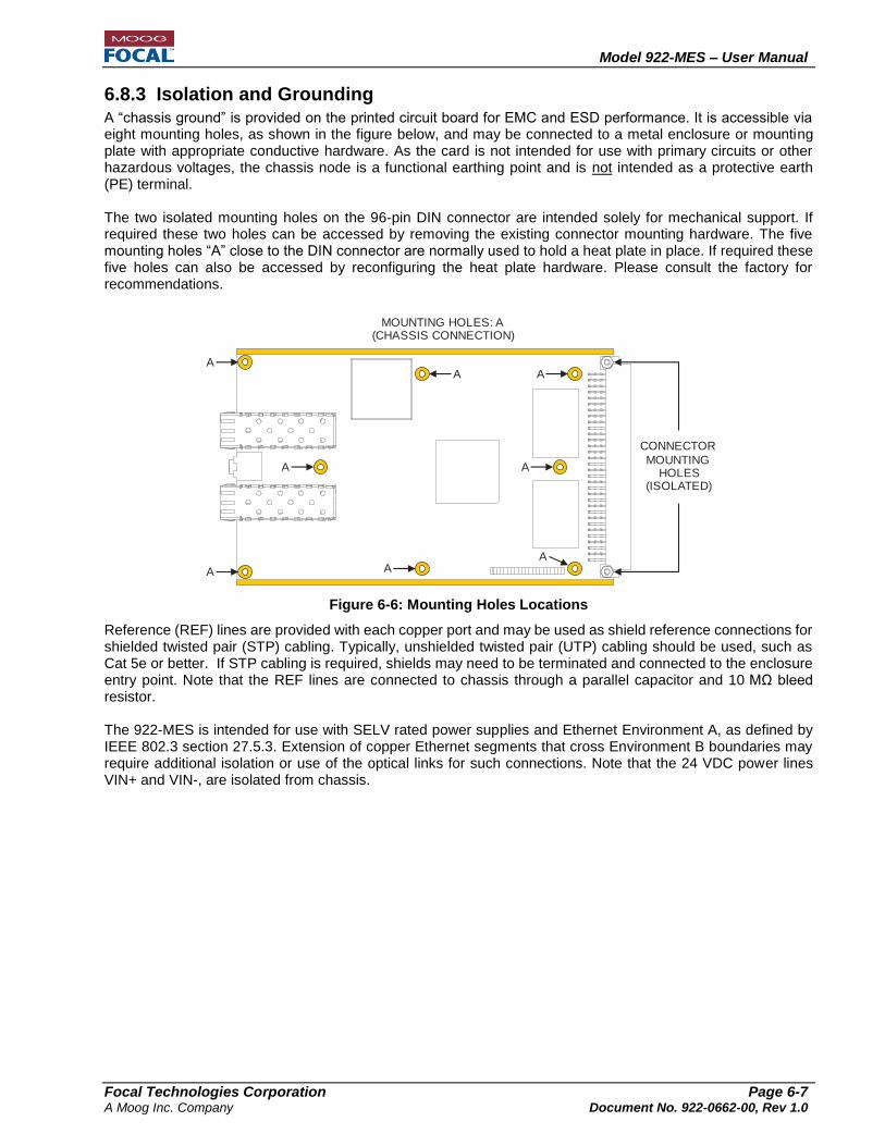
6.8.3 Isolation and Grounding
A “chassis ground” is provided on the printed circuit board for EMC and ESD performance. It is accessible via eight mounting holes, as shown in the figure below, and may be connected to a metal enclosure or mounting plate with appropriate conductive hardware. As the card is not intended for use with primary circuits or other hazardous voltages, the chassis node is a functional earthing point and is not intended as a protective earth (PE) terminal. The two isolated mounting holes on the 96-pin DIN connector are intended solely for mechanical support. If required these two holes can be accessed by removing the existing connector mounting hardware. The five mounting holes “A” close to the DIN connector are normally used to hold a heat plate in place. If required these five holes can also be accessed by reconfiguring the heat plate hardware. Please consult the factory for recommendations.
Figure 6-6: Mounting Holes Locations
Reference (REF) lines are provided with each copper port and may be used as shield reference connections for shielded twisted pair (STP) cabling. Typically, unshielded twisted pair (UTP) cabling should be used, such as Cat 5e or better. If STP cabling is required, shields may need to be terminated and connected to the enclosure entry point. Note that the REF lines are connected to chassis through a parallel capacitor and 10 MΩ bleed resistor. The 922-MES is intended for use with SELV rated power supplies and Ethernet Environment A, as defined by IEEE 802.3 section 27.5.3. Extension of copper Ethernet segments that cross Environment B boundaries may require additional isolation or use of the optical links for such connections. Note that the 24 VDC power lines VIN+ and VIN-, are isolated from chassis.
MOUNTING HOLES: A(CHASSIS CONNECTION)
A
A
A A
A
AA
A
CONNECTOR
MOUNTINGHOLES
(ISOLATED)

Model 922-MES – User Manual
Focal Technologies Corporation Page 7-1 A Moog Inc. Company Document No. 922-0662-00, Rev 1.0
7.0 Optical Interface
7.1 Optical Transceivers and Wavelength The Model 922-MES card communicates optically using one or two small form-factor pluggable (SFP) transceivers per card. The device can be ordered with a wide selection of qualified SFPs, depending on the application distance, optical budget, and fiber count requirements. Depending on the SFPs selected, the card is able to function on one (1) to four (4) fibers. The MES supports SFPs with 100 Mb/s and 1 Gb/s optical data rates. In general, lower optical data rates have higher optical power budget and longer range. Standard, API qualified, SFPs utilize two separate fibers, typically one transmitting in each direction at 1310 nm for shorter links (< 50 km), or 1550 nm for longer links, up to 200 km at 100 Mb/s. Bidirectional SFPs, or “Bidis”, are available with integrated wavelength division multiplexing (WDM) optical components, providing bidirectional operation using two wavelengths on a single fiber (e.g. 1550/1490 nm or 1310/1550 nm). Bidi SFPs are typically limited to a range of 50 km. SFP transceivers with CWDM wavelengths (1471 nm to 1611 nm) may be used to combine up to four sets of modems (i.e. 8 CWDM wavelengths) on the same fiber. CWDM systems require additional optical modules that may include power splitters, for redundancy, and/or CWDM couplers for combining or separating wavelengths. Optical modules are available from the factory in a variety of packaging options. Note that the combination of multiple wavelengths on a single fiber may cause the combined optical power levels to exceed Class I power limits. Typical 1 Gb/s SFP options include a Bidi version (1550/1490 nm) with 50 km range and a CWDM version (1551 nm) with 100 km range. Contact the factory for qualified SFP options and for instructions on installation.
7.2 Optical Fiber The card communicates using up to two SFP transceivers per card, which requires up to four fibers. The fiber must be singlemode, such as SMF-28e (9/125 μm) or equivalent. For links over 100 km, dispersion shifted singlemode fiber (SMF-DS), should be considered to minimize dispersion on the 1550 nm wavelength. Bend-insensitive jumpers with reduced boot-lengths may be used to allow for fiber routing to the card within confined spaces, such as in subsea pressure housings. These jumpers are available from the factory or third party vendors. Regardless of the fiber types used, the following handling guidelines should be followed:
Observe the bend radius of fiber optic cables at all times When mounting, disassembling, or reassembling the cards, ensure that no fibers are subjected to bends in excess of those held by the natural routing of the fibers. The minimum bend radius of standard singlemode SMF-28e fibers should generally be no less than 25 mm, though single loops may be less than this – as low as 15 mm – without damaging the fibers. Keep in mind that allowable values are dependent on the type of fiber and the environment, and cable manufacturers typically specify the minimum bend radius. Avoid even temporary bends with a radius less than 15 mm, which may induce cracks that affect long-term reliability of the fibers. Use bend insensitive fibers where tight bends are expected during installation or operation. Ensure fiber optic components are of the same type
All jumpers, cables, connectors, couplers, and Fiber Optic Rotary Joints (FORJs) used in the external optical system connecting the card must use the same type of fiber, i.e. all components in the fiber link should be singlemode. A single mismatched jumper in the system may cause intermittent or persistent optical link errors. Do not rely on cable jacket or connector colors alone to determine the type of optical fiber.

Model 922-MES – User Manual
Focal Technologies Corporation Page 7-2 A Moog Inc. Company Document No. 922-0662-00, Rev 1.0
7.3 Optical Budget, Range, and Bit Error Rate (BER) A variety of approved and tested SFP transceivers are available from Focal Technologies for maximum distances from 10 km to 200 km. The optical power budget is dependent upon the SFPs selected, but typically varies from 16 dB to 45 dB with an optical bit error rate (BER) of 1 x 10-12. Contact the factory for the current list of available, API qualified transceivers. Optical receivers will experience errors if the received optical power is too low (i.e. below the receive sensitivity of the photo detector). Ensure the total optical losses of the components in the external cable system (jumpers, cables, connectors, couplers, etc.) are less than the specified optical power budget of the SFP combination used. For detailed measurements or trouble-shooting, a calibrated optical power meter is recommended.
Optical receivers can also saturate and experience errors if the received optical power is too high. This is more likely to occur (especially in a lab environment) when using high power transceivers. Use a 5 or 10 dB fixed attenuator in line with each fiber during bench tests or with short, low loss links to ensure a minimum level of attenuation is present. A variable optical attenuator (VOAT) can be used for simulating system losses or testing the maximum insertion loss supported. In some high power systems, receivers can actually be damaged by excessive optical power, so a fixed attenuator is recommended even when using a VOAT to ensure a minimum attenuation at all times. Adding attenuators for bench testing simulates only the insertion loss of a field system. Dispersion effects are not simulated with attenuators and should be verified with spools of test fiber matching the length of the system being designed. Dispersion effects con incur a power penalty of 1-2 dB. Please contact the factory for assistance with optical system analysis and recommendations.
7.4 Return Loss Tolerance The optical system external to the card should have a minimum of 20 dB return loss. Excessive optical reflections may degrade optical budget and/or reduce transceiver lifetime. For systems with bidirectional optical transmission on a single fiber, sufficient reflected optical power on one wavelength can interfere with received power on another wavelength and cause data errors. Return loss specifications for systems with WDM or CWDM couplers must be determined based on a more detailed analysis of the maximum link attenuation, optical levels, and filter characteristics, but typically 25-30 dB return loss is sufficient to ensure reflected optical power does not cause link errors.
7.5 Optical Power All optical power levels are within Class I limits (eye-safe), however as general safe practice, fiber connectors should not be held close to the eye for inspection. Note that all of the SFP optical wavelengths used for Model 922 links are infrared and not visible, even at high power levels.
Active optical outputs should NEVER be viewed with a magnifying device of any kind (e.g. fiber microscope). Always turn off all transmitters before inspecting fibers, optical connectors, or optical bushings.

Model 922-MES – User Manual
Focal Technologies Corporation Page 7-3 A Moog Inc. Company Document No. 922-0662-00, Rev 1.0
7.6 Optical Connectors Optical connectors for the SFPs qualified for use with the 922-MES are LC type. The mating connector for the LC interface, with a standard boot, is shown in the figure below. Ruggedized (metal) LC compatible connectors, such as the Molex LC2+ and Diamond F3000, can also be used.
Figure 7-1: LC connector with Standard Boot
Standard SFP optical transceivers typically have a transmit and receive optical bushing (LC type) for dual fiber operation. The transmit side (Tx) and the receiver side (Rx) of an SFP is shown below.
Figure 7-2: Tx and Rx ports of an LC-type SFP Transceiver
Optical Connectors Care:
It is critical to ensure all fiber connectors are clean and free of dirt and debris. Even a small amount of dirt or fluid contaminant may degrade link performance, and most reported optical link problems are due simply to poor or contaminated optical connections.
Keep protective dust covers on fiber connectors and bushings when not in use.
Do not touch the white ceramic ferrules of the connectors with bare hands or objects other than cleaning materials.
Prior to making a fiber connection, clean the barrel and tip of the ferrule using a suitable solvent, such as reagent grade isopropyl alcohol, and a lint-free optics cleaning tissue, such as Kimwipes® EX-L. Carefully dab any dirt or debris off the face of the ceramic ferrules. Excessive dirt may need to be cleared with pressurized air from a can prior to wiping the ferrule to avoid scratching the fiber itself. Do not used air from a compressor as it may be contaminated with oil.
During mating or un-mating of fiber connectors with bushings, keep the connector aligned as straight as possible. Avoid side loading the ceramic ferrule, which can crack the internal alignment sleeve in the bushing.
Each fiber connector should be inspected with a handheld fiber microscope prior to final assembly to ensure there are no scratches, pits, debris, or fluid contamination on the fiber face. Ensure connectors do not have any optical power present prior to inspection, e.g. with a handheld power meter.
Ferrule
Tx
(Optical
Output)
Rx
(Optical
Input)

Model 922-MES – User Manual
Focal Technologies Corporation Page 8-1 A Moog Inc. Company Document No. 922-0662-00, Rev 1.0
8.0 Functionality
The Model 922-MES is a layer 2 managed Ethernet switch (MES) implemented in a fully reconfigurable FPGA-based platform, including DDR3 memory and two microcontrollers to enable many existing and future protocols, as well as application specific code. The MES provides access to ten Ethernet ports capable of 10/100/1000 Mbps link speeds. Two of these ports can be equipped with small form factor (SFP) transceivers that support Fast Ethernet (100Base-FX) and Gigabit Ethernet (1000Base-X). Redundancy protocols supported by the MES include MRP (via two SFP ports) and RSTP (via eight copper ports). Additional redundancy protocols can be supported, e.g. HSR/PRP. Please contact the factory for availability. Ethernet ports are configured manually or through autonegotiation for 10/100/1000M operation on copper ports and manually for 100/1000M for SFP ports. The card also provides support for advanced timing protocols, such as IEEE 1588v2 (PTP), which is critical for synchronization in many sensor applications. A range of subsea-qualified, pluggable, fiber-optic transceivers enables many optical topologies, including dual fiber mode and bidirectional operation with up to 16 wavelengths on a single fiber using CWDM (Coarse Wavelength Division Multiplexing) technology. Fiber umbilicals of up to 200 km length are supported. The Model 922-MES GUI software (P/N 922-0408-00) provides advanced diagnostics via Modbus TCP for real-time health monitoring of the system as well as easy configuration of all interfaces and modes of operation. A proven RTOS (Real Time Operating System) and remote firmware upgrade feature increase system reliability while offering an upgrade path for future protocols or application specific requirements.
8.1 Network Settings and Accessibility
8.1.1 IP Address Configuration
Each 922-MES board is assigned with three unique MAC addresses during factory configuration. The MAC addresses are marked on the board, as shown in Figure 6-2, and recorded at the factory with cross-reference to serial number, and thereby customer order, should it ever need to be retrieved. There are two IP addresses (diagnostics and factory-reserved) for the MES. The diagnostics IP can be assigned statically or dynamically using DHCP. Either mode can be enabled remotely using a virtual Telnet terminal over any Ethernet port, followed by powering cycling the board after the changes has been submitted to the card. The diagnostics IP address provides full diagnostics and control of the card and is served by a master microcontroller (uC DIAG). The factory-reserved IP address is intended for future use and is normally static and it is setup by the user on initial card configuration. By factory default, the MES card obtains its diagnostics IP address using DHCP (i.e. dynamic IP allocation), configured with a 5 min. timeout. If the connecting network does not support DHCP to provide a dynamic IP within this time frame, the card will automatically revert to use its locally stored (static) IP address and network settings. Factory default network parameters are shown in Table 4-2.
8.1.2 IP Connectivity The MES hosts the following simultaneous IP connections:
Up to four Modbus TCP clients over any Ethernet port, including ‘remotely’ (i.e. from surface card) via the optical ports. The Modbus TCP connection provides diagnostics information, which can be accessed using Modbus software (e.g. ModScan or sample 922-MES GUI).
One Telnet over any Ethernet port, including ‘remotely’ via the optical ports. Typically used for initial card configuration (e.g. redundant operation mode of and network settings), basic card diagnostics and link status information for copper and SFP ports.
Model 922-MES – User Manual
Focal Technologies Corporation Page 8-2 A Moog Inc. Company Document No. 922-0662-00, Rev 1.0
8.2 Redundancy Configuration The redundancy protocols supported by the 922-MES are presented in the following subsections.
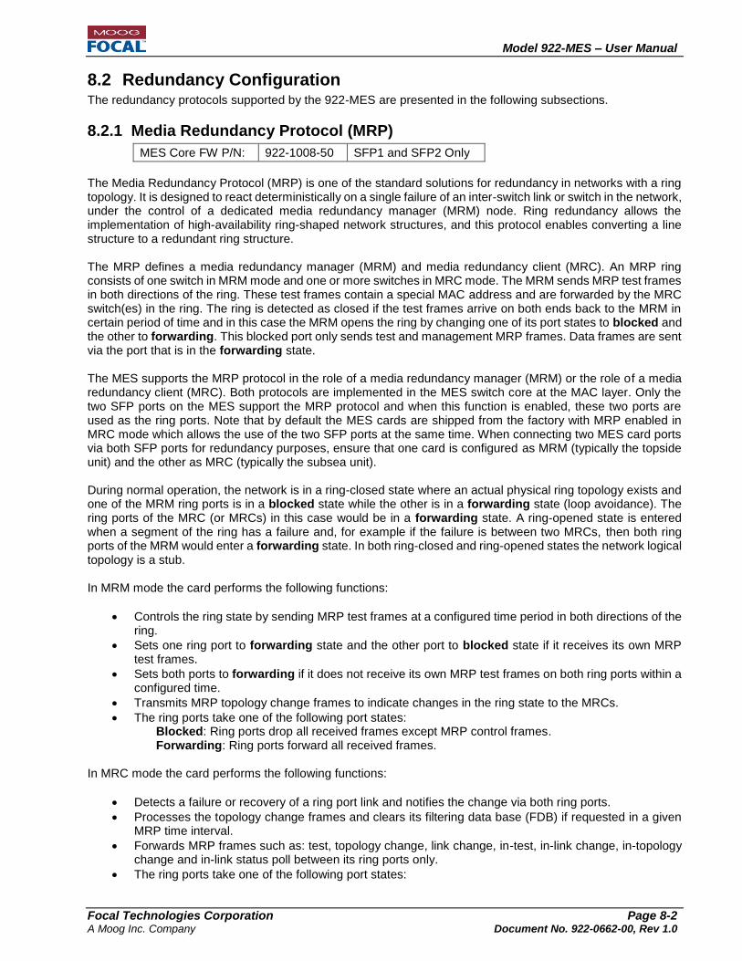
8.2.1 Media Redundancy Protocol (MRP)
MES Core FW P/N: 922-1008-50 SFP1 and SFP2 Only
The Media Redundancy Protocol (MRP) is one of the standard solutions for redundancy in networks with a ring topology. It is designed to react deterministically on a single failure of an inter-switch link or switch in the network, under the control of a dedicated media redundancy manager (MRM) node. Ring redundancy allows the implementation of high-availability ring-shaped network structures, and this protocol enables converting a line structure to a redundant ring structure. The MRP defines a media redundancy manager (MRM) and media redundancy client (MRC). An MRP ring consists of one switch in MRM mode and one or more switches in MRC mode. The MRM sends MRP test frames in both directions of the ring. These test frames contain a special MAC address and are forwarded by the MRC switch(es) in the ring. The ring is detected as closed if the test frames arrive on both ends back to the MRM in certain period of time and in this case the MRM opens the ring by changing one of its port states to blocked and the other to forwarding. This blocked port only sends test and management MRP frames. Data frames are sent via the port that is in the forwarding state. The MES supports the MRP protocol in the role of a media redundancy manager (MRM) or the role of a media redundancy client (MRC). Both protocols are implemented in the MES switch core at the MAC layer. Only the two SFP ports on the MES support the MRP protocol and when this function is enabled, these two ports are used as the ring ports. Note that by default the MES cards are shipped from the factory with MRP enabled in MRC mode which allows the use of the two SFP ports at the same time. When connecting two MES card ports via both SFP ports for redundancy purposes, ensure that one card is configured as MRM (typically the topside unit) and the other as MRC (typically the subsea unit). During normal operation, the network is in a ring-closed state where an actual physical ring topology exists and one of the MRM ring ports is in a blocked state while the other is in a forwarding state (loop avoidance). The ring ports of the MRC (or MRCs) in this case would be in a forwarding state. A ring-opened state is entered when a segment of the ring has a failure and, for example if the failure is between two MRCs, then both ring ports of the MRM would enter a forwarding state. In both ring-closed and ring-opened states the network logical topology is a stub. In MRM mode the card performs the following functions:
Controls the ring state by sending MRP test frames at a configured time period in both directions of the ring.
Sets one ring port to forwarding state and the other port to blocked state if it receives its own MRP test frames.
Sets both ports to forwarding if it does not receive its own MRP test frames on both ring ports within a configured time.
Transmits MRP topology change frames to indicate changes in the ring state to the MRCs.
The ring ports take one of the following port states: Blocked: Ring ports drop all received frames except MRP control frames. Forwarding: Ring ports forward all received frames.
In MRC mode the card performs the following functions:
Detects a failure or recovery of a ring port link and notifies the change via both ring ports.
Processes the topology change frames and clears its filtering data base (FDB) if requested in a given MRP time interval.
Forwards MRP frames such as: test, topology change, link change, in-test, in-link change, in-topology change and in-link status poll between its ring ports only.
The ring ports take one of the following port states:

Model 922-MES – User Manual
Focal Technologies Corporation Page 8-3 A Moog Inc. Company Document No. 922-0662-00, Rev 1.0
Blocked: Ring ports drop all received frames except MRP control frames. Forwarding: Ring ports forward all received frames.
The following are some prerequisites for proper MRP operation:
There is only one ring manager in the ring
All ring participants support MRP
Ring participants are connected to each other via the ring ports
All ring participants support the configuration time specified by the manager
8.2.2 Rapid Spanning Tree Protocol (RSTP)
MES Core FW P/N: MES Core FW P/N:
922-1008-50 922-1008-55
CU1-8 Only SFP1-2 and CU1-8
The Spanning Tree Protocol (STP) is a network protocol that enables loop-free switching via the systematic deactivation of redundant connections. STP allows the inclusion of redundant (spare) links to provide an automatic backup path if an active link fails. The Rapid Spanning Tree Protocol (RSTP) uses the same algorithm as STP for determining the tree structure. RSTP mainly changes and adds new parameters to speed up the reconfiguration process if a link or bridge (switch) becomes non-functional. The 922-MES default core FW 922-1008-50 supports the Rapid Spanning Tree Protocol (RSTP) on all eight (8) copper ports (CU1 – CU8) while also supporting MRP on SFP1-2. MES core FW 922-1008-55 supports RSTP on all ports (SFP1-2 and CU1-8) and does not provide MRP functionality on the SFP1-2 ports. The RSTP features included in the MES are:
Very low latency Ethernet packet switching due to hardware-based frame handling.
Hardware-based frame reception, frame filtering based on MAC table, port state and filtering database and frame transmission.
RSTP algorithm running via embedded software implementation and direct communication to hardware of state changes (discarding, learning or forwarding)
By default all CU1-8 copper ports on the MES have RSTP enabled. If the RSTP function is not required, this can be changed via the Telnet interface (refer to the Telnet Commands section of this document for more details) or via the 922 MES GUI (only available with cards with uC DIAG FW 922-1008-00 ≥ 0xA4). RSTP global enable/disable function for all ports is available in all MES core firmware versions. RSTP per-port ON/OFF functionality saved in EEPROM is available in core FW 922-1008-50 ≥ 0xA4 and FW 922-1008-55 ≥ 0xA1.
8.2.3 HSR/PRP
The 922-MES card could be upgraded to support additional redundancy protocols such as High-availability Seamless Redundancy (HSR) or Parallel Redundancy Protocol (PRP). Both of these protocols allow interruption-free redundancy. Contact factory for details.
8.3 MES Core Features The MES core support various Ethernet switch features including:
Virtual Local Area Network (VLAN)
Priority
Broadcast Storm Protection
Port Mirroring
Aging
Static MAC Table

Model 922-MES – User Manual
Focal Technologies Corporation Page 8-4 A Moog Inc. Company Document No. 922-0662-00, Rev 1.0
IEEE 1588 v2 PTP E2E
Management Information Base (MIB) Counters Detailed description of these features is available in document P/N: 922-0673-00.

Model 922-MES – User Manual
Focal Technologies Corporation Page 8-5 A Moog Inc. Company Document No. 922-0662-00, Rev 1.0
8.4 System Features The 922-MES has several special system features to support subsea applications:
Robust remote firmware upgrade with permanent factory code backup
Saving user switch configurations
DHCP enabled/disabled with timeouts
Software reset
Watchdog reset
Automatic user switch configuration loading
Configurable UDP heartbeat with critical card status
Multiple Modbus clients
Validation of IP configuration changes
8.4.1 Remote Firmware Upgrade The 922-MES card allows users to update the application firmware for the diagnostics microcontroller (uC DIAG) over a TCP/IP interface using a proprietary protocol with multiple verification stages. Focal provides the necessary software and instructions for performing infield firmware upgrades. After the Firmware update of the uC DIAG is completed, the card will automatically reset several times before finalizing the update. In case of a failure during a firmware update, the card will automatically load the factory default application firmware. Future firmware updates to the diagnostics microcontroller enable the possibility of upgrading and adding special features to the FPGA-based MES Ethernet switch core to meet future market and customer needs using the same hardware platform.
8.4.2 Saving User Switch Configuration
The card allows the users to load and save Ethernet switch configurations from/into an EEPROM. The current Ethernet switch configuration can be saved to the EEPROM via a Telnet and/or Modbus TCP/IP interface. The user can also revert back to the factory default Ethernet switch settings using the Telnet interface.
8.4.3 DHCP Enable/Disable
The 922-MES diagnostics microcontroller (uC DIAG) can obtain its IP address by using the Dynamic Host Configuration Protocol (DHCP). This feature can be enabled or disabled through the Telnet interface. If this feature is enabled, then on power up the card sends a DHCP query and waits up to the duration of the DHCP timeout for a valid response. On receipt of a valid response from a DHCP server, the address specified by the DHCP response is used as the IP address. If the card fails to receive a valid DHCP response within the configured timeout period, then the static IP address saved in the EEPROM is used as the IP address. If the EEPROM access were to fail, the card uses the address 192.168.0.100 as its IP address. Note that by default the DHCP functionality is enabled and the DHCP timeout is 5 minutes (for cards w/ uC DIAG FW 0xA4).
DHCP is enabled by sending one of the following commands through the Telnet interface, “dhcp on short”
or “dhcp on long” or “dhcp on [time in min from 1 to 10]”. These commands will enable DHCP
with a timeout of 1 min, 5 min or 1-10 min respectively. DHCP is disabled by sending “dhcp off”.
Note: Cards with older uC DIAG FW (i.e. <0xA4) P/N 922-1008-01 have DHCP enabled by default with a timeout of 1 minute and do not support the user-defined timeout range of 1 to 10 min. The only options available in the older FW versions are 1 or 2 minutes or off.

Model 922-MES – User Manual
Focal Technologies Corporation Page 8-6 A Moog Inc. Company Document No. 922-0662-00, Rev 1.0
8.4.4 Software Reset The MES card supports soft resets to the diagnostics microcontroller (uC DIAG) and to the MES switch core for a full system reset. These soft resets can be applied to the card via Telnet commands. A uC DIAG soft reset will re-initialize the diagnostics microcontroller interface and peripherals. An MES switch core soft reset will reset the MES switch. This system reset will re-initialize the MES operating system and switch fabric and will also re-load the last saved EEPROM configuration. The system reset will cause an Ethernet link disconnection on all ports of the MES and start a standard boot up sequence that lasts about 1.5 min. Notes:
1. Any software changes made to the MES not saved in EEPROM will revert back to the last saved state.
2. In the current diagnostics firmware version, an MES switch core reset (Telnet command: bp reboot)
must be followed by a uC DIAG soft reset (Telnet command: reset) 5 sec. (min.) to 10 sec. (max.)
later. Missing this time window will require a power cycle to the card to re-connect to diagnostics.
8.4.5 Watchdog Reset The card has a built in watchdog timers which are used to trigger a uC DIAG watchdog reset in case of a diagnostics lock up or to trigger a watchdog reset in case of an MES switch core operating system lock up. Note: The exact timing parameters of the watchdog reset are beyond the scope of this document.
8.4.6 Automatic User Switch Configuration Loading
The card automatically loads its configuration from EEPROM. The EEPROM is configured at the factory for full switching functionality. The user can modify most of the factory pre-defined values to accommodate specific requirements and network topologies. The initial user configuration of the card can be done via the Telnet interface or via the sample GUI, and changes can be saved into the EEPROM such that on power up the MES switch core can load its configuration as defined by the user.
Note that the user has to make sure that they save a valid switch configuration in the EEPROM. Failure to do so may result in loss of connectivity to the card.
MES cards with uC DIAG firmware 922-1008-00 version ≥ 0xA3 Cards with diagnostics firmware version ≥0xA3 support saving card configuration changes to EEPROM via the Telnet interface and also via Modbus. EEPROM changes made via Modbus require user confirmation after a power cycle to take permanent effect, without user confirmation the card will return to the previous state after a second power cycle. This behavior allows the user a second chance to confirm the full switch functionality of the card before making them permanent and also allows the user to go back to a previous switch configuration state. Extended User Switch Configuration In cases where additional switch settings are needed, the diagnostics microcontroller (uC DIAG) allows the end-user to automatically load extended switch and system configuration options from EEPROM. This
functionality can be enabled or disabled through the Telnet interface by sending a “scfg on” or “scfg off”
command. If this feature is enabled, then on power-up and after the uC DIAG is running and after the basic switch configuration is loaded, the card will load the extended switch configuration from the EEPROM after ~40 seconds. By default this option is disabled.

Model 922-MES – User Manual
Focal Technologies Corporation Page 8-7 A Moog Inc. Company Document No. 922-0662-00, Rev 1.0
8.4.7 UDP Heartbeat Packet
The 922-MES card will continuously transmit a broadcast heartbeat User Datagram Packet (UDP) from uC DIAG with diagnostics information after power-up and card initialization is completed. The data is printed out as comma separated text (ASCII) and a network capture utility (e.g. Wireshark) can be used to capture this data. The UDP heartbeat can be used, for example, to identify cards in cases where the IP information has been lost. The card can output the UDP heartbeat in two different packet lengths: short (normal) and long (extended). Both the short and long UDP packet contains the following diagnostics information:
On-board sensors (board temperature, humidity, ON time counter, OFF event counter)
uC DIAG data o Network settings and configuration (IP address, Subnet Mask, Gateway, DNS, DHCP) o Analog data (on-board 5V voltage rail and board current) o Board serial information (including serial number, date code, FW version, MAC address)
The long UDP packet includes all the information from the short packet plus the following diagnostics information:
Link status of copper ports CU1-CU8 and SFP1-SFP2.
Device error codes By default the UDP heartbeat feature is enabled and the card transmits the short UDP packet every five (5) seconds. This interval can be adjusted to any value between 1 and 253 seconds through Telnet. The table below shows an example of the diagnostics information contained in each type of UDP packet. The
heartbeat packet type can be changed through Telnet by sending the command “hcfg long” for extended
packets or “hcfg short” for short packets.
Table 8-1: Model 922-MES UDP Heartbeat Packet Content (From uC DIAG)
UDP Heartbeat Packet Example
“Short” Packet (default) “Extended” Packet Model 922-MES Card Information
Serial No : 10052036********
Date Code : 20170530********
Assembly No : 922-5012-99*****
FW VER : A4
FPGA FW VER : 00029B31
MAC ADDRESS : 00-09-CC-08-10-14
LOCAL IP : 192.168.0.100
Subnet : 255.255.255.0
Gateway : 192.168.0.254
Prim DNS : 194.25.2.129
Sec DNS : 194.25.2.130
ON Time : 44 Days 6 Hours
Number of OFF Events : 368
Board Temperature(degC) : 38.12
+5V Supply : 4.91
Board Current(A) : 1.05
Humidity(%) : 18
EEPROM Cfg State : 0x03
IO Buffer Values : 0x3EBC
Auto Reboot Count : 0x00
Model 922-MES Card Information
Serial No : 10052036********
Date Code : 20170530********
Assembly No : 922-5012-99*****
FW VER : A4
FPGA FW VER : 00029B31
MAC ADDRESS : 00-09-CC-08-10-14
LOCAL IP : 192.168.0.100
Subnet : 255.255.255.0
Gateway : 192.168.0.254
Prim DNS : 8.8.8.8
Sec DNS : 8.8.4.4
ON Time : 44 Days 6 Hours
Number of OFF Events : 368
Board Temperature(degC) : 38.12
+5V Supply : 4.91
Board Current(A) : 1.05
Humidity(%) : 18
EEPROM Cfg State : 0x03
IO Buffer Values : 0x3EBC
Auto Reboot Count : 0x00
CU 1 Link : Linked
CU 2 Link : Not Linked
CU 3 Link : Not Linked
CU 4 Link : Not Linked
CU 5 Link : Not Linked
CU 6 Link : Not Linked
CU 7 Link : Linked
CU 8 Link : Not Linked
SFP1 Link : Linked
SFP2 Link : Linked
ECODE0 : 00
ECODE1 : 00
ECODE2 : 00
ECODE3 : 00

Model 922-MES – User Manual
Focal Technologies Corporation Page 8-8 A Moog Inc. Company Document No. 922-0662-00, Rev 1.0
8.4.8 Multiple Modbus Clients
The MES card provides support for up to four Modbus clients. This feature allows the user to establish more than one Modbus TCP/IP connection to the same card. When more than one connection is established to the card, some packet collisions and re-transmission are expected. In general, when using multiple TCP connections to the same card, it is recommended to set the Modbus poll rate to a value greater than 1 second.
8.4.9 IP Settings for Diagnostics (uC DIAG) The MES card includes an IP validation feature in the Telnet interface. This feature checks for a valid IP and
subnet combination. If an invalid IP Address is entered using the “set ip” command, the Telnet interface will
show the user the valid range of IP addresses within the current subnet. Additionally, subnet validation will
ensure that the user is providing a valid subnet when using the “set subnet” command. Examples of an
invalid IP entry, a valid IP entry and an invalid subnet entry can be seen in the following figures. IP validation also occurs during the startup procedure. If on startup an invalid IP address or subnet is read from the EEPROM, these parameters will be set to the factory defaults.
Figure 8-1: Telnet Invalid IP Entry
Figure 8-2: Valid IP Entry
Figure 8-3: Invalid Subnet Entry
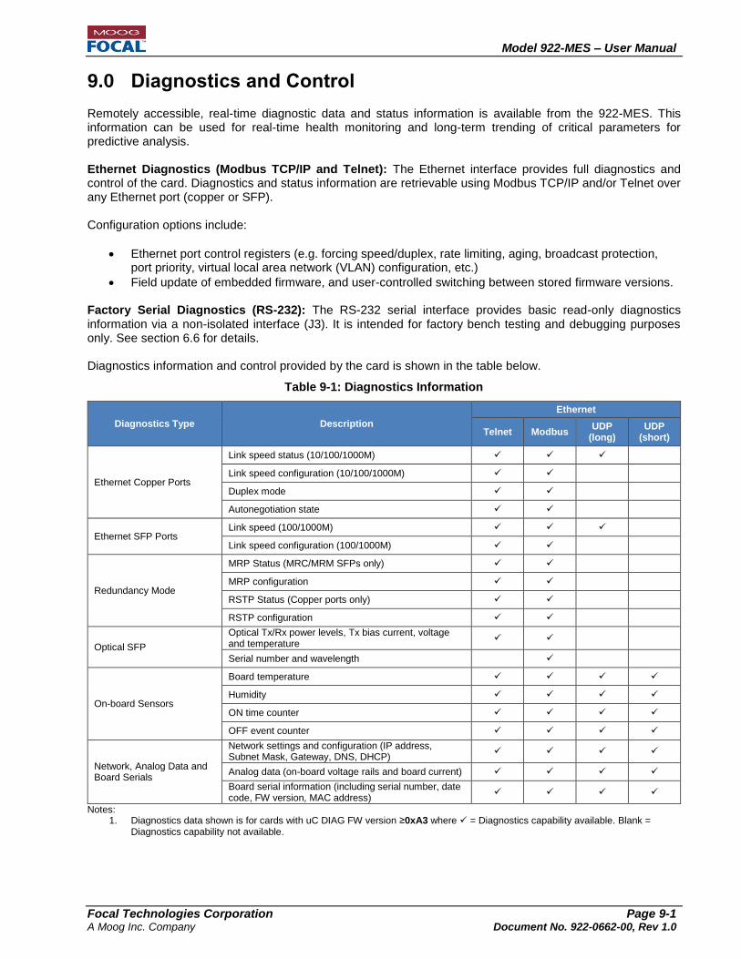
Model 922-MES – User Manual
Focal Technologies Corporation Page 9-1 A Moog Inc. Company Document No. 922-0662-00, Rev 1.0
9.0 Diagnostics and Control
Remotely accessible, real-time diagnostic data and status information is available from the 922-MES. This information can be used for real-time health monitoring and long-term trending of critical parameters for predictive analysis. Ethernet Diagnostics (Modbus TCP/IP and Telnet): The Ethernet interface provides full diagnostics and control of the card. Diagnostics and status information are retrievable using Modbus TCP/IP and/or Telnet over any Ethernet port (copper or SFP). Configuration options include:
Ethernet port control registers (e.g. forcing speed/duplex, rate limiting, aging, broadcast protection, port priority, virtual local area network (VLAN) configuration, etc.)
Field update of embedded firmware, and user-controlled switching between stored firmware versions. Factory Serial Diagnostics (RS-232): The RS-232 serial interface provides basic read-only diagnostics information via a non-isolated interface (J3). It is intended for factory bench testing and debugging purposes only. See section 6.6 for details. Diagnostics information and control provided by the card is shown in the table below.
Table 9-1: Diagnostics Information
Diagnostics Type Description
Ethernet
Telnet Modbus UDP
(long) UDP
(short)
Ethernet Copper Ports
Link speed status (10/100/1000M)
Link speed configuration (10/100/1000M)
Duplex mode
Autonegotiation state
Ethernet SFP Ports Link speed (100/1000M)
Link speed configuration (100/1000M)
Redundancy Mode
MRP Status (MRC/MRM SFPs only)
MRP configuration
RSTP Status (Copper ports only)
RSTP configuration
Optical SFP
Optical Tx/Rx power levels, Tx bias current, voltage and temperature
Serial number and wavelength
On-board Sensors
Board temperature
Humidity
ON time counter
OFF event counter
Network, Analog Data and Board Serials
Network settings and configuration (IP address, Subnet Mask, Gateway, DNS, DHCP)
Analog data (on-board voltage rails and board current)
Board serial information (including serial number, date code, FW version, MAC address)
Notes: 1. Diagnostics data shown is for cards with uC DIAG FW version ≥0xA3 where = Diagnostics capability available. Blank =
Diagnostics capability not available.

Model 922-MES – User Manual
Focal Technologies Corporation Page 9-2 A Moog Inc. Company Document No. 922-0662-00, Rev 1.0
9.1 Modbus TCP/IP The Modbus TCP protocol is used to provide diagnostics and user control messages via a TCP/IP connection to the 922-MES. Local card status and control registers are accessible via Modbus TCP/IP from the topside or other subsea equipment over any Ethernet port. Diagnostic information available is shown in Table 9-1. The Modbus TCP register map is provided in the “MES Diagnostics Protocol Manual” document 922-0673-02.
9.2 Telnet Interface The 922-MES card implements a Telnet server on port 23. The server can be accessed from a PC-based Telnet client such as Microsoft Telnet ClientTM or Tera Term by entering the card’s IP address. Once a connection has been established, the Telnet interface displays a home screen containing a list of the available commands and also detailed help on using each command. Typically the Telnet interface is used for convenient configuration of the card. The commands available in the Telnet interface are shown in the figure below. Detailed help for each command is available from the Telnet
menu by sending the “help” command. A description of all commands is provided in document 922-0673-02.
Figure 9-1: Telnet Interface Commands

Model 922-MES – User Manual
Focal Technologies Corporation Page 9-3 A Moog Inc. Company Document No. 922-0662-00, Rev 1.0
9.3 Graphical User Interface (GUI) Focal has created a sample version of a .NET graphical user interface (GUI) for use on Microsoft Windows with a Modbus TCP backend for integration and bench testing the Model 922 Modbus functionality. Typically users have or develop their own Modbus TCP interfaces for local PLCs and other controllers. A screenshot of the sample GUI is shown in the figure below. More information on the use of this software can be found in document 922-0673-01.
Figure 9-2: Sample .NET GUI for Modbus TCP Access to Model 922-MES