Model 9100 M to color display Field c p - Triton Systems · 2 9100 MonochroMe to color display...
8
Model 9100 MonochroMe to color display Field conversion procedure tdn 07103-00206 Feb 19 2010 COPYRIGHT NOTICE © 2010 Triton. All Rights Reserved. TRITON logo is a registered trademark of Triton Systems of Delaware, LLC 21405 B Street Long Beach, MS 39560 Phone: (800) 259-6672 Fax: (228) 868-9445 corporate headquarters:
Transcript of Model 9100 M to color display Field c p - Triton Systems · 2 9100 MonochroMe to color display...
Model 9100MonochroMe to color display
Field conversion procedure
tdn 07103-00206 Feb 19 2010
COPYRIGHT NOTICE© 2010 Triton. All Rights Reserved. TRITON logo is a registered trademark of Triton Systems of Delaware, LLC
21405 B StreetLong Beach, MS 39560Phone: (800) 259-6672Fax: (228) 868-9445
corporate headquarters:
2
9100 MonochroMe to color display conversion
contents
perForMing the 9100 MonochroMe to color display conversion
introduction
This guide covers the steps for converting the 9100 series terminal from a monochrome to a color display. The following procedures include a list of tools and the hardware required for the conversion.
scope
The following procedures apply to all Triton certified service personnel involved in the process of maintaining or converting Triton ATMs.
overview
The 9100 Monochrome to Color Display Conversion will require the replacement of the display assembly and main board. The kit includes all cabling and associated mounting hardware.
Document Updates
Feb 19 2010 Original
IntroductIon........................................................................................................................................2Scope...............................................................................................................................................................2overvIew.........................................................................................................................................................2requIred partS and toolS.............................................................................................................................3remove and replace maIn Board..................................................................................................................3remove dISplay...............................................................................................................................................5InStall color dISplay.....................................................................................................................................6
3
Field conversion procedure
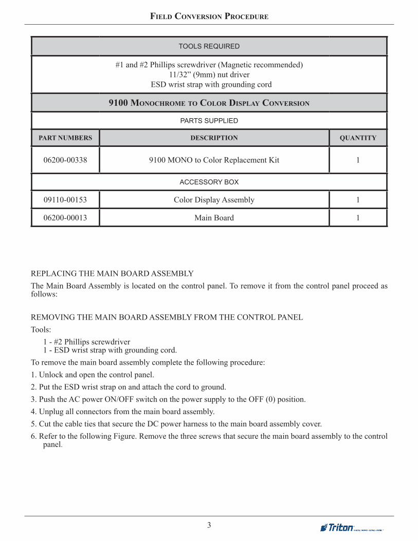
TOOLS REQUIRED
#1 and #2 Phillips screwdriver (Magnetic recommended)11/32” (9mm) nut driver
ESD wrist strap with grounding cord
9100 MonochroMe to color display conversion
PARTS SUPPLIED
PART NUMBERS description quantity
06200-00338 9100 MONO to Color Replacement Kit 1
ACCESSORY BOX
09110-00153 Color Display Assembly 1
06200-00013 Main Board 1
REPLACING THE MAIN BOARD ASSEMBLYThe Main Board Assembly is located on the control panel. To remove it from the control panel proceed as follows:
REMOVING THE MAIN BOARD ASSEMBLY FROM THE CONTROL PANELTools:
1 - #2 Phillips screwdriver1 - ESD wrist strap with grounding cord.
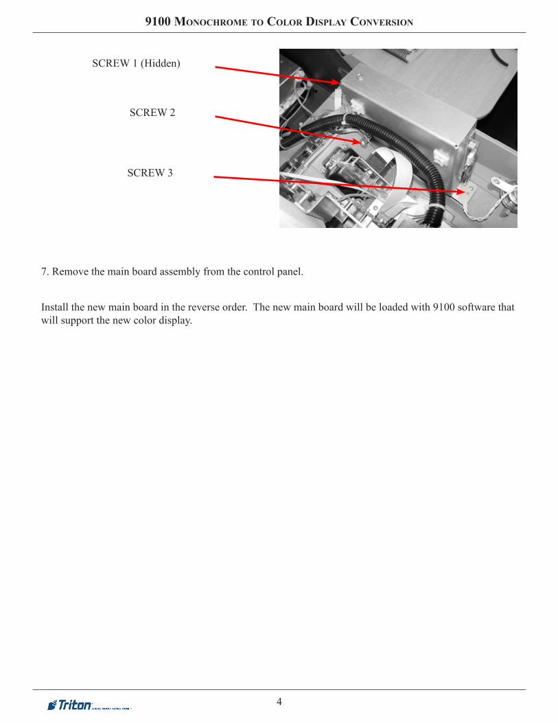
To remove the main board assembly complete the following procedure:1. Unlock and open the control panel.2. Put the ESD wrist strap on and attach the cord to ground.3. Push the AC power ON/OFF switch on the power supply to the OFF (0) position.4. Unplug all connectors from the main board assembly.5. Cut the cable ties that secure the DC power harness to the main board assembly cover.6. Refer to the following Figure. Remove the three screws that secure the main board assembly to the control
panel.
4
9100 MonochroMe to color display conversion
SCREW 1 (Hidden)
SCREW 3
SCREW 2
7. Remove the main board assembly from the control panel.
Install the new main board in the reverse order. The new main board will be loaded with 9100 software that will support the new color display.
5
Field conversion procedure
10. Carefully remove the printer/printer control board and LCD assembly from the control panel. Be care-ful not get fingerprints on the display or damage the display shield.
11. Place the printer/printer control board and display assembly on a clean flat surface.
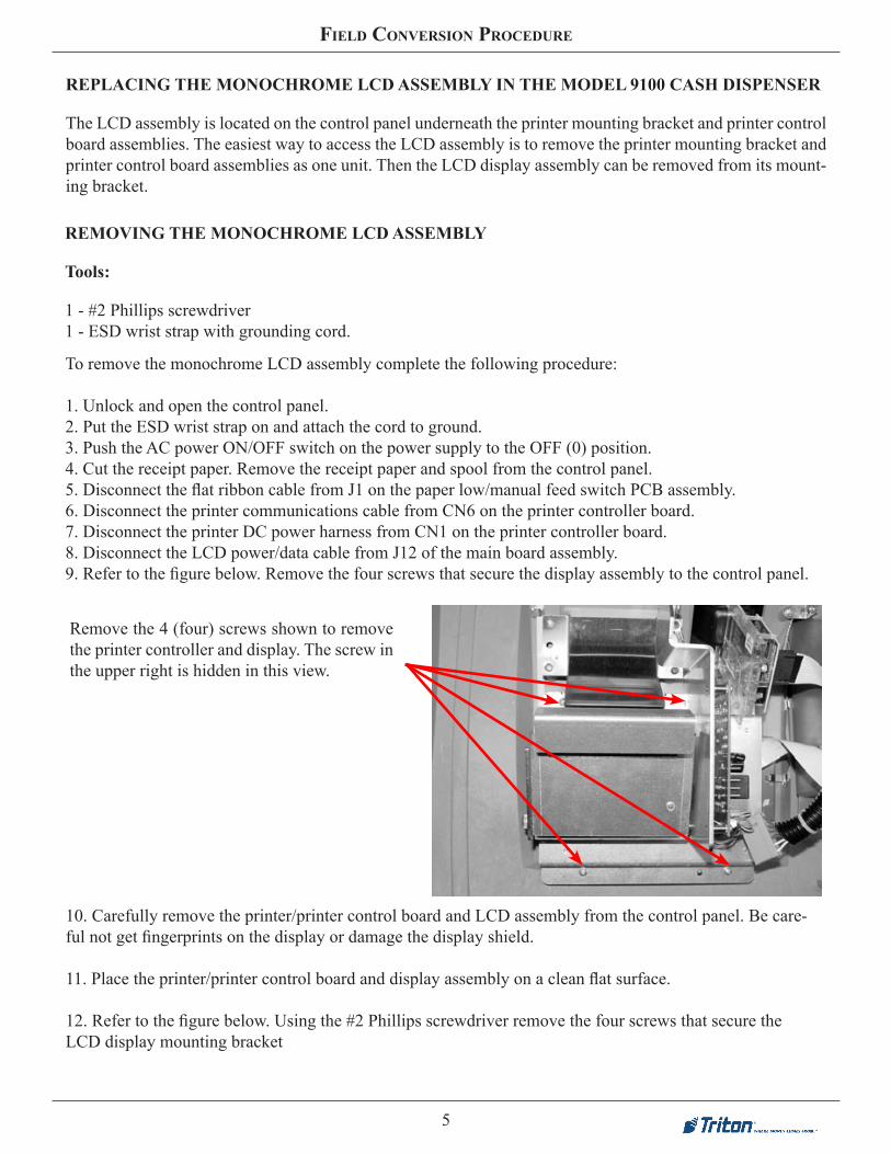
12. Refer to the figure below. Using the #2 Phillips screwdriver remove the four screws that secure the LCD display mounting bracket
Remove the 4 (four) screws shown to remove the printer controller and display. The screw in the upper right is hidden in this view.
REPLACING THE MONOCHROME LCD ASSEMBLY IN THE MODEL 9100 CASH DISPENSER
The LCD assembly is located on the control panel underneath the printer mounting bracket and printer control board assemblies. The easiest way to access the LCD assembly is to remove the printer mounting bracket and printer control board assemblies as one unit. Then the LCD display assembly can be removed from its mount-ing bracket.
REMOVING THE MONOCHROME LCD ASSEMBLY
Tools:
1 - #2 Phillips screwdriver1 - ESD wrist strap with grounding cord.
To remove the monochrome LCD assembly complete the following procedure:
1. Unlock and open the control panel.2. Put the ESD wrist strap on and attach the cord to ground.3. Push the AC power ON/OFF switch on the power supply to the OFF (0) position.4. Cut the receipt paper. Remove the receipt paper and spool from the control panel.5. Disconnect the flat ribbon cable from J1 on the paper low/manual feed switch PCB assembly.6. Disconnect the printer communications cable from CN6 on the printer controller board.7. Disconnect the printer DC power harness from CN1 on the printer controller board.8. Disconnect the LCD power/data cable from J12 of the main board assembly.9. Refer to the figure below. Remove the four screws that secure the display assembly to the control panel.
6
9100 MonochroMe to color display conversion
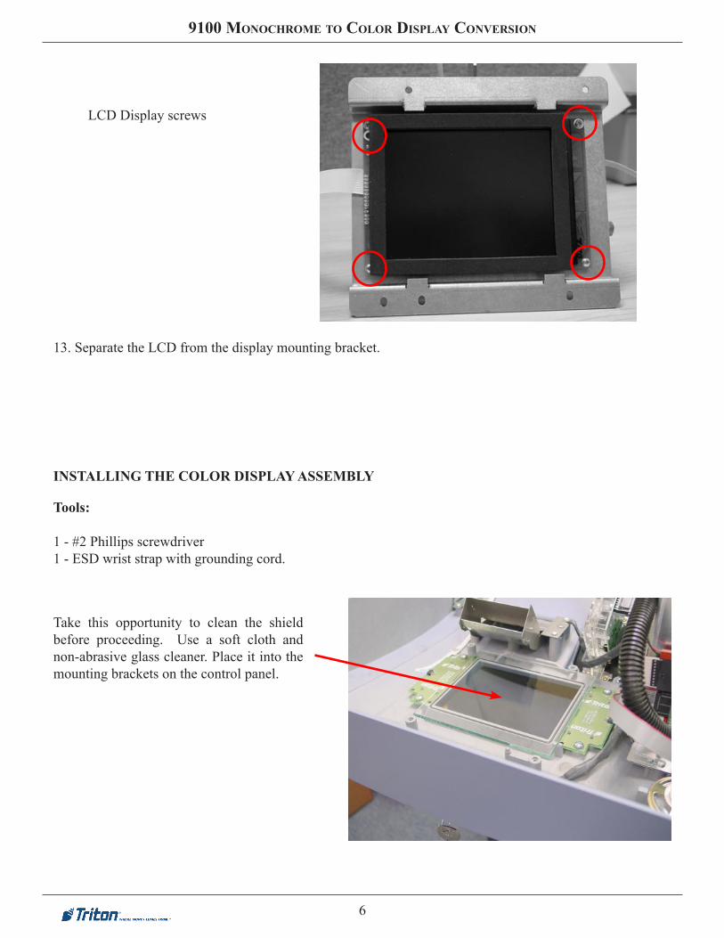
LCD Display screws
13. Separate the LCD from the display mounting bracket.
INSTALLING THE COLOR DISPLAY ASSEMBLY
Tools:
1 - #2 Phillips screwdriver1 - ESD wrist strap with grounding cord.
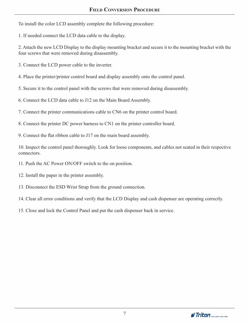
Take this opportunity to clean the shield before proceeding. Use a soft cloth and non-abrasive glass cleaner. Place it into the mounting brackets on the control panel.
7
Field conversion procedure
11. Push the AC Power ON/OFF switch to the on position.
12. Install the paper in the printer assembly.
13. Disconnect the ESD Wrist Strap from the ground connection.
14. Clear all error conditions and verify that the LCD Display and cash dispenser are operating correctly.
15. Close and lock the Control Panel and put the cash dispenser back in service.
To install the color LCD assembly complete the following procedure:
1. If needed connect the LCD data cable to the display.
2. Attach the new LCD Display to the display mounting bracket and secure it to the mounting bracket with the four screws that were removed during disassembly.
3. Connect the LCD power cable to the inverter.
4. Place the printer/printer control board and display assembly onto the control panel.
5. Secure it to the control panel with the screws that were removed during disassembly.
6. Connect the LCD data cable to J12 on the Main Board Assembly.
7. Connect the printer communications cable to CN6 on the printer control board.
8. Connect the printer DC power harness to CN1 on the printer controller board.
9. Connect the flat ribbon cable to J17 on the main board assembly.
10. Inspect the control panel thoroughly. Look for loose components, and cables not seated in their respective connectors.

8
9100 MonochroMe to color display conversion
this page intentionally leFt blank